EP1527856A2 - Längsschneidemaschine mit einer Einrichtung zum automatischen Wechseln von Schneideinrichtungen - Google Patents
Längsschneidemaschine mit einer Einrichtung zum automatischen Wechseln von Schneideinrichtungen Download PDFInfo
- Publication number
- EP1527856A2 EP1527856A2 EP04103427A EP04103427A EP1527856A2 EP 1527856 A2 EP1527856 A2 EP 1527856A2 EP 04103427 A EP04103427 A EP 04103427A EP 04103427 A EP04103427 A EP 04103427A EP 1527856 A2 EP1527856 A2 EP 1527856A2
- Authority
- EP
- European Patent Office
- Prior art keywords
- knife
- blade
- magazine
- cutting machine
- holder
- Prior art date
- Legal status (The legal status is an assumption and is not a legal conclusion. Google has not performed a legal analysis and makes no representation as to the accuracy of the status listed.)
- Granted
Links
- 238000005520 cutting process Methods 0.000 title claims abstract description 57
- 238000000034 method Methods 0.000 description 3
- 230000006978 adaptation Effects 0.000 description 1
- 238000011161 development Methods 0.000 description 1
- 230000018109 developmental process Effects 0.000 description 1
- 238000006073 displacement reaction Methods 0.000 description 1
Images


Classifications
-
- B—PERFORMING OPERATIONS; TRANSPORTING
- B23—MACHINE TOOLS; METAL-WORKING NOT OTHERWISE PROVIDED FOR
- B23D—PLANING; SLOTTING; SHEARING; BROACHING; SAWING; FILING; SCRAPING; LIKE OPERATIONS FOR WORKING METAL BY REMOVING MATERIAL, NOT OTHERWISE PROVIDED FOR
- B23D35/00—Tools for shearing machines or shearing devices; Holders or chucks for shearing tools
- B23D35/008—Means for changing the cutting members
-
- Y—GENERAL TAGGING OF NEW TECHNOLOGICAL DEVELOPMENTS; GENERAL TAGGING OF CROSS-SECTIONAL TECHNOLOGIES SPANNING OVER SEVERAL SECTIONS OF THE IPC; TECHNICAL SUBJECTS COVERED BY FORMER USPC CROSS-REFERENCE ART COLLECTIONS [XRACs] AND DIGESTS
- Y10—TECHNICAL SUBJECTS COVERED BY FORMER USPC
- Y10T—TECHNICAL SUBJECTS COVERED BY FORMER US CLASSIFICATION
- Y10T83/00—Cutting
- Y10T83/929—Tool or tool with support
- Y10T83/9372—Rotatable type
Definitions
- the invention relates to a slitter with a plurality of it salaried cutting devices in the form of a respective knife holder as a carrier a circular knife arranged thereon.
- the problem is that the change the circular knife is time consuming on a single knife holder, because the Removed circular knives on the relevant knife holder by hand and inserted new knife must be mounted.
- the holder of the knife blades on the cutter head of the knife holder for example by means of appropriately trained blade attachments dismantling or the assembly costs are reduced, the use of an operator is required; especially at a small distance from each other on the slitter arranged knife holders can because of the required manual work considerable set-up times for the knife change arise.
- the invention is therefore based on the object, a longitudinal cutting machine of the aforementioned type so that the for a blade change required setup times are shortened.
- the invention provides in its basic idea that a device for automatic change of the cutting device is provided, which is a magazine for storing at least one new cutting device and one automatically working tool assembly for removing the cutting device and the Assembling the removed from the magazine new cutting device comprises.
- the idea of the invention is thus embodied in that on the longitudinal cutting machine a device is provided which, in response to a control command Changing one or more cutting devices automatically performs and for this purpose, the newly mounted cutting device or the cutting devices carries in a magazine and at the same time is able to over a automatically working tool assembly to the respective cutting device disassemble and replace with a new cutter.
- the device detects as a removable part the cutting device only the knife blade held on the knife holder, so that carry in the magazine and only individual knife blades and to be kept in stock for tampering.
- the device including the knife blade connected to the knife blade and the holder of the knife blade the knife holder serving knife attachments as change parts of the respective Detects cutting devices, and again may alternatively be provided the device comprises the complete cutter head supported on the knife holder detected as a carrier of the knife blade as a change part of the cutting device.
- the institution magazines each trained accordingly to receive the removable parts, and it must be the tool assembly for disassembly or assembly of the respective Interchangeable part be set up.
- the device comprises the knife holder held on the slitter detected as a change part of the cutting device, so that the thought of the invention is to change the complete fair holder; this It can even be simpler mechanically than changing a single one Circular knife.
- a suitably trained magazine can quite a Number of complete knife holders are carried. This is not just the Possibility of a knife change, but also a depth adjustment on Knife holder as well as an overhaul of the knife holder given.
- the device from one on each blade holder between one for the change of Circular knife suitable working position and a loading position rotatable salaried support arm and at the outer end of the support arm, the magazine is mounted with the tool assembly for the blade change.
- the magazine needs in the magazine only one removable part in the form a knife blade or a knife blade including knife attachments or a cutter head, because after every blade change and Swiveling the support arm into the mounting position independently of the further cutting work of the slitter for the next replacement process the respective replacement part can be inserted into the magazine.
- the magazine with the tool assembly along an associated traverse is movable, as far as the magazine while in Distance to the knife holder is, can be provided, the tool assembly by means of a piston rod in a suitable for the parts change working position extend.
- the device be interpreted that on several knife holders in a sequence of change is feasible, the magazine according to accommodate multiple change parts must be set up, and must also be the tool assembly not only for the assembly and disassembly of the removable part but also for the removal of the spare parts and the introduction of the used parts in the Be furnished magazine.
- the device on a longitudinal cutting machine movable carriage is supported and on the carriage between a suitable for the change of the cutting device working position and a loading position movable support arm is arranged, at whose End of the magazine is attached to the tool assembly, in particular It can be provided that the support arm pivots on the carriage is arranged. Also in this case are magazine and tool arrangement for set up a multiple part change.
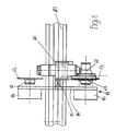
- a Knife holder 11 On the traverse 10 a slitter not shown is a Knife holder 11 arranged movable, which carries a cutter head 12 at which in turn a circular blade 13 is supported.
- a device 19 for a automatic blade change is on the blade holder 11 a to a pivot bearing 15 pivotable support arm 14 arranged at the end of a magazine 16 sits, which with a movable tool assembly 17 for an automatic Knife change is connected.
- the working position is in solid lines of the magazine 16 shown with tool assembly 17, in which means a suitable design of the tool assembly 17, the disassembly of the Circular knife 13 and then a montage of a new, from the magazine 16 removed circular knife can be done.
- dashed lines is the position the support arm 14 shown after pivoting in a loading position, in which now during the cutting operation, the used circular blade to remove from the magazine 16 and replace it with a new circular knife is, which then by pivoting the support arm 14 in the solid Lines shown working position for a new blade change available stands.
- the support arm 14 is inclusive Magazine 16 and tool assembly 17 on one of the traverse 10th the longitudinal cutting machine movably arranged carriage 20 is supported, wherein the carriage 20 successively start a plurality of knife holders 11 and perform the appropriate blade change.
- the support arm be pivoted after a completed blade change so that the each equipped knife holder 11 can be run over and the support arm 14th to gain access to the next knife holder.
- It is in a not shown Way by designing the tool assembly 17 to ensure that each several knives removed from the magazine 16 and several Use parts can be sequentially set in the magazine 16.
- dashed Lines is again shown the placement position in which the Removing the utility knife from the magazine 16 and the setting of new knives can be made in the magazine 16.
- the magazine is 16 arranged on additional trusses 30 by means of a holder 25 and movable, wherein in the illustrated embodiment, the knife holder 11 by means of a holder piece 31 on the traverse 10 of the longitudinal cutting machine is movable. Furthermore, the knife holder 11 is a positioning device 32 for associated with the displacement of the knife holder 11. As shown in the Embodiment, the magazine 16 at a distance from the knife holder eleventh is movable, the tool assembly 17 by means of a piston rod 26 in the Movable working position.
Landscapes
- Engineering & Computer Science (AREA)
- Mechanical Engineering (AREA)
- Details Of Cutting Devices (AREA)
- Accessories And Tools For Shearing Machines (AREA)
Abstract
Description
- Fig. 1
- einen an einer Längsschneidemaschine gehalterten Messerhalter mit Kreismesser und zugeordneter Messerwechseleinrichtung in einer schematischen Seitenansicht,
- Fig. 2
- den Gegenstand der Figur 1 in einer anderen Ausführungsform,
- Fig. 3
- den Gegenstand der Figur 1 in einer weiteren Ausführungsform.
- 10
- Traverse
- 11
- Messerhalter
- 12
- Messerkopf
- 13
- Kreismesser
- 14
- Tragarm
- 15
- Drehlager
- 16
- Magazin
- 17
- Werkzeuganordnung
- 19
- Einrichtung
- 20
- Schlitten
- 25
- Halter
- 26
- Kolbenstange
- 30
- Traverse
- 31
- Halterstück
- 32
- Positioniereinrichtung
Claims (10)
- Längsschneidemaschine mit einer Mehrzahl von daran gehalterten Schneideinrichtungen in Form jeweils eines Messerhalters (11) als Träger eines daran angeordneten Kreismessers (13),
dadurch gekennzeichnet, dass eine Einrichtung (19) zum automatischen Wechsel der Schneideinrichtung (13) vorgesehen ist, die ein Magazin (16) zur Bevorratung wenigstens einer neuen Schneideinrichtung und eine automatisch arbeitende Werkzeuganordnung (17) zum Ausbau der Schneideinrichtung und zur Montage der aus dem Magazin entnommenen neuen Schneideinrichtung (13) umfasst. - Längsschneidemaschine nach Anspruch 1,
dadurch gekennzeichnet, dass die Einrichtung (19) das an dem Messerhalter (11) gehalterte Messerblatt als Wechselteil der Schneideinrichtung erfasst. - Längsschneidemaschine nach Anspruch 1,
dadurch gekennzeichnet, dass die Einrichtung (19) das Messerblatt einschließlich mit dem Messerblatt verbundener und der Halterung des Messerblattes an dem Messerhalter (11) dienender Messeranbauteile als Wechselteil der Schneideinrichtung erfasst. - Längsschneidemaschine nach Anspruch 1,
dadurch gekennzeichnet, dass die Einrichtung den an dem Messerhalter (11) gehalterten vollständigen Messerkopf (12) als Träger des Messerblattes als Wechselteil der Schneideinrichtung erfasst. - Längsschneidemaschine nach Anspruch 1,
dadurch gekennzeichnet, dass die Einrichtung den an der Längsschneidemaschine gehalterten Messerhalter (11) als Wechselteil der Schneideinrichtung erfasst. - Längsschneidemaschine nach einem der Ansprüche 1 bis 4,
dadurch gekennzeichnet, dass die Einrichtung (19) aus einem an jedem Messerhalter (11) zwischen einer für den Wechsel des Kreismessers (13) geeigneten Arbeitsposition und einer Bestückungsposition drehbar gehalterten Tragarm (14) besteht und an dem äußeren Ende des Tragarms (14) das Magazin (16) mit der Werkzeuganordnung (17) für den Messerwechsel angebracht ist. - Längsschneidemaschine nach einem der Ansprüche 1 bis 5,
dadurch gekennzeichnet, dass das Magazin (16) mit der Werkzeuganordnung (17) längs einer zugeordneten Traverse (30) verfahrbar ist. - Längsschneidemaschine nach Anspruch 6,
dadurch gekennzeichnet, dass die Werkzeuganordnung (17) mittels einer Kolbenstange (26) aus dem mit Abstand zum Messerhalter (11) stehenden Magazin (16) in eine für den Wechsel der Schneideinrichtung geeignete Arbeitsposition ausfahrbar ist. - Längsschneidemaschine nach einem der Ansprüche 1 bis 5,
dadurch gekennzeichnet, dass die Einrichtung (19) an einem längs der Längsschneidemaschine verfahrbaren Schlitten (20) gehaltert ist und an dem Schlitten (20) ein zwischen einer für den Wechsel der Schneideinrichtung geeigneten Arbeitsposition und einer Bestückungsposition beweglicher Tragarm (14) angeordnet ist, an dessen Ende das Magazin (16) mit der Werkzeuganordnung (17) für den Wechsel der Schneideinrichtung angebracht ist. - Längsschneidemaschine nach Anspruch 9,
dadurch gekennzeichnet, dass der Tragarm (14) an dem Schlitten (20) schwenkbar angeordnet ist.
Applications Claiming Priority (2)
| Application Number | Priority Date | Filing Date | Title |
|---|---|---|---|
| DE20311973U DE20311973U1 (de) | 2003-07-31 | 2003-07-31 | Für einen automatischen Messerwechsel eingerichtete Längsschneidemaschine |
| DE20311973U | 2003-07-31 |
Publications (3)
| Publication Number | Publication Date |
|---|---|
| EP1527856A2 true EP1527856A2 (de) | 2005-05-04 |
| EP1527856A3 EP1527856A3 (de) | 2005-07-20 |
| EP1527856B1 EP1527856B1 (de) | 2006-12-20 |
Family
ID=28799366
Family Applications (1)
| Application Number | Title | Priority Date | Filing Date |
|---|---|---|---|
| EP20040103427 Expired - Lifetime EP1527856B1 (de) | 2003-07-31 | 2004-07-19 | Längsschneidemaschine mit einer Einrichtung zum automatischen Wechseln von Schneideinrichtungen |
Country Status (3)
| Country | Link |
|---|---|
| US (1) | US20060021486A1 (de) |
| EP (1) | EP1527856B1 (de) |
| DE (2) | DE20311973U1 (de) |
Families Citing this family (2)
| Publication number | Priority date | Publication date | Assignee | Title |
|---|---|---|---|---|
| DE102011109067A1 (de) * | 2011-08-01 | 2013-02-07 | Weber Maschinenbau Gmbh Breidenbach | Vorrichtung und Verfahren zum Aufschneiden von Lebensmittelprodukten |
| JP6676937B2 (ja) * | 2015-11-19 | 2020-04-08 | 株式会社リコー | アンテナ装置、通信装置、及びアンテナ装置の製造方法 |
Family Cites Families (15)
| Publication number | Priority date | Publication date | Assignee | Title |
|---|---|---|---|---|
| US3990140A (en) * | 1974-11-20 | 1976-11-09 | Houdaille Industries, Inc. | Vertical tool changer to adapter holding mechanism |
| DE8526544U1 (de) * | 1985-09-17 | 1987-04-23 | Chiron-Werke Gmbh, 7200 Tuttlingen | Werkzeugmaschine |
| IT208084Z2 (it) * | 1985-11-12 | 1988-03-31 | Cavagna Elio Srl | Portalama con lama circolare rapidamente intercambiabile. |
| EP0267156B1 (de) * | 1986-11-04 | 1994-12-07 | Fritz Krüsi Maschinenbau | Vorrichtung zum Bearbeiten eines Werkstückes aus Holz, insbesondere von Holzbalken |
| DE9303048U1 (de) * | 1993-03-03 | 1993-05-13 | Festo KG, 7300 Esslingen | Arbeitszylinder-Anordnung |
| DE4421385C2 (de) * | 1994-06-18 | 1997-01-23 | Chiron Werke Gmbh | Werkzeugmaschine mit einer Werkzeugwechselvorrichtung |
| DE19516347C2 (de) * | 1995-05-04 | 1997-07-31 | Kg Schneider Senator Verkaufs | Verfahren zum Wechseln des Messers |
| EP0761384B1 (de) * | 1995-09-02 | 2000-04-12 | Chiron-Werke GmbH & Co. KG | Werkzeugmaschine |
| IT1279651B1 (it) * | 1995-10-11 | 1997-12-16 | Selco Srl | Macchina sezionatrice di pezzi. |
| US6350222B2 (en) * | 1999-07-28 | 2002-02-26 | Thermwood Corporation | Machine tool with improved tool changer means |
| US6416450B2 (en) * | 1999-07-28 | 2002-07-09 | Thermwood Corporation | Machine tool with improved tool changer means |
| JP2002036052A (ja) * | 2000-07-25 | 2002-02-05 | Sankyo Mfg Co Ltd | 自動工具交換装置 |
| US6494821B1 (en) * | 2000-08-31 | 2002-12-17 | Hurco Companies, Inc. | Movable arm activated tool changer for machine tool system |
| DE20120017U1 (de) * | 2001-12-11 | 2002-02-28 | Wilhelm Bilstein KG Spezialfabrik für Maschinenmesser und Kompressorventile, 51491 Overath | Einrichtung zum Längsteilen von Materialbahnen mit einer zentralen Feststelleinrichtung für verschieb- und festlegbare Schneideinrichtungen |
| ATE448047T1 (de) * | 2002-05-22 | 2009-11-15 | Hermle Berthold Maschf Ag | Werkzeughandhabungsvorrichtung für eine werkzeugmaschine |
-
2003
- 2003-07-31 DE DE20311973U patent/DE20311973U1/de not_active Expired - Lifetime
-
2004
- 2004-07-19 DE DE200450002363 patent/DE502004002363D1/de not_active Expired - Fee Related
- 2004-07-19 EP EP20040103427 patent/EP1527856B1/de not_active Expired - Lifetime
- 2004-08-02 US US10/903,250 patent/US20060021486A1/en not_active Abandoned
Also Published As
| Publication number | Publication date |
|---|---|
| DE502004002363D1 (de) | 2007-02-01 |
| EP1527856B1 (de) | 2006-12-20 |
| DE20311973U1 (de) | 2003-10-02 |
| US20060021486A1 (en) | 2006-02-02 |
| EP1527856A3 (de) | 2005-07-20 |
Similar Documents
| Publication | Publication Date | Title |
|---|---|---|
| DE2540979C2 (de) | Automatische Werkzeugwechselvorrichtung für eine Vertikal- oder Karusselldrehmaschine | |
| EP2415538B1 (de) | Vorrichtung zur Bearbeitung von Werkstücken | |
| DE102009024075A1 (de) | Biegevorrichtung für stabförmige Werkstücke | |
| EP1964653A1 (de) | Plattenaufteilanlage zum Aufteilen von plattenförmigen Werkstücken, sowie Verfahren zu deren Betrieb | |
| DE3440224C2 (de) | Werkzeugwechselvorrichtung an einer Stanz- oder Nibbelmaschine | |
| EP2915622A1 (de) | Bearbeitungsmaschine, insbesondere schleifmaschine, mit einem drehbaren werkzeugmagazin | |
| DE19843889B4 (de) | Stanzwerkzeug-Speicher-und Wechselsystem | |
| DE102004034911A1 (de) | Werkzeugmaschine und damit ausgestattete Bearbeitungslinie | |
| DE102011052538A1 (de) | Vorrichtung zum Schärfen von Messern eines Messerrings für einenMesserringzerspaner | |
| DE102008026330A1 (de) | Plattenaufteilanlage | |
| DE202009018934U1 (de) | Werkzeugmaschine | |
| DE3230051C2 (de) | ||
| EP3294498B1 (de) | Verfahren und bearbeitungsvorrichtung zum spannen und zum bearbeiten eines schaltschrankbauteils | |
| DE10335085B4 (de) | Setzwerkzeug mit auswechselbaren Baugruppen | |
| EP2092994B1 (de) | Werkzeugmaschine zum Schneiden und/oder Umformen von plattenartigen Werkstücken | |
| DE19858791B4 (de) | Plattenbearbeitungsmaschine | |
| DE19909402C2 (de) | Verfahren und Vorrichtung zum Beschneiden und Bohren von papierwerkstoffartigen, stapelbaren Materialien | |
| EP1527856B1 (de) | Längsschneidemaschine mit einer Einrichtung zum automatischen Wechseln von Schneideinrichtungen | |
| EP0074041B1 (de) | Schneidpresse zur Bearbeitung von tafelförmigen Werkstücken | |
| DE19920101A1 (de) | Sägeblattschleifmaschine | |
| AT518255B1 (de) | Werkzeugwechselvorrichtung für eine Abkantpresse und Verfahren zum Durchführen eines Werkzeugwechsels | |
| DE3005089C2 (de) | Vorrichtung zur auswechselbaren Halterung einer Matrize eines Werkzeugs in einer Metallbearbeitungsmaschine und Werkzeug zur Auswechslung der Matrize | |
| DE102014100476A1 (de) | Roboter-Stanzzelle | |
| DE10117951B4 (de) | Verfahren zum Wechseln eines rotationssymmetrischen Schneidwerkzeuges sowie Einrichtung zur Durchführung des Verfahrens | |
| DE102007006593A1 (de) | Kabelbearbeitungseinrichtung mit mehreren Bearbeitungsstationen zur Konfektionierung eines Kabels |
Legal Events
| Date | Code | Title | Description |
|---|---|---|---|
| PUAI | Public reference made under article 153(3) epc to a published international application that has entered the european phase |
Free format text: ORIGINAL CODE: 0009012 |
|
| AK | Designated contracting states |
Kind code of ref document: A2 Designated state(s): AT BE BG CH CY CZ DE DK EE ES FI FR GB GR HU IE IT LI LU MC NL PL PT RO SE SI SK TR |
|
| AX | Request for extension of the european patent |
Extension state: AL HR LT LV MK |
|
| PUAL | Search report despatched |
Free format text: ORIGINAL CODE: 0009013 |
|
| AK | Designated contracting states |
Kind code of ref document: A3 Designated state(s): AT BE BG CH CY CZ DE DK EE ES FI FR GB GR HU IE IT LI LU MC NL PL PT RO SE SI SK TR |
|
| AX | Request for extension of the european patent |
Extension state: AL HR LT LV MK |
|
| 17P | Request for examination filed |
Effective date: 20060120 |
|
| AKX | Designation fees paid |
Designated state(s): DE FI SE |
|
| GRAP | Despatch of communication of intention to grant a patent |
Free format text: ORIGINAL CODE: EPIDOSNIGR1 |
|
| RIN1 | Information on inventor provided before grant (corrected) |
Inventor name: SUPE-DIENES, RUDOLF |
|
| RAP1 | Party data changed (applicant data changed or rights of an application transferred) |
Owner name: VOITH PATENT GMBH |
|
| GRAS | Grant fee paid |
Free format text: ORIGINAL CODE: EPIDOSNIGR3 |
|
| GRAA | (expected) grant |
Free format text: ORIGINAL CODE: 0009210 |
|
| AK | Designated contracting states |
Kind code of ref document: B1 Designated state(s): DE FI SE |
|
| REF | Corresponds to: |
Ref document number: 502004002363 Country of ref document: DE Date of ref document: 20070201 Kind code of ref document: P |
|
| REG | Reference to a national code |
Ref country code: SE Ref legal event code: TRGR |
|
| PLBE | No opposition filed within time limit |
Free format text: ORIGINAL CODE: 0009261 |
|
| STAA | Information on the status of an ep patent application or granted ep patent |
Free format text: STATUS: NO OPPOSITION FILED WITHIN TIME LIMIT |
|
| 26N | No opposition filed |
Effective date: 20070921 |
|
| PGFP | Annual fee paid to national office [announced via postgrant information from national office to epo] |
Ref country code: DE Payment date: 20080722 Year of fee payment: 5 |
|
| PGFP | Annual fee paid to national office [announced via postgrant information from national office to epo] |
Ref country code: FI Payment date: 20080715 Year of fee payment: 5 |
|
| PGFP | Annual fee paid to national office [announced via postgrant information from national office to epo] |
Ref country code: SE Payment date: 20080714 Year of fee payment: 5 |
|
| EUG | Se: european patent has lapsed | ||
| PG25 | Lapsed in a contracting state [announced via postgrant information from national office to epo] |
Ref country code: FI Free format text: LAPSE BECAUSE OF NON-PAYMENT OF DUE FEES Effective date: 20090719 |
|
| PG25 | Lapsed in a contracting state [announced via postgrant information from national office to epo] |
Ref country code: DE Free format text: LAPSE BECAUSE OF NON-PAYMENT OF DUE FEES Effective date: 20100202 |
|
| PG25 | Lapsed in a contracting state [announced via postgrant information from national office to epo] |
Ref country code: SE Free format text: LAPSE BECAUSE OF NON-PAYMENT OF DUE FEES Effective date: 20090720 |