EP1527764A2 - Steuerung und Anschlusssystem für eine Badeeinheit - Google Patents
Steuerung und Anschlusssystem für eine Badeeinheit Download PDFInfo
- Publication number
- EP1527764A2 EP1527764A2 EP04292314A EP04292314A EP1527764A2 EP 1527764 A2 EP1527764 A2 EP 1527764A2 EP 04292314 A EP04292314 A EP 04292314A EP 04292314 A EP04292314 A EP 04292314A EP 1527764 A2 EP1527764 A2 EP 1527764A2
- Authority
- EP
- European Patent Office
- Prior art keywords
- contact elements
- bathing unit
- controller
- connectors
- connector
- Prior art date
- Legal status (The legal status is an assumption and is not a legal conclusion. Google has not performed a legal analysis and makes no representation as to the accuracy of the status listed.)
- Withdrawn
Links
- 238000003287 bathing Methods 0.000 title claims abstract description 111
- 230000000295 complement effect Effects 0.000 claims abstract description 112
- 238000010438 heat treatment Methods 0.000 claims description 15
- XLYOFNOQVPJJNP-UHFFFAOYSA-N water Substances O XLYOFNOQVPJJNP-UHFFFAOYSA-N 0.000 description 19
- 239000004020 conductor Substances 0.000 description 15
- 238000004519 manufacturing process Methods 0.000 description 10
- 230000008901 benefit Effects 0.000 description 3
- 230000007935 neutral effect Effects 0.000 description 3
- 230000009467 reduction Effects 0.000 description 3
- CBENFWSGALASAD-UHFFFAOYSA-N Ozone Chemical compound [O-][O+]=O CBENFWSGALASAD-UHFFFAOYSA-N 0.000 description 2
- 230000007812 deficiency Effects 0.000 description 2
- 238000010586 diagram Methods 0.000 description 2
- 238000009826 distribution Methods 0.000 description 2
- 230000003993 interaction Effects 0.000 description 2
- 238000000034 method Methods 0.000 description 2
- 238000012986 modification Methods 0.000 description 2
- 230000004048 modification Effects 0.000 description 2
- 230000009182 swimming Effects 0.000 description 2
- 230000001225 therapeutic effect Effects 0.000 description 2
- 230000003213 activating effect Effects 0.000 description 1
- 239000000919 ceramic Substances 0.000 description 1
- 239000002131 composite material Substances 0.000 description 1
- 239000003989 dielectric material Substances 0.000 description 1
- 239000007788 liquid Substances 0.000 description 1
- 239000000463 material Substances 0.000 description 1
- 239000012811 non-conductive material Substances 0.000 description 1
- 230000008439 repair process Effects 0.000 description 1
- 230000004044 response Effects 0.000 description 1
- 229920002379 silicone rubber Polymers 0.000 description 1
- 239000004945 silicone rubber Substances 0.000 description 1
Images






Classifications
-
- H—ELECTRICITY
- H01—ELECTRIC ELEMENTS
- H01R—ELECTRICALLY-CONDUCTIVE CONNECTIONS; STRUCTURAL ASSOCIATIONS OF A PLURALITY OF MUTUALLY-INSULATED ELECTRICAL CONNECTING ELEMENTS; COUPLING DEVICES; CURRENT COLLECTORS
- H01R27/00—Coupling parts adapted for co-operation with two or more dissimilar counterparts
- H01R27/02—Coupling parts adapted for co-operation with two or more dissimilar counterparts for simultaneous co-operation with two or more dissimilar counterparts
-
- H—ELECTRICITY
- H01—ELECTRIC ELEMENTS
- H01R—ELECTRICALLY-CONDUCTIVE CONNECTIONS; STRUCTURAL ASSOCIATIONS OF A PLURALITY OF MUTUALLY-INSULATED ELECTRICAL CONNECTING ELEMENTS; COUPLING DEVICES; CURRENT COLLECTORS
- H01R13/00—Details of coupling devices of the kinds covered by groups H01R12/70 or H01R24/00 - H01R33/00
- H01R13/64—Means for preventing incorrect coupling
-
- A—HUMAN NECESSITIES
- A61—MEDICAL OR VETERINARY SCIENCE; HYGIENE
- A61H—PHYSICAL THERAPY APPARATUS, e.g. DEVICES FOR LOCATING OR STIMULATING REFLEX POINTS IN THE BODY; ARTIFICIAL RESPIRATION; MASSAGE; BATHING DEVICES FOR SPECIAL THERAPEUTIC OR HYGIENIC PURPOSES OR SPECIFIC PARTS OF THE BODY
- A61H33/00—Bathing devices for special therapeutic or hygienic purposes
- A61H33/005—Electrical circuits therefor
-
- H—ELECTRICITY
- H01—ELECTRIC ELEMENTS
- H01R—ELECTRICALLY-CONDUCTIVE CONNECTIONS; STRUCTURAL ASSOCIATIONS OF A PLURALITY OF MUTUALLY-INSULATED ELECTRICAL CONNECTING ELEMENTS; COUPLING DEVICES; CURRENT COLLECTORS
- H01R13/00—Details of coupling devices of the kinds covered by groups H01R12/70 or H01R24/00 - H01R33/00
- H01R13/64—Means for preventing incorrect coupling
- H01R13/645—Means for preventing incorrect coupling by exchangeable elements on case or base
- H01R13/6456—Means for preventing incorrect coupling by exchangeable elements on case or base comprising keying elements at different positions along the periphery of the connector
-
- H—ELECTRICITY
- H01—ELECTRIC ELEMENTS
- H01R—ELECTRICALLY-CONDUCTIVE CONNECTIONS; STRUCTURAL ASSOCIATIONS OF A PLURALITY OF MUTUALLY-INSULATED ELECTRICAL CONNECTING ELEMENTS; COUPLING DEVICES; CURRENT COLLECTORS
- H01R2201/00—Connectors or connections adapted for particular applications
- H01R2201/12—Connectors or connections adapted for particular applications for medicine and surgery
Definitions
- the present invention relates to controllers suitable for use in bathing units and, more particularly, to controllers having a plurality of connectors for connection to bathing unit components.
- a bathing unit such as a spa, typically includes various components such as a water holding receptacle, pumps to circulate water in a piping system, a heating module to heat the water, a filter system, an air blower, an ozone generator, a lighting system, and a control system for activating and managing the various parameters of the bathing unit components.
- a heating module to heat the water
- a filter system to heat the water
- an air blower to heat the water
- an ozone generator to heat the water
- lighting system a lighting system
- Other types of bathing units having similar components include, for instance, whirlpools, hot tubs, bathtubs, therapeutic baths, and swimming pools.
- the control system of a bathing unit includes a controller to which are connected the various bathing unit components.
- the controller is adapted to control the power supplied to each one of the connected components.
- the controller receives input signals from various input devices, such as for example a plurality of sensors that monitor the various components of the bathing unit and from a control panel allowing a user to control various operational settings of these components.
- the controller activates, or deactivates, the various bathing unit components by supplying power, or ceasing to supply power, to the components.
- different components in a given bathing unit have different operating power requirements. For instance, some of the bathing unit components may require to be powered by way of a 120 volts (V) AC voltage source, while other bathing unit components may require to be powered via a 240 volts (V) AC voltage source.
- different bathing unit components may be designed to operate with different maximum current draws.
- the current draw to operate the various bathing unit components may range, for example, from 0.1 amps (A) for an ozone generator to 20 amps (A) for a large pump.
- the current draw to operate two bathing components of a same type, such as two pumps or two heating modules may also be different for the two components. For instance, one pump may require a current draw of 12 amps (A) to operate, while another pump may require a current draw of 20 amps (A) to operate.
- controllers typically include a plurality of connectors, each connector being adapted to supply power to that particular component in accordance with its power requirements.
- each connector usually includes a set of electrical contact elements, at which a certain voltage or current output will be available.
- a bathing unit includes one component having operating power requirements of 120 volts (V) and 12 amps (A) and another component having operating power requirements of 240 volts (V) and 20 amps (A)
- the controller will thus be configured to include one connector having contact elements at which an output of 120 volts (V) and 12 amps (A) will be available and another connector having contact elements at which an output of 240 volts (V) and 20 amps (A) will be available.
- a deficiency of such a controller configuration is that a bathing unit installer or service person runs the risk of connecting a given bathing unit component to a wrong connector, i.e. in a connector not intended to be connected to that given component.
- a bathing unit installer or service person runs the risk of connecting a given bathing unit component to a wrong connector, i.e. in a connector not intended to be connected to that given component.
- the component with operating power requirements of 120 volts (V) and 12 amps (A) runs the risk of being connected to the controller connector at which an output of 240 volts (V) and 20 amps (A) will be available.
- a proposed solution for avoiding such erroneous connections from being made is to design the controller such that the contact elements of each one of its connectors are arranged in a distinct configuration. This can be achieved, for example, by varying the relative distances separating the contact elements on each connector or, alternatively, by arranging the contact elements of each connector in altogether different patterns.
- Each bathing unit component includes a connector having complementary contact elements arranged in the same distinct configuration as that of the contact elements of the controller connector to which it is intended to be connected. In that way, a controller connector having contact elements arranged in a specific configuration can only be connected to a bathing unit component connector having complementary contact elements arranged in the same specific configuration.
- controllers and bathing unit components of the type described above are deficiency of controllers and bathing unit components of the type described above. From the perspective of a controller manufacturer, this translates into non-optimal production costs or, at the very least, prevents significant economies of scale from being realized. Furthermore, sufficient amounts of inventory of each different type of connectors must be kept in stock such as to allow for the assembly and/or repair of the controllers which adds to the controller manufacturer's costs.
- the invention provides a controller suitable for use in controlling components in a bathing unit.
- the controller comprises a plurality of connectors adapted for providing electrical power to respective bathing unit components.
- Each connector includes a set of contact elements arranged in a common configuration.
- a first subset of the set of contact elements is adapted for generating a power signal characterized by a first current-voltage combination and a second subset of the set of contact elements is adapted for generating a power signal characterized by second current-voltage combination.
- the controller further includes a plurality of key members connected to respective connectors in the plurality connectors so as to allow bathing unit components having complementary key members to be connected to connectors having key members matching the complementary key members.
- the key members may releasably engage the connectors or may be permanently attached thereto.
- the first subset of the set of contact elements is adapted for establishing electrical connections with complementary contact elements associated to a first bathing unit component such as to release a signal characterized by the first current-voltage combination.
- the second subset of the set of contact elements is adapted for establishing electrical connections with complementary contact elements associated to a second bathing unit component such as to release a signal characterized by the second current-voltage combination.
- each of the connectors is adapted to acquire an actuated state and a non-actuated state.
- a connector When in the actuated state, a connector is adapted for providing electrical power to a bathing unit component, and, when in the non-actuated state, a connector is prevented from providing electrical power to a bathing unit component.
- the controller includes a control circuit adapted for controlling a supply of power to the plurality of connectors.
- the control circuit is adapted for receiving control signals associated to components in the bathing unit and for causing selected ones of the plurality of connectors to acquire either one of the actuated state and the non-actuated state on the basis of the control signals.
- the invention provides a connector suitable for providing electrical power to a bathing unit component.
- the connector includes a set of contact elements.
- a first subset of the set of contact elements is adapted for generating a power signal characterized by a first current-voltage combination and a second subset of said set of contact elements is adapted for generating a power signal characterized by second current-voltage combination.
- the set of contact elements includes a plurality of subsets of contact elements associated to respective current-voltage combinations.
- the invention provides a controller suitable for use in controlling components in a bathing unit.
- the controller comprises a plurality of connectors for supplying electrical power to a set of bathing unit components.
- the controller also comprises a plurality of key members connected to respective connectors in the plurality connectors so as to allow bathing unit components having complementary key members to be connected to connectors having key members matching the complementary key members.
- the key members may releasably engage the connectors or may be permanently attached thereto.
- the plurality of key members defines a bathing unit component connection pattern when connected to the plurality of connectors.
- the controller comprises a control circuit adapted for controlling a supply of power to the plurality of connectors in accordance with the bathing unit component connection pattern.
- the invention provides a keying system suitable for use in a bathing unit controller.
- the bathing unit controller includes a connector adapted for providing electrical power to a bathing unit component, where the bathing unit component includes an electrical plug.
- the keying system comprises a key member adapted for engaging the connector and a complementary key member adapted for engaging the electrical plug of the bathing unit, so as to enable the electrical plug and the connector to establish an electrical connection when the key member and the complementary key member match.
- the key member is adapted for releasably engaging the connector or, alternatively, for being permanently attached thereto.
- the complementary key member is adapted for releasably engaging the electrical plug or, alternatively, for being permanently attached thereto.
- the invention provides a bathing unit component suitable for use in a bathing unit having a controller.
- the controller comprises a plurality of connectors for supplying electrical power to a set of bathing unit components.
- the bathing unit component comprises a plug member having a complementary key member connected to the plug so as to allow the bathing unit component to be connected to a connector on the controller having a matching key.
- the invention provides in combination a controller and a plurality of bathing unit components.
- the controller is suitable for use in controlling the bathing unit components and comprises a plurality of connectors.
- Each connector includes a set of contact elements arranged in a common configuration.
- a first subset of the set of contact elements is adapted for generating a power signal characterized by a first current-voltage combination and a second subset of the set of contact elements is adapted for generating a power signal characterized by second current-voltage combination.
- Each of the plurality of bathing unit components is adapted to engage a respective one of the plurality of connectors.
- the combination further includes a plurality of key members adapted for engaging the plurality connectors and a plurality of complementary key members adapted for engaging respective plurality of bathing unit components.
- the plurality of complementary key members allows the bathing unit components to be connected to connectors having a matching key.
- the invention provides a controller suitable for use in controlling components in a bathing unit.
- the controller includes a plurality of connector means for supplying electrical power to a set of bathing unit components and a plurality of key means adapted connected to respective connector means in the plurality of connector means.
- the plurality of key means allowing allow bathing unit components having complementary key members to be connected to connector means having key means matching the complementary key members.
- spa system refers to spas, whirlpools, hot tubs, bathtubs, therapeutic baths, swimming pools and any other type of bathing unit that can be equipped with a control system for controlling various operational settings.
- FIG. 1 illustrates a block diagram of a spa system 10 in accordance with a specific example of implementation.
- the spa system 10 includes a spa receptacle 18 for holding water, a plurality of jets 20, a set of drains 22 and a control system.
- the control system includes a control panel 32, a controller 30, and a plurality of sensors 70 that monitor the various components of the spa.
- the sensors 70 may include temperature and liquid level sensors to respectively monitor the water temperature and water level at various locations in the spa system 10.
- the spa system 10 further includes a plurality of spa components in the form of a heating module 60, two water pumps 11& 12, a filter 26 and an air blower 24. It should be understood that the spa system 10 could include more or less spa components without departing from the spirit of the invention. For example, although not shown in Figure 1, the spa system 10 could include a lighting system for lighting up the water in the receptacle 18.
- the air blower 24 is operative for delivering air bubbles to the spa receptacle 18.
- the control system is operative for controlling the various components of the spa system 10.
- the control panel 32 of the control system is typically in the form of a user interface that allows a user to enter commands for controlling the various operational settings of the spa.
- operational settings of the spa include temperature control settings, jet control settings, and lighting settings.
- the operational settings of the spa may also include audio settings and video settings, amongst others. Consequently, the expression "operational settings", for the purpose of the present invention, is intended to cover operational settings for any suitable equipment that can be used by a spa bather.
- the control system receives electrical power from an electric power source 29 that is connected to the controller 30.
- the controller 30 is then able to control the distribution of power supplied to the various spa components on the basis of control signals received from the various sensors 70 and the control panel 32 in order to cause the desired operational settings to be implemented.
- the power source 29 supplies the controller 30 with any suitable power service suitable for residential or commercial use, via service wiring 31.
- the power source 29 can supply 240 volts (V) rms to the controller 30 via service wiring 31.
- the power source 29 can supply 120 volts (V) rms to the controller 30 via service wiring 31. It is to be appreciated that other voltage supply values, for example depending on geographical location, are possible without detracting from the spirit of the invention.
- the controller 30 comprises a plurality of connectors 34A-34G are adapted for providing electrical power to respective spa components 35A-35G and electrical circuitry (not shown in the figure) adapted for controlling the supply of power to the plurality of connectors 34A-34G.
- the spa components 35A-35G include, for example, pumps, a heating module, an air blower, and a lighting system.
- Figure 2 shows the controller 30 as including seven connectors 34A-34G for supplying electrical power to seven spa components 35A-35G, it should be understood that the controller 30 could include any suitable number of connectors 34 for providing electrical power to desired number of spa components without detracting from the spirit of the invention.
- each connector 34A-34G comprises a plurality of contact elements 36.
- each connector 34 includes six contact elements 36A-36F, which are shown with respect to connector 34A and 34G. It should be understood, however, that more or fewer contact elements 36 could be included within each connector 34 without departing from the spirit of the invention.
- the plurality of contact elements 36 in each connector 34 are arranged in a common configuration, such that the number of contact elements 36, and their position relative to each other, is the same for each one of the connectors 34.
- the contact elements 36 are arranged in an array of two rows and three columns. It will be readily apparent to the person skilled in the art in light of the present description that other suitable arrangements and configurations of the contact elements 36 are also included within the scope of the present invention.
- the contact elements 36 are electrically connected to electrical circuitry, such as a printed-circuit board or other suitable control circuit element, that is mounted in the controller 30 and that is adapted to convert the power received from the electric power source 29 into a particular voltage and/or current applied to each one of the contact elements 36.
- each contact element 36 is a terminal at which a particular voltage, a particular current, or a ground terminal will be available. The same voltage, current or ground terminal available at one contact element 36 will be available at corresponding contact elements 36 of each one of connectors 34.
- contact element 36A of each connector 34A-34G will have the same particular output; contact element 36B of each connector 34A-34G will have the same particular output; and so on.
- the set of contact elements 36 may include one or more data ports, such as serial links, for allowing data to be transmitted to and received from spa components 35 through connectors 34.
- the set of contact elements 36A-36F of each connector 34 includes various subsets of contact elements 36.
- Each subset of contact elements 36 is made up of a combination of two or more of the individual contact elements 36 within the set of contact elements 36A-36F that together generate a power signal characterized by a current-voltage combination.
- contact elements 36A, 36D and 36E could form a first subset of contact elements that is characterized by a first current-voltage combination.
- each set of contact elements 36A-36F includes at least a first subset of contact elements adapted for generating a power signal characterized by a first current-voltage combination, and a second subset of contact elements adapted for generating a power signal characterized by a second current-voltage combination. Accordingly, various combinations of voltage and current outputs can be made available at each connector 34, where each connector has a set of contact elements 36 arranged in a common configuration.
- Each connector 34 is adapted to be connected to a respective one of a plurality of component connectors 37A-37G, as shown in Figure 2.
- Each one of the component connectors 37A-37G forms a plug that is disposed at the end of an electrical cable extending from a respective one of the spa components 35A-35G.
- Each component connector 37 includes a plurality of complementary contact elements 40 for establishing an electrical contact with a corresponding contact element 36 in the connector 34.
- the contact elements 36A-36F are female and the complementary contact elements 40A-40F are male.
- the contact elements 36A-36F are male and the complementary contact elements 40A-40F are female.
- each component connector 37 includes six complementary contact elements 40A-40F (shown with respect to complementary connector 37G).
- the complementary contact elements 40A-40F are disposed in the same particular configuration as the contact elements 36 of the connectors 34A-34G.
- each component connector 37 may only include certain ones of the complementary contact elements 40. For example, if the spa component 35A requires an input voltage of 120 volts (V) and an input current of 15 amps (A), then component connector 37A may include only complementary contact elements 40A, 40D, and 40E, and will not include complementary contact elements 40B, 40C, and 40F.
- component connector 37A could include each one of the complementary contact elements 40A-40F, but with complementary contact elements 40B, 40C, and 40F disabled, such that they are not connected to any internal conductor wires extending at component 35A.
- the ground contact element 40E should be included (or enabled) in the set of complementary contact elements 40.
- connectors 34 each having six contact elements 36A-36F disposed in a rectangular array
- component connectors 37 each having six complementary contact elements 40A-40F disposed in a corresponding rectangular array
- the connectors 34 could each include another number of contact elements 36 arranged in another desired configuration
- the component connectors 37 could each support a corresponding number of complementary contact elements 40 arranged in a corresponding configuration.
- the controller 30 having the connectors 34 outlined above presents multiple advantages.
- the common configuration of the set of contact elements 36A-36F having subsets of contact elements 36 provides for the possibility of connecting different spa components 35 having different power requirements to any one of the connectors 34.
- the actual voltage and current that will be supplied to a given spa component 35 will be dictated by which ones of the complementary contact elements 40 are present (or enabled, if all of the complementary contact elements 40 are included) on the component connector 37 associated to that given spa component 35.
- This allows that a same connector 34 be used to provide power to different spa components 35, even though the power requirements for the different spa components 35 might be different.
- This allows to design controllers having uniform connectors independently from the type, number, and power requirements of the different bathing unit components to which it will eventually be connected. From the perspective of a controller manufacturer, this may translate into improved production costs and possible economies of scale.
- the common configuration of the connectors 34 allows the connectors 34 to be manufactured in a greater number based on a common contact element configuration, thereby translating into improved production costs and a reduction in inventory of the different connectors 34 for the controller manufacturer.
- the common configuration of the component connectors 37 results in a greater number of component connectors 37 capable of being manufactured on the basis of a single design, which again translates improved reduction costs and a reduction in inventory of the different component connectors for the spa component manufacturer.
- a key member 38 is engaged in each connector 34 and a complementary key member 39 is connected to each component connector 37.
- the key member 38 in combination with the complementary key member 39 form a keying system for enabling a given one of the connectors 34A-34G to connect to a given one of the component connectors 37A-37G when their respective key member 38 and complementary key member 39 match.
- the key member 38 and the complementary key member 39 are designed in a such a way that the connectors 34 can be connected only to a component connector 37 having a matching complementary key member 39, and cannot be connected to a component connector 37 having a non-matching complementary key member 39. It will be appreciated that certain keying system designs may allow for multiple complementary key members 39 to engage a same connector 34.
- a key member 38 and a complementary key member 39 forms a keying system.
- the key members 38A-38G are made as separate articles and are installed on the connectors 34 at the end of the manufacturing process.
- each complementary key member 39 can be made as a separate article and can be installed on a component connector 37 at the end of the manufacturing of the component 35 and component connector 37.
- the key members 38A-38G can be made as integral parts of connectors 34 and complementary key member 39 can be made as an integral part of component connector 37.
- a connection pattern for the spa components 35 is defined. For example, if a key member associated to a pump is engaged in connector 34G, and a key member associated to a heating member is engaged in connector 34F then a connection pattern having a pump at position 34G and a heating element at position 34F will be defined. Since the controller 30 is adapted to control the distribution of power supplied to various spa components, the use of the key members 38 and complementary key members 39 prevents a spa installer or service person from connecting a spa component 35 in the wrong connector 34 of the controller 30. In addition, since the connection pattern is defined by the set of keys engaged in the connectors, the circuitry of the controller 30 can be configured to control the spa components on the basis of the connection pattern defined by the set of key members engaged in the connectors 34.
- the keying system comprising key members 38 and complementary key members 39 provides an advantage of being able to define a particular connector 34 as the connector 34 intended to be connected with a particular spa component 35. More specifically, the key member 38 that is engaged to a particular connector 34 allows a component connector 37 equipped with a matching complementary key member 39 to be connected with that particular connector 34.
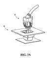
- the connector 34 comprises a set of contact elements 36A-36F, which, in the specific embodiment shown in Figure 3B, comprises six female contact elements 36A-36F in the form of pin receptacles that are made of an electrically conductive material.
- the contact elements 36A-36F are adapted to receive complementary contact elements 40A-40F, in the form of male pins, from the component connector 37.
- the contact elements 36A-36F are male contact elements
- the complementary contact elements 40A-40F are complementary female contact elements.
- the set of contact elements 36 of the controller connector 34 could include both female contact elements and male contact elements, in which case the complementary contact elements 40 of the component connector 37 would be designed accordingly.
- the set of contact elements 36 of the controller connector 34 are in the form of surface contact pads and the complementary contact elements 40A-40F are complementary surface contact pads adapted for establishing an electrical contact with corresponding contact elements 36 of the controller connector 34.
- the set of contact elements 36 includes one or more data link contacts, which can be in the form of low voltage control lines or serial link contacts for example, for allowing data to be exchanged between the controller 30 and a spa component through a controller connector 34. The data may be exchanged in digital or analog format. These additional data link contacts can be use to send instructions to a particular spa component.
- the controller 30 can also receive some data from the spa component. For example, speed control information may be sent to a pump and the pump can send an acknowledgement or a status message to the controller.
- the set of contact elements 36 of the connector 34 is arranged in a certain configuration that is common over connectors 34A-34G.
- the set of contact elements 36A-36F are arranged in a configuration that could be defined as a generally rectangular array of two rows by three columns.
- each contact element 36 in the set of contact elements 36A-36F of the connector 34 is provided with a particular voltage, current output or is connected to ground.
- the same particular voltage output or current output will be available at corresponding contact elements 36 of connectors 34A-34G.
- the same particular output will be available at the contact element 36A of each one of the connectors 34A-34G; the same particular output will be available at the contact element 36B of each one of the connectors 34A-34G; and so on.
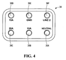
- Shown in Figure 4 is a configuration adapted for a North American 120/240 V single phase supply system, with a set of contact elements 36 of a connector 34 in accordance with a non-limiting example of implementation.
- Each one of the contact elements 36A-36F is provided with a certain voltage output, a certain current output or is connected to ground.
- this non-limiting embodiment :
- the contact elements 36 of the connector 34 are mounted to a contact element holder 46, which can be made of a suitable dielectric material such as a plastic, ceramic, or any composite material having substantially negligible electrical conductivity.
- the contact element holder 46 is adapted to be received in a connector housing 48.
- a seal or gasket 50 is disposed between the contact element holder 46 and the connector housing 48 for providing a fluid-tight and moisturetight interface between these two components.
- the seal 50 can be made, for example, of silicone rubber or any other suitable impermeable material. Seal 50 may be omitted from certain implementation where the risk the controller 30 will be in contact with water is very low however, in most spa implementations, the use of a seal 50 is preferred.
- the connector housing 48 may be formed integrally with a controller enclosure 52, only part of which is shown in dotted lines in Figure 3B. Alternatively, the connector housing 48 could be separate from controller enclosure 52 and may be mounted thereto using any suitable method.
- the connector housing 48 defines a receptacle 54 that is adapted to receive the contact element holder 46 at one end and to receive the component connector 37 associated with a spa component 35 at the other end.
- the receptacle 54 defined by the connector housing 48 has a common configuration for each one of the connectors 34 of the controller 30.
- the design and manufacturing of the controller enclosure 52 and the connector housings 48 is simplified.
- key member 38 is engaged in the connector housing 48. It will be appreciated, that the key member 38 can be made separately from the controller 30 such that it is adapted to engage the connector housing 48 at the end of the manufacturing of the controller 30. Furthermore, the key members 38 may be permanently engaged to the connectors 34 or, alternatively, they may be releasably engaged to the connectors 34. More specifically, the key member 38 depicted in figure 3b includes a tubular portion for slidingly engaging the receptacle 54 defined by the connector housing 48 and optionally a rim portion adapted for extending being the receptacle 54.
- the key member 38 when the key member 38 is engaged in the receptacle 54 defined by the connector housing 48 is may be permanently engaged therein or may be removable by sliding the key member 38 out of the receptacle.
- the rim portion may include descriptive indicia for facilitating the location of a spa component having a complementary key matching the key member 38.
- the inner wall of the tubular portion of key member 38 includes protrusions and/or notches in a certain pattern defining the key. The key member 38 will be described in greater detail later on in the specification.
- the component connector 37 comprises a main housing 72 that is made of an electrically non-conductive material and that is coupled to a cable 74 extending from a spa component 35.
- the main housing 72 is adapted to support a number of complementary contact elements 40.
- Each one of the contact elements 40 may be electrically connected to a conductor wire extending in the cable 74 to the spa component 35.
- the contact elements 40 are in the form of male pins that are made of an electrically conductive material, and that are adapted to mate with the contact elements 36 of the connector 34.
- each contact element 36 in the set of contact elements 36A-36F of connector 34 is associated with a certain voltage or current output. Accordingly, depending on the power requirements of a particular spa component 35, the component connector 37 associated with that particular spa component will only include certain ones of the complementary contact elements 40. In a non-limiting implementation, a particular component connector 37 will only include the certain contact elements 40 that correspond to the contact elements 36 of the connector 34 that are defined as the contact elements at which will be available voltage and current outputs corresponding to the power requirements of the spa component 35 associated with that particular connector 37. In an alternative implementation, the component connector 37 could include each one of the contact elements 40, but with the non-required contact elements 40 disabled, i.e. not connected to any internal conductor wires in the cable 74 extending from the spa component 35.
- FIG. 4 With reference to figures 6(a) to 6(h) and contact element 36 configuration shown in Figure 4, there are shown a number of examples illustrating subsets the contact elements 40A-40F in component connector 37 associated with a particular spa component 35 having operating voltage and current requirements.
- the contact elements 40 present in each example shown in Figures 6(a) to 6(h) represent an enabled contact element 40.
- Figure 6(a) shows that a spa component 35 having operating voltage and current requirements of 120 volts (V) and 15 amps (A), respectively, will have a component connector 37 that includes (or has enabled) contact elements 40A, 40D, and 40E.
- Figure 6(d) shows that another spa component 35 having operating voltage and current requirements of 240 volts (V) and 20 amps (A), respectively, will have a component connector 37 that includes (or has enabled) contact elements 40C, 40E, and 40F.
- the actual voltage and current that will be supplied to a particular spa component 35 will be determined by which ones of the contact elements 40 are present (or enabled) on the component connector 37 of that particular spa component 35. This allows for each one of the spa components 35 that is to be connected to the controller 30 to receive a power signal in accordance with its power requirements while allowing connectors 34 having a common contact element configuration to be used.
- complementary key member 39 is engaged with the main housing 72.
- the complementary key member 39 can be made separately from the component connectors 37 and may be adapted to engage the component connectors 37, either permanently or releasably, at the end of the manufacturing of the spa component 35 and component connector 37.
- the complementary key member 38 engages the outer surface of main housing 72. It will be appreciated that when the complementary key member 39 is engaged with the main housing 72 is may be permanently engaged therewith or may be removable therefrom.
- the complementary key member 38 may include descriptive indicia for facilitating the location of a connector having a key member 38 matching the complementary key member 39.
- the outer wall of the complementary key member 39 includes protrusions and/or notches in a certain pattern defining a complementary key to key member 38.
- the complementary key member 39 will be described in greater detail later on in the specification. It will be appreciated that certain embodiments may omit the complementary key member 39 and key member 38.
- a key member 38 can be added to a particular connector 34, and a complementary key member 39 that matches that key member 38 can be added to the component connector 37 of the spa component that is expected to connect to that particular connector 34. In this fashion, the connector 34 can be connected to the component connector 37 having the matching complementary key member 39.
- the contact elements 36 of the connector 34 are adapted to be electrically connected to a printed circuit board 42.
- the printed circuit board 42 receives power via service wiring 31 (shown in Figure 2) from a conventional electric power source 29.
- the printed circuit board 42 includes a variety of electrical components and patterns of printed wiring conductor traces that interconnect the variety of electrical components and the service wiring 31.
- Each one of the contact elements 36 may be directly connected to a respective one of the printed conductor traces, for example, by a soldered connection, or any other suitable method known in the art.
- each contact element 36 may be connected to a respective one of the printed conductor traces of the printed circuit board 42 via a respective conductor wire extending from the contact element to the printed conductor trace.
- the printed circuit board 42 is designed to either directly route, or convert and route directly or through a relay, the power received from service wiring 31 such as to achieve the particular voltage or current expected to be made available at each contact element 36 of the connector 34.
- the service wiring 31 includes a first line "line 1" , a second line "line 2", a Neutral and earth ground conductor connected to 120/240 V single phase supply system.
- the printed circuit board 42 includes a control circuit element connected to the variety of electrical components on the board and adapted to receive signals from various input devices of the spa system 10, such as the spa control panel 32 and various spa sensors 70 (shown in Figure 1).
- the control circuit element is adapted to control the operation of the various electrical components of the printed circuit board 42 on the basis of the signals received from the various input devices such as to enable or disable the particular voltage or current expected to be available at any one of the contact elements 36. For example, in a typical interaction, a user of the spa enters commands via the spa control panel 32 in order to activate a particular spa component.
- the control circuit element upon receiving signals generated by the control panel 32 on the basis of the entered commands, controls the various electrical components of the printed circuit board 42 such as to enable the connector 34 associated with the particular spa component 35.
- the control circuit element upon receiving the generated signal, could control the various electrical components of the printed circuit board 42 such as to disable the voltage and/or current available at the contact elements 36 of the connector 34 associated with the pump 12 or the heating module 60.
- control circuit element could be implemented by any suitable hardware and/or hardware/software combination without departing from the spirit and scope of the present invention.
- control circuit element is in the form of a microprocessor.
- control circuit element could be implemented by other suitable circuitry, including, by way of example only, an application-specific integrated circuit (ASIC), or discrete logic circuitry.
- ASIC application-specific integrated circuit
- the plurality of connectors 34 of the controller 30 may be connected to a single printed circuit board 42 or alternatively, each connector 34 of the controller 30 may be connected to a respective printed circuit board 42. In yet another alternative implementation, groups of connectors 34 are connected to a respective printed circuit board 42.
- the controller 30 is configured, through the design of the control circuit element, to associate each connector 34 to a particular spa component 35, such as a pump 12 or a heating module 60 (shown in Figure 1). Therefor, when a signal indicating that the pump 12 or heating module 60 should be turned off, the controller 30 is adapted to prevent the connector 34 corresponding to the spa component from providing electrical power to that spa component.
- the keying system including key member 38 and complementary key member may be used in combination with the connectors 34 in order to specify a connection pattern for the spa components. More specifically, a key member 38 can be added to a particular connector 34, and a complementary key member 39 that matches that key member 38 can be added to the component connector 37 of the spa component that is expected to connect to that particular connector 34. In this fashion, the connector 34 can be connected to the component connector 37 having the matching complementary key member 39.
- the keying system is designed such as to prevent the connector 34 from being connected to a component connector 37 having a non-matching component key member 39.
- the key member 38 of a particular connector 34 ensures that only a particular spa component 35 that is expected to be electrically connected to that particular connector 34 can be connected to that particular connector 34.
- the key member 38 of a particular connector 34 that is expected, by way of configuration of the controller 30, to be connected to a pump of the spa system 10 will only allow a pump having a component connector 37 with a matching complementary key member 39 to be connected to that connector 34, and will prevent any other type of spa component 35 from being connected to that connector 34.
- FIGS 5A to 5H illustrate a set of possible designs for the key members 38 and the complementary key members 39, in accordance with specific examples of implementation of the present invention.
- Each key member 38 and each complementary key member 39 includes a respective body including a particular combination of protrusions 62 and/or grooves 64.
- the key member 38 that includes the grooves 64 and the complementary key member 39 that includes the protrusions 62.
- the key member 38 could include the protrusions 62 and the complementary key member 39 could include the grooves 64.
- the key member 38 and the complementary key member 39 could each include a combination of protrusions 62 and grooves 64.
- the pattern of grooves 64 on the key member 38 corresponds to the pattern of protrusions 62 on the complementary key member 39.
- a particular complementary key member 39 will match a key member 38 if their respective protrusions 62 and grooves 64 match in a complementary manner.
- each type of spa component 35 is provided with a key member 38 and complementary key member 39 that are different from the key members 38 and complementary key members 39 associated with other types of spa component 35. That is, a particular key member 38 design and a matching complementary key member 39 design are assigned to a pump; another particular key member 38 design and a matching complementary key member 39 design are assigned to a heating module; and so on.
- each key member 38 and matching complementary key member 39 may be produced in a distinct color and/or include a distinct indicia marking, in order to further facilitate ease of connection between the connectors 34 and component connectors 37.
- the indicia marking includes a set of alpha-numeric characters, one or more symbols or drawings or any other suitable indicia to further facilitate ease of connection between the connectors 34 and component connectors 37.
- the keying system shown in 5c includes the indicia "PUMP #1"; the keying system shown in 5d includes the indicia "PUMP #2”; the keying system shown in 5e includes the indicia "HEATING MODULE" and so on.
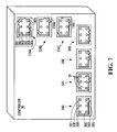
- Figure 7 shows a possible variant of a controller 30 in accordance with another specific example of implementation of the present invention.
- the controller 30 includes a first set of connectors 34A-34D and a second set of connectors 134A-134C, which are both implemented in accordance with the principles of the present invention.
- Each connector of the first set of connectors 34A-34D includes a set of contact elements 36 arranged in a certain configuration and having a voltage or current output available at each contact element 36 that is common over all of the connectors 34A-34D.
- each connector 134A-134Cof the second plurality of connectors 134 also includes a set of contact elements 136 arranged in a certain configuration and having a voltage or current output available at each contact element 136 that is common over all of the connectors 134A-134C.
- the voltage or current output available at each contact element 36 of each connector of the first plurality of connectors 34A-34D is different from the voltage or current output available at each contact element 136 of each connector 134 of the second plurality of connectors 134A-134C.
- the voltage or current output available at each contact element 36 of each connector of the first plurality of connectors 34A-34D could be as defined above in connection with Figure 4.
- the voltage or current output available at each contact element 136 of each connector of the second plurality of connectors 134A-134Ccould be defined as shown in Figure 8.
- the contact element is a terminal at which an output voltage of 120 volts (V) is available;
- the contact element 136B is a terminal at which an output current of 5 amps (A) is available;
- the contact element 136C is a terminal at which another output current of 10 amps (A) is available;
- the contact element 136D is a terminal at which an output current of 5 amps (A) is available;
- the contact element 136E is a ground terminal;
- the contact element 136F is a terminal at which an output voltage of 240 volts (V) is available.
- the connectors 34A-34D may be defined as a high-current connector suitable to be connected with a spa component 35 such as a pump 12 or a blower 24 ( Figure 1), while the connectors 134A-134C may be defined as a low-current connector suitable to be connected with other spa components such as ozonator and small circulating pump.
- a controller 30 including first and second pluralities of connectors 34 and 134, respectively, it is to be understood that the controller could include any number of pluralities of connectors each with a respective contact element definition set.
- the configuration of the contact elements and/or the number of contact elements may be different in the first plurality of connectors 34A-34D and in the second plurality of connectors 134A-134C without detracting from the spirit of the invention.
Landscapes
- Details Of Connecting Devices For Male And Female Coupling (AREA)
- Electrotherapy Devices (AREA)
- Devices For Medical Bathing And Washing (AREA)
Applications Claiming Priority (2)
| Application Number | Priority Date | Filing Date | Title |
|---|---|---|---|
| US693868 | 2003-10-28 | ||
| US10/693,868 US6929516B2 (en) | 2003-10-28 | 2003-10-28 | Bathing unit controller and connector system therefore |
Publications (2)
| Publication Number | Publication Date |
|---|---|
| EP1527764A2 true EP1527764A2 (de) | 2005-05-04 |
| EP1527764A3 EP1527764A3 (de) | 2005-07-13 |
Family
ID=34423331
Family Applications (1)
| Application Number | Title | Priority Date | Filing Date |
|---|---|---|---|
| EP04292314A Withdrawn EP1527764A3 (de) | 2003-10-28 | 2004-09-28 | Steuerung und Anschlusssystem für eine Badeeinheit |
Country Status (3)
| Country | Link |
|---|---|
| US (2) | US6929516B2 (de) |
| EP (1) | EP1527764A3 (de) |
| CA (1) | CA2483876C (de) |
Cited By (3)
| Publication number | Priority date | Publication date | Assignee | Title |
|---|---|---|---|---|
| WO2014127956A1 (de) * | 2013-02-25 | 2014-08-28 | Phoenix Contact Gmbh & Co Kg | Kontaktträger mit einer isolierhülse |
| EP3148014A1 (de) * | 2015-09-23 | 2017-03-29 | Hamilton Sundstrand Corporation | Elektrische verbinderanordnungen |
| JP2017191674A (ja) * | 2016-04-12 | 2017-10-19 | 住友電装株式会社 | 基板用コネクタ |
Families Citing this family (111)
| Publication number | Priority date | Publication date | Assignee | Title |
|---|---|---|---|---|
| US6117144A (en) * | 1995-08-24 | 2000-09-12 | Sutura, Inc. | Suturing device and method for sealing an opening in a blood vessel or other biological structure |
| US9153960B2 (en) | 2004-01-15 | 2015-10-06 | Comarco Wireless Technologies, Inc. | Power supply equipment utilizing interchangeable tips to provide power and a data signal to electronic devices |
| US7327275B2 (en) * | 2004-02-02 | 2008-02-05 | Gecko Alliance Group Inc. | Bathing system controller having abnormal operational condition identification capabilities |
| US6976885B2 (en) * | 2004-03-02 | 2005-12-20 | Mobility Electronics, Inc. | Keyed universal power tip and power source connectors |
| US7056149B1 (en) * | 2004-11-12 | 2006-06-06 | Comarco Wireless Technologies, Inc. | Key coded power adapter connectors |
| US7619181B2 (en) * | 2005-07-12 | 2009-11-17 | Gecko Alliance Group Inc. | Heating system for bathing unit |
| US7642671B2 (en) * | 2006-04-28 | 2010-01-05 | Acco Brands Usa Llc | Power supply system providing two output voltages |
| US7390210B2 (en) * | 2006-11-08 | 2008-06-24 | Dsm&T Company Inc. | Electrical connector with high impact strength locking assemblies |
| US7904830B2 (en) | 2006-11-30 | 2011-03-08 | Honeywell International Inc. | HVAC zone control panel |
| CA2658372C (en) | 2009-03-13 | 2016-09-27 | G.B.D. Corp. | Surface cleaning apparatus |
| US12220099B2 (en) | 2006-12-12 | 2025-02-11 | Omachron Intellectual Property Inc. | Surface cleaning apparatus |
| CA2599303A1 (en) | 2007-08-29 | 2009-02-28 | Gbd Corp. | Surface cleaning apparatus |
| US10165912B2 (en) | 2006-12-15 | 2019-01-01 | Omachron Intellectual Property Inc. | Surface cleaning apparatus |
| US9888817B2 (en) | 2014-12-17 | 2018-02-13 | Omachron Intellectual Property Inc. | Surface cleaning apparatus |
| US9192269B2 (en) | 2006-12-15 | 2015-11-24 | Omachron Intellectual Property Inc. | Surface cleaning apparatus |
| US11857142B2 (en) | 2006-12-15 | 2024-01-02 | Omachron Intellectual Property Inc. | Surface cleaning apparatus having an energy storage member and a charger for an energy storage member |
| US20210401246A1 (en) | 2016-04-11 | 2021-12-30 | Omachron Intellectual Property Inc. | Surface cleaning apparatus |
| US7957839B2 (en) * | 2006-12-29 | 2011-06-07 | Honeywell International Inc. | HVAC zone controller |
| US8104110B2 (en) * | 2007-01-12 | 2012-01-31 | Gecko Alliance Group Inc. | Spa system with flow control feature |
| JP4899923B2 (ja) * | 2007-02-23 | 2012-03-21 | 東洋製罐株式会社 | 熱可塑性樹脂から成る層を有する部材の溶着方法及び蓋付熱可塑性樹脂容器 |
| CA2952801A1 (en) * | 2007-02-26 | 2008-08-26 | Groupe Gecko Alliance Inc. | Auxiliary device for providing multimedia functionality to bathing unit system |
| WO2008104056A1 (en) * | 2007-02-26 | 2008-09-04 | Groupe Gecko Alliance Inc. | A method, device and system for use in configuring a bathing unit controller |
| US11751733B2 (en) | 2007-08-29 | 2023-09-12 | Omachron Intellectual Property Inc. | Portable surface cleaning apparatus |
| US12048409B2 (en) | 2007-03-11 | 2024-07-30 | Omachron Intellectual Property Inc. | Portable surface cleaning apparatus |
| US8112164B2 (en) * | 2007-09-27 | 2012-02-07 | Balboa Instruments, Inc. | Low maintenance spa control system |
| AT506058B1 (de) * | 2008-04-11 | 2009-05-15 | Biotop Landschaftsgestaltung G | Verfahren und vorrichtung zur biologischen aufbereitung von wasser in schwimmbecken |
| DE102009031287A1 (de) * | 2008-06-30 | 2010-01-21 | Hirschmann Automotive Gmbh | Mehrteilige Gehäuse-Steckkontaktierung |
| TWI359650B (en) * | 2008-12-24 | 2012-03-11 | Dartpoint Tech Co Ltd | Massage bathtub automatic control system and metho |
| WO2010102394A1 (en) | 2009-03-11 | 2010-09-16 | G.B.D. Corp. | Hand vacuum cleaner with removable dirt chamber |
| US9211044B2 (en) | 2011-03-04 | 2015-12-15 | Omachron Intellectual Property Inc. | Compact surface cleaning apparatus |
| US12156626B2 (en) | 2009-03-13 | 2024-12-03 | Omachron Intellectual Property Inc. | Surface cleaning apparatus |
| US9265395B2 (en) | 2010-03-12 | 2016-02-23 | Omachron Intellectual Property Inc. | Surface cleaning apparatus |
| US10722086B2 (en) | 2017-07-06 | 2020-07-28 | Omachron Intellectual Property Inc. | Handheld surface cleaning apparatus |
| US9138114B2 (en) | 2009-03-13 | 2015-09-22 | Omachron Intellectual Property Inc. | Surface cleaning apparatus |
| US9433332B2 (en) | 2013-02-27 | 2016-09-06 | Omachron Intellectual Property Inc. | Surface cleaning apparatus |
| US11690489B2 (en) | 2009-03-13 | 2023-07-04 | Omachron Intellectual Property Inc. | Surface cleaning apparatus with an external dirt chamber |
| US8354760B2 (en) | 2009-10-28 | 2013-01-15 | Comarco Wireless Technologies, Inc. | Power supply equipment to simultaneously power multiple electronic device |
| CA2684820A1 (en) | 2009-11-06 | 2011-05-06 | Wayne Ernest Conrad | Electrical cord and apparatus using same |
| US8644960B2 (en) | 2010-10-22 | 2014-02-04 | Gecko Alliance Group Inc. | Method and system for providing ambiance settings in a bathing system |
| US8612061B2 (en) | 2010-10-22 | 2013-12-17 | Gecko Alliance Group Inc. | Method and system for controlling a bathing system in accordance with an energy savings mode |
| US8973214B2 (en) | 2011-03-03 | 2015-03-10 | G.B.D. Corp. | Cyclone chamber and dirt collection assembly for a surface cleaning apparatus |
| US8978198B2 (en) | 2011-03-03 | 2015-03-17 | G.B.D. Corp. | Filter housing for a surface cleaning apparatus |
| US8769767B2 (en) | 2011-03-03 | 2014-07-08 | G.B.D. Corp. | Removable cyclone chamber and dirt collection assembly for a surface cleaning apparatus |
| US8813306B2 (en) | 2011-03-03 | 2014-08-26 | G.B.D. Corp. | Openable side compartments for a surface cleaning apparatus |
| US9101252B2 (en) | 2011-03-03 | 2015-08-11 | G.B.D. Corp. | Configuration of a surface cleaning apparatus |
| US8973212B2 (en) | 2011-03-03 | 2015-03-10 | G.B.D. Corp. | Filter housing construction for a surface cleaning apparatus |
| US8763202B2 (en) | 2011-03-03 | 2014-07-01 | G.B.D. Corp. | Cyclone chamber and dirt collection assembly for a surface cleaning apparatus |
| US8739357B2 (en) | 2011-03-03 | 2014-06-03 | G.B.D. Corp | Filter construction for a surface cleaning apparatus |
| US8646149B2 (en) | 2011-03-03 | 2014-02-11 | G.B.D. Corp. | Filter housing construction for a surface cleaning apparatus |
| US8739359B2 (en) | 2011-03-03 | 2014-06-03 | G.B.D. Corp. | Configuration of a surface cleaning apparatus |
| US8869345B2 (en) | 2011-03-03 | 2014-10-28 | G.B.D. Corp. | Canister vacuum cleaner |
| US8601641B2 (en) | 2011-03-04 | 2013-12-10 | G.B.D. Corp. | Removable cyclone chamber and dirt collection assembly for a surface cleaning apparatus |
| US9232881B2 (en) | 2011-03-04 | 2016-01-12 | Omachron Intellectual Property Inc. | Surface cleaning apparatus with removable handle assembly |
| US8646146B2 (en) | 2011-03-04 | 2014-02-11 | G.B.D. Corp. | Suction hose wrap for a surface cleaning apparatus |
| US8689395B2 (en) | 2011-03-04 | 2014-04-08 | G.B.D. Corp. | Portable surface cleaning apparatus |
| US8683644B2 (en) | 2011-03-04 | 2014-04-01 | G.B.D. | Automatic cord release |
| ITVI20110265A1 (it) * | 2011-10-04 | 2013-04-05 | Tyco Electronics Amp Italia Srl | Alloggiamento per connettore |
| CN103529919A (zh) * | 2012-07-05 | 2014-01-22 | 鸿富锦精密工业(深圳)有限公司 | 服务器扩展电路及服务器系统 |
| US9027198B2 (en) | 2013-02-27 | 2015-05-12 | G.B.D. Corp. | Surface cleaning apparatus |
| US9591958B2 (en) | 2013-02-27 | 2017-03-14 | Omachron Intellectual Property Inc. | Surface cleaning apparatus |
| US9320401B2 (en) | 2013-02-27 | 2016-04-26 | Omachron Intellectual Property Inc. | Surface cleaning apparatus |
| US9204773B2 (en) | 2013-03-01 | 2015-12-08 | Omachron Intellectual Property Inc. | Surface cleaning apparatus |
| US9427126B2 (en) | 2013-03-01 | 2016-08-30 | Omachron Intellectual Property Inc. | Surface cleaning apparatus |
| US9161669B2 (en) | 2013-03-01 | 2015-10-20 | Omachron Intellectual Property Inc. | Surface cleaning apparatus |
| US20140237768A1 (en) | 2013-02-28 | 2014-08-28 | G.B.D. Corp. | Surface cleaning apparatus |
| WO2014143779A2 (en) | 2013-03-15 | 2014-09-18 | Hayward Industries, Inc | Modular pool/spa control system |
| US9974709B2 (en) | 2014-02-18 | 2018-05-22 | Nuwhirl Systems Corporation | Nozzles |
| US9445482B2 (en) | 2014-05-23 | 2016-09-13 | Gecko Alliance Group Inc. | Light bulb and method and system for use in configuring same |
| US9641959B2 (en) | 2014-05-23 | 2017-05-02 | Gecko Alliance Group Inc. | Household for industrial device including programmable controller and method device and system for use in configuring same |
| US9420925B2 (en) | 2014-07-18 | 2016-08-23 | Omachron Intellectual Property Inc. | Portable surface cleaning apparatus |
| US9451853B2 (en) | 2014-07-18 | 2016-09-27 | Omachron Intellectual Property Inc. | Portable surface cleaning apparatus |
| US9585530B2 (en) | 2014-07-18 | 2017-03-07 | Omachron Intellectual Property Inc. | Portable surface cleaning apparatus |
| US9314139B2 (en) | 2014-07-18 | 2016-04-19 | Omachron Intellectual Property Inc. | Portable surface cleaning apparatus |
| US10136778B2 (en) | 2014-12-17 | 2018-11-27 | Omachron Intellectual Property Inc. | Surface cleaning apparatus |
| US11950745B2 (en) | 2014-12-17 | 2024-04-09 | Omachron Intellectual Property Inc. | Surface cleaning apparatus |
| US10251519B2 (en) | 2014-12-17 | 2019-04-09 | Omachron Intellectual Property Inc. | Surface cleaning apparatus |
| DE102016107500A1 (de) * | 2016-04-22 | 2017-10-26 | Beko Technologies Gmbh | Baugruppe für einen Kondensatableiter zum Ableiten eines Druckgaskondensats |
| US10159624B2 (en) | 2015-09-11 | 2018-12-25 | Gecko Alliance Group Inc. | Method for facilitating control of a bathing unit system and control panel implementing same |
| US11720085B2 (en) | 2016-01-22 | 2023-08-08 | Hayward Industries, Inc. | Systems and methods for providing network connectivity and remote monitoring, optimization, and control of pool/spa equipment |
| EP3405629A4 (de) | 2016-01-22 | 2020-01-22 | Hayward Industries, Inc. | Systeme und verfahren zur bereitstellung von netzwerkkonnektivität und fernüberwachung, optimierung und steuerung einer pool-/spa-ausrüstung |
| US10321794B2 (en) | 2016-08-29 | 2019-06-18 | Omachron Intellectual Property Inc. | Surface cleaning apparatus |
| US10136780B2 (en) | 2016-08-29 | 2018-11-27 | Omachron Intellectual Property Inc. | Surface cleaning apparatus |
| US10292550B2 (en) | 2016-08-29 | 2019-05-21 | Omachron Intellectual Property Inc. | Surface cleaning apparatus |
| US9962050B2 (en) | 2016-08-29 | 2018-05-08 | Omachron Intellectual Property Inc. | Surface cleaning apparatus |
| US10136779B2 (en) | 2016-08-29 | 2018-11-27 | Omachron Intellectual Property Inc. | Surface cleaning apparatus |
| US10441124B2 (en) | 2016-08-29 | 2019-10-15 | Omachron Intellectual Property Inc. | Surface cleaning apparatus |
| US10405711B2 (en) | 2016-08-29 | 2019-09-10 | Omachron Intellectual Property Inc. | Surface cleaning apparatus |
| US10433689B2 (en) | 2016-08-29 | 2019-10-08 | Omachron Intellectual Property Inc. | Surface cleaning apparatus |
| US11478117B2 (en) | 2016-08-29 | 2022-10-25 | Omachron Intellectual Property Inc. | Surface cleaning apparatus |
| US10729295B2 (en) | 2016-08-29 | 2020-08-04 | Omachron Intellectual Property Inc. | Surface cleaning apparatus |
| US10441125B2 (en) | 2016-08-29 | 2019-10-15 | Omachron Intellectual Property Inc. | Surface cleaning apparatus |
| US10413141B2 (en) | 2016-08-29 | 2019-09-17 | Omachron Intellectual Property Inc. | Surface cleaning apparatus |
| US10228359B2 (en) | 2017-03-16 | 2019-03-12 | Gecko Alliance Group Inc. | Method, device and apparatus for monitoring halogen levels in a body of water |
| US10506904B2 (en) | 2017-07-06 | 2019-12-17 | Omachron Intellectual Property Inc. | Handheld surface cleaning apparatus |
| US10631693B2 (en) | 2017-07-06 | 2020-04-28 | Omachron Intellectual Property Inc. | Handheld surface cleaning apparatus |
| US10702113B2 (en) | 2017-07-06 | 2020-07-07 | Omachron Intellectual Property Inc. | Handheld surface cleaning apparatus |
| US11666193B2 (en) | 2020-03-18 | 2023-06-06 | Omachron Intellectual Property Inc. | Surface cleaning apparatus with removable air treatment member assembly |
| US11445878B2 (en) | 2020-03-18 | 2022-09-20 | Omachron Intellectual Property Inc. | Surface cleaning apparatus with removable air treatment member assembly |
| US10750913B2 (en) | 2017-07-06 | 2020-08-25 | Omachron Intellectual Property Inc. | Handheld surface cleaning apparatus |
| US11766156B2 (en) | 2020-03-18 | 2023-09-26 | Omachron Intellectual Property Inc. | Surface cleaning apparatus with removable air treatment member assembly |
| US10842330B2 (en) | 2017-07-06 | 2020-11-24 | Omachron Intellectual Property Inc. | Handheld surface cleaning apparatus |
| US10537216B2 (en) | 2017-07-06 | 2020-01-21 | Omachron Intellectual Property Inc. | Handheld surface cleaning apparatus |
| US11730327B2 (en) | 2020-03-18 | 2023-08-22 | Omachron Intellectual Property Inc. | Surface cleaning apparatus with removable air treatment assembly |
| US11930987B2 (en) | 2018-04-20 | 2024-03-19 | Omachron Intellectual Property Inc. | Surface cleaning apparatus |
| US11116692B2 (en) | 2018-06-07 | 2021-09-14 | Gecko Alliance Group Inc. | Method, system, computer program product and device for facilitating centralized control and monitoring over a network of a set of remote bathing unit systems |
| JP7128686B2 (ja) * | 2018-08-07 | 2022-08-31 | 日本航空電子工業株式会社 | コネクタ |
| US11192122B2 (en) | 2018-08-13 | 2021-12-07 | Omachron Intellectual Property Inc. | Cyclonic air treatment member and surface cleaning apparatus including the same |
| US11013384B2 (en) | 2018-08-13 | 2021-05-25 | Omachron Intellectual Property Inc. | Cyclonic air treatment member and surface cleaning apparatus including the same |
| US11006799B2 (en) | 2018-08-13 | 2021-05-18 | Omachron Intellectual Property Inc. | Cyclonic air treatment member and surface cleaning apparatus including the same |
| JP7313991B2 (ja) * | 2019-09-09 | 2023-07-25 | 日本航空電子工業株式会社 | コネクタ |
| US20210386258A1 (en) | 2020-03-18 | 2021-12-16 | Omachron Intellectual Property Inc. | Surface cleaning apparatus |
Family Cites Families (29)
| Publication number | Priority date | Publication date | Assignee | Title |
|---|---|---|---|---|
| US2720038A (en) * | 1952-09-15 | 1955-10-11 | Lewis H Clark | Toy |
| GB930509A (en) | 1960-06-17 | 1963-07-03 | Painton & Co Ltd | Improvements in or relating to electrical connectors |
| US3085221A (en) * | 1960-09-27 | 1963-04-09 | Cannon Electric Co | Connector with selectivity key |
| US3609636A (en) * | 1969-01-28 | 1971-09-28 | Bunker Ramo | Electrical connectors |
| US4296992A (en) * | 1977-09-26 | 1981-10-27 | Bunker Ramo Corporation | Electrical connector assembly |
| US4159862A (en) * | 1977-12-12 | 1979-07-03 | Fabri-Tek Incorporated | Removable female polarizing guide for electrical connectors |
| JPS5722710Y2 (de) * | 1978-10-05 | 1982-05-17 | ||
| EP0033286A3 (de) | 1980-01-28 | 1981-10-28 | The Bendix Corporation | Polarisationsmittel für zusammenfügbare Einheiten, wie z.B. elektrische Verbinder |
| US4386333A (en) * | 1981-11-02 | 1983-05-31 | International Business Machines Corporation | Universal electrical connection apparatus |
| US4758174A (en) * | 1987-01-20 | 1988-07-19 | Molex Incorporated | Environmentally sealed electrical connector |
| US5245221A (en) * | 1989-10-23 | 1993-09-14 | American Standard Inc. | System for jetted tubs and apparatus therefor |
| US5254019A (en) * | 1992-07-08 | 1993-10-19 | Burndy Corporation | Configurable coded electrical plug and socket |
| GB9306881D0 (en) * | 1993-04-01 | 1993-05-26 | Strix Ltd | Electrical coupling |
| US5401181A (en) * | 1993-04-15 | 1995-03-28 | D S M & T Co., Inc. | Connector with fluid sealing |
| US5421746A (en) * | 1993-09-13 | 1995-06-06 | Berg Technology, Inc. | Orientation and positioning device for electrical connectors |
| US5370556A (en) * | 1993-09-20 | 1994-12-06 | The Whitaker Corporation | Keying system for electrical connectors |
| US5685727A (en) * | 1995-01-20 | 1997-11-11 | Ocean Design, Inc. | Underwater mateable connector |
| US5733148A (en) * | 1996-04-04 | 1998-03-31 | The Whitaker Corporation | Electrical connector with programmable keying system |
| US5844763A (en) * | 1997-01-17 | 1998-12-01 | The Wiremold Company | Electrical outlet assembly having field replaceable transient voltage surge suppression module |
| US6218846B1 (en) * | 1997-08-01 | 2001-04-17 | Worcester Polytechnic Institute | Multi-probe impedance measurement system and method for detection of flaws in conductive articles |
| US6128196A (en) * | 1998-04-27 | 2000-10-03 | Stratus Computer, Inc. | Circuit board chassis |
| US6407469B1 (en) * | 1999-11-30 | 2002-06-18 | Balboa Instruments, Inc. | Controller system for pool and/or spa |
| JP2001210409A (ja) * | 2000-01-28 | 2001-08-03 | Yazaki Corp | フラット回路体用のコネクタ及びフラット回路体のコネクタへの接続構造 |
| US6379169B1 (en) * | 2000-08-07 | 2002-04-30 | Dsm & T Co. Inc. | Electrical plug housing |
| US6495931B2 (en) * | 2001-01-10 | 2002-12-17 | California Acrylic Industries | Modular controller housing for water pool apparatus |
| DE10113223A1 (de) | 2001-03-19 | 2002-10-02 | Siemens Ag | Steuerungssystem für Sprudelbäder |
| US6540549B2 (en) * | 2001-06-14 | 2003-04-01 | Dekko Engineering, Inc. | Keyed power cord |
| US7030343B2 (en) * | 2002-10-03 | 2006-04-18 | Balboa Instruments, Inc. | Controller system for bathing installation |
| US6752665B2 (en) * | 2002-11-18 | 2004-06-22 | Trompeter Electronics, Inc. | Modular cross-connect with removable switch assembly |
-
2003
- 2003-10-28 US US10/693,868 patent/US6929516B2/en not_active Expired - Lifetime
-
2004
- 2004-09-28 EP EP04292314A patent/EP1527764A3/de not_active Withdrawn
- 2004-10-06 CA CA 2483876 patent/CA2483876C/en not_active Expired - Fee Related
-
2005
- 2005-03-07 US US11/072,335 patent/US7419406B2/en not_active Expired - Lifetime
Non-Patent Citations (1)
| Title |
|---|
| None |
Cited By (4)
| Publication number | Priority date | Publication date | Assignee | Title |
|---|---|---|---|---|
| WO2014127956A1 (de) * | 2013-02-25 | 2014-08-28 | Phoenix Contact Gmbh & Co Kg | Kontaktträger mit einer isolierhülse |
| EP3148014A1 (de) * | 2015-09-23 | 2017-03-29 | Hamilton Sundstrand Corporation | Elektrische verbinderanordnungen |
| US9728897B2 (en) | 2015-09-23 | 2017-08-08 | Hamilton Sundstrand Corporation | Power connector assemblies |
| JP2017191674A (ja) * | 2016-04-12 | 2017-10-19 | 住友電装株式会社 | 基板用コネクタ |
Also Published As
| Publication number | Publication date |
|---|---|
| US20050090153A1 (en) | 2005-04-28 |
| EP1527764A3 (de) | 2005-07-13 |
| CA2483876C (en) | 2009-04-07 |
| US6929516B2 (en) | 2005-08-16 |
| CA2483876A1 (en) | 2005-04-28 |
| US7419406B2 (en) | 2008-09-02 |
| US20050151425A1 (en) | 2005-07-14 |
Similar Documents
| Publication | Publication Date | Title |
|---|---|---|
| CA2483876C (en) | Bathing unit controller and connector system therefore | |
| EP3074875B1 (de) | Elektrische steckverbinder | |
| KR101174730B1 (ko) | 대기전력제어를 위한 지능형 콘센트 | |
| DE69813789D1 (de) | Elektrisch beheiztes Zerstäubungssystem von chemischen Wirkstoffen sowie ein Verfahren zu dessen Herstellung | |
| JP2767160B2 (ja) | 自動車の電気装置用制御装置 | |
| EP0137560B1 (de) | Zugabevorrichtung für Flüssigkeiten | |
| CA2499551C (en) | Bathing unit controller | |
| US6240249B1 (en) | Electric water heater with simplified phase conversion apparatus | |
| CN213554893U (zh) | 颈部按摩仪 | |
| WO2016072795A2 (ko) | 콘센트 | |
| CN1238064A (zh) | 插接座位编码装置 | |
| CN218770298U (zh) | 一种安全防水插座 | |
| KR20190065523A (ko) | 터치 입력장치 | |
| EP4568027A1 (de) | Verteilervorrichtung und stromversorgungssystem mit dieser verteilervorrichtung | |
| CN107715287B (zh) | 一种多功能美容器 | |
| US5436799A (en) | Modular switching-element block | |
| CN101901969B (zh) | 具有终端模块的自动化设备 | |
| KR101341622B1 (ko) | 인터커넥팅 장치 | |
| CN209058779U (zh) | 一种烹饪器具 | |
| KR101401724B1 (ko) | 복합하우징을 구비한 냉장고용 피시비 | |
| KR101053587B1 (ko) | 세탁기의 원격제어용 기판 어셈블리 | |
| US20120127645A1 (en) | Functional module for mounting on a mounting platform of a switch cabinet | |
| US6495931B2 (en) | Modular controller housing for water pool apparatus | |
| CN217468942U (zh) | 转接连接器 | |
| KR890000537Y1 (ko) | 가정용 전원과 자동차전원겸용 전기포트 |
Legal Events
| Date | Code | Title | Description |
|---|---|---|---|
| PUAI | Public reference made under article 153(3) epc to a published international application that has entered the european phase |
Free format text: ORIGINAL CODE: 0009012 |
|
| AK | Designated contracting states |
Kind code of ref document: A2 Designated state(s): AT BE BG CH CY CZ DE DK EE ES FI FR GB GR HU IE IT LI LU MC NL PL PT RO SE SI SK TR |
|
| AX | Request for extension of the european patent |
Extension state: AL HR LT LV MK |
|
| PUAL | Search report despatched |
Free format text: ORIGINAL CODE: 0009013 |
|
| AK | Designated contracting states |
Kind code of ref document: A3 Designated state(s): AT BE BG CH CY CZ DE DK EE ES FI FR GB GR HU IE IT LI LU MC NL PL PT RO SE SI SK TR |
|
| AX | Request for extension of the european patent |
Extension state: AL HR LT LV MK |
|
| 17P | Request for examination filed |
Effective date: 20060103 |
|
| AKX | Designation fees paid |
Designated state(s): DE FR GB IT |
|
| RAP1 | Party data changed (applicant data changed or rights of an application transferred) |
Owner name: GROUPE GECKO ALLIANCE INC. |
|
| 17Q | First examination report despatched |
Effective date: 20071011 |
|
| STAA | Information on the status of an ep patent application or granted ep patent |
Free format text: STATUS: THE APPLICATION IS DEEMED TO BE WITHDRAWN |
|
| 18D | Application deemed to be withdrawn |
Effective date: 20120320 |