EP1527672A2 - Tondeuse à fil de coupe munie d'un manche rabattable - Google Patents
Tondeuse à fil de coupe munie d'un manche rabattable Download PDFInfo
- Publication number
- EP1527672A2 EP1527672A2 EP05002231A EP05002231A EP1527672A2 EP 1527672 A2 EP1527672 A2 EP 1527672A2 EP 05002231 A EP05002231 A EP 05002231A EP 05002231 A EP05002231 A EP 05002231A EP 1527672 A2 EP1527672 A2 EP 1527672A2
- Authority
- EP
- European Patent Office
- Prior art keywords
- neck
- coupling
- assembly
- recess
- coupling recess
- Prior art date
- Legal status (The legal status is an assumption and is not a legal conclusion. Google has not performed a legal analysis and makes no representation as to the accuracy of the status listed.)
- Granted
Links
Images

Classifications
-
- B—PERFORMING OPERATIONS; TRANSPORTING
- B25—HAND TOOLS; PORTABLE POWER-DRIVEN TOOLS; MANIPULATORS
- B25F—COMBINATION OR MULTI-PURPOSE TOOLS NOT OTHERWISE PROVIDED FOR; DETAILS OR COMPONENTS OF PORTABLE POWER-DRIVEN TOOLS NOT PARTICULARLY RELATED TO THE OPERATIONS PERFORMED AND NOT OTHERWISE PROVIDED FOR
- B25F5/00—Details or components of portable power-driven tools not particularly related to the operations performed and not otherwise provided for
- B25F5/02—Construction of casings, bodies or handles
-
- A—HUMAN NECESSITIES
- A01—AGRICULTURE; FORESTRY; ANIMAL HUSBANDRY; HUNTING; TRAPPING; FISHING
- A01D—HARVESTING; MOWING
- A01D34/00—Mowers; Mowing apparatus of harvesters
- A01D34/006—Control or measuring arrangements
-
- A—HUMAN NECESSITIES
- A01—AGRICULTURE; FORESTRY; ANIMAL HUSBANDRY; HUNTING; TRAPPING; FISHING
- A01D—HARVESTING; MOWING
- A01D34/00—Mowers; Mowing apparatus of harvesters
- A01D34/835—Mowers; Mowing apparatus of harvesters specially adapted for particular purposes
- A01D34/90—Mowers; Mowing apparatus of harvesters specially adapted for particular purposes for carrying by the operator
-
- Y—GENERAL TAGGING OF NEW TECHNOLOGICAL DEVELOPMENTS; GENERAL TAGGING OF CROSS-SECTIONAL TECHNOLOGIES SPANNING OVER SEVERAL SECTIONS OF THE IPC; TECHNICAL SUBJECTS COVERED BY FORMER USPC CROSS-REFERENCE ART COLLECTIONS [XRACs] AND DIGESTS
- Y10—TECHNICAL SUBJECTS COVERED BY FORMER USPC
- Y10S—TECHNICAL SUBJECTS COVERED BY FORMER USPC CROSS-REFERENCE ART COLLECTIONS [XRACs] AND DIGESTS
- Y10S56/00—Harvesters
- Y10S56/18—Handles
-
- Y—GENERAL TAGGING OF NEW TECHNOLOGICAL DEVELOPMENTS; GENERAL TAGGING OF CROSS-SECTIONAL TECHNOLOGIES SPANNING OVER SEVERAL SECTIONS OF THE IPC; TECHNICAL SUBJECTS COVERED BY FORMER USPC CROSS-REFERENCE ART COLLECTIONS [XRACs] AND DIGESTS
- Y10—TECHNICAL SUBJECTS COVERED BY FORMER USPC
- Y10T—TECHNICAL SUBJECTS COVERED BY FORMER US CLASSIFICATION
- Y10T403/00—Joints and connections
- Y10T403/16—Joints and connections with adjunctive protector, broken parts retainer, repair, assembly or disassembly feature
- Y10T403/1616—Position or guide means
-
- Y—GENERAL TAGGING OF NEW TECHNOLOGICAL DEVELOPMENTS; GENERAL TAGGING OF CROSS-SECTIONAL TECHNOLOGIES SPANNING OVER SEVERAL SECTIONS OF THE IPC; TECHNICAL SUBJECTS COVERED BY FORMER USPC CROSS-REFERENCE ART COLLECTIONS [XRACs] AND DIGESTS
- Y10—TECHNICAL SUBJECTS COVERED BY FORMER USPC
- Y10T—TECHNICAL SUBJECTS COVERED BY FORMER US CLASSIFICATION
- Y10T403/00—Joints and connections
- Y10T403/70—Interfitted members
- Y10T403/7075—Interfitted members including discrete retainer
-
- Y—GENERAL TAGGING OF NEW TECHNOLOGICAL DEVELOPMENTS; GENERAL TAGGING OF CROSS-SECTIONAL TECHNOLOGIES SPANNING OVER SEVERAL SECTIONS OF THE IPC; TECHNICAL SUBJECTS COVERED BY FORMER USPC CROSS-REFERENCE ART COLLECTIONS [XRACs] AND DIGESTS
- Y10—TECHNICAL SUBJECTS COVERED BY FORMER USPC
- Y10T—TECHNICAL SUBJECTS COVERED BY FORMER US CLASSIFICATION
- Y10T403/00—Joints and connections
- Y10T403/70—Interfitted members
- Y10T403/7075—Interfitted members including discrete retainer
- Y10T403/7077—Interfitted members including discrete retainer for telescoping members
- Y10T403/7079—Transverse pin
- Y10T403/7081—Multiple retainers
Definitions
- This invention relates to string trimmers, and more particularly to an electric string trimmer having a knock-down construction which enables the trimmer to be compactly configured for shipping while easily and quickly assembled by a user upon removal from a shipping container.
- Electric string trimmers have become popular in recent years as same have become more and more affordable to homeowners and other like individuals. Such string trimmers enable vegetation such as grass to be cut in areas such as along walls of houses, near fences and around shrubs and other like vegetation where access with a lawn mower is difficult or impossible.
- Electric string trimmers typically include a handle assembly which is graspable by the operator with at least one hand, an elongated neck portion having a length of usually in the range of about 2 feet - 4 feet, and a base assembly at a lower end of the neck portion.
- the neck portion is formed from a tubular section of material such as metal, and the handle assembly is clamped or otherwise secured thereto at a top end of the neck portion. The lower end of the neck portion is typically secured to the base assembly.
- the construction of the handle assembly and the base assembly is usually a two piece, clam shell-like form of construction which allows, for example, the handle assembly to be secured in two pieces over the upper end of the neck portion via one or more threaded screws.
- the base assembly is also typically of a two piece, clam shell-like construction which is assembled over the lower end of the neck portion and secured thereto via one or more threaded screws which extend through portions of the base assembly as well as the neck portion.
- the shipping container for the assembled trimmer must not only be rather long (i.e., usually about 3 feet - 4 feet), but also must be relatively large in volume to allow the fully assembled trimmer to fit inside.
- an electric string trimmer having a construction which allows it to be shipped while in a "knocked-down" configuration such that the complete string trimmer may be shipped in an extremely compact container, box or the like.
- the string trimmer of the present invention includes a handle assembly, an intermediate assembly (i.e., neck portion) and a base assembly.
- a lower portion of the handle assembly includes structure which is matingly engagable with an upper end portion of the intermediate assembly.
- the base assembly includes an upper portion having a structure which is likewise matingly engagable with a lower end portion of the intermediate assembly.
- the intermediate assembly is further snappingly engagable with the lower portion of the handle assembly and the upper portion of the base assembly such that the entire string trimmer apparatus may be assembled by an individual with limited mechanical experience and without the need for special tools in a small number of quick and easy to perform steps.
- the knock-down configuration and design of the string trimmer apparatus of the present invention further allows the string trimmer apparatus to be shipped while in its knocked down configuration, therefore permitting shipping boxes of significantly reduced dimensions to be used to contain and ship the string trimmer apparatus. In this manner, a significant manufacturing cost savings is realised in the overall production of the string trimmer apparatus.
- the lower portion of the handle assembly includes a coupling neck
- the upper end portion of the intermediate assembly includes a coupling recess adapted to matingly engage with the coupling neck in a manner which allows the coupling neck of the handle assembly to be snappingly engaged within the coupling recess and held therein.
- the lower end portion of the intermediate assembly includes an identically formed coupling recess
- the base assembly includes a coupling neck which is identical in configuration to the coupling neck of the handle assembly.
- the lower end portion of the intermediate assembly can be coupled to the base assembly by merely inserting the coupling neck of the base assembly into the coupling recess in the lower end portion of the intermediate assembly, thereby causing the coupling neck to snappingly engage within the lower end portion of the intermediate assembly.
- the base assembly can be quickly and easily preliminary secured to the lower end portion of the intermediate assembly prior to more permanently securing these two assemblies with threaded screws or other like fasteners.
- the coupling necks of the handle assembly and base assembly, as well as the intermediate assembly and its coupling recesses formed at opposing ends thereof, thus enable an entire string trimmer unit to be quickly and easily assembled in just a few easy steps by an individual with limited mechanical experience and without the need for special tools.
- the intermediate assembly includes a plurality of openings which accept conventional threaded fasteners to more permanently secure the handle assembly and base assembly to the upper and lower ends, respectively. Since virtually all of the interior components of the handle assembly in the base assembly remain within these assemblies, there is further little risk that the operator may inadvertently damage or otherwise upset one or more component parts within each of these assemblies necessary for the proper operation of the string trimmer apparatus.
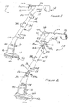
- the string trimmer 10 generally includes a handle assembly 12, an intermediate assembly or neck portion 14 and a base assembly 16.
- the handle assembly 12 is further formed in a two piece, clam shell-like construction incorporating halves 12a and 12b which, when assembled, fit together to form the handle assembly 12 and to enclose therein internal component parts standard to a conventional string trimmer.
- the base assembly 16 likewise includes halves 16a and 16b which fit together when assembled to form a rigid assembly.
- the intermediate assembly or neck portion 14 is similarly formed from two halves 14a and 14b (shown in Figure 2) which when assembled together form a rigid component.
- the handle assembly 12 includes a trigger 18 which is manually engagable with the finger of one hand, while the same hand grasps a handle portion 20.
- the trigger 18 is used to control on/off operation of a motor (not shown) enclosed within the base assembly 16 which drives a conventional cutting line rotationally relative to the base assembly 16.
- the handle assembly 12 further includes a grippable support portion 22 which may be grasped with the other hand of the individual to allow the operator to easily and conveniently manoeuvre the trimmer apparatus 10 during use.
- the intermediate assembly 14 includes a plurality of recesses 24 disposed at an upper end portion 26 thereof and a pair of recesses 28 formed in a lower end portion 30 thereof.
- a third pair of recesses 32 are formed at a centre portion 34 of the intermediate assembly 14.
- the recesses 24 and 28 accept threaded nuts which allow the two intermediate half members 14a and 14b to be secured together via a pair of bolts which extend through each intermediate half 14a and 14b once the members 14a and 14b are fitted together.
- the intermediate assembly 14 may be secured together at its centre portion 34 prior to being packaged in a shipping container and shipped for wholesale or retail sale.
- the operator does not need to assemble the intermediate assembly 14, but rather merely secure the handle assembly 12 and the base assembly 16 to the intermediate assembly 14. This feature of the present invention will be described in greater detail in the following paragraphs.
- the base assembly 16 includes an upper portion 36, a plurality of slots 38 for allowing airflow into and through the interior of the base assembly 16, a motor housing portion 40 and a uniquely shaped guard 42.
- the upper portion 36, motor housing portion 40 and guard 42 are integrally formed such that the base assembly is formed by securing the two base assembly halves 16a and 16b together via conventional threaded screws.
- the coupling assembly 44a comprises a coupling neck 46 which protrudes from a lower portion 48 of the handle assembly 20 and a coupling recess 50 which is formed at the upper end portion 26 of the intermediate assembly 14.
- the coupling assembly 44b includes a coupling neck 52 which is formed at the upper portion 36 of the base assembly 16 and a coupling recess 54 which is formed at the lower end portion 30 of the intermediate assembly 34.
- the coupling assemblies 44 and 44b are essentially identical.
- the string trimmer 10 forms an assembly having three major component sections (i.e. , handle assembly 20, intermediate assembly 34 and base assembly 16) which may be "knocked-down" prior to shipping of the string trimmer 10.
- handle assembly 20, intermediate assembly 34 and base assembly 16 three major component sections
- intermediate assembly 34 and base assembly 16 three major component sections
- This enables the string trimmer 10 to be packaged in substantially smaller and more compact shipping containers than would otherwise be required if the string trimmer 10 had to be shipped in fully assembled form.
- a tangible manufacturing cost savings is realised through the use of smaller, more compact containers and packaging materials.
- the string trimmer 10 when the string trimmer 10 is first removed from its packaging or shipping container by the user, the string trimmer 10 is in disassembled form.
- the handle assembly 20 and base portion 16 are only connected, at this point, by an electrical cable 56 which electrically couples a motor positioned within the base assembly 16 with the trigger 18 of the handle assembly 20.
- the only assembly required of the user for a newly purchased string trimmer 10 is to insert the coupling neck 46 of the handle assembly 20 into the coupling recess 50 and the coupling neck 52 of the base assembly 16 into the coupling recess 54.
- Conventional bolts and threaded fasteners are then used at recesses 24 and 28 to permanently lock the handle assembly 20 and base assembly 16 to the intermediate assembly 14. Accordingly, there are no electrical wiring steps which need to be performed by the end user during assembly of the string trimmer 10.
- the complete assembly of the string trimmer 10 comprises essentially the three above-described steps.
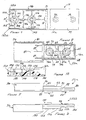
- the coupling neck 52 is formed from two mating neck halves 52a ( Figure 3) and 52b ( Figure 4).
- Neck half 52a is integrally formed with housing half 16a.
- Neck half 52b is similarly integrally formed with housing half 16b.
- the neck half 52a includes a forward boss 58 and a rearward boss 60 which are integrally formed with the neck half 52a.
- the forward and rearward bosses 58 and 60 are further structurally reinforced by support ribs 62.
- the forward boss 58 includes a pair of slots 64 formed therein, while the rearward boss 60 similarly includes a pair of slots 66 formed therein.
- Each of the slots 64 and 66 has a depth which extends down to an upper surface 62a of the ribs 62.
- the forward boss 58 includes a bevelled inner edge portion 68 and the rearward boss 60 includes a bevelled inner edge portion 70.
- the forward boss 58 further includes a bore 72 and the rearward boss 60 includes a bore 74.
- a plurality of semi-circular notches 76a, 76b and 76c are formed in general longitudinal alignment with one another to help allow the electrical cable 56 ( Figure 2) to pass through the coupling neck 52 when the latter is fully assembled.
- An upstanding shoulder portion 80 further extends about the perimeter of substantially the entire neck half 52a with the exception of a break where the semi-circular notch 76a is formed.
- a recess 82 and a plurality of support ribs 84 are also formed to help impart structural rigidity to the neck half 52a.
- the neck half 52a can be seen to include a sloped edge portion 86, a forward outer surface 88, a sloped portion 90, a rearward outer surface 92 and a protruding alignment rib 94. From Figure 5 it is also apparent that the rearward boss 60 protrudes outwardly from the upstanding shoulder portion 80 a greater degree than does the forward boss 58.
- the neck half 52b is shown.
- the neck half 52b is very similar to the neck half 52a in construction and includes a forward boss 98 and a rearward boss 100.
- the bosses 98 and 100 are structurally reinforced by reinforcing ribs 102 and 104 integrally formed with the neck half 52b.
- the forward boss 98 further includes a bore 106 and the rearward boss 100 includes a bore 108.
- the bosses 98 and 100 are further spaced apart so as to align with and be insertable partially into the bosses 58 and 60 ( Figure 3) when the two neck halves 52a and 52b are assembled together.
- the neck half 52b includes a series of semi-circular notches 110a, 110b and 110a which are in longitudinal alignment with one another.
- the notches 110a, 110b and 110c align with the notches 76a, 76b and 76c of the neck half 52a to form openings through which the electrical cable 56 extends when the two neck halves 52a and 52b are assembled together.
- the neck half 52b further includes a recess 114 and a plurality of support ribs 116 which impart structural rigidity to the neck half 52b to further resist twisting and bending forces encountered during use of the string trimmer 10.
- a groove 118 is formed about substantially the entire periphery of the neck half 52b (with the exception of the notch 110a). The groove 118 receives the protruding shoulder portion 80 of the neck half 52a therein when the two neck halves 52a and 52b are assembled together to securely interlock the two halves and even further help to impart structural rigidity to the assembled coupling neck 52.
- the neck half 52b includes a sloped edge portion 120, a forward outer surface 122, a sloped portion 124, a rearward outer surface 126, an alignment rib 128 and a wall portion 130. It can also be seen that the rearward boss 100 extends outwardly a greater distance than the forward boss 98.
- the assembled coupling neck 52 is shown.
- the forward boss 98 of neck half 52b engages within the forward boss 58 of the neck half 52a.
- the rearward boss 100 of the neck half 52b engages within the rearward boss 60 of the neck half 52a.
- the slots 64 and 66 in the bosses 58 and 60 of the neck half 52a further allow a portion of the reinforcing ribs 102 to engage therein.
- the upstanding shoulder portion 80 of the neck half 52a can also be seen engaged within the groove 118 in the neck half 52b.
- the interlocking of the support ribs 102 within the slots 64 and 66, as well as the interlocking of the upstanding shoulder portion 80 in the groove 118, further serves to "interlock" the two neck halves 52a and 52b together to form an assembly which is extremely resistant to twisting and bending forces experienced by the coupling neck 52.
- the neck half 52a includes a forward countersunk portion 132 coaxially aligned with the bore 72 and a rearward countersunk portion 134 coaxially aligned with the bore 74;.
- the neck half 52b includes a forward countersunk portion 136 coaxially aligned with the bore 106 and a rearward countersunk portion 138 coaxially aligned with the bore 108.
- the intermediate half member 14b includes a forward boss 140 and a rearward boss 142.
- the forward and rearward bosses 140 and 142, respectively, are interconnected via reinforcing ribs 144 protruding from an interior surface 145 of the member 14b.
- Reinforcing ribs 146 impart further structural rigidity to this portion of the intermediate half member 14b.
- the forward boss 140 includes a sloped portion 148, a bore 150 and a countersunk portion 152 ( Figure 10) .
- the rearward boss 142 includes a sloped wall portion 154, a bore 156 and a countersunk portion 158 ( Figure 10).
- the rearward boss 142 extends upwardly from the interior surface 145 a greater distance than does the forward boss 140. The significance of this feature will be described momentarily.
- grooves 162a and 162b extend generally longitudinally along a partial length of the intermediate half member 14b.
- the intermediate housing half member 14a includes ribs 164a and 164b which interlock with the grooves 162a and 162b, respectively, when the intermediate housing half members 14a and 14b are coupled together. This interlocking adds a further degree of resistance to twisting and bending forces which could be experienced at the coupling assemblies 44a and 44b during use of the string trimmer 10.
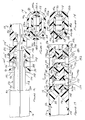
- the intermediate half member 14b includes a groove 166 which is formed in a front edge portion 168. The groove 166 allows the alignment rib 128 (shown in Figures 7, 11 and 14) of the coupling neck 52 to fit therein when the coupling neck 52 is inserted into the coupling recess 54 during assembly by the user.
- the intermediate half member 14a also includes a groove 170 formed in a front edge portion 172 so as to be positioned laterally across from the groove 166.
- the groove 170 accepts the alignment rib 94 when the assembled coupling neck 52 is inserted within the coupling recess 54.
- the grooves 170 and 166, together with the alignment ribs 94 and 128, help to "key" the coupling neck 52 to the coupling recess 54 such that the coupling neck 52 can only be inserted into the coupling recess 54 in one orientation.
- each of the coupling assemblies 44a and 44b would work equally well if only a single alignment rib is incorporated. Incorporating two alignment ribs, however, adds an even further degree of structural rigidity to each of the coupling assemblies 44a and 44b.
- the sloped portions 124 and 90 contact the sloped wall portion 148 of the forward boss 140 and the sloped wall portion 1481 of the forward boss 1401 of the intermediate half member 14a.
- the intermediate half members 14a and 14b are urged outwardly and spread apart slightly further as the coupling neck 52 is further urged into the coupling recess 54. Further insertion of the coupling neck 54 causes the forward bosses 140 and 1401 to begin riding over the rearward outer surfaces 126 and 92, respectively, as the intermediate half members 14a and 14b are caused to be gradually spread apart even further.
- the alignment ribs 94 and 128 slidably enter the grooves 170 and 166.
- the sloped wall portion 154 of the rearward boss 142 and the sloped wall portion 145' of the rearward boss 142' snappingly engage within the countersunk portions 136 and 132' respectively, of the coupling neck 52, once the coupling neck 52 is fully inserted in the coupling recess 54.
- the interlocking of the alignment ribs 94 and 128 with the grooves 170 and 166, respectively, is seen particularly well in Figure 14.
- Figure 13 shows the final steps in assembling the string trimmer.
- a threaded bolt 174 is inserted through the bore 150, the bore 108, the bore 74 and a bore 150' of the intermediate half member 14a.
- a threaded nut 174a is inserted within a first one of the recesses 28 in the intermediate half member 14a while a head portion 174b of the threaded bolt 174a is placed within a recesses 175 in the intermediate half member 14b, to threadably engage the threaded bolt 174.
- Another threaded bolt 178 is inserted through the bore 156, the bore 106, the bore 72 and a bore 156'.
- a threaded nut 178a is inserted within the other one of the recesses 28 while a head portion 178b is placed within a recess 182.
- a channel-like opening is formed by the semi-circular notches 76a and 110a, as indicated by reference numeral 180. Through this channel-like opening extends the electrical cable 56 shown in Figure 2.
- the bosses 140 and 142 could easily be formed with blind holes which accept self-tapping screws. In this manner separate threaded nuts would not be required.
- only one threaded bolt and threaded nut could be used instead of a pair as shown in Figure 13 if so desired without a significant loss of structural rigidity of the fully assembled apparatus 10.
- the base assembly 16, intermediate coupling assembly 14 and handle assembly 12 are all preferably manufactured from a suitably high-strength plastic.
- An added feature of the construction of the coupling assemblies 44a and 44b is that suitably high-strength, rigid joints can be formed from plastics which might not otherwise be suitable for this purpose.
- the string trimmer handle assembly 12, intermediate assembly 14 and base assembly 16 may all be formed from polypropylene, which is generally less rigid, but less costly, than ABS plastic, which would normally be required to provide suitable strength and rigidity for the string trimmer components. Accordingly, the construction of trimmer apparatus 10 of the present invention allows the plastic molded components of the invention to be constructed of less expensive plastics without sacrificing sturdiness, rigidity and general durability.
- the coupling necks 46 and 52 and the coupling recesses 50 and 54 of the string trimmer 10 of the present invention thus allow the trimmer 10 to be quickly and easily assembled by a person of limited mechanical understanding and without the need for specialised tools which would not normally be available or kept on hand by individuals such as homeowners.
- the string trimmer apparatus 10 of the present invention forms a rigid assembly which is highly resistant to twisting and bending forces which might be experienced during use of the trimmer apparatus.
- the alignment ribs 94 and 128 and the grooves 170 and 166 further ensure that the user does not incorrectly assemble the string trimmer apparatus 10, since the coupling necks 46 and 52 can only be inserted into their associated coupling recesses 50 and 54 in one orientation.
- teachings of the present invention could be adapted with little or no modification to virtually any hand-holdable tool or appliance.
- the teachings of the present invention are particularly applicable to any hand-holdable tool or appliance having an elongated body which requires a lengthy shipping container, or which would be more advantageously shipped in a knocked-down configuration.
Landscapes
- Life Sciences & Earth Sciences (AREA)
- Environmental Sciences (AREA)
- Engineering & Computer Science (AREA)
- Mechanical Engineering (AREA)
- Harvester Elements (AREA)
Applications Claiming Priority (4)
| Application Number | Priority Date | Filing Date | Title |
|---|---|---|---|
| US326827 | 1994-10-20 | ||
| US08/326,827 US5615970A (en) | 1994-10-20 | 1994-10-20 | String trimmer having knock-down handle |
| EP95307435A EP0707924B1 (fr) | 1994-10-20 | 1995-10-19 | Tondeuse à fil de coupe munie d'une manche rabattable |
| EP02015926A EP1249317B1 (fr) | 1994-10-20 | 1995-10-19 | Tondeuse à fil de coupe munie d'un manche rabattable |
Related Parent Applications (1)
| Application Number | Title | Priority Date | Filing Date |
|---|---|---|---|
| EP02015926A Division EP1249317B1 (fr) | 1994-10-20 | 1995-10-19 | Tondeuse à fil de coupe munie d'un manche rabattable |
Publications (3)
| Publication Number | Publication Date |
|---|---|
| EP1527672A2 true EP1527672A2 (fr) | 2005-05-04 |
| EP1527672A3 EP1527672A3 (fr) | 2005-07-27 |
| EP1527672B1 EP1527672B1 (fr) | 2007-04-11 |
Family
ID=23273880
Family Applications (3)
| Application Number | Title | Priority Date | Filing Date |
|---|---|---|---|
| EP95307435A Expired - Lifetime EP0707924B1 (fr) | 1994-10-20 | 1995-10-19 | Tondeuse à fil de coupe munie d'une manche rabattable |
| EP02015926A Expired - Lifetime EP1249317B1 (fr) | 1994-10-20 | 1995-10-19 | Tondeuse à fil de coupe munie d'un manche rabattable |
| EP05002231A Expired - Lifetime EP1527672B1 (fr) | 1994-10-20 | 1995-10-19 | Tondeuse à fil de coupe munie d'un manche rabattable |
Family Applications Before (2)
| Application Number | Title | Priority Date | Filing Date |
|---|---|---|---|
| EP95307435A Expired - Lifetime EP0707924B1 (fr) | 1994-10-20 | 1995-10-19 | Tondeuse à fil de coupe munie d'une manche rabattable |
| EP02015926A Expired - Lifetime EP1249317B1 (fr) | 1994-10-20 | 1995-10-19 | Tondeuse à fil de coupe munie d'un manche rabattable |
Country Status (5)
| Country | Link |
|---|---|
| US (1) | US5615970A (fr) |
| EP (3) | EP0707924B1 (fr) |
| CA (1) | CA2160844C (fr) |
| DE (3) | DE69530158T2 (fr) |
| MX (1) | MX9504460A (fr) |
Families Citing this family (27)
| Publication number | Priority date | Publication date | Assignee | Title |
|---|---|---|---|---|
| US6052976A (en) * | 1998-06-19 | 2000-04-25 | The Toro Company | Trimmer shield for grass trimmer |
| IT248273Y1 (it) * | 1999-08-27 | 2002-12-16 | Eurosystems S P A | Motozappa portatile. |
| DE19956332A1 (de) * | 1999-11-23 | 2001-05-31 | Stihl Maschf Andreas | Freischneider |
| USD450226S1 (en) | 2000-02-03 | 2001-11-13 | The Toro Company | Vegetation trimmer |
| EP1210858B1 (fr) | 2000-11-29 | 2006-12-20 | Black & Decker Inc. | Protecteur de plantes |
| EP1210859A1 (fr) | 2000-11-29 | 2002-06-05 | Black & Decker Inc. | Protecteur de plantes |
| USD457042S1 (en) | 2001-03-28 | 2002-05-14 | Jenn Feng Industrial Co., Ltd. | Lawn mower |
| USD456675S1 (en) | 2001-03-28 | 2002-05-07 | Jenn Feng Industrial Co., Ltd. | Lawn mower |
| USD465623S1 (en) | 2001-06-18 | 2002-11-12 | Black & Decker Inc. | Vacuum cleaner |
| US6564423B2 (en) | 2001-06-21 | 2003-05-20 | Black & Decker Inc. | Two piece upright handle assembly for a vacuum cleaner system |
| USD463081S1 (en) | 2001-07-10 | 2002-09-17 | Black & Decker Inc. | Handle for a vacuum cleaner |
| US7134208B2 (en) * | 2002-12-23 | 2006-11-14 | Black & Decker Inc. | Ergonomic handle for vegetation trimmer |
| USD513574S1 (en) | 2004-02-13 | 2006-01-17 | Fisher David B | Extended reach hedge trimmer handle |
| USD510512S1 (en) | 2004-03-24 | 2005-10-11 | Black & Decker Inc. | String trimmer |
| US7156435B1 (en) * | 2004-10-25 | 2007-01-02 | Costantinos Mourelatos | Snow shovel |
| US7963041B1 (en) | 2006-07-25 | 2011-06-21 | Smith Craig A | Guard for filament-type trimmer for protection while trimming vegetation |
| US7926141B2 (en) * | 2006-08-15 | 2011-04-19 | Umagination Labs, L.P. | Systems and methods of a gutter cleaning system |
| US7886399B2 (en) * | 2006-08-15 | 2011-02-15 | Umagination Labs, L.P. | Systems and methods for robotic gutter cleaning along an axis of rotation |
| US7979945B2 (en) * | 2006-08-15 | 2011-07-19 | Umagination Labs, L.P. | Systems and methods for robotic gutter cleaning |
| US7913345B2 (en) | 2006-08-15 | 2011-03-29 | Umagination Labs, L.P. | Systems and methods of a power tool system with interchangeable functional attachments |
| US7743683B2 (en) * | 2006-08-15 | 2010-06-29 | Umagination Labs, L.P. | Systems and methods of a power tool system with interchangeable functional attachments powered by a direct rotational drive |
| USD566491S1 (en) | 2006-12-26 | 2008-04-15 | The Toro Company | Vegetation trimmer |
| EP2545759B1 (fr) * | 2011-07-14 | 2014-10-08 | Black & Decker Inc. | Dispositif électrique |
| EP2770814B1 (fr) | 2011-10-27 | 2020-02-19 | Husqvarna AB | Outil électrique portatif alimenté par batterie |
| US20200245549A1 (en) * | 2017-10-24 | 2020-08-06 | Suzhou Cleva Precision Machinery & Technology Co., Ltd. | Gardening Tool |
| EP3811758B1 (fr) * | 2019-10-22 | 2023-08-02 | Andreas Stihl AG & Co. KG | Appareil de traitement manuel pourvu de raccord électrique |
| EP3922414B1 (fr) * | 2020-06-09 | 2025-08-27 | Andreas Stihl AG & Co. KG | Boitier |
Family Cites Families (39)
| Publication number | Priority date | Publication date | Assignee | Title |
|---|---|---|---|---|
| US367578A (en) * | 1887-04-04 | 1887-08-02 | Hose and pipe coupling | |
| US1867226A (en) * | 1929-07-16 | 1932-07-12 | Martin James | Frame-like structure for vehicles, aircraft, and other conveyers |
| US2230703A (en) * | 1934-02-17 | 1941-02-04 | Hoover Co | Suction cleaner |
| US2511160A (en) * | 1946-07-01 | 1950-06-13 | E T Rugg Company | Knockdown type lawn mower handle assembly |
| US2950134A (en) * | 1957-02-13 | 1960-08-23 | Tinnerman Products Inc | Fastening assembly and clip |
| US3484736A (en) * | 1967-01-20 | 1969-12-16 | David S Wyse | Quick disconnector |
| US3549189A (en) * | 1968-08-09 | 1970-12-22 | Michael Alosi | Tool handle |
| US3569903A (en) * | 1969-08-07 | 1971-03-09 | Sealectro Corp | Coaxial connector with axial interlock |
| US3858383A (en) * | 1971-04-05 | 1975-01-07 | Rockwell International Corp | Electrically powered tool |
| US4052789A (en) * | 1976-12-02 | 1977-10-11 | Weed Eater, Inc. | Rotary cutting assembly |
| US3759020A (en) * | 1972-07-31 | 1973-09-18 | Burgess Vibrocrafters | Grass clipper |
| US3803819A (en) * | 1972-11-28 | 1974-04-16 | Black & Decker Mfg Co | Trimmer-edger with handle clamp |
| US3886716A (en) * | 1973-02-26 | 1975-06-03 | Rockwell International Corp | Electrically powered grass trimmer |
| US3879573A (en) * | 1973-12-05 | 1975-04-22 | Black & Decker Mfg Co | Electrical device handle and protector therefor |
| GB1454223A (en) * | 1974-11-14 | 1976-11-03 | Kendrick Sinonsen T | Tools for gardening farming roadworking and the like |
| US4018037A (en) * | 1975-08-25 | 1977-04-19 | The Black And Decker Manufacturing Company | Attaching means for converting a conventional hand-held portable power tool or appliance for stand-up usage |
| US4211004A (en) * | 1975-10-22 | 1980-07-08 | Emerson Electric Co. | String-type weed cutter with mechanical line feed |
| US4089114A (en) * | 1976-08-31 | 1978-05-16 | Disston, Inc. | Cutting device |
| US4156967A (en) * | 1976-12-02 | 1979-06-05 | Weed Eater, Inc. | Rotary cutting assembly |
| US4136446A (en) * | 1977-01-24 | 1979-01-30 | Weed Eater, Inc. | Rotary cutting assembly with mechanical line feed |
| US4852258A (en) * | 1981-03-19 | 1989-08-01 | White Consolidated Industries, Inc. | Apparatus for cutting vegetation |
| US4364435A (en) * | 1980-12-22 | 1982-12-21 | Emerson Electric Co. | Lawn edger |
| US4391545A (en) * | 1980-01-31 | 1983-07-05 | Metaport Corporation | Releasable locking connector |
| DE8012962U1 (de) * | 1980-05-13 | 1980-08-14 | Max Langenstein, Feld- Und Gartengeraete Gmbh & Co, 7918 Illertissen | Rasenkantenschneider |
| US4397088A (en) * | 1981-02-09 | 1983-08-09 | The Toro Company | Power equipment unit with split handle |
| US4505040A (en) * | 1982-08-31 | 1985-03-19 | Everts Robert G | Coupling for interconnecting two handle portions of a power driven implement |
| US4567657A (en) * | 1983-10-05 | 1986-02-04 | Textron Inc. | String trimmer tube clamping |
| US4516289A (en) * | 1984-04-30 | 1985-05-14 | The Singer Company | Handle construction for floor care appliance |
| DE8623173U1 (de) * | 1986-08-29 | 1987-01-08 | Fa. Andreas Stihl, 7050 Waiblingen | Freischneidegerät |
| US4860451A (en) * | 1986-11-28 | 1989-08-29 | Allegretti & Company | String trimmer |
| US4819742A (en) * | 1987-06-12 | 1989-04-11 | White Consolidated Industries, Inc. | Vibration-damping control handle for a portable power tool |
| US4829675A (en) * | 1987-08-19 | 1989-05-16 | The Toro Company | Electrical appliance and handle for same |
| US4791826A (en) * | 1987-11-19 | 1988-12-20 | Chrysler Motors Corporation | Gearshift knob joining arrangement |
| US4904827A (en) * | 1989-01-30 | 1990-02-27 | Harold Joseph Coleman | Electric cord-protecting shipping plug |
| US4976031A (en) * | 1989-06-01 | 1990-12-11 | Ron Miller | Telescopic hedge trimming apparatus |
| DK52990D0 (da) * | 1990-03-01 | 1990-03-01 | Fiskars Zinck Lysbro As | Koblingsbeslag til et have- eller gartnerredskab |
| USD351768S (en) | 1992-04-24 | 1994-10-25 | Mcculloch Corporation | Electric grass trimmer |
| US5379846A (en) * | 1993-01-07 | 1995-01-10 | Black & Decker Inc. | Electrical appliance and handle for same |
| US5446964A (en) * | 1993-07-22 | 1995-09-05 | Wci Outdoor Products, Inc. | Apparatus and method for packaging and assembling a flexible line trimmer |
-
1994
- 1994-10-20 US US08/326,827 patent/US5615970A/en not_active Expired - Lifetime
-
1995
- 1995-10-18 CA CA002160844A patent/CA2160844C/fr not_active Expired - Fee Related
- 1995-10-19 DE DE69530158T patent/DE69530158T2/de not_active Expired - Lifetime
- 1995-10-19 DE DE69535464T patent/DE69535464T2/de not_active Expired - Lifetime
- 1995-10-19 EP EP95307435A patent/EP0707924B1/fr not_active Expired - Lifetime
- 1995-10-19 EP EP02015926A patent/EP1249317B1/fr not_active Expired - Lifetime
- 1995-10-19 DE DE69534168T patent/DE69534168T2/de not_active Expired - Lifetime
- 1995-10-19 EP EP05002231A patent/EP1527672B1/fr not_active Expired - Lifetime
- 1995-10-20 MX MX9504460A patent/MX9504460A/es unknown
Also Published As
| Publication number | Publication date |
|---|---|
| EP1249317A3 (fr) | 2003-03-05 |
| DE69534168T2 (de) | 2006-03-09 |
| EP1249317B1 (fr) | 2005-04-20 |
| EP0707924B1 (fr) | 2003-04-02 |
| DE69530158D1 (de) | 2003-05-08 |
| DE69534168D1 (de) | 2005-05-25 |
| EP0707924A3 (fr) | 1997-06-11 |
| CA2160844A1 (fr) | 1996-04-21 |
| DE69535464D1 (de) | 2007-05-24 |
| EP0707924A2 (fr) | 1996-04-24 |
| DE69530158T2 (de) | 2003-10-09 |
| EP1249317A2 (fr) | 2002-10-16 |
| DE69535464T2 (de) | 2008-01-03 |
| CA2160844C (fr) | 2003-12-30 |
| EP1527672B1 (fr) | 2007-04-11 |
| US5615970A (en) | 1997-04-01 |
| EP1527672A3 (fr) | 2005-07-27 |
| MX9504460A (es) | 1997-01-31 |
Similar Documents
| Publication | Publication Date | Title |
|---|---|---|
| EP1527672B1 (fr) | Tondeuse à fil de coupe munie d'un manche rabattable | |
| US5594990A (en) | Lawn trimming and edging apparatus having motor housing rotatable on extendable handle | |
| EP0195146B1 (fr) | Accouplement pour la connexion de deux poignées d'un appareil motorisé | |
| US6052976A (en) | Trimmer shield for grass trimmer | |
| US4638562A (en) | Extension handles for hedge trimmers | |
| US20080141541A1 (en) | Power tool for completing yard work and process for making same | |
| EP1020257B1 (fr) | Manche de tondeuse | |
| USD349220S (en) | Electric grass trimmer and edger | |
| US5070576A (en) | Hedge trimmer extension handle apparatus | |
| CA1217902A (fr) | Porte-outil pour materiel mecanique | |
| US11780073B2 (en) | Handle with offset connector | |
| US4371079A (en) | Container for chain saws | |
| US3843224A (en) | Detachable cord set for electric device | |
| US6434834B2 (en) | Lopping apparatus having stowable blades and associated method | |
| JPH07308113A (ja) | 可とう性ライントリマーを梱包し、組み立てる装置および方法 | |
| US6484484B1 (en) | Lawn mower for providing power to a garden implement | |
| US5379846A (en) | Electrical appliance and handle for same | |
| CN112335437A (zh) | 一种手柄可更换的多功能园林修整工具 | |
| EP3809814B1 (fr) | Outil de récolte de fruits | |
| CA2160843A1 (fr) | Lame coupe-fil pour minitondeuse a fil rotatif | |
| JPH0411487Y2 (fr) | ||
| US20240286267A1 (en) | Two Piece Camp Axe | |
| JP2562751Y2 (ja) | 補助ハンドルを備えた刈込機 | |
| HK1057722A (en) | Collapsable transverse handle for elongated tool | |
| EP2839728A1 (fr) | Véhicule, tel qu'un équipement de jardinage à roues |
Legal Events
| Date | Code | Title | Description |
|---|---|---|---|
| PUAI | Public reference made under article 153(3) epc to a published international application that has entered the european phase |
Free format text: ORIGINAL CODE: 0009012 |
|
| 17P | Request for examination filed |
Effective date: 20050203 |
|
| AC | Divisional application: reference to earlier application |
Ref document number: 1249317 Country of ref document: EP Kind code of ref document: P Ref document number: 0707924 Country of ref document: EP Kind code of ref document: P |
|
| AK | Designated contracting states |
Kind code of ref document: A2 Designated state(s): CH DE FR GB IT LI |
|
| PUAL | Search report despatched |
Free format text: ORIGINAL CODE: 0009013 |
|
| AK | Designated contracting states |
Kind code of ref document: A3 Designated state(s): CH DE FR GB IT LI |
|
| RIC1 | Information provided on ipc code assigned before grant |
Ipc: 7B 25F 5/02 B Ipc: 7B 25G 3/12 A Ipc: 7A 01D 34/00 B Ipc: 7B 25G 3/18 B |
|
| AKX | Designation fees paid |
Designated state(s): CH DE FR GB IT LI |
|
| GRAP | Despatch of communication of intention to grant a patent |
Free format text: ORIGINAL CODE: EPIDOSNIGR1 |
|
| GRAS | Grant fee paid |
Free format text: ORIGINAL CODE: EPIDOSNIGR3 |
|
| GRAA | (expected) grant |
Free format text: ORIGINAL CODE: 0009210 |
|
| AC | Divisional application: reference to earlier application |
Ref document number: 1249317 Country of ref document: EP Kind code of ref document: P Ref document number: 0707924 Country of ref document: EP Kind code of ref document: P |
|
| AK | Designated contracting states |
Kind code of ref document: B1 Designated state(s): CH DE FR GB IT LI |
|
| REG | Reference to a national code |
Ref country code: GB Ref legal event code: FG4D |
|
| REG | Reference to a national code |
Ref country code: CH Ref legal event code: EP |
|
| REF | Corresponds to: |
Ref document number: 69535464 Country of ref document: DE Date of ref document: 20070524 Kind code of ref document: P |
|
| REG | Reference to a national code |
Ref country code: CH Ref legal event code: NV Representative=s name: E. BLUM & CO. AG PATENT- UND MARKENANWAELTE VSP |
|
| ET | Fr: translation filed | ||
| PLBE | No opposition filed within time limit |
Free format text: ORIGINAL CODE: 0009261 |
|
| STAA | Information on the status of an ep patent application or granted ep patent |
Free format text: STATUS: NO OPPOSITION FILED WITHIN TIME LIMIT |
|
| 26N | No opposition filed |
Effective date: 20080114 |
|
| PGFP | Annual fee paid to national office [announced via postgrant information from national office to epo] |
Ref country code: CH Payment date: 20081027 Year of fee payment: 14 |
|
| REG | Reference to a national code |
Ref country code: CH Ref legal event code: PL |
|
| PG25 | Lapsed in a contracting state [announced via postgrant information from national office to epo] |
Ref country code: CH Free format text: LAPSE BECAUSE OF NON-PAYMENT OF DUE FEES Effective date: 20091031 Ref country code: LI Free format text: LAPSE BECAUSE OF NON-PAYMENT OF DUE FEES Effective date: 20091031 |
|
| PGFP | Annual fee paid to national office [announced via postgrant information from national office to epo] |
Ref country code: DE Payment date: 20101027 Year of fee payment: 16 |
|
| PGFP | Annual fee paid to national office [announced via postgrant information from national office to epo] |
Ref country code: IT Payment date: 20101028 Year of fee payment: 16 Ref country code: GB Payment date: 20101025 Year of fee payment: 16 |
|
| PGFP | Annual fee paid to national office [announced via postgrant information from national office to epo] |
Ref country code: FR Payment date: 20111028 Year of fee payment: 17 |
|
| GBPC | Gb: european patent ceased through non-payment of renewal fee |
Effective date: 20121019 |
|
| REG | Reference to a national code |
Ref country code: FR Ref legal event code: ST Effective date: 20130628 |
|
| PG25 | Lapsed in a contracting state [announced via postgrant information from national office to epo] |
Ref country code: DE Free format text: LAPSE BECAUSE OF NON-PAYMENT OF DUE FEES Effective date: 20130501 Ref country code: GB Free format text: LAPSE BECAUSE OF NON-PAYMENT OF DUE FEES Effective date: 20121019 |
|
| REG | Reference to a national code |
Ref country code: DE Ref legal event code: R119 Ref document number: 69535464 Country of ref document: DE Effective date: 20130501 |
|
| PG25 | Lapsed in a contracting state [announced via postgrant information from national office to epo] |
Ref country code: IT Free format text: LAPSE BECAUSE OF NON-PAYMENT OF DUE FEES Effective date: 20121019 Ref country code: FR Free format text: LAPSE BECAUSE OF NON-PAYMENT OF DUE FEES Effective date: 20121031 |