EP1526979B1 - Dispositif electronique de commande et de reglage - Google Patents
Dispositif electronique de commande et de reglage Download PDFInfo
- Publication number
- EP1526979B1 EP1526979B1 EP03766059A EP03766059A EP1526979B1 EP 1526979 B1 EP1526979 B1 EP 1526979B1 EP 03766059 A EP03766059 A EP 03766059A EP 03766059 A EP03766059 A EP 03766059A EP 1526979 B1 EP1526979 B1 EP 1526979B1
- Authority
- EP
- European Patent Office
- Prior art keywords
- switching element
- electronic control
- regulating system
- eddy current
- switched
- Prior art date
- Legal status (The legal status is an assumption and is not a legal conclusion. Google has not performed a legal analysis and makes no representation as to the accuracy of the status listed.)
- Expired - Lifetime
Links
- 230000001105 regulatory effect Effects 0.000 claims description 45
- 238000012544 monitoring process Methods 0.000 claims description 7
- 230000002457 bidirectional effect Effects 0.000 claims description 5
- 230000007257 malfunction Effects 0.000 claims description 5
- 230000001276 controlling effect Effects 0.000 claims description 4
- 230000006378 damage Effects 0.000 claims description 3
- 239000004065 semiconductor Substances 0.000 claims description 3
- 230000007547 defect Effects 0.000 claims description 2
- 238000000034 method Methods 0.000 claims 4
- 230000005284 excitation Effects 0.000 abstract description 13
- 230000006870 function Effects 0.000 description 6
- 230000004913 activation Effects 0.000 description 2
- 230000005540 biological transmission Effects 0.000 description 2
- 230000008859 change Effects 0.000 description 2
- 230000007704 transition Effects 0.000 description 2
- 230000009471 action Effects 0.000 description 1
- 230000003213 activating effect Effects 0.000 description 1
- 239000000956 alloy Substances 0.000 description 1
- 229910045601 alloy Inorganic materials 0.000 description 1
- 238000005275 alloying Methods 0.000 description 1
- 238000007664 blowing Methods 0.000 description 1
- 230000009849 deactivation Effects 0.000 description 1
- 238000001514 detection method Methods 0.000 description 1
- 230000003993 interaction Effects 0.000 description 1
- 230000009467 reduction Effects 0.000 description 1
Images


Classifications
-
- B—PERFORMING OPERATIONS; TRANSPORTING
- B60—VEHICLES IN GENERAL
- B60L—PROPULSION OF ELECTRICALLY-PROPELLED VEHICLES; SUPPLYING ELECTRIC POWER FOR AUXILIARY EQUIPMENT OF ELECTRICALLY-PROPELLED VEHICLES; ELECTRODYNAMIC BRAKE SYSTEMS FOR VEHICLES IN GENERAL; MAGNETIC SUSPENSION OR LEVITATION FOR VEHICLES; MONITORING OPERATING VARIABLES OF ELECTRICALLY-PROPELLED VEHICLES; ELECTRIC SAFETY DEVICES FOR ELECTRICALLY-PROPELLED VEHICLES
- B60L7/00—Electrodynamic brake systems for vehicles in general
- B60L7/28—Eddy-current braking
-
- H—ELECTRICITY
- H02—GENERATION; CONVERSION OR DISTRIBUTION OF ELECTRIC POWER
- H02P—CONTROL OR REGULATION OF ELECTRIC MOTORS, ELECTRIC GENERATORS OR DYNAMO-ELECTRIC CONVERTERS; CONTROLLING TRANSFORMERS, REACTORS OR CHOKE COILS
- H02P15/00—Arrangements for controlling dynamo-electric brakes or clutches
-
- Y—GENERAL TAGGING OF NEW TECHNOLOGICAL DEVELOPMENTS; GENERAL TAGGING OF CROSS-SECTIONAL TECHNOLOGIES SPANNING OVER SEVERAL SECTIONS OF THE IPC; TECHNICAL SUBJECTS COVERED BY FORMER USPC CROSS-REFERENCE ART COLLECTIONS [XRACs] AND DIGESTS
- Y02—TECHNOLOGIES OR APPLICATIONS FOR MITIGATION OR ADAPTATION AGAINST CLIMATE CHANGE
- Y02T—CLIMATE CHANGE MITIGATION TECHNOLOGIES RELATED TO TRANSPORTATION
- Y02T10/00—Road transport of goods or passengers
- Y02T10/60—Other road transportation technologies with climate change mitigation effect
- Y02T10/64—Electric machine technologies in electromobility
Definitions
- the present invention relates to a control electronics, in particular for an eddy current brake of a vehicle, with a control or regulating device for controlling or regulating the device to be switched, preferably the excitation coils of an eddy current brake, and with a first by the control or Control device switchable switching element, which is connected in series with the device to be switched, in particular with the excitation coils of an eddy current brake.
- Eddy current brakes in vehicles are mainly used to relieve the actual main brake system of the vehicle and thus constitute additional brake devices.
- the off state is the safe operating state of such an additional brake device since a functioning brake system is already available with the main brake device.
- the problem with such devices that the malfunction of a switching element can prevent the deactivation of the device and thus the transition to the safe operating condition.
- the use of semiconductor switching elements, such as MOSFETs desirable. In these switching elements, it can lead to the so-called alloying of the transistor, after which this can no longer be switched off current-impermeable. If an all-alloy transistor is connected in series with a device to be switched and a voltage source, the circuit closed by the transistor and thus the operation of the device can no longer be interrupted.
- the object of the invention is to achieve an increase in reliability in generic devices according to the preamble of claim 1.
- An advantageous embodiment of the invention results from the fact that with at least one, preferably each of parallel to the device to be switched, preferably connected to the exciting coils of an eddy current switching elements each electrical resistance is connected in series, each of the electrical resistors in parallel to the switching device, preferably the exciting coils of an eddy current brake, is switched.
- These resistors limit the current flowing through a single switching element current and thus the load of this switching element, while the first switching element connected in series with all these switching elements the total current than Sum of the flows through the individual switching elements streams results, is exposed. Thus, the probability that it comes to a burn through of the first switching element, again increased.
- At least one switching element comprises a semiconductor component as a switch, preferably a MOSFET.
- Such switching elements are commercially available at low cost and switchable with low operating voltages.
- a further advantageous embodiment of the invention results from the fact that the control or regulating device can be supplied with a signal which is characteristic of the operating state of at least one switching element.
- the current state of the individual switching elements can be assessed at any time. For example, the voltage drop occurring along a switching element connected in series with the switching device to be switched can be deduced, given a known resistance, from the current flowing through the device to be switched. It is also advisable to provide a temperature sensor for monitoring the operating temperature of the device to be switched, whose signal can be fed to at least the control or regulating device. If a certain, predetermined maximum temperature is exceeded, the output of a temperature warning and, if appropriate, the shutdown of the device to be switched can be provided. Analogously, a voltage sensor can monitor the electrical operating voltage of the device to be switched and / or the control or regulating electronics and, if appropriate, emit an alarm or reduce the braking power (current consumption).
- a further advantageous embodiment of the invention results from the fact that the device to be switched comprises excitation coils of an eddy current brake which can be switched to control the braking power as a whole with a pulse width modulated (PWM) DC voltage by the switching element connected in series with the exciter coils.
- PWM pulse width modulated
- the operation of such devices by the application of a pulse-width modulated DC voltage to the switched in series with the excitation coil switching element is already known and therefore will not be described here. It should be mentioned that this change in current leads to disturbing voltage fluctuations in the electrical system of the vehicle. The magnitude of the voltage fluctuation is linear with the rate of current change and becomes problematic especially at high switching frequencies.
- the on or off edges of the pulse-width-modulated signal are flattened, which leads to a reduction of the voltage fluctuations.
- the current rises from zero to the desired maximum value, for example over a period of about 100 microseconds, and after a certain time in a controlled manner also falls back to zero within 100 microseconds from this maximum value.
- This switching signal can be compared with the control signal supplied to the current signal actually flowing through the circuit. This allows a readjustment of the applied switching signal.
- This allows optimal interaction with other electronic devices arranged in the vehicle, which further increases the operational safety of the device. For example, upon activation of the anti-lock brake system of the vehicle, a simultaneous startup of the eddy current brake can be prevented.
- a cruise control function can be realized by the eddy current brake in a manner known per se. Furthermore, it can be provided to regulate the power of the eddy current brake via a manually operable multi-stage shift lever.
- control electronics from two spatially separate modules, such as an electronic control module (Electronic Control Module, ECM) and an electronic power supply module (Electronic Power Module, EPM) consists.
- ECM Electronic Control Module
- EPM Electronic Power Module
- the ECM may be located in the vicinity of the other on-board systems, for example in the cab of the vehicle, while the EPM is disposed on the eddy current brake itself.
- the ECM communicates with the other on-board systems and evaluates the ABS, speedometer signal and position of the control lever to determine the required braking power.
- the EPM implements the specifications of the ECM and controls the eddy-current brake with pulse width modulation. Via a CAN (Controller Area Network) bus connection with a corresponding protocol connection, the entire system can be controlled and controlled via an in-vehicle CAN bus.
- CAN Controller Area Network
- the control electronics when a malfunction of one of its components and / or the device to be switched occurs, the control electronics enters an error operating mode. In this mode, the presence of the malfunction is constantly checked, allowing a transition to the normal operating mode after the malfunction disappears. If the control electronics determines the destruction of one of the switching elements, it advantageously comes to shutdown of the device, the re-commissioning is prevented by the control or control electronics.
- Fig. 1 shows a control electronics with a control or regulating device 1, which is connected via lines 9, 10 with other components not shown in connection and via lines 4, 6 switching elements 3, 5 can turn on.
- the first switching element 3 is connected in series with the excitation coil 2 of an eddy current brake, not shown.
- the actuating signal of the control or regulating device 1 via the line 4 can be formed according to the invention pulse width modulated.
- the control or regulating device 1 via the line 6, the second switching element 5 turn on. Due to the lower resistance of the two series-connected switching elements 3, 5 in comparison to the much larger resistance of the leading via the excitation coil 2 and switching element 3 current path, there is a large short-circuit current through the second switching element 5 and the first switching element 3 and thus for blowing through the already in normal operation thermally loaded first switching element 3. As a result, the conductive connection between the battery 7 and the mass 8 is interrupted, whereby the eddy current brake goes into the off state.
- a battery for example, a 12-volt or a 24-volt battery may be provided.
- the internal resistance of the excitation coils 2 is for example between 120 milliohms and 170 milliohms.
- the current occurring in normal operation ranges between 70 amps and 200 amps.
- the internal resistance of a transistor connected in the direction of conduction for example, is in the range of a few milliohms. From this it can be estimated that the occurring short-circuit current is about 1-2 orders of magnitude larger than the normal operating current.
- the burning of the switching elements usually takes place already at about ten times the rated current.
- Fig. 2 shows a variant of the embodiment according to Fig. 1 in which a plurality of second switching elements 5 are connected in parallel with the device to be switched here the excitation coils 2 of an eddy current brake and in series with the first switching element 3.
- each second switching element 5 is connected in series with a resistor 11, which limits the current flow through the individual second switching elements 5.
- the current flowing through the first switching element 3 is given by the sum of the individual partial currents in the branches of the parallel circuit.
- Fig. 3 schematically shows the structure of the electronic power supply module EPM a two-piece control electronics.
- the EPM Via a bidirectional interface 13, the EPM is supplied with data and / or energy by lines 14 from the ECM, not shown, and in turn can transmit data to the ECM.
- the electrical circuit 19 has a battery 7 and a ground 8 and interposed switching modules 12,12 'and excitation coils 2.
- the switching modules 12,12 ' have on the one hand switching elements 3.5 for interrupting or closing the electric circuit 19 and on the other hand additional, corresponding to the prior art, and therefore not shown circuits for controlling the operating state of the individual switching modules 12,12'sowie to protect the actual switching elements 3.5.
- the control or regulating device 1 comprises an overvoltage protection 17, an overtemperature warning device 18, a power controller 15, an error unit 16 and a function monitoring unit 20.
- the power controller 15 receives via line 23, interface 13 and line 14 the pulse width modulated actuation signal 38 generated by the ECM not shown here and processed by the interface 13.
- the flank flattening is performed in the power controller 15 itself and the actuation signal 34 modified in this way via the line 24 delivered.
- the error unit 16 monitors the operating state of the EPM and outputs a release signal in the normal operating state via line 25. Only when this enable signal on line 25 and at the same time the actuation signal of the power controller 15 on line 24, it comes to the Leitendsciens the first switching module 12.
- the actuation signal 34 of the power controller 15 is pulsed . If an overvoltage is detected by the overvoltage protection unit 17 in a manner not shown, it may also come to Leitendcharge the first switching module 12 via the line 26 to prevent destruction of the sensitive switching elements of the circuit 19. This Leitendbib takes place only as long as there is an overvoltage.
- the first - connected in series with the device to be switched - switching module 12 is therefore only turned on when simultaneously via line 24 an actuating signal of the power controller 15 and via line 25 an enable signal of the error unit 16 or in the presence of an overvoltage signal of the overvoltage protection unit 17 on line 26.
- the second switching module 12 ' which is connected in parallel to the exciter coils 2 and in series with the first switching module 12', and as described above acts as a switchable short-circuit fuse, via the error unit 16 and line 28 or via the overvoltage protection unit 17 on line 27th be turned on.
- the first switching module 12 provides via line 29 information about its operating state to the power controller 15 and via line 30 to the function monitoring unit 20.
- the function monitoring unit 20 is via line 32 signals to the error unit 16 and via line 33 to the overvoltage protection unit 17 on. These signals are used for example for overcurrent or short-circuit detection, for under- or overvoltage monitoring for overtemperature shutdown, for example, at 105 degrees Celsius and to make a switch-on to prevent the commissioning of the eddy current brake.
- the error unit 16 is via line 22 interface 13 and Line 14 forwards information to the ECM and receives information from the ECM via line 14 interface 13 and line 21. As a result, it is possible, for example, to read out the error memory of the error unit 16 and if necessary to delete it again.
- the forwarding of information via the lines 14 takes place for example via a galvanically isolated short-circuit-proof alternating voltage in a frequency range of 60 to 200 kilohertz.
- the different frequencies have different functions. For example, at a rate of 60 kilohertz, EPM activation may occur through the ECM without, however, activating the eddy current brake itself.
- the commissioning of the eddy current brake can be carried out at a frequency between 100 and 140 kilohertz, wherein the pulse width modulation can be generated by switching the frequency between 80 and 120 kilohertz.
- the resetting of the error detected by the error unit 16 in the EPM can for example take place at a frequency of 200 kilohertz. Due to the load on the two-wire interface with defined ohmic loads, various errors can be reported back to the ECM. The regulation of the EPM by the ECM can be made depending on this information.
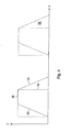
- Fig. 4 shows the pulse width modulated actuation signal 34 as a function of the time t, wherein the current I is plotted on the ordinate.
- the flattened switch-on edges 35 and switch-off edges 37 as well as the maximum value 36 can be seen.
- Plotted in dashed lines is a pulse-width-modulated actuation signal 38 without flattened flanks according to the prior art.
Landscapes
- Engineering & Computer Science (AREA)
- Power Engineering (AREA)
- Transportation (AREA)
- Mechanical Engineering (AREA)
- Regulating Braking Force (AREA)
- Valves And Accessory Devices For Braking Systems (AREA)
Abstract
Claims (18)
- Dispositif électronique de commande ou de réglage, en particulier pour un frein à courants de Foucault d'un véhicule, équipé d'une unité de commande ou de réglage destinée à commander ou régler le dispositif à commander, de préférence des bobines d'excitation d'un frein à courants de Foucault, et d'un premier élément de commutation pouvant être commandé par l'unité de commande ou de réglage qui est monté en série avec le dispositif à commander, en particulier avec les bobines d'excitation d'un frein à courants de Foucault, caractérisé en ce que, pour augmenter la sécurité de fonctionnement, au moins un autre élément de commutation (5) pouvant être commandé par l'unité de commande ou de réglage est monté en parallèle au dispositif à commander, de préférence en parallèle avec les bobines d'excitation (2) d'un frein à courants de Foucault, et en série avec le premier élément de commutation (3), dans lequel en cas de défaillance du premier élément de commutation (3) empêchant une rupture du circuit électrique fermé par le premier élément de commutation (3) par le biais du premier élément de commutation (3), le au moins un autre élément de commutation (5) peut être commandé pour être conducteur afin d'obtenir un claquage du premier élément de commutation (3) et ainsi l'interruption du circuit électrique par l'unité de commande ou de réglage.
- Dispositif électronique de commande ou de réglage selon la revendication 1, caractérisé en ce que tous les éléments de commutation (3, 5) sont identiques.
- Dispositif électronique de commande ou de réglage selon la revendication 1 ou 2, caractérisé en ce qu'une résistance électrique (11) est montée en série avec au moins un élément de commutation (5), de préférence avec chacun des éléments de commutation (5) montés en parallèle au dispositif à commander, de préférence aux bobines d'excitation (2) d'un frein à courants de Foucault, dans lequel chacune des résistances électriques (11) est montée en parallèle au dispositif à commander, de préférence aux bobines d'excitation (2) d'un frein à courants de Foucault.
- Dispositif électronique de commande ou de réglage selon la revendication 2, caractérisé en ce que toutes les résistances (11) ont la même valeur ohmique.
- Dispositif électronique de commande ou de réglage selon l'une des revendications 1 à 4, caractérisé en ce qu'au moins un élément de commutation comporte un élément semi-conducteur servant de commutateur, de préférence un transistor MOSFET.
- Dispositif électronique de commande ou de réglage selon l'une des revendications 1 à 5, caractérisé en ce qu'un signal caractéristique pour l'état de fonctionnement d'au moins un élément de commutation (3, 5, 12) peut être amené à l'unité de commande ou de réglage (1).
- Dispositif électronique de commande ou de réglage selon la revendication 6, caractérisé en ce que le signal contient des informations sur la chute de tension aux bornes de l'élément de commutation respectif (3, 5, 12).
- Dispositif électronique de commande ou de réglage selon l'une des revendications 1 à 7, caractérisé en ce qu'il comporte un capteur de température pour surveiller la température de fonctionnement du dispositif électronique de commande ou de réglage même et/ou du dispositif à commander, de préférence du frein à courants de Foucault, et dont le signal peut être amené au moins à l'unité de commande ou de réglage (1).
- Dispositif électronique de commande ou de réglage selon l'une des revendications 1 à 8, caractérisé en ce qu'il comporte un capteur de tension pour surveiller la tension électrique de fonctionnement du dispositif à commander, de préférence des bobines d'excitation (2) d'un frein à courants de Foucault, et/ou du dispositif électronique de commande ou de réglage même, et dont le signal peut être amené au moins à l'unité de commande ou de réglage (1).
- Dispositif électronique de commande ou de réglage selon l'une des revendications 1 à 9, caractérisé en ce que le dispositif à commander comporte des bobines d'excitation (2) d'un frein à courants de Foucault qui peuvent être commandées pour régler la puissance de freinage de préférence en tant qu'ensemble avec une tension continue soumise à une modulation d'impulsions en durée par le biais de l'élément de commutation (3) monté en série avec les bobines d'excitation (2).
- Dispositif électronique de commande ou de réglage selon la revendication 10, caractérisé en ce que les fronts de commande montants (35) et/ou descendants (37) des signaux de commande (34) amenés par l'unité de commande ou de réglage (1) à l'élément de commutation (3) monté en série avec les bobines d'excitation (2) afin de minimiser des fluctuations de tension non souhaitées sont formés pour monter respectivement, descendre durant un intervalle de temps déterminé, de préférence de 100 µs environ.
- Dispositif électronique de commande ou de réglage selon l'une des revendications 1 à 11, caractérisé en ce qu'il est disposé dans un véhicule et qu'il comporte une interface (13) pour la transmission de données bidirectionnelle avec d'autres dispositifs disposés dans le véhicule - de préférence système de freinage antiblocage, compteur de vitesse, ordinateur de bord ou des dispositifs similaires.
- Dispositif électronique de commande ou de réglage selon l'une des revendications 1 à 12, caractérisé en ce qu'il est disposé dans un véhicule et se compose de deux modules disposés en des endroits différents qui sont reliées entre eux par le biais d'une interface bidirectionnelle (13) à des fins de transmission d'énergie et/ou de données, de préférence une interface à deux fils, dans lequel de préférence l'un des deux modules est disposé à proximité immédiate du frein à courants de Foucault du véhicule et de préférence l'autre des deux modules est disposé dans la cabine du conducteur du véhicule.
- Véhicule équipé d'un frein à courants de Foucault, caractérisé par un dispositif électronique de commande ou de réglage selon l'une des revendications 1 à 13.
- Procédé de commande d'un dispositif, en particulier du frein à courants de Foucault d'un véhicule, équipé d'un dispositif électronique de commande ou de réglage selon l'une des revendications 1 à 14, caractérisé en ce que, en présence d'un dysfonctionnement de l'élément de commutation (3) monté en série avec le dispositif à commander, de préférence avec des bobines d'excitation (2) d'un frein à courants de Foucault, l'arrêt du dispositif a lieu par la commande rendant conducteurs le ou les éléments de commutation (5) montés en parallèle avec le dispositif à commander et en série avec le premier élément de commutation (3).
- Procédé selon la revendication 15, caractérisé en ce que le fonctionnement de tous les éléments de commutation (3, 5, 12) est surveillé en permanence par le dispositif électronique de commande ou de réglage, de préférence par l'unité de commande et de réglage (1) et en ce que l'arrêt du dispositif a lieu en cas d'apparition d'un dysfonctionnement d'un élément de commutation (3, 5, 12).
- Procédé selon la revendication 15 ou 16, caractérisé en ce que, en cas d'apparition d'un dysfonctionnement d'un de ses composants et/ou du dispositif à commander, le dispositif électronique de commande ou de réglage passe dans un mode de fonctionnement d'erreur dans lequel la présence du dysfonctionnement est vérifiée en permanence et le dispositif électronique de commande ou de réglage repasse dans le mode de fonctionnement normal après la disparition du dysfonctionnement.
- Procédé selon l'une des revendications 15 à 17, caractérisé en ce que l'arrêt du dispositif à commander a lieu en cas de destruction d'un des éléments de commutation et que la remise en service est empêchée par le dispositif électronique de commande ou de réglage.
Applications Claiming Priority (3)
| Application Number | Priority Date | Filing Date | Title |
|---|---|---|---|
| AT11712002 | 2002-08-01 | ||
| AT0117102A AT503518B1 (de) | 2002-08-01 | 2002-08-01 | Steuer- bzw. regelelektronik |
| PCT/AT2003/000212 WO2004012957A1 (fr) | 2002-08-01 | 2003-07-25 | Dispositif électronique de commande et de réglage |
Publications (2)
| Publication Number | Publication Date |
|---|---|
| EP1526979A1 EP1526979A1 (fr) | 2005-05-04 |
| EP1526979B1 true EP1526979B1 (fr) | 2011-03-16 |
Family
ID=31192774
Family Applications (1)
| Application Number | Title | Priority Date | Filing Date |
|---|---|---|---|
| EP03766059A Expired - Lifetime EP1526979B1 (fr) | 2002-08-01 | 2003-07-25 | Dispositif electronique de commande et de reglage |
Country Status (6)
| Country | Link |
|---|---|
| EP (1) | EP1526979B1 (fr) |
| AT (1) | AT503518B1 (fr) |
| AU (1) | AU2003246450A1 (fr) |
| DE (1) | DE50313549D1 (fr) |
| ES (1) | ES2362725T3 (fr) |
| WO (1) | WO2004012957A1 (fr) |
Families Citing this family (3)
| Publication number | Priority date | Publication date | Assignee | Title |
|---|---|---|---|---|
| EP1608064A1 (fr) * | 2004-06-14 | 2005-12-21 | Delphi Technologies, Inc. | Circuit d'attaque à modulation de largeur d'impulsions |
| CN101204930B (zh) * | 2007-12-20 | 2010-08-11 | 陈传松 | 节能型电涡流缓速器 |
| DE102012213545A1 (de) * | 2012-08-01 | 2014-05-15 | Siemens Aktiengesellschaft | Vorrichtung und Verfahren zum Bremsen eines rotierenden Elementes einer Anordnung sowie Anordnung mit einer derartigen Vorrichtung |
Family Cites Families (10)
| Publication number | Priority date | Publication date | Assignee | Title |
|---|---|---|---|---|
| JPS61142904A (ja) * | 1984-12-12 | 1986-06-30 | Toshiba Corp | 車両用うず電流ブレ−キ装置 |
| JPS62173994A (ja) * | 1986-01-24 | 1987-07-30 | Nec Corp | モ−タの駆動回路 |
| US5485901A (en) * | 1990-02-14 | 1996-01-23 | Fujitsu Ltd. | Electromagnetic brake |
| DE4113258A1 (de) * | 1991-04-23 | 1992-10-29 | Siemens Ag | Leistungssteuerschaltung mit kurzschlussschutzschaltung |
| US5332954A (en) * | 1992-03-30 | 1994-07-26 | Solaria Research Enterprises Ltd. | Optimal DC motor/controller configuration |
| FR2699344B1 (fr) * | 1992-12-15 | 1995-03-10 | Labavia | Equipement de ralentissement à courants de Foucault. |
| US5637990A (en) * | 1995-04-27 | 1997-06-10 | Sony/Tektronix Corporation | High speed, large-current power control apparatus |
| DE29713136U1 (de) * | 1997-03-07 | 1997-10-09 | Kloft, Lothar, 65551 Limburg | Steuer- und/oder Regelvorrichtung für einen Retarder als Zusatzbremseinrichtung, insbesondere für Fahrzeuge o.dgl. |
| JP2000099213A (ja) * | 1998-09-21 | 2000-04-07 | Toshiba Tec Corp | 電源供給装置 |
| US6268711B1 (en) * | 1999-05-05 | 2001-07-31 | Texas Instruments Incorporated | Battery manager |
-
2002
- 2002-08-01 AT AT0117102A patent/AT503518B1/de not_active IP Right Cessation
-
2003
- 2003-07-25 EP EP03766059A patent/EP1526979B1/fr not_active Expired - Lifetime
- 2003-07-25 ES ES03766059T patent/ES2362725T3/es not_active Expired - Lifetime
- 2003-07-25 WO PCT/AT2003/000212 patent/WO2004012957A1/fr not_active Ceased
- 2003-07-25 DE DE50313549T patent/DE50313549D1/de not_active Expired - Lifetime
- 2003-07-25 AU AU2003246450A patent/AU2003246450A1/en not_active Abandoned
Also Published As
| Publication number | Publication date |
|---|---|
| AU2003246450A1 (en) | 2004-02-23 |
| ES2362725T3 (es) | 2011-07-12 |
| EP1526979A1 (fr) | 2005-05-04 |
| WO2004012957A1 (fr) | 2004-02-12 |
| DE50313549D1 (de) | 2011-04-28 |
| AT503518B1 (de) | 2008-08-15 |
| AT503518A1 (de) | 2007-10-15 |
Similar Documents
| Publication | Publication Date | Title |
|---|---|---|
| DE19806821C2 (de) | Störungsfeststellungseinrichtung zur Feststellung einer Störung in einem Magnetventil | |
| EP3073595B1 (fr) | Module de redondance comprenant des trajets de courant symetriques | |
| EP1600337B1 (fr) | Coupe-circuit électronique pour batterie | |
| DE3843277A1 (de) | Leistungsendstufe fuer elektromagnetische verbraucher | |
| DE112015001177B4 (de) | Einschaltzustandsstörungs-Erfassungsvorrichtung und Verfahren dafür | |
| EP3748794A1 (fr) | Protection électronique pour une alimentation électrique | |
| EP1019934A1 (fr) | Circuit et procede de fonctionnement d'un fusible | |
| EP1967393B1 (fr) | Dispositif de raccordement de remorque électrique | |
| EP0680846B1 (fr) | Appareil électrique de commande pour véhicules, en particulier appareil électronique de commande de freins | |
| EP1630013B1 (fr) | Chauffage électrique supplémentaire pour véhicules avec une sécurité de courant | |
| DE2352496C3 (de) | Kontrolleinrichtung für Wagenzüge, bei denen wenigstens der Zugwagen mit einem Antiblockierregelsystem versehen ist | |
| DE10359736A1 (de) | Sicherungssystem für einen Laststromkreis, insbesondere für ein Kraftfahrzeug | |
| DE102006054354A1 (de) | Selbstschützende Crowbar | |
| DE102008048197B4 (de) | Steuergerät für eine Beleuchtungseinrichtung eines Kraftfahrzeugs und Kraftfahrzeugbeleuchtungseinrichtung | |
| WO1996008065A1 (fr) | Circuit permettant de faire fonctionner un moteur electrique | |
| EP2633738B2 (fr) | Ensemble composé d'un appareil de commande de réseau électrique de bord et d'au moins un variateur d'éclairage d'un véhicule automobile | |
| DE102016121447A1 (de) | Vorrichtung und Verfahren zum Absichern einer Bordnetzkomponente eines Fahrzeug-Bordnetzes | |
| EP1526979B1 (fr) | Dispositif electronique de commande et de reglage | |
| DE102006006878A1 (de) | Schaltungsanordnung mit Rückspeiseschutz zum Schalten in Leistungsanwendungen | |
| DE10110046A1 (de) | Vorrichtung zum Ansteuern elektrischer Verbraucher in einem Kraftfahrzeug | |
| DE112014004562T5 (de) | Vorrichtung zur Ansteuerung eines Verbrauchers, Fahrzeug-Klimaanlage und Laststromkreis zur Kurzschlusssicherung | |
| WO2020178245A1 (fr) | Appareil de commande de véhicule automobile, comportant une fonction de mise en circuit et d'arrêt pour au moins un consommateur électrique devant être commandé par l'appareil de commande de véhicule automobile | |
| EP1011190B1 (fr) | Méthode et circuit pour surveiller une charge en régime de fontionnement | |
| DE102020207189A1 (de) | Sicherheitsschalteinheit und sicherheitsverfahren für ein elektrisches fahrzeug | |
| WO2024132521A1 (fr) | Système de protection d'une charge d'un système électrique embarqué basse tension |
Legal Events
| Date | Code | Title | Description |
|---|---|---|---|
| PUAI | Public reference made under article 153(3) epc to a published international application that has entered the european phase |
Free format text: ORIGINAL CODE: 0009012 |
|
| 17P | Request for examination filed |
Effective date: 20050225 |
|
| AK | Designated contracting states |
Kind code of ref document: A1 Designated state(s): AT BE BG CH CY CZ DE DK EE ES FI FR GB GR HU IE IT LI LU MC NL PT RO SE SI SK TR |
|
| AX | Request for extension of the european patent |
Extension state: AL LT LV MK |
|
| DAX | Request for extension of the european patent (deleted) | ||
| RBV | Designated contracting states (corrected) |
Designated state(s): DE ES FR |
|
| 17Q | First examination report despatched |
Effective date: 20080429 |
|
| GRAP | Despatch of communication of intention to grant a patent |
Free format text: ORIGINAL CODE: EPIDOSNIGR1 |
|
| GRAC | Information related to communication of intention to grant a patent modified |
Free format text: ORIGINAL CODE: EPIDOSCIGR1 |
|
| GRAS | Grant fee paid |
Free format text: ORIGINAL CODE: EPIDOSNIGR3 |
|
| GRAA | (expected) grant |
Free format text: ORIGINAL CODE: 0009210 |
|
| RAP1 | Party data changed (applicant data changed or rights of an application transferred) |
Owner name: CONTEC STEUERUNGSTECHNIK & AUTOMATION GESELLSCHAFT |
|
| AK | Designated contracting states |
Kind code of ref document: B1 Designated state(s): DE ES FR |
|
| REF | Corresponds to: |
Ref document number: 50313549 Country of ref document: DE Date of ref document: 20110428 Kind code of ref document: P |
|
| REG | Reference to a national code |
Ref country code: DE Ref legal event code: R096 Ref document number: 50313549 Country of ref document: DE Effective date: 20110428 |
|
| REG | Reference to a national code |
Ref country code: ES Ref legal event code: FG2A Ref document number: 2362725 Country of ref document: ES Kind code of ref document: T3 Effective date: 20110712 |
|
| PGFP | Annual fee paid to national office [announced via postgrant information from national office to epo] |
Ref country code: ES Payment date: 20110628 Year of fee payment: 9 |
|
| PGFP | Annual fee paid to national office [announced via postgrant information from national office to epo] |
Ref country code: FR Payment date: 20110729 Year of fee payment: 9 |
|
| PLBE | No opposition filed within time limit |
Free format text: ORIGINAL CODE: 0009261 |
|
| STAA | Information on the status of an ep patent application or granted ep patent |
Free format text: STATUS: NO OPPOSITION FILED WITHIN TIME LIMIT |
|
| 26N | No opposition filed |
Effective date: 20111219 |
|
| REG | Reference to a national code |
Ref country code: DE Ref legal event code: R097 Ref document number: 50313549 Country of ref document: DE Effective date: 20111219 |
|
| REG | Reference to a national code |
Ref country code: FR Ref legal event code: ST Effective date: 20130329 |
|
| PG25 | Lapsed in a contracting state [announced via postgrant information from national office to epo] |
Ref country code: FR Free format text: LAPSE BECAUSE OF NON-PAYMENT OF DUE FEES Effective date: 20120731 Ref country code: DE Free format text: LAPSE BECAUSE OF NON-PAYMENT OF DUE FEES Effective date: 20130201 |
|
| REG | Reference to a national code |
Ref country code: DE Ref legal event code: R119 Ref document number: 50313549 Country of ref document: DE Effective date: 20130201 |
|
| REG | Reference to a national code |
Ref country code: ES Ref legal event code: FD2A Effective date: 20131018 |
|
| PG25 | Lapsed in a contracting state [announced via postgrant information from national office to epo] |
Ref country code: ES Free format text: LAPSE BECAUSE OF NON-PAYMENT OF DUE FEES Effective date: 20120726 |