EP1526952B1 - Vorrichtung für einen industrieroboter - Google Patents
Vorrichtung für einen industrieroboter Download PDFInfo
- Publication number
- EP1526952B1 EP1526952B1 EP03764270A EP03764270A EP1526952B1 EP 1526952 B1 EP1526952 B1 EP 1526952B1 EP 03764270 A EP03764270 A EP 03764270A EP 03764270 A EP03764270 A EP 03764270A EP 1526952 B1 EP1526952 B1 EP 1526952B1
- Authority
- EP
- European Patent Office
- Prior art keywords
- stop
- stop elements
- row
- rotation
- elements
- Prior art date
- Legal status (The legal status is an assumption and is not a legal conclusion. Google has not performed a legal analysis and makes no representation as to the accuracy of the status listed.)
- Expired - Lifetime
Links
Images

Classifications
-
- B—PERFORMING OPERATIONS; TRANSPORTING
- B25—HAND TOOLS; PORTABLE POWER-DRIVEN TOOLS; MANIPULATORS
- B25J—MANIPULATORS; CHAMBERS PROVIDED WITH MANIPULATION DEVICES
- B25J9/00—Program-controlled manipulators
- B25J9/10—Program-controlled manipulators characterised by positioning means for manipulator elements
- B25J9/1005—Program-controlled manipulators characterised by positioning means for manipulator elements comprising adjusting means
- B25J9/101—Program-controlled manipulators characterised by positioning means for manipulator elements comprising adjusting means using limit-switches, -stops
Definitions
- the present invention relates to the field of devices for restricting the working range around an axis of an industrial robot in the form of restriction of the maximum angle for rotation of a first part of the robot relative to a second part connected to the first part, wherein the first part is provided with a stop and the second part is provided with a stop element adapted to hit against the stop, when rotating the first part relative to the second part, thus forming opposite end positions for this rotation.
- the industrial robot may be of any type.
- An industrial robot is usually programmed to operate within a certain working range. For safety reasons, it is furthermore often prescribed that the working range for certain axes of the robot shall be restricted, from the hardware point of view, by means of mechanical or electric stop means. In this way, an emergency stop of the robot is released if the robot, due to a fault in the control system, should attempt to move outside the programmed working range.
- a device according to the preamble of claim 1 is kown by US-A-3-954 188 . Furthermore a device of the kind described in the introductory part of the description is known, said device comprising a set of stop elements and means for fixing a varying number of the stop elements on the first part in a row one after the other and adjacent to each other along a circular arc around the axis of rotation of the first part in order to hit against the stop with those end surfaces of the stop elements which are located at opposite ends of the row, when rotating the first part relative to the second part, thus forming opposite end positions for this rotation.
- a set of stop elements which are formed from blocks having essentially the shape of truncated sectors of a circle
- different numbers or combinations of such blocks may be arranged one after the other on said row to cover angles of rotation, of various magnitudes, around said axis in dependence on the current requirements.
- the means for fixing these blocks to the first part for example a robot arm or a robot foot, which may be in the form of bolts, are subjected to very considerable loads when the first stop element, viewed in the direction of movement, is at some time run against the fixed stop. For this reason, various measures must be taken to prevent said means from bursting or becoming deformed.
- the object of the present invention is to provide a device of the kind which is defined in the preamble to the appended claim 1 and which provides a far-reaching solution to the problem, discussed above, arising in such prior art devices.
- the stop elements in this way act as if they were one single stop element, the force transmitted to them via the stop may be taken up by considerably more fixing means, for example screws, than if the stop elements should act as individual parts.
- the tangential force arising upon impact of the front stop element in the row against the stop will be capable of being transmitted from one stop element to another stop element and hence, to the greatest possible extent, the force be transmitted to the body of the first part that the stop elements are fixed to.
- the fixing means are spared great shear stresses in a radial direction, so that they do not have to be oversized or be reinforced by radial supports for the stop elements.
- connection members are arranged, when forming said row, to bring about mechanical interlocking between adjacent stop elements.
- connection members comprise tooth-shaped projections on those surfaces of the stop elements which are essentially tangentially directed when a row has been formed, and recesses corresponding thereto in corresponding surfaces on adjacent stop elements.
- the assembly is very simple in that adjacent stop elements may be pushed in an essentially tangential direction with the teeth and recesses into each other before being fixed to the first part.
- connection members comprise, at the essentially tangentially directed ends of the stop elements, essentially axially extending grooves or recesses and projections which fit therein and which are adapted to be axially inserted into these.
- the projections may have the shape of a dovetail or any other shape. Also this embodiment exhibits the advantages mentioned for the preceding embodiment.
- the invention also relates to a method for achieving a restriction of the working range around an axis of an industrial robot according to the appended method claims.
- Figure 1 shows one possible type of industrial robot, to which a device for restriction of the working range according to the invention may be applied.
- the robot has a stand 1 which is rotatably journalled, around a vertical axis C, in a robot foot 2 secured to a mounting base.
- a first robot arm 3 is pivotally journalled at the stand 1 around an axis B.
- a second robot arm 4 is pivotally journalled around an axis A.
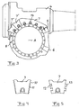
- Figure 2 illustrates how a device according to the invention is arranged for restricting the working range in the form of the maximum angle for rotation of an upper robot arm 4 relative to a lower robot arm 3 around an axis A.
- Two fixed stops 5, 6 with essentially tangentially directed stop surfaces, relative to the axis of rotation A, are arranged on the lower robot arm 3.
- the stops 5, 6 preferably consist of lugs formed when casting the body of the arm 3.
- the device further comprises a set of stop elements 7, 7', 7" in the form of blocks essentially shaped as truncated sectors of a circle, which are arranged to be placed in a row one after the other and making contact with one another on the upper arm 4, or a part secured thereto, along a circular arc around the axis of rotation A.
- the arm 4 exhibits first holes 8, distributed around the axis A, and the stop elements exhibit second holes 9 for inserting bolts 14, screws, or the like, for fixing the stop elements relative to the arm 4. In this way, upon rotation of the arm 4 around the axis A, the stop elements will hit against the stops 5 and 6, respectively, with end surfaces located at opposite ends of the rows, thus forming opposite end positions for the rotation.
- the set of stop elements may be combined in an arbitrary manner and be fixed by means of the fixing means (the screws) at different desired locations around the axis A, to define different desired end positions of the working range of the industrial robot around the axis A.
- the stop elements may, for example, exhibit a few, possibly only one, stop element adapted to extend through a relatively large angle along said circular arc, for example through 60°, preferably between 65° and 90°, whereas it may contain considerably more small stop elements with a corresponding angle of between 10° and 40°, preferably between 15° and 30°.
- members are provided for mutually connecting stop elements arranged adjacent to each other in said row so that these elements, with respect to transmission of forces between them and the stops 5, 6, when hitting against the stops upon rotation, behave essentially as if they together were one single coherent stop element.
- the connecting members are arranged on the stop elements themselves to bring about mechanical interlocking between adjacent stop elements, and in the embodiment illustrated in Figures 3 and 4 this is achieved by arranging tooth-like projections 10 on the essentially tangentially directed surfaces of the stop elements, when a row has been formed, and by forming recesses 11, corresponding thereto, on corresponding surfaces of adjacent stop elements.
- the teeth 10 and the recesses 11 are preferably elongated in the form of ridges and valleys, which ensures a very good interlock and transmission of forces therebetween, and it is especially preferred that they have an axial longitudinal extension in the position of the stop element around the axis.
- a tooth on one side of a stop element is preferably followed by a tooth in an exactly corresponding position of the stop element on the opposite side of this stop element.
- Figure 5 illustrates how the stop elements may exhibit different members for mutual mechanical interlocking, and here the tangentially directed ends of the stop elements are provided with essentially axially extending grooves 12 and projections 13 fitting therein and adapted to be inserted axially into these.
- the grooves and the projections exhibit a dovetail-shaped cross section, but other cross-section shapes are also feasible.
- the connecting members counteract relative motion of adjacent stop elements in a radial direction, so that when applying an essentially tangentially directed force to the front surface of a stop element, as viewed in the direction of movement, when hitting against a stop, this force may be forwarded from that stop element to the next as if this in practice constituted one coherent portion of the first stop element.
- the connecting members could also be formed from essentially tangentially directed fingers and corresponding recesses in the end surfaces of the respective stop element for insertion thereinto in an essentially tangential direction, such as for the teeth in the embodiment shown in Figure 4.
- the stop element blocks are advantageously made from extruded aluminium, which provides good possibilities of creating a complex two-dimensional geometry with good possibilities for tolerance.
- connecting members other than those shown and/or discussed above are possible, and it is within the scope of the invention, for example, to connect adjacently positioned stop elements to one another in other ways, so that they behave in this respect as if they were one single coherent stop element, than by mutual interlocking, such as by means of members which are completely separate from the stop elements and which are applied at the transition between adjacent stop elements, for example yoke-like elements with branches that are inserted into recesses in the respective stop elements or the like.
- interlocking seems to be preferable in most applications because of its simplicity and great reliability.
- stop elements are intended, with respect to the transmission of forces between them, to behave as one single coherent stop element, embraces all types of mutual connection between them which results in this behaviour but which allows subsequent detachment to enable the set of stop elements to be optionally combined again. Consequently, permanent gluing of the stop elements is not included.
- the teeth could be shaped like pyramids or cones or differ from ridges in some other way by interruptions, and the recesses could be modified in a corresponding way.
- the fixed stops could just as well be arranged on the upper arm and the stop elements on the lower arm.
- Damper layers for example of rubber, absorbing kinetic energy may be arranged on the surface of the stop and designed to be hit by the "foremost" stop element in the row and/or on the front surface of this stop element, as viewed in the direction of movement, and this is intended to be covered by the definition in the claim that the stop element hits against the stop.
Landscapes
- Engineering & Computer Science (AREA)
- Robotics (AREA)
- Mechanical Engineering (AREA)
- Manipulator (AREA)
- Spray Control Apparatus (AREA)
Claims (16)
- Vorrichtung zum Beschränken des Arbeitsbereichs um eine Achse eines Industrieroboters in Form einer Beschränkung des maximalen Winkels für die Rotation des ersten Teils (4) des Roboters, relativ zu einem zweiten Teil (3) davon, verbunden mit dem ersten Teil, wobei der Roboter ein fixiertes Anschlagsstück (5,6) aufweist, welches an dem zweiten Teil angeordnet ist, wobei die Vorrichtung eine Gruppe von Anschlagsstückelementen (7, 7', 7") aufweist, dadurch gekennzeichnet, dass sie weiter Mittel (8, 9, 14) aufweist, um eine optionale Anzahl von Anschlagsstückelementen auf dem ersten Teil (4) in einer Reihe nacheinander zu fixieren und sie, entlang eines Kreisbogens um die Rotationsachse des ersten Teils miteinander in Kontakt zu bringen, um gegen das Anschlagsstück mit diesen Endflächen der Anschlagsstückelemente zu treffen, die auf gegenüberliegenden Enden der Reihe angeordnet sind, wenn sich der erste Teil relativ zu dem zweiten Teil dreht, wodurch sich folglich gegenüberliegende Endstellungen für diese Drehung bilden, wobei die Vorrichtung weiter Elemente (10-13) für eine solche wechselseitige Verbindung der Anschlagsstückelemente (7, 7', 7") umfasst, welche benachbart zueinander in der Reihe angeordnet sind, dass diese Elemente, bezüglich der Übertragung von Kräften zwischen ihnen und dem Anschlagsstück (5, 6), wenn sie bei Drehung gegen die letzteren treffen, sich im wesentlichen so verhalten, als wären sie zusammen ein einzelnes kohärentes Anschlagstückelement.
- Vorrichtung gemäß Anspruch 1, dadurch gekennzeichnet, dass die Verbindungselemente (10-13), wenn sie die Reihe bilden, angepasst sind, um eine mechanische Verzahnung zwischen benachbarten Anschlagstückelementen (7, 7', 7") zu erzielen.
- Vorrichtung gemäß Anspruch 2, dadurch gekennzeichnet, dass die Verbindungselemente zahnähnliche Überstände (10), auf den im Wesentlichen tangential ausgerichteten Oberflächen der Anschlagsstückelemente, wenn eine Reihe gebildet wurde, und Aussparungen (11) umfassen, die dem an entsprechenden Oberflächen der benachbarten Anschlagsstückelemente entsprechen.
- Vorrichtung gemäß Anspruch 2, dadurch gekennzeichnet, dass die Verbindungselemente an den im Wesentlichen tangential gerichteten Enden der Anschlagsstückelemente, wenn eine Reihe gebildet worden ist, im Wesentlichen sich axial erstreckende Kerben oder Aussparungen bzw. Vertiefungen (12) und Überstände (13) aufweisen, die darin passen und angepasst sind, in diese eingesetzt zu werden.
- Vorrichtung gemäß irgendeinem der vorhergehenden Ansprüche, dadurch gekennzeichnet, dass das Befestigungsmittel erste Löcher (8) umfasst, die um die Rotationsachse des Arms in dem ersten Teil verteilt sind und zweite Löcher (9), die in den Anschlagstückelementen (7, 7', 7") angeordnet sind, sowie verlängerte stabförmige Stücke (14), die jeweils angepasst sind, um durch ein erstes und ein zweites Loch zum Befestigen der entsprechenden Anschlagsstückelemente in den ersten Teil eingesetzt zu werden.
- Vorrichtung gemäß Anspruch 5, dadurch gekennzeichnet, dass die Stücke Schrauben (14) sind, die für das Verschrauben der Anschlagsstückelemente (7, 7', 7") an das erste Teil bestimmt sind.
- Vorrichtung gemäß irgendeinem der vorhergehenden Ansprüche, dadurch gekennzeichnet, dass die Gruppe von Anschlagsstückelementen (7, 7', 7") Anschlagsstückelemente von gegenseitig beträchtlich verschiedenen Längen umfaßt, und zwar mit Bezug auf den Winkel, durch den sie sich entlang des Kreisbogens erstrecken sollen.
- Vorrichtung gemäß Anspruch 7, dadurch gekennzeichnet, dass die Gruppe 1-3 erste Anschlagsstückelemente (7) mit einem erheblich größeren Winkel einschließt, als die anderen Anschlagsstückelemente (7', 7"), welche in der Anzahl größer sind als die ersten.
- Vorrichtung gemäß Anspruch 8, dadurch gekennzeichnet, dass die Gruppe mindestens ein erstes Anschlagsstückelement (7) mit einem Winkel aufweist, der 60° überschreitet, vorzugsweise aber zwischen 65° und 90° liegt.
- Vorrichtung gemäß Anspruch 8 oder 9, dadurch gekennzeichnet, dass die Gruppe mehrere, vorzugsweise 3-6 andere Anschlagsstückelemente (7, 7', 7"), mit einem Winkel zwischen 10° und 40°, vorzugsweise aber zwischen 15° und 30° einschließt.
- Vorrichtung gemäß irgendeinem der vorhergehenden Ansprüche, dadurch gekennzeichnet, dass die Anschlagsstückelemente (7, 7', 7") aus Blöcken gebildet sind, welche im Wesentlichen die Form von abgeschnittenen Sektoren eines Kreises aufweisen.
- Vorrichtung gemäß irgendeinem der vorhergehenden Ansprüche, dadurch gekennzeichnet, dass die Mittel (8, 9, 14) angepasst sind, um die Anschlagsstückelemente an einem Arm eines Industrieroboters zu fixieren.
- Vorrichtung gemäß irgendeinem der vorhergehenden Ansprüche, dadurch gekennzeichnet, dass sie zur Anwendung auf ein Drehgelenk (A) zwischen ersten und zweiten Teilen, in der Form von zwei Armen (3, 4) eines Industrieroboters bestimmt ist.
- Vorrichtung gemäß irgendeinem der Ansprüche 1-11, dadurch gekennzeichnet, dass sie zur Anwendung auf ein Drehgelenk (C) in der Form eines Standes (1) und eines Roboterfußes (2) eines Industrieroboters, ausgelegt ist.
- Verfahren zum Bereitstellen einer Beschränkung des Arbeitsbereichs um die Achse eines Industrieroboters, in der Form der Beschränkung des maximalen Winkels der Drehung eines ersten Teils (4) des Roboters, relativ zu einem zweiten Teil (3) davon, welcher mit dem ersten Teil verbunden ist, wobei der Roboter ein fixiertes Anschlagsstück (5, 6) aufweist, welches bei dem zweiten Teil angeordnet ist, dadurch gekennzeichnet, dass eine optionale Anzahl einer Gruppe von Anschlagsstückelementen (7, 7', 7") an dem ersten Teil (4) in einer Reihe nacheinander befestigt ist und miteinander entlang eines Kreisbogens um die Rotationsachse des ersten Teils Kontakt bildet, um gegen das Anschlagsstück mit den Endoberflächen der Anschlagsstückelemente zu treffen, die an gegenüberliegenden Enden der Reihe angeordnet sind, wenn der sich erste Teil relativ zu dem zweiten Teil dreht, wodurch sich folglich gegenüberliegende Endstellungen für diese Rotation bilden, wobei die Anschlagsstückelemente (7, 7', 7"), welche benachbart zueinander in der Reihe angeordnet sind, gegenseitig miteinander in einer solchen Art und Weise verbunden sind, dass diese Anschlagsstückelemente, bezüglich der Übertragung von Kräften zwischen ihnen und dem Anschlagsstück (5, 6), wenn sie bei Drehung gegen die letzteren treffen, sich im wesentlichen so verhalten als wären sie zusammen ein einzelnes kohärentes Anschlagstückelement.
- Verfahren gemäß Anspruch 15, dadurch gekennzeichnet, dass benachbart angeordnete Anschlagsstückelemente gegenseitig miteinander dadurch verbunden werden, indem sie zusammengefügt werden, um eine gegenseitige Verzahnung von ihnen zu erreichen.
Applications Claiming Priority (3)
| Application Number | Priority Date | Filing Date | Title |
|---|---|---|---|
| SE0202176A SE524740C2 (sv) | 2002-07-11 | 2002-07-11 | Anordning och förfarande för rörelsebegränsning hos en industrirobot |
| SE0202176 | 2002-07-11 | ||
| PCT/SE2003/001171 WO2004007151A1 (en) | 2002-07-11 | 2003-07-04 | A device for an industrial robot |
Publications (2)
| Publication Number | Publication Date |
|---|---|
| EP1526952A1 EP1526952A1 (de) | 2005-05-04 |
| EP1526952B1 true EP1526952B1 (de) | 2007-11-07 |
Family
ID=20288508
Family Applications (1)
| Application Number | Title | Priority Date | Filing Date |
|---|---|---|---|
| EP03764270A Expired - Lifetime EP1526952B1 (de) | 2002-07-11 | 2003-07-04 | Vorrichtung für einen industrieroboter |
Country Status (7)
| Country | Link |
|---|---|
| US (1) | US20060224275A1 (de) |
| EP (1) | EP1526952B1 (de) |
| AT (1) | ATE377489T1 (de) |
| AU (1) | AU2003244291A1 (de) |
| DE (1) | DE60317335T2 (de) |
| SE (1) | SE524740C2 (de) |
| WO (1) | WO2004007151A1 (de) |
Families Citing this family (9)
| Publication number | Priority date | Publication date | Assignee | Title |
|---|---|---|---|---|
| JP4565029B2 (ja) * | 2008-08-13 | 2010-10-20 | ファナック株式会社 | 線条体動作制限装置、および該装置を備えたロボット |
| DE102012208430A1 (de) * | 2012-05-21 | 2013-11-21 | Kuka Roboter Gmbh | Industrieroboter mit einem ringförmigen Schleppanschlag |
| DE102017203741A1 (de) * | 2017-03-07 | 2018-09-13 | Kuka Deutschland Gmbh | Roboterarm mit einer mechanischen Anschlagsvorrichtung |
| JP6572254B2 (ja) | 2017-05-02 | 2019-09-04 | ファナック株式会社 | アーム固定装置および減速機交換方法 |
| JP6705794B2 (ja) * | 2017-12-01 | 2020-06-03 | ファナック株式会社 | ストッパを備えるロボット |
| WO2020165989A1 (ja) * | 2019-02-14 | 2020-08-20 | 株式会社Fuji | 多関節ロボット |
| JP7260398B2 (ja) * | 2019-05-24 | 2023-04-18 | ファナック株式会社 | アーム固定装置 |
| DE112019007680T5 (de) * | 2019-09-02 | 2022-06-15 | Yamaha Hatsudoki Kabushiki Kaisha | Roboter vom Armdrehtyp |
| CN118832565B (zh) * | 2024-08-26 | 2025-08-26 | 湖州瑞驰机械设备有限公司 | 一种流水线组装机器人用的手臂传动结构 |
Family Cites Families (15)
| Publication number | Priority date | Publication date | Assignee | Title |
|---|---|---|---|---|
| US2840651A (en) * | 1957-02-25 | 1958-06-24 | Budd Co | Rotary drum limit switch operating mechanism |
| US2863330A (en) * | 1957-04-05 | 1958-12-09 | John G Moorhead | Rotational setting mechanism |
| US3272031A (en) * | 1965-04-29 | 1966-09-13 | Mc Graw Edison Co | Adjustable stop for rotary selector switches |
| JPS5127064B1 (de) * | 1970-12-26 | 1976-08-10 | ||
| US3954188A (en) * | 1973-12-26 | 1976-05-04 | Prab Conveyors, Inc. | Universal transfer device |
| US3896681A (en) * | 1973-12-26 | 1975-07-29 | Prab Conveyors | Universal transfer device |
| JPS5898193U (ja) * | 1981-12-25 | 1983-07-04 | 株式会社岡村製作所 | 工業用ロボツトア−ムの多点停止装置 |
| US4564331A (en) * | 1983-01-17 | 1986-01-14 | Karr Ake Wendell | Robot |
| JPS6228194A (ja) * | 1985-07-29 | 1987-02-06 | フアナツク株式会社 | 工業用ロボツトの動作範囲規制装置 |
| JPH07121513B2 (ja) * | 1986-10-17 | 1995-12-25 | フアナツク株式会社 | 産業用ロボツトの旋回胴旋回域設定装置 |
| DE3721274A1 (de) * | 1987-06-27 | 1989-01-12 | Fraunhofer Ges Forschung | Vorrichtung zur begrenzung des schwenkbereiches von rotatorisch bewegbaren bauteilen |
| SE469878B (sv) * | 1991-02-11 | 1993-10-04 | Asea Brown Boveri | Justerbar stoppanordning för industrirobot |
| CN1052937C (zh) * | 1995-09-18 | 2000-05-31 | 株式会社安川电机 | 工业机器人的止挡装置 |
| US5839322A (en) * | 1996-01-26 | 1998-11-24 | Genmark Automation | Robotic arm rotation controller |
| KR200145221Y1 (ko) * | 1996-07-30 | 1999-06-15 | 윤종용 | 로봇 회전관절 스토퍼 |
-
2002
- 2002-07-11 SE SE0202176A patent/SE524740C2/sv not_active IP Right Cessation
-
2003
- 2003-07-04 US US10/520,919 patent/US20060224275A1/en not_active Abandoned
- 2003-07-04 WO PCT/SE2003/001171 patent/WO2004007151A1/en not_active Ceased
- 2003-07-04 AU AU2003244291A patent/AU2003244291A1/en not_active Abandoned
- 2003-07-04 AT AT03764270T patent/ATE377489T1/de not_active IP Right Cessation
- 2003-07-04 EP EP03764270A patent/EP1526952B1/de not_active Expired - Lifetime
- 2003-07-04 DE DE60317335T patent/DE60317335T2/de not_active Expired - Lifetime
Also Published As
| Publication number | Publication date |
|---|---|
| ATE377489T1 (de) | 2007-11-15 |
| DE60317335T2 (de) | 2008-02-21 |
| SE524740C2 (sv) | 2004-09-21 |
| WO2004007151A1 (en) | 2004-01-22 |
| AU2003244291A1 (en) | 2004-02-02 |
| DE60317335D1 (de) | 2007-12-20 |
| EP1526952A1 (de) | 2005-05-04 |
| SE0202176D0 (sv) | 2002-07-11 |
| US20060224275A1 (en) | 2006-10-05 |
| SE0202176L (sv) | 2004-01-12 |
Similar Documents
| Publication | Publication Date | Title |
|---|---|---|
| EP1526952B1 (de) | Vorrichtung für einen industrieroboter | |
| JP4366022B2 (ja) | ピンで固定されたバーをを有するワイヤーアイソレータ及びその製造方法 | |
| EP3683936B1 (de) | Systeme und verfahren zur axialen schlagfestigkeit in elektromotoren | |
| EP0087116B1 (de) | Ständer mit elastischer Aufhängung für dynamo-elektrische Synchronmaschinen | |
| JPH0314095B2 (de) | ||
| WO2004054068A3 (en) | Rotor for line-start reluctance motor | |
| KR20130069817A (ko) | 풍차 회전 날개 | |
| GB2355486A (en) | Fastening device for interconnecting two parts | |
| CA2215765A1 (en) | Rotors and methods of manufacturing such rotors | |
| EP0471499A1 (de) | Ausgleichsgetriebeeinheit | |
| EP1183473A1 (de) | Verbindungssystem für leichte, modulare lasttragstrukturen | |
| US20010019697A1 (en) | Fastening rotor blades in a turbomachine | |
| KR20170130411A (ko) | 공간 구조체 | |
| JP2005538298A (ja) | 偏心スパイラルポンプ用ステータ | |
| EP1061233A3 (de) | Gasturbinenrotorverbindung | |
| US11473252B2 (en) | Protection system for tension members | |
| WO2017220095A1 (en) | A wind turbine nacelle comprising a rear frame structure with flexible joints | |
| CN107388016B (zh) | 一种拼装结构 | |
| EP3812314A1 (de) | Verbessertes modulares förderband | |
| WO2010106228A1 (en) | Piston pin and a piston - piston pin combination | |
| KR200250676Y1 (ko) | 조립식 간이 구조물용 프레임 연결구 | |
| KR200173857Y1 (ko) | 플랙시블 커프링의 고정 플레이트 결속구조 | |
| EP2604855A1 (de) | Rotor für einen Generator | |
| KR100228616B1 (ko) | 플렉시블 커플링 완충부재 및 그 제조방법 | |
| EP1815572B1 (de) | Verbindungsvorrichtung für kabelkanäle |
Legal Events
| Date | Code | Title | Description |
|---|---|---|---|
| PUAI | Public reference made under article 153(3) epc to a published international application that has entered the european phase |
Free format text: ORIGINAL CODE: 0009012 |
|
| 17P | Request for examination filed |
Effective date: 20041221 |
|
| AK | Designated contracting states |
Kind code of ref document: A1 Designated state(s): AT BE BG CH CY CZ DE DK EE ES FI FR GB GR HU IE IT LI LU MC NL PT RO SE SI SK TR |
|
| AX | Request for extension of the european patent |
Extension state: AL LT LV MK |
|
| DAX | Request for extension of the european patent (deleted) | ||
| GRAP | Despatch of communication of intention to grant a patent |
Free format text: ORIGINAL CODE: EPIDOSNIGR1 |
|
| GRAS | Grant fee paid |
Free format text: ORIGINAL CODE: EPIDOSNIGR3 |
|
| GRAA | (expected) grant |
Free format text: ORIGINAL CODE: 0009210 |
|
| AK | Designated contracting states |
Kind code of ref document: B1 Designated state(s): AT BE BG CH CY CZ DE DK EE ES FI FR GB GR HU IE IT LI LU MC NL PT RO SE SI SK TR |
|
| REG | Reference to a national code |
Ref country code: GB Ref legal event code: FG4D |
|
| REG | Reference to a national code |
Ref country code: IE Ref legal event code: FG4D |
|
| REG | Reference to a national code |
Ref country code: CH Ref legal event code: EP |
|
| REF | Corresponds to: |
Ref document number: 60317335 Country of ref document: DE Date of ref document: 20071220 Kind code of ref document: P |
|
| PG25 | Lapsed in a contracting state [announced via postgrant information from national office to epo] |
Ref country code: NL Free format text: LAPSE BECAUSE OF FAILURE TO SUBMIT A TRANSLATION OF THE DESCRIPTION OR TO PAY THE FEE WITHIN THE PRESCRIBED TIME-LIMIT Effective date: 20071107 Ref country code: CH Free format text: LAPSE BECAUSE OF FAILURE TO SUBMIT A TRANSLATION OF THE DESCRIPTION OR TO PAY THE FEE WITHIN THE PRESCRIBED TIME-LIMIT Effective date: 20071107 Ref country code: ES Free format text: LAPSE BECAUSE OF FAILURE TO SUBMIT A TRANSLATION OF THE DESCRIPTION OR TO PAY THE FEE WITHIN THE PRESCRIBED TIME-LIMIT Effective date: 20080218 Ref country code: SE Free format text: LAPSE BECAUSE OF FAILURE TO SUBMIT A TRANSLATION OF THE DESCRIPTION OR TO PAY THE FEE WITHIN THE PRESCRIBED TIME-LIMIT Effective date: 20080207 Ref country code: LI Free format text: LAPSE BECAUSE OF FAILURE TO SUBMIT A TRANSLATION OF THE DESCRIPTION OR TO PAY THE FEE WITHIN THE PRESCRIBED TIME-LIMIT Effective date: 20071107 |
|
| NLV1 | Nl: lapsed or annulled due to failure to fulfill the requirements of art. 29p and 29m of the patents act | ||
| PG25 | Lapsed in a contracting state [announced via postgrant information from national office to epo] |
Ref country code: BG Free format text: LAPSE BECAUSE OF FAILURE TO SUBMIT A TRANSLATION OF THE DESCRIPTION OR TO PAY THE FEE WITHIN THE PRESCRIBED TIME-LIMIT Effective date: 20080207 Ref country code: SI Free format text: LAPSE BECAUSE OF FAILURE TO SUBMIT A TRANSLATION OF THE DESCRIPTION OR TO PAY THE FEE WITHIN THE PRESCRIBED TIME-LIMIT Effective date: 20071107 |
|
| REG | Reference to a national code |
Ref country code: CH Ref legal event code: PL |
|
| PG25 | Lapsed in a contracting state [announced via postgrant information from national office to epo] |
Ref country code: AT Free format text: LAPSE BECAUSE OF FAILURE TO SUBMIT A TRANSLATION OF THE DESCRIPTION OR TO PAY THE FEE WITHIN THE PRESCRIBED TIME-LIMIT Effective date: 20071107 |
|
| PG25 | Lapsed in a contracting state [announced via postgrant information from national office to epo] |
Ref country code: DK Free format text: LAPSE BECAUSE OF FAILURE TO SUBMIT A TRANSLATION OF THE DESCRIPTION OR TO PAY THE FEE WITHIN THE PRESCRIBED TIME-LIMIT Effective date: 20071107 Ref country code: CZ Free format text: LAPSE BECAUSE OF FAILURE TO SUBMIT A TRANSLATION OF THE DESCRIPTION OR TO PAY THE FEE WITHIN THE PRESCRIBED TIME-LIMIT Effective date: 20071107 |
|
| PG25 | Lapsed in a contracting state [announced via postgrant information from national office to epo] |
Ref country code: SK Free format text: LAPSE BECAUSE OF FAILURE TO SUBMIT A TRANSLATION OF THE DESCRIPTION OR TO PAY THE FEE WITHIN THE PRESCRIBED TIME-LIMIT Effective date: 20071107 Ref country code: RO Free format text: LAPSE BECAUSE OF FAILURE TO SUBMIT A TRANSLATION OF THE DESCRIPTION OR TO PAY THE FEE WITHIN THE PRESCRIBED TIME-LIMIT Effective date: 20071107 Ref country code: BE Free format text: LAPSE BECAUSE OF FAILURE TO SUBMIT A TRANSLATION OF THE DESCRIPTION OR TO PAY THE FEE WITHIN THE PRESCRIBED TIME-LIMIT Effective date: 20071107 |
|
| PLBE | No opposition filed within time limit |
Free format text: ORIGINAL CODE: 0009261 |
|
| STAA | Information on the status of an ep patent application or granted ep patent |
Free format text: STATUS: NO OPPOSITION FILED WITHIN TIME LIMIT |
|
| PG25 | Lapsed in a contracting state [announced via postgrant information from national office to epo] |
Ref country code: PT Free format text: LAPSE BECAUSE OF FAILURE TO SUBMIT A TRANSLATION OF THE DESCRIPTION OR TO PAY THE FEE WITHIN THE PRESCRIBED TIME-LIMIT Effective date: 20080407 |
|
| 26N | No opposition filed |
Effective date: 20080808 |
|
| PG25 | Lapsed in a contracting state [announced via postgrant information from national office to epo] |
Ref country code: GR Free format text: LAPSE BECAUSE OF FAILURE TO SUBMIT A TRANSLATION OF THE DESCRIPTION OR TO PAY THE FEE WITHIN THE PRESCRIBED TIME-LIMIT Effective date: 20080208 |
|
| PG25 | Lapsed in a contracting state [announced via postgrant information from national office to epo] |
Ref country code: FI Free format text: LAPSE BECAUSE OF FAILURE TO SUBMIT A TRANSLATION OF THE DESCRIPTION OR TO PAY THE FEE WITHIN THE PRESCRIBED TIME-LIMIT Effective date: 20071107 |
|
| GBPC | Gb: european patent ceased through non-payment of renewal fee |
Effective date: 20080704 |
|
| PG25 | Lapsed in a contracting state [announced via postgrant information from national office to epo] |
Ref country code: MC Free format text: LAPSE BECAUSE OF NON-PAYMENT OF DUE FEES Effective date: 20080731 |
|
| PG25 | Lapsed in a contracting state [announced via postgrant information from national office to epo] |
Ref country code: EE Free format text: LAPSE BECAUSE OF FAILURE TO SUBMIT A TRANSLATION OF THE DESCRIPTION OR TO PAY THE FEE WITHIN THE PRESCRIBED TIME-LIMIT Effective date: 20071107 |
|
| PG25 | Lapsed in a contracting state [announced via postgrant information from national office to epo] |
Ref country code: GB Free format text: LAPSE BECAUSE OF NON-PAYMENT OF DUE FEES Effective date: 20080704 |
|
| PG25 | Lapsed in a contracting state [announced via postgrant information from national office to epo] |
Ref country code: IE Free format text: LAPSE BECAUSE OF NON-PAYMENT OF DUE FEES Effective date: 20080704 Ref country code: CY Free format text: LAPSE BECAUSE OF FAILURE TO SUBMIT A TRANSLATION OF THE DESCRIPTION OR TO PAY THE FEE WITHIN THE PRESCRIBED TIME-LIMIT Effective date: 20071107 |
|
| PG25 | Lapsed in a contracting state [announced via postgrant information from national office to epo] |
Ref country code: HU Free format text: LAPSE BECAUSE OF FAILURE TO SUBMIT A TRANSLATION OF THE DESCRIPTION OR TO PAY THE FEE WITHIN THE PRESCRIBED TIME-LIMIT Effective date: 20080508 Ref country code: LU Free format text: LAPSE BECAUSE OF NON-PAYMENT OF DUE FEES Effective date: 20080704 |
|
| PG25 | Lapsed in a contracting state [announced via postgrant information from national office to epo] |
Ref country code: TR Free format text: LAPSE BECAUSE OF FAILURE TO SUBMIT A TRANSLATION OF THE DESCRIPTION OR TO PAY THE FEE WITHIN THE PRESCRIBED TIME-LIMIT Effective date: 20071107 |
|
| PGFP | Annual fee paid to national office [announced via postgrant information from national office to epo] |
Ref country code: FR Payment date: 20110727 Year of fee payment: 9 |
|
| PGFP | Annual fee paid to national office [announced via postgrant information from national office to epo] |
Ref country code: IT Payment date: 20110729 Year of fee payment: 9 |
|
| PGFP | Annual fee paid to national office [announced via postgrant information from national office to epo] |
Ref country code: DE Payment date: 20120627 Year of fee payment: 10 |
|
| REG | Reference to a national code |
Ref country code: FR Ref legal event code: ST Effective date: 20130329 |
|
| PG25 | Lapsed in a contracting state [announced via postgrant information from national office to epo] |
Ref country code: FR Free format text: LAPSE BECAUSE OF NON-PAYMENT OF DUE FEES Effective date: 20120731 |
|
| PG25 | Lapsed in a contracting state [announced via postgrant information from national office to epo] |
Ref country code: IT Free format text: LAPSE BECAUSE OF NON-PAYMENT OF DUE FEES Effective date: 20120704 |
|
| REG | Reference to a national code |
Ref country code: DE Ref legal event code: R119 Ref document number: 60317335 Country of ref document: DE Effective date: 20140201 |
|
| PG25 | Lapsed in a contracting state [announced via postgrant information from national office to epo] |
Ref country code: DE Free format text: LAPSE BECAUSE OF NON-PAYMENT OF DUE FEES Effective date: 20140201 |