EP1526948B1 - Durch magnetorheologische feinstbearbeitung hergestellte gleichförmige dünne filme - Google Patents
Durch magnetorheologische feinstbearbeitung hergestellte gleichförmige dünne filme Download PDFInfo
- Publication number
- EP1526948B1 EP1526948B1 EP03755733A EP03755733A EP1526948B1 EP 1526948 B1 EP1526948 B1 EP 1526948B1 EP 03755733 A EP03755733 A EP 03755733A EP 03755733 A EP03755733 A EP 03755733A EP 1526948 B1 EP1526948 B1 EP 1526948B1
- Authority
- EP
- European Patent Office
- Prior art keywords
- thickness
- layer
- working layer
- accordance
- layer element
- Prior art date
- Legal status (The legal status is an assumption and is not a legal conclusion. Google has not performed a legal analysis and makes no representation as to the accuracy of the status listed.)
- Expired - Lifetime
Links
- 239000010409 thin film Substances 0.000 title description 5
- 239000000758 substrate Substances 0.000 claims abstract description 30
- 239000000463 material Substances 0.000 claims abstract description 17
- 238000000034 method Methods 0.000 claims description 16
- 229910052710 silicon Inorganic materials 0.000 claims description 13
- 239000010703 silicon Substances 0.000 claims description 13
- XUIMIQQOPSSXEZ-UHFFFAOYSA-N Silicon Chemical compound [Si] XUIMIQQOPSSXEZ-UHFFFAOYSA-N 0.000 claims description 12
- 239000011521 glass Substances 0.000 claims description 8
- 229910045601 alloy Inorganic materials 0.000 claims description 4
- 239000000956 alloy Substances 0.000 claims description 4
- 239000000919 ceramic Substances 0.000 claims description 4
- 229910052751 metal Inorganic materials 0.000 claims description 4
- 239000002184 metal Substances 0.000 claims description 4
- 150000002739 metals Chemical class 0.000 claims description 4
- 150000004767 nitrides Chemical class 0.000 claims description 4
- TWNQGVIAIRXVLR-UHFFFAOYSA-N oxo(oxoalumanyloxy)alumane Chemical compound O=[Al]O[Al]=O TWNQGVIAIRXVLR-UHFFFAOYSA-N 0.000 claims description 4
- 229910052594 sapphire Inorganic materials 0.000 claims description 4
- 239000010980 sapphire Substances 0.000 claims description 4
- JBRZTFJDHDCESZ-UHFFFAOYSA-N AsGa Chemical compound [As]#[Ga] JBRZTFJDHDCESZ-UHFFFAOYSA-N 0.000 claims description 3
- 229910001218 Gallium arsenide Inorganic materials 0.000 claims description 3
- 150000001247 metal acetylides Chemical class 0.000 claims description 3
- 229910000314 transition metal oxide Inorganic materials 0.000 claims description 3
- WFKWXMTUELFFGS-UHFFFAOYSA-N tungsten Chemical compound [W] WFKWXMTUELFFGS-UHFFFAOYSA-N 0.000 claims description 3
- 229910052721 tungsten Inorganic materials 0.000 claims description 3
- 239000010937 tungsten Substances 0.000 claims description 3
- 238000007730 finishing process Methods 0.000 claims 2
- 239000004065 semiconductor Substances 0.000 claims 1
- 238000004519 manufacturing process Methods 0.000 abstract description 7
- 238000002441 X-ray diffraction Methods 0.000 abstract description 2
- 238000000572 ellipsometry Methods 0.000 abstract description 2
- 238000004556 laser interferometry Methods 0.000 abstract description 2
- 239000010410 layer Substances 0.000 description 47
- 239000012530 fluid Substances 0.000 description 11
- 238000000576 coating method Methods 0.000 description 9
- 238000005516 engineering process Methods 0.000 description 5
- 239000011248 coating agent Substances 0.000 description 4
- 230000003287 optical effect Effects 0.000 description 4
- 238000005498 polishing Methods 0.000 description 3
- -1 but not limited to Substances 0.000 description 2
- 238000005336 cracking Methods 0.000 description 2
- 239000012212 insulator Substances 0.000 description 2
- 238000012876 topography Methods 0.000 description 2
- 206010017076 Fracture Diseases 0.000 description 1
- 208000013201 Stress fracture Diseases 0.000 description 1
- 230000001419 dependent effect Effects 0.000 description 1
- 229910003460 diamond Inorganic materials 0.000 description 1
- 239000010432 diamond Substances 0.000 description 1
- 239000010408 film Substances 0.000 description 1
- 239000007788 liquid Substances 0.000 description 1
- 238000004377 microelectronic Methods 0.000 description 1
- 239000002245 particle Substances 0.000 description 1
- 230000002093 peripheral effect Effects 0.000 description 1
- 239000011241 protective layer Substances 0.000 description 1
- 238000000926 separation method Methods 0.000 description 1
- 239000007787 solid Substances 0.000 description 1
- 238000003860 storage Methods 0.000 description 1
- 239000000126 substance Substances 0.000 description 1
- 238000004804 winding Methods 0.000 description 1
- 238000002424 x-ray crystallography Methods 0.000 description 1
Images
Classifications
-
- B—PERFORMING OPERATIONS; TRANSPORTING
- B24—GRINDING; POLISHING
- B24B—MACHINES, DEVICES, OR PROCESSES FOR GRINDING OR POLISHING; DRESSING OR CONDITIONING OF ABRADING SURFACES; FEEDING OF GRINDING, POLISHING, OR LAPPING AGENTS
- B24B49/00—Measuring or gauging equipment for controlling the feed movement of the grinding tool or work; Arrangements of indicating or measuring equipment, e.g. for indicating the start of the grinding operation
- B24B49/12—Measuring or gauging equipment for controlling the feed movement of the grinding tool or work; Arrangements of indicating or measuring equipment, e.g. for indicating the start of the grinding operation involving optical means
-
- B—PERFORMING OPERATIONS; TRANSPORTING
- B24—GRINDING; POLISHING
- B24B—MACHINES, DEVICES, OR PROCESSES FOR GRINDING OR POLISHING; DRESSING OR CONDITIONING OF ABRADING SURFACES; FEEDING OF GRINDING, POLISHING, OR LAPPING AGENTS
- B24B1/00—Processes of grinding or polishing; Use of auxiliary equipment in connection with such processes
- B24B1/005—Processes of grinding or polishing; Use of auxiliary equipment in connection with such processes using a magnetic polishing agent
-
- B—PERFORMING OPERATIONS; TRANSPORTING
- B24—GRINDING; POLISHING
- B24B—MACHINES, DEVICES, OR PROCESSES FOR GRINDING OR POLISHING; DRESSING OR CONDITIONING OF ABRADING SURFACES; FEEDING OF GRINDING, POLISHING, OR LAPPING AGENTS
- B24B31/00—Machines or devices designed for polishing or abrading surfaces on work by means of tumbling apparatus or other apparatus in which the work and/or the abrasive material is loose; Accessories therefor
- B24B31/10—Machines or devices designed for polishing or abrading surfaces on work by means of tumbling apparatus or other apparatus in which the work and/or the abrasive material is loose; Accessories therefor involving other means for tumbling of work
- B24B31/112—Machines or devices designed for polishing or abrading surfaces on work by means of tumbling apparatus or other apparatus in which the work and/or the abrasive material is loose; Accessories therefor involving other means for tumbling of work using magnetically consolidated grinding powder, moved relatively to the workpiece under the influence of pressure
-
- B—PERFORMING OPERATIONS; TRANSPORTING
- B24—GRINDING; POLISHING
- B24B—MACHINES, DEVICES, OR PROCESSES FOR GRINDING OR POLISHING; DRESSING OR CONDITIONING OF ABRADING SURFACES; FEEDING OF GRINDING, POLISHING, OR LAPPING AGENTS
- B24B7/00—Machines or devices designed for grinding plane surfaces on work, including polishing plane glass surfaces; Accessories therefor
- B24B7/20—Machines or devices designed for grinding plane surfaces on work, including polishing plane glass surfaces; Accessories therefor characterised by a special design with respect to properties of the material of non-metallic articles to be ground
- B24B7/22—Machines or devices designed for grinding plane surfaces on work, including polishing plane glass surfaces; Accessories therefor characterised by a special design with respect to properties of the material of non-metallic articles to be ground for grinding inorganic material, e.g. stone, ceramics, porcelain
- B24B7/228—Machines or devices designed for grinding plane surfaces on work, including polishing plane glass surfaces; Accessories therefor characterised by a special design with respect to properties of the material of non-metallic articles to be ground for grinding inorganic material, e.g. stone, ceramics, porcelain for grinding thin, brittle parts, e.g. semiconductors, wafers
-
- G—PHYSICS
- G01—MEASURING; TESTING
- G01B—MEASURING LENGTH, THICKNESS OR SIMILAR LINEAR DIMENSIONS; MEASURING ANGLES; MEASURING AREAS; MEASURING IRREGULARITIES OF SURFACES OR CONTOURS
- G01B11/00—Measuring arrangements characterised by the use of optical techniques
- G01B11/02—Measuring arrangements characterised by the use of optical techniques for measuring length, width or thickness
- G01B11/06—Measuring arrangements characterised by the use of optical techniques for measuring length, width or thickness for measuring thickness ; e.g. of sheet material
-
- G—PHYSICS
- G01—MEASURING; TESTING
- G01B—MEASURING LENGTH, THICKNESS OR SIMILAR LINEAR DIMENSIONS; MEASURING ANGLES; MEASURING AREAS; MEASURING IRREGULARITIES OF SURFACES OR CONTOURS
- G01B11/00—Measuring arrangements characterised by the use of optical techniques
- G01B11/30—Measuring arrangements characterised by the use of optical techniques for measuring roughness or irregularity of surfaces
- G01B11/306—Measuring arrangements characterised by the use of optical techniques for measuring roughness or irregularity of surfaces for measuring evenness
Definitions
- the present invention relates to production of thin films; more particularly, to such films having a high degree of thickness uniformity; and most particularly, to a method wherein an magnetorheological fluid finishing system programmably removes material from a thin layer, which may have been previously coated to a non-uniform substrate to leave a layer having a very high level of thickness uniformity.
- Magnetically-stiffened magnetorheological fluids for abrasive finishing and polishing of substrates is well known.
- Such fluids containing magnetically-soft abrasive particles dispersed in a liquid carrier, exhibit magnetically-induced plastic behavior in the presence of a magnetic field.
- the apparent viscosity of the fluid can be magnetically increased by many orders of magnitude, such that the consistency of the fluid changes from being nearly watery to being a very stiff paste.
- a typical MRF finishing system is the QED Technologies Q22 MRF System, available from QED Technologies, Rochester, New York, USA.
- a work surface comprises a vertically-oriented wheel having an axially-wide rim which is undercut symmetrically about a hub.
- Specially shaped magnetic pole pieces are extended toward opposite sides of the wheel under the undercut rim to provide a magnetic work zone on the surface of the wheel, preferably at about the top-dead-center position.
- the surface of the wheel is preferably an equatorial section of a sphere.
- the finishing system may be programmed to move the work holder in a plurality of modes and speeds of motion to remove more or less material from the workpiece by varying the areal location of work and speed of travel of the workpiece through the work zone, and therefore the exposure time in the work zone.
- the finishing may be carried out at any desired angular orientation of the work zone on the carrier wheel, e.g., the workpiece may be positioned on a controllable bed, the carrier wheel positioned over the substrate, and a work zone provided at the bottom dead center position on the carrier wheel.
- a serious problem can arise, however, in producing coatings requiring a very high level of thickness uniformity and surface integrity.
- Non-planarities in the substrate may not be followed conformably by the coatings but may tend to be filled in or rounded in the free surface of the coatings; thus, an actual coating may undesirably have thicker and thinner areas, depending upon the topography of the substrate to which it is coated.
- producing coatings of extreme thickness uniformity and surface integrity can require very complicated manufacturing process including chemical - mechanical polishing.
- the criterion for suitability of such a coating is not its absolute level of flatness but rather its absolute thickness, level of thickness uniformity, and level of surface integrity.
- US 5 951 361 A discloses a system for increasing the effectiveness of magnetorheological finishing of a substrate.
- An inline flowmeter is linked to the rotational speed of a pressurizing pump to assure that the flow of magnetorheological fluid to the work zone is constant.
- a capillary viscometer is disposed in the fluid delivery system. Output signals from the flowmeter and the viscometer pressure sensor are sent to a computer which calculates the viscosity of the magnetorheological fluid and causes replenishment of carrier fluid to the work-concentrated magnetorheological fluid to return the viscosity in order to maintain a constant concentration of magnetic solids in the work zone.
- US 5 488 477 A discloses an optical system for measuring the front and back surface topography of transparent objects with substantially parallel surfaces which includes an interferometer, an electronic camera, and digital signal processing means for determining surface height from interference data. Measuring methods for use with the optical system permit the mathematical separation of the interference contributions due to the multiple reflections from the two parallel surfaces of the object.
- a working layer of the material is formed at a thickness greater than the final thickness desired.
- the layer may be an independent element or may be formed as a coating on a carrier substrate.
- An areal (XY) determination of working layer thickness is made by a known technique, such as ellipsometry, laser interferometry, or x-ray diffraction.
- a currently preferred means is an AcuMap II device, available from ADE Technologies, Inc., Newton, Massachusetts, USA. Data representing a map of thicknesses to be removed from the free surface of the working layer are entered into the control system of a magnetorheological finishing apparatus.
- the independent layer element or the coated substrate element is mounted on as workpiece holder of the apparatus and correctly indexed to the machine.
- the MRF machine then removes material as instructed by the control system to leave a residual layer having a very high degree of thickness uniformity at a nominal average thickness and having a very high level of surface integrity.
- the invention is useful in providing thin films of materials including, but not limited to, ceramics, glass, metals, transition metal oxides, magnetoresistive alloys, aluminum oxide, nitrides, carbides, gallium arsenide, tungsten, silicon, and sapphire.
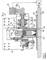
- magnetorheological finishing system 10 suitable for use in a method in accordance with the invention (for example, a Q22 System available from QED Technologies, Rochester, New York, USA) includes a base 12 and first arm 15 for supporting a magnet assembly 17.
- Assembly 17 includes the core and windings 13 of an electromagnet and left and right magnet yoke members 14,16, respectively, which are preferably planar slabs having radial ends conformable to spherical carrier wheel 20, and which are connected conventionally to the core.
- Second bracket 11 extending from base 12 supports a shaft 22 journalled in bearings 24 and a motor drive unit 18 cantilevered therefrom.
- Drive unit 18 is controlled by a drive controller (not shown) in conventional fashion to control the rotational speed of the drive at a desired aim.
- Drive unit 18 is further connected to a system controller 19 for coordinating the actions of the various components of the system.
- Shaft 22 is rotatably coupled to a carrier wheel flange 30 supporting a peripheral surface 32 which extends from flange 30 in the direction away from drive unit 18.
- Flange 30 and surface 32 together define a generally bowl-shaped carrier wheel 20 which is open on the side opposite flange 30 for receiving magnet assembly 17.
- surface 32 is an equatorial section of a sphere.
- An application nozzle (not visible in the cross-section shown in FIG. 1 ⁇ provides a ribbon of magnetorheological fluid onto moving work surface 32 in known fashion.
- the apparatus is arranged as shown in FIG. 1 so that a work zone 58 can be formed at the bottom dead center position of carrier wheel 20 for finishing of planar substrates which may conveniently be mounted on a substage or bed 62 operationally connected to a computer-controlled 5-axis positioning machine 64 in known fashion, whereby the speed and direction of a planar substrate with respect to the work zone 58 may be precisely controlled.
- Machine 64 is a subsystem and integral part of magnetorheological finishing system 10 and is controlled by system controller 19.
- a substrate may be mounted as desired at any angle to surface 32, in accordance with known technology.
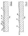
- a substrate 66 having a non-planar upper surface 68 (vertical scale of non-planarities highly exaggerated for illustration) is coated with a working layer 70 of a material to be finished into a highly uniform layer 72 in accordance with the invention.
- the working layer may optionally be provided with an undercoat on surface 68, for example, to promote adhesion of 70 thereto or to electrically or optically insulate working layer 70 from the substrate; such an optional undercoat should be understood, although it is omitted from the drawings for clarity of presentation.
- Working layer 70 first is characterized in known fashion by a conventional thin-film measuring device, such as an x-ray crystallography machine, a laser interferometer, or an ellipsometer, and an areal (two-dimensional) data map of coated layer 70 is generated for thickness variations 74 between an upper surface 76 of layer 70 and substrate surface 68.
- the value of the desired thickness 78 is subtracted from each entered thickness data value, yielding by subtraction an areal thickness map of material to be removed 80 from layer 70 to result in uniform layer 72, which map is programmed into system 10.
- Substrate 66 is mounted onto bed 62 and is indexed to system 10 such that the amounts of layer 70 to be removed will be removed from the correct areas. System 10 then proceeds to follow the programmed removal map by varying the direction and translation speed of bed 62 in known fashion. When all of material 80 has been removed, uniform layer 72 having free surface 82 is the result.
- layer 72 is uniform in thickness within +/- 5 nm or less.
- the desired finished thickness of the silicon layer is 100 nm.
- the working layer thickness is areally characterized and a removal pattern is programmed into a QED Q22 System.
- the wafer is mounted in the workpiece holder, indexed to the calculated removal pattern, and the removal pattern is carried out, leaving a finished residual silicon layer having a nominal thickness of 100 nm and a variation in thickness of less than +/- 5 nm.
- the surface is free of stress-induced cracks.
- the thickness variation of the working element may be similarly characterized, using internal reflection from the back surface of the element.
- independent elements up to, for example, several millimeters in thickness may be finished to a desired thickness having peak-to-valley (PV) differences sometimes referred as TTV (total thickness variation) of no more than 50 nm, and, in some instances, less than 10 nm.
- PV peak-to-valley
- magnetoresistive alloy layers may be finished to very high thickness uniformities for use in read-write heads in the magnetic storage art.
- extremely hard coatings of materials such as diamond, aluminum oxide, and nitrides may be finished for use as wear-protective layers on otherwise vulnerable elements subject to abrasive damage in use.
- the invention is useful in providing thin films of a wide range of materials including, but not limited to, ceramics, glass, metals, transition metal oxides, magnetoresistive alloys, aluminum oxide, nitrides, carbides, gallium arsenide, tungsten, silicon, and sapphire.
Landscapes
- Engineering & Computer Science (AREA)
- Mechanical Engineering (AREA)
- Physics & Mathematics (AREA)
- General Physics & Mathematics (AREA)
- Chemical & Material Sciences (AREA)
- Ceramic Engineering (AREA)
- Inorganic Chemistry (AREA)
- Finish Polishing, Edge Sharpening, And Grinding By Specific Grinding Devices (AREA)
- Mechanical Treatment Of Semiconductor (AREA)
- Physical Vapour Deposition (AREA)
- Surface Treatment Of Glass (AREA)
Claims (7)
- Verfahren zum Vorsehen eines Restschichtelementes (72) mit einer erwünschten Dicke und einem hohen Grad an Dickengleichförmigkeit durch einen magnetorheologischen Endbearbeitungsprozess (10) eines Arbeitsschichtelementes (70) von bekannter Dicke, welches eine zweidimensionale Karte der tatsächlichen Arbeitsschichtdicke (74) aufweist, wobei das Verfahren gekennzeichnet ist durch:a) Subtrahieren der erwünschten Dicke von der zweidimensionalen Karte der tatsächlichen Arbeitsschichtdicke (74), um eine zweidimensionale Dickenkarte des von dem Arbeitsschichtelement (70) zu entfernenden Materials zu erhalten; undb) Einsetzen des magnetorheologischen Endbearbeitungsprozesses (10), um das Material gemäß der zweidimensionalen Karte der zu entfernenden Materialdicke zu entfernen, um das Restschichtelement (72) zu formen.
- Verfahren nach Anspruch 1, wobei das Arbeitsschichtelement (70) auf einem Trägersubstrat (66) vorbeschichtet ist.
- Verfahren nach Anspruch 2, wobei das Trägersubstrat (66) zumindest eines der folgenden Materialien aufweist: Glas, Metalle, Keramik, Silizium und Saphir.
- Verfahren nach Anspruch 1, wobei das Arbeitsschichtelement (70) aus einem Material geformt ist, das aus folgenden Materialien besteht: Keramik, Glas, Metalle, Halbleiter, Übergangsmetalloxyde, magnetoresistive Legierungen, Aluminiumoxyd, Nitride, Carbide, Galliumarsenid, Wolfram, Silizium und Saphir.
- Verfahren nach Anspruch 1, wobei das Arbeitsschichtelement (70) eine Dicke (74) von weniger als 10 mm hat.
- Verfahren nach Anspruch 1, wobei die Dicke des Restschichtelementes (72) um weniger als 50 nm variiert.
- Verfahren nach Anspruch 6, wobei die Dicke (74) um weniger als 10 nm variiert.
Applications Claiming Priority (3)
| Application Number | Priority Date | Filing Date | Title |
|---|---|---|---|
| US10/213,631 US6746310B2 (en) | 2002-08-06 | 2002-08-06 | Uniform thin films produced by magnetorheological finishing |
| US213631 | 2002-08-06 | ||
| PCT/US2003/024347 WO2004013656A2 (en) | 2002-08-06 | 2003-08-04 | Uniform thin films produced by magnetorheological finishing |
Publications (3)
| Publication Number | Publication Date |
|---|---|
| EP1526948A2 EP1526948A2 (de) | 2005-05-04 |
| EP1526948A4 EP1526948A4 (de) | 2009-03-25 |
| EP1526948B1 true EP1526948B1 (de) | 2012-06-27 |
Family
ID=31494493
Family Applications (1)
| Application Number | Title | Priority Date | Filing Date |
|---|---|---|---|
| EP03755733A Expired - Lifetime EP1526948B1 (de) | 2002-08-06 | 2003-08-04 | Durch magnetorheologische feinstbearbeitung hergestellte gleichförmige dünne filme |
Country Status (5)
| Country | Link |
|---|---|
| US (1) | US6746310B2 (de) |
| EP (1) | EP1526948B1 (de) |
| JP (2) | JP2005535133A (de) |
| AU (1) | AU2003273227A1 (de) |
| WO (1) | WO2004013656A2 (de) |
Families Citing this family (28)
| Publication number | Priority date | Publication date | Assignee | Title |
|---|---|---|---|---|
| US8070654B2 (en) | 2004-11-05 | 2011-12-06 | Nike, Inc. | Athleticism rating and performance measuring systems |
| US7959490B2 (en) * | 2005-10-31 | 2011-06-14 | Depuy Products, Inc. | Orthopaedic component manufacturing method and equipment |
| US7521980B2 (en) * | 2006-08-25 | 2009-04-21 | Texas Instruments Incorporated | Process and temperature-independent voltage controlled attenuator and method |
| CN100436052C (zh) * | 2006-09-04 | 2008-11-26 | 厦门大学 | 参数可调式磁流变抛光轮 |
| US7892071B2 (en) * | 2006-09-29 | 2011-02-22 | Depuy Products, Inc. | Orthopaedic component manufacturing method and equipment |
| US7557566B2 (en) * | 2007-03-02 | 2009-07-07 | Qed Technologies International, Inc. | Method and apparatus for measurement of magnetic permeability of a material |
| US9343273B2 (en) * | 2008-09-25 | 2016-05-17 | Seagate Technology Llc | Substrate holders for uniform reactive sputtering |
| US8271120B2 (en) * | 2009-08-03 | 2012-09-18 | Lawrence Livermore National Security, Llc | Method and system for processing optical elements using magnetorheological finishing |
| US8780440B2 (en) * | 2009-08-03 | 2014-07-15 | Lawrence Livermore National Security, Llc | Dispersion compensation in chirped pulse amplification systems |
| US9120193B2 (en) * | 2010-11-15 | 2015-09-01 | Agency For Science, Technology And Research | Apparatus and method for polishing an edge of an article using magnetorheological (MR) fluid |
| US8613640B2 (en) * | 2010-12-23 | 2013-12-24 | Qed Technologies International, Inc. | System for magnetorheological finishing of substrates |
| US8896293B2 (en) * | 2010-12-23 | 2014-11-25 | Qed Technologies International, Inc. | Method and apparatus for measurement and control of magnetic particle concentration in a magnetorheological fluid |
| CN103273385B (zh) * | 2013-06-09 | 2015-05-27 | 湖南大学 | 一种匀强磁场的面接触磁流变平面抛光装置及方法 |
| RU2569877C1 (ru) * | 2014-05-12 | 2015-11-27 | Государственное Научное Учреждение "Институт Тепло- И Массообмена Имени А.В. Лыкова Национальной Академии Наук Беларуси" | Способ магнитореологического полирования торцов оптических элементов |
| US10509390B2 (en) | 2015-02-12 | 2019-12-17 | Glowforge Inc. | Safety and reliability guarantees for laser fabrication |
| EP3256920B1 (de) | 2015-02-12 | 2021-06-23 | Glowforge Inc. | Cloud-gesteuerte laserherstellung |
| US10699908B2 (en) | 2015-05-29 | 2020-06-30 | Globalwafers Co., Ltd. | Methods for processing semiconductor wafers having a polycrystalline finish |
| CN106826402B (zh) * | 2016-07-25 | 2018-04-20 | 中国科学院长春光学精密机械与物理研究所 | 一种磁流变抛光轮对非球面光学元件进行对准加工方法 |
| WO2018098393A1 (en) | 2016-11-25 | 2018-05-31 | Glowforge Inc. | Housing for computer-numerically-controlled machine |
| WO2018098398A1 (en) | 2016-11-25 | 2018-05-31 | Glowforge Inc. | Preset optical components in a computer numerically controlled machine |
| US12420355B2 (en) | 2016-11-25 | 2025-09-23 | Glowforge Inc. | Laser fabrication with beam detection |
| CN110226137A (zh) | 2016-11-25 | 2019-09-10 | 格罗弗治公司 | 借助图像跟踪进行制造 |
| WO2018098397A1 (en) | 2016-11-25 | 2018-05-31 | Glowforge Inc. | Calibration of computer-numerically-controlled machine |
| WO2018098399A1 (en) | 2016-11-25 | 2018-05-31 | Glowforge Inc. | Controlled deceleration of moveable components in a computer numerically controlled machine |
| CN106553121A (zh) * | 2017-01-09 | 2017-04-05 | 中国工程物理研究院机械制造工艺研究所 | 一种全封闭式磁流变抛光头 |
| CN107234494B (zh) * | 2017-06-30 | 2024-01-16 | 浙江师范大学 | 一种磁流变浮动抛光装置与方法 |
| US11698622B2 (en) | 2021-03-09 | 2023-07-11 | Glowforge Inc. | Previews for computer numerically controlled fabrication |
| CN114012512B (zh) * | 2021-10-29 | 2022-08-16 | 哈尔滨工业大学 | 一种基于激光加热、水浴加热、化学作用共同辅助的小球头磁流变抛光方法 |
Family Cites Families (9)
| Publication number | Priority date | Publication date | Assignee | Title |
|---|---|---|---|---|
| JPH0757464B2 (ja) * | 1988-01-29 | 1995-06-21 | 住友金属鉱山株式会社 | 基板上の薄膜の研磨方法 |
| JPH0768456A (ja) * | 1993-09-03 | 1995-03-14 | Osaka Kiko Co Ltd | 修正研磨加工方法 |
| US5488477A (en) | 1993-11-15 | 1996-01-30 | Zygo Corporation | Methods and apparatus for profiling surfaces of transparent objects |
| US5795212A (en) * | 1995-10-16 | 1998-08-18 | Byelocorp Scientific, Inc. | Deterministic magnetorheological finishing |
| US5813898A (en) | 1997-05-08 | 1998-09-29 | Playmaxx, Inc. | Yo-yo having engagement pads proximate its axle |
| US5951369A (en) * | 1999-01-06 | 1999-09-14 | Qed Technologies, Inc. | System for magnetorheological finishing of substrates |
| JP2000308950A (ja) * | 1999-04-27 | 2000-11-07 | Canon Inc | 研磨方法 |
| JP2001252862A (ja) * | 2000-03-08 | 2001-09-18 | Nec Kyushu Ltd | 研摩方法及び研摩装置 |
| US6506102B2 (en) * | 2001-02-01 | 2003-01-14 | William Kordonski | System for magnetorheological finishing of substrates |
-
2002
- 2002-08-06 US US10/213,631 patent/US6746310B2/en not_active Expired - Lifetime
-
2003
- 2003-08-04 JP JP2004526402A patent/JP2005535133A/ja not_active Withdrawn
- 2003-08-04 AU AU2003273227A patent/AU2003273227A1/en not_active Abandoned
- 2003-08-04 EP EP03755733A patent/EP1526948B1/de not_active Expired - Lifetime
- 2003-08-04 WO PCT/US2003/024347 patent/WO2004013656A2/en not_active Ceased
-
2010
- 2010-01-27 JP JP2010015358A patent/JP4971471B2/ja not_active Expired - Lifetime
Also Published As
| Publication number | Publication date |
|---|---|
| JP4971471B2 (ja) | 2012-07-11 |
| AU2003273227A1 (en) | 2004-02-23 |
| US20040029493A1 (en) | 2004-02-12 |
| WO2004013656A2 (en) | 2004-02-12 |
| WO2004013656A3 (en) | 2004-07-08 |
| JP2005535133A (ja) | 2005-11-17 |
| JP2010115779A (ja) | 2010-05-27 |
| EP1526948A4 (de) | 2009-03-25 |
| EP1526948A2 (de) | 2005-05-04 |
| AU2003273227A8 (en) | 2004-02-23 |
| US6746310B2 (en) | 2004-06-08 |
Similar Documents
| Publication | Publication Date | Title |
|---|---|---|
| EP1526948B1 (de) | Durch magnetorheologische feinstbearbeitung hergestellte gleichförmige dünne filme | |
| US6881124B2 (en) | Method of manufacturing magnetic head | |
| CN100410016C (zh) | 抛光衬垫、制造抛光衬垫的方法以及抛光系统和抛光方法 | |
| EP0703847B1 (de) | Magnetorheologische poliervorrichtungen und verfahren | |
| US12377520B2 (en) | Method and apparatus for insitu adjustment of wafer slip detection during work piece polishing | |
| US20090324896A1 (en) | Chamfering Apparatus For Silicon Wafer, Method For Producing Silicon Wafer, And Etched Silicon Wafer | |
| CN103456321B (zh) | 磁记录介质用玻璃基板 | |
| JPH0592363A (ja) | 基板の両面同時研磨加工方法と加工装置及びそれを用いた磁気デイスク基板の研磨加工方法と磁気デイスクの製造方法並びに磁気デイスク | |
| CN105397609A (zh) | 一种光学零件高精度平面的修形加工方法 | |
| US6043961A (en) | Magnetic recording medium and method for producing the same | |
| CN105009257A (zh) | 化学机械研磨装置及化学机械研磨方法 | |
| US6050879A (en) | Process for lapping air bearing surfaces | |
| Ahearne et al. | Ultraprecision grinding technologies in silicon semiconductor processing | |
| US20220395956A1 (en) | Method and apparatus for in-situ monitoring of chemical mechanical planarization (cmp) processes | |
| US6913515B2 (en) | System and apparatus for achieving very high crown-to-camber ratios on magnetic sliders | |
| EP0403287B1 (de) | Verfahren zum Polieren von Halbleiterplättchen | |
| US6942544B2 (en) | Method of achieving very high crown-to-camber ratios on magnetic sliders | |
| JP2000153447A (ja) | 化学的機械的研磨装置 | |
| JPH09193008A (ja) | 平坦化研磨装置およびその方法 | |
| US20040001285A1 (en) | Magnetic head slider and method of manufacturing the same | |
| JP2003329039A (ja) | セラミックス部材 | |
| Yamada | A selective polishing approach for the fabrication of bonded‐wafer silicon‐on‐insulator | |
| Bonivel et al. | The Effect of Microstructure on Chemical Mechanical Polishing Process of Thin-Film Metals | |
| JPH07106289A (ja) | ウェハ研摩装置および研摩終点判定方法 |
Legal Events
| Date | Code | Title | Description |
|---|---|---|---|
| PUAI | Public reference made under article 153(3) epc to a published international application that has entered the european phase |
Free format text: ORIGINAL CODE: 0009012 |
|
| 17P | Request for examination filed |
Effective date: 20041230 |
|
| AK | Designated contracting states |
Kind code of ref document: A2 Designated state(s): AT BE BG CH CY CZ DE DK EE ES FI FR GB GR HU IE IT LI LU MC NL PT RO SE SI SK TR |
|
| AX | Request for extension of the european patent |
Extension state: AL LT LV MK |
|
| DAX | Request for extension of the european patent (deleted) | ||
| RAP1 | Party data changed (applicant data changed or rights of an application transferred) |
Owner name: QED TECHNOLOGIES INTERNATIONAL, INC. |
|
| A4 | Supplementary search report drawn up and despatched |
Effective date: 20090219 |
|
| RIC1 | Information provided on ipc code assigned before grant |
Ipc: G01B 11/30 20060101ALI20090213BHEP Ipc: B24B 49/12 20060101ALI20090213BHEP Ipc: B24B 49/00 20060101AFI20050105BHEP Ipc: G01J 9/02 20060101ALI20090213BHEP |
|
| 17Q | First examination report despatched |
Effective date: 20090603 |
|
| REG | Reference to a national code |
Ref country code: DE Ref legal event code: R079 Ref document number: 60341400 Country of ref document: DE Free format text: PREVIOUS MAIN CLASS: B24B0049000000 Ipc: B24B0001000000 |
|
| RIC1 | Information provided on ipc code assigned before grant |
Ipc: B24B 49/12 20060101ALI20110902BHEP Ipc: G01J 9/02 20060101ALI20110902BHEP Ipc: G01B 11/30 20060101ALI20110902BHEP Ipc: G01B 11/06 20060101ALI20110902BHEP Ipc: B24B 31/112 20060101ALI20110902BHEP Ipc: B24B 7/22 20060101ALI20110902BHEP Ipc: B24B 1/00 20060101AFI20110902BHEP |
|
| GRAP | Despatch of communication of intention to grant a patent |
Free format text: ORIGINAL CODE: EPIDOSNIGR1 |
|
| GRAS | Grant fee paid |
Free format text: ORIGINAL CODE: EPIDOSNIGR3 |
|
| GRAA | (expected) grant |
Free format text: ORIGINAL CODE: 0009210 |
|
| AK | Designated contracting states |
Kind code of ref document: B1 Designated state(s): AT BE BG CH CY CZ DE DK EE ES FI FR GB GR HU IE IT LI LU MC NL PT RO SE SI SK TR |
|
| REG | Reference to a national code |
Ref country code: GB Ref legal event code: FG4D |
|
| REG | Reference to a national code |
Ref country code: CH Ref legal event code: EP |
|
| REG | Reference to a national code |
Ref country code: AT Ref legal event code: REF Ref document number: 563891 Country of ref document: AT Kind code of ref document: T Effective date: 20120715 |
|
| REG | Reference to a national code |
Ref country code: IE Ref legal event code: FG4D |
|
| REG | Reference to a national code |
Ref country code: DE Ref legal event code: R096 Ref document number: 60341400 Country of ref document: DE Effective date: 20120823 |
|
| PG25 | Lapsed in a contracting state [announced via postgrant information from national office to epo] |
Ref country code: SE Free format text: LAPSE BECAUSE OF FAILURE TO SUBMIT A TRANSLATION OF THE DESCRIPTION OR TO PAY THE FEE WITHIN THE PRESCRIBED TIME-LIMIT Effective date: 20120627 Ref country code: FI Free format text: LAPSE BECAUSE OF FAILURE TO SUBMIT A TRANSLATION OF THE DESCRIPTION OR TO PAY THE FEE WITHIN THE PRESCRIBED TIME-LIMIT Effective date: 20120627 |
|
| REG | Reference to a national code |
Ref country code: NL Ref legal event code: VDEP Effective date: 20120627 |
|
| REG | Reference to a national code |
Ref country code: AT Ref legal event code: MK05 Ref document number: 563891 Country of ref document: AT Kind code of ref document: T Effective date: 20120627 |
|
| PG25 | Lapsed in a contracting state [announced via postgrant information from national office to epo] |
Ref country code: GR Free format text: LAPSE BECAUSE OF FAILURE TO SUBMIT A TRANSLATION OF THE DESCRIPTION OR TO PAY THE FEE WITHIN THE PRESCRIBED TIME-LIMIT Effective date: 20120928 Ref country code: SI Free format text: LAPSE BECAUSE OF FAILURE TO SUBMIT A TRANSLATION OF THE DESCRIPTION OR TO PAY THE FEE WITHIN THE PRESCRIBED TIME-LIMIT Effective date: 20120627 |
|
| PG25 | Lapsed in a contracting state [announced via postgrant information from national office to epo] |
Ref country code: AT Free format text: LAPSE BECAUSE OF FAILURE TO SUBMIT A TRANSLATION OF THE DESCRIPTION OR TO PAY THE FEE WITHIN THE PRESCRIBED TIME-LIMIT Effective date: 20120627 Ref country code: EE Free format text: LAPSE BECAUSE OF FAILURE TO SUBMIT A TRANSLATION OF THE DESCRIPTION OR TO PAY THE FEE WITHIN THE PRESCRIBED TIME-LIMIT Effective date: 20120627 Ref country code: CZ Free format text: LAPSE BECAUSE OF FAILURE TO SUBMIT A TRANSLATION OF THE DESCRIPTION OR TO PAY THE FEE WITHIN THE PRESCRIBED TIME-LIMIT Effective date: 20120627 Ref country code: BE Free format text: LAPSE BECAUSE OF FAILURE TO SUBMIT A TRANSLATION OF THE DESCRIPTION OR TO PAY THE FEE WITHIN THE PRESCRIBED TIME-LIMIT Effective date: 20120627 Ref country code: SK Free format text: LAPSE BECAUSE OF FAILURE TO SUBMIT A TRANSLATION OF THE DESCRIPTION OR TO PAY THE FEE WITHIN THE PRESCRIBED TIME-LIMIT Effective date: 20120627 Ref country code: RO Free format text: LAPSE BECAUSE OF FAILURE TO SUBMIT A TRANSLATION OF THE DESCRIPTION OR TO PAY THE FEE WITHIN THE PRESCRIBED TIME-LIMIT Effective date: 20120627 Ref country code: CY Free format text: LAPSE BECAUSE OF FAILURE TO SUBMIT A TRANSLATION OF THE DESCRIPTION OR TO PAY THE FEE WITHIN THE PRESCRIBED TIME-LIMIT Effective date: 20120627 |
|
| PG25 | Lapsed in a contracting state [announced via postgrant information from national office to epo] |
Ref country code: IT Free format text: LAPSE BECAUSE OF FAILURE TO SUBMIT A TRANSLATION OF THE DESCRIPTION OR TO PAY THE FEE WITHIN THE PRESCRIBED TIME-LIMIT Effective date: 20120627 Ref country code: PT Free format text: LAPSE BECAUSE OF FAILURE TO SUBMIT A TRANSLATION OF THE DESCRIPTION OR TO PAY THE FEE WITHIN THE PRESCRIBED TIME-LIMIT Effective date: 20121029 |
|
| REG | Reference to a national code |
Ref country code: CH Ref legal event code: PL |
|
| PG25 | Lapsed in a contracting state [announced via postgrant information from national office to epo] |
Ref country code: MC Free format text: LAPSE BECAUSE OF NON-PAYMENT OF DUE FEES Effective date: 20120831 Ref country code: NL Free format text: LAPSE BECAUSE OF FAILURE TO SUBMIT A TRANSLATION OF THE DESCRIPTION OR TO PAY THE FEE WITHIN THE PRESCRIBED TIME-LIMIT Effective date: 20120627 |
|
| PG25 | Lapsed in a contracting state [announced via postgrant information from national office to epo] |
Ref country code: CH Free format text: LAPSE BECAUSE OF NON-PAYMENT OF DUE FEES Effective date: 20120831 Ref country code: ES Free format text: LAPSE BECAUSE OF FAILURE TO SUBMIT A TRANSLATION OF THE DESCRIPTION OR TO PAY THE FEE WITHIN THE PRESCRIBED TIME-LIMIT Effective date: 20121008 Ref country code: LI Free format text: LAPSE BECAUSE OF NON-PAYMENT OF DUE FEES Effective date: 20120831 Ref country code: DK Free format text: LAPSE BECAUSE OF FAILURE TO SUBMIT A TRANSLATION OF THE DESCRIPTION OR TO PAY THE FEE WITHIN THE PRESCRIBED TIME-LIMIT Effective date: 20120627 |
|
| PLBE | No opposition filed within time limit |
Free format text: ORIGINAL CODE: 0009261 |
|
| STAA | Information on the status of an ep patent application or granted ep patent |
Free format text: STATUS: NO OPPOSITION FILED WITHIN TIME LIMIT |
|
| REG | Reference to a national code |
Ref country code: IE Ref legal event code: MM4A |
|
| 26N | No opposition filed |
Effective date: 20130328 |
|
| REG | Reference to a national code |
Ref country code: DE Ref legal event code: R097 Ref document number: 60341400 Country of ref document: DE Effective date: 20130328 |
|
| PG25 | Lapsed in a contracting state [announced via postgrant information from national office to epo] |
Ref country code: BG Free format text: LAPSE BECAUSE OF FAILURE TO SUBMIT A TRANSLATION OF THE DESCRIPTION OR TO PAY THE FEE WITHIN THE PRESCRIBED TIME-LIMIT Effective date: 20120927 Ref country code: IE Free format text: LAPSE BECAUSE OF NON-PAYMENT OF DUE FEES Effective date: 20120804 |
|
| PG25 | Lapsed in a contracting state [announced via postgrant information from national office to epo] |
Ref country code: TR Free format text: LAPSE BECAUSE OF FAILURE TO SUBMIT A TRANSLATION OF THE DESCRIPTION OR TO PAY THE FEE WITHIN THE PRESCRIBED TIME-LIMIT Effective date: 20120627 |
|
| PG25 | Lapsed in a contracting state [announced via postgrant information from national office to epo] |
Ref country code: LU Free format text: LAPSE BECAUSE OF NON-PAYMENT OF DUE FEES Effective date: 20120804 |
|
| PG25 | Lapsed in a contracting state [announced via postgrant information from national office to epo] |
Ref country code: HU Free format text: LAPSE BECAUSE OF FAILURE TO SUBMIT A TRANSLATION OF THE DESCRIPTION OR TO PAY THE FEE WITHIN THE PRESCRIBED TIME-LIMIT Effective date: 20030804 |
|
| REG | Reference to a national code |
Ref country code: FR Ref legal event code: PLFP Year of fee payment: 14 |
|
| REG | Reference to a national code |
Ref country code: FR Ref legal event code: PLFP Year of fee payment: 15 |
|
| REG | Reference to a national code |
Ref country code: FR Ref legal event code: PLFP Year of fee payment: 16 |
|
| PGFP | Annual fee paid to national office [announced via postgrant information from national office to epo] |
Ref country code: GB Payment date: 20220726 Year of fee payment: 20 Ref country code: DE Payment date: 20220615 Year of fee payment: 20 |
|
| PGFP | Annual fee paid to national office [announced via postgrant information from national office to epo] |
Ref country code: FR Payment date: 20220713 Year of fee payment: 20 |
|
| REG | Reference to a national code |
Ref country code: DE Ref legal event code: R071 Ref document number: 60341400 Country of ref document: DE |
|
| REG | Reference to a national code |
Ref country code: GB Ref legal event code: PE20 Expiry date: 20230803 |
|
| PG25 | Lapsed in a contracting state [announced via postgrant information from national office to epo] |
Ref country code: GB Free format text: LAPSE BECAUSE OF EXPIRATION OF PROTECTION Effective date: 20230803 |