EP1526626A2 - Charging apparatus for use with a mobile robot - Google Patents
Charging apparatus for use with a mobile robot Download PDFInfo
- Publication number
- EP1526626A2 EP1526626A2 EP04250159A EP04250159A EP1526626A2 EP 1526626 A2 EP1526626 A2 EP 1526626A2 EP 04250159 A EP04250159 A EP 04250159A EP 04250159 A EP04250159 A EP 04250159A EP 1526626 A2 EP1526626 A2 EP 1526626A2
- Authority
- EP
- European Patent Office
- Prior art keywords
- charging
- head
- support member
- terminals
- mobile robot
- Prior art date
- Legal status (The legal status is an assumption and is not a legal conclusion. Google has not performed a legal analysis and makes no representation as to the accuracy of the status listed.)
- Granted
Links
Images
Classifications
-
- B—PERFORMING OPERATIONS; TRANSPORTING
- B25—HAND TOOLS; PORTABLE POWER-DRIVEN TOOLS; MANIPULATORS
- B25J—MANIPULATORS; CHAMBERS PROVIDED WITH MANIPULATION DEVICES
- B25J5/00—Manipulators mounted on wheels or on carriages
-
- A—HUMAN NECESSITIES
- A47—FURNITURE; DOMESTIC ARTICLES OR APPLIANCES; COFFEE MILLS; SPICE MILLS; SUCTION CLEANERS IN GENERAL
- A47L—DOMESTIC WASHING OR CLEANING; SUCTION CLEANERS IN GENERAL
- A47L9/00—Details or accessories of suction cleaners, e.g. mechanical means for controlling the suction or for effecting pulsating action; Storing devices specially adapted to suction cleaners or parts thereof; Carrying-vehicles specially adapted for suction cleaners
-
- B—PERFORMING OPERATIONS; TRANSPORTING
- B25—HAND TOOLS; PORTABLE POWER-DRIVEN TOOLS; MANIPULATORS
- B25J—MANIPULATORS; CHAMBERS PROVIDED WITH MANIPULATION DEVICES
- B25J19/00—Accessories fitted to manipulators, e.g. for monitoring, for viewing; Safety devices combined with or specially adapted for use in connection with manipulators
- B25J19/005—Accessories fitted to manipulators, e.g. for monitoring, for viewing; Safety devices combined with or specially adapted for use in connection with manipulators using batteries, e.g. as a back-up power source
-
- B—PERFORMING OPERATIONS; TRANSPORTING
- B60—VEHICLES IN GENERAL
- B60L—PROPULSION OF ELECTRICALLY-PROPELLED VEHICLES; SUPPLYING ELECTRIC POWER FOR AUXILIARY EQUIPMENT OF ELECTRICALLY-PROPELLED VEHICLES; ELECTRODYNAMIC BRAKE SYSTEMS FOR VEHICLES IN GENERAL; MAGNETIC SUSPENSION OR LEVITATION FOR VEHICLES; MONITORING OPERATING VARIABLES OF ELECTRICALLY-PROPELLED VEHICLES; ELECTRIC SAFETY DEVICES FOR ELECTRICALLY-PROPELLED VEHICLES
- B60L53/00—Methods of charging batteries, specially adapted for electric vehicles; Charging stations or on-board charging equipment therefor; Exchange of energy storage elements in electric vehicles
- B60L53/10—Methods of charging batteries, specially adapted for electric vehicles; Charging stations or on-board charging equipment therefor; Exchange of energy storage elements in electric vehicles characterised by the energy transfer between the charging station and the vehicle
- B60L53/14—Conductive energy transfer
- B60L53/16—Connectors, e.g. plugs or sockets, specially adapted for charging electric vehicles
-
- B—PERFORMING OPERATIONS; TRANSPORTING
- B60—VEHICLES IN GENERAL
- B60L—PROPULSION OF ELECTRICALLY-PROPELLED VEHICLES; SUPPLYING ELECTRIC POWER FOR AUXILIARY EQUIPMENT OF ELECTRICALLY-PROPELLED VEHICLES; ELECTRODYNAMIC BRAKE SYSTEMS FOR VEHICLES IN GENERAL; MAGNETIC SUSPENSION OR LEVITATION FOR VEHICLES; MONITORING OPERATING VARIABLES OF ELECTRICALLY-PROPELLED VEHICLES; ELECTRIC SAFETY DEVICES FOR ELECTRICALLY-PROPELLED VEHICLES
- B60L53/00—Methods of charging batteries, specially adapted for electric vehicles; Charging stations or on-board charging equipment therefor; Exchange of energy storage elements in electric vehicles
- B60L53/30—Constructional details of charging stations
- B60L53/31—Charging columns specially adapted for electric vehicles
-
- B—PERFORMING OPERATIONS; TRANSPORTING
- B60—VEHICLES IN GENERAL
- B60L—PROPULSION OF ELECTRICALLY-PROPELLED VEHICLES; SUPPLYING ELECTRIC POWER FOR AUXILIARY EQUIPMENT OF ELECTRICALLY-PROPELLED VEHICLES; ELECTRODYNAMIC BRAKE SYSTEMS FOR VEHICLES IN GENERAL; MAGNETIC SUSPENSION OR LEVITATION FOR VEHICLES; MONITORING OPERATING VARIABLES OF ELECTRICALLY-PROPELLED VEHICLES; ELECTRIC SAFETY DEVICES FOR ELECTRICALLY-PROPELLED VEHICLES
- B60L53/00—Methods of charging batteries, specially adapted for electric vehicles; Charging stations or on-board charging equipment therefor; Exchange of energy storage elements in electric vehicles
- B60L53/30—Constructional details of charging stations
- B60L53/35—Means for automatic or assisted adjustment of the relative position of charging devices and vehicles
- B60L53/36—Means for automatic or assisted adjustment of the relative position of charging devices and vehicles by positioning the vehicle
-
- H—ELECTRICITY
- H01—ELECTRIC ELEMENTS
- H01R—ELECTRICALLY-CONDUCTIVE CONNECTIONS; STRUCTURAL ASSOCIATIONS OF A PLURALITY OF MUTUALLY-INSULATED ELECTRICAL CONNECTING ELEMENTS; COUPLING DEVICES; CURRENT COLLECTORS
- H01R13/00—Details of coupling devices of the kinds covered by groups H01R12/70 or H01R24/00 - H01R33/00
- H01R13/02—Contact members
- H01R13/22—Contacts for co-operating by abutting
- H01R13/24—Contacts for co-operating by abutting resilient; resiliently-mounted
- H01R13/2407—Contacts for co-operating by abutting resilient; resiliently-mounted characterized by the resilient means
- H01R13/2421—Contacts for co-operating by abutting resilient; resiliently-mounted characterized by the resilient means using coil springs
-
- H—ELECTRICITY
- H01—ELECTRIC ELEMENTS
- H01R—ELECTRICALLY-CONDUCTIVE CONNECTIONS; STRUCTURAL ASSOCIATIONS OF A PLURALITY OF MUTUALLY-INSULATED ELECTRICAL CONNECTING ELEMENTS; COUPLING DEVICES; CURRENT COLLECTORS
- H01R13/00—Details of coupling devices of the kinds covered by groups H01R12/70 or H01R24/00 - H01R33/00
- H01R13/62—Means for facilitating engagement or disengagement of coupling parts or for holding them in engagement
- H01R13/629—Additional means for facilitating engagement or disengagement of coupling parts, e.g. aligning or guiding means, levers, gas pressure electrical locking indicators, manufacturing tolerances
- H01R13/631—Additional means for facilitating engagement or disengagement of coupling parts, e.g. aligning or guiding means, levers, gas pressure electrical locking indicators, manufacturing tolerances for engagement only
- H01R13/6315—Additional means for facilitating engagement or disengagement of coupling parts, e.g. aligning or guiding means, levers, gas pressure electrical locking indicators, manufacturing tolerances for engagement only allowing relative movement between coupling parts, e.g. floating connection
-
- H—ELECTRICITY
- H01—ELECTRIC ELEMENTS
- H01R—ELECTRICALLY-CONDUCTIVE CONNECTIONS; STRUCTURAL ASSOCIATIONS OF A PLURALITY OF MUTUALLY-INSULATED ELECTRICAL CONNECTING ELEMENTS; COUPLING DEVICES; CURRENT COLLECTORS
- H01R43/00—Apparatus or processes specially adapted for manufacturing, assembling, maintaining, or repairing of line connectors or current collectors or for joining electric conductors
- H01R43/26—Apparatus or processes specially adapted for manufacturing, assembling, maintaining, or repairing of line connectors or current collectors or for joining electric conductors for engaging or disengaging the two parts of a coupling device
-
- H—ELECTRICITY
- H02—GENERATION; CONVERSION OR DISTRIBUTION OF ELECTRIC POWER
- H02J—ELECTRIC POWER NETWORKS; CIRCUIT ARRANGEMENTS OR SYSTEMS FOR SUPPLYING OR DISTRIBUTING ELECTRIC POWER; SYSTEMS FOR STORING ELECTRIC ENERGY
- H02J7/00—Circuit arrangements for charging or discharging batteries or for supplying loads from batteries
- H02J7/70—Circuit arrangements for charging or discharging batteries or for supplying loads from batteries characterised by the mechanical construction
-
- A—HUMAN NECESSITIES
- A47—FURNITURE; DOMESTIC ARTICLES OR APPLIANCES; COFFEE MILLS; SPICE MILLS; SUCTION CLEANERS IN GENERAL
- A47L—DOMESTIC WASHING OR CLEANING; SUCTION CLEANERS IN GENERAL
- A47L2201/00—Robotic cleaning machines, i.e. with automatic control of the travelling movement or the cleaning operation
- A47L2201/02—Docking stations; Docking operations
- A47L2201/022—Recharging of batteries
-
- B—PERFORMING OPERATIONS; TRANSPORTING
- B60—VEHICLES IN GENERAL
- B60L—PROPULSION OF ELECTRICALLY-PROPELLED VEHICLES; SUPPLYING ELECTRIC POWER FOR AUXILIARY EQUIPMENT OF ELECTRICALLY-PROPELLED VEHICLES; ELECTRODYNAMIC BRAKE SYSTEMS FOR VEHICLES IN GENERAL; MAGNETIC SUSPENSION OR LEVITATION FOR VEHICLES; MONITORING OPERATING VARIABLES OF ELECTRICALLY-PROPELLED VEHICLES; ELECTRIC SAFETY DEVICES FOR ELECTRICALLY-PROPELLED VEHICLES
- B60L2260/00—Operating Modes
- B60L2260/20—Drive modes; Transition between modes
- B60L2260/32—Auto pilot mode
-
- Y—GENERAL TAGGING OF NEW TECHNOLOGICAL DEVELOPMENTS; GENERAL TAGGING OF CROSS-SECTIONAL TECHNOLOGIES SPANNING OVER SEVERAL SECTIONS OF THE IPC; TECHNICAL SUBJECTS COVERED BY FORMER USPC CROSS-REFERENCE ART COLLECTIONS [XRACs] AND DIGESTS
- Y02—TECHNOLOGIES OR APPLICATIONS FOR MITIGATION OR ADAPTATION AGAINST CLIMATE CHANGE
- Y02T—CLIMATE CHANGE MITIGATION TECHNOLOGIES RELATED TO TRANSPORTATION
- Y02T10/00—Road transport of goods or passengers
- Y02T10/60—Other road transportation technologies with climate change mitigation effect
- Y02T10/70—Energy storage systems for electromobility, e.g. batteries
-
- Y—GENERAL TAGGING OF NEW TECHNOLOGICAL DEVELOPMENTS; GENERAL TAGGING OF CROSS-SECTIONAL TECHNOLOGIES SPANNING OVER SEVERAL SECTIONS OF THE IPC; TECHNICAL SUBJECTS COVERED BY FORMER USPC CROSS-REFERENCE ART COLLECTIONS [XRACs] AND DIGESTS
- Y02—TECHNOLOGIES OR APPLICATIONS FOR MITIGATION OR ADAPTATION AGAINST CLIMATE CHANGE
- Y02T—CLIMATE CHANGE MITIGATION TECHNOLOGIES RELATED TO TRANSPORTATION
- Y02T10/00—Road transport of goods or passengers
- Y02T10/60—Other road transportation technologies with climate change mitigation effect
- Y02T10/7072—Electromobility specific charging systems or methods for batteries, ultracapacitors, supercapacitors or double-layer capacitors
-
- Y—GENERAL TAGGING OF NEW TECHNOLOGICAL DEVELOPMENTS; GENERAL TAGGING OF CROSS-SECTIONAL TECHNOLOGIES SPANNING OVER SEVERAL SECTIONS OF THE IPC; TECHNICAL SUBJECTS COVERED BY FORMER USPC CROSS-REFERENCE ART COLLECTIONS [XRACs] AND DIGESTS
- Y02—TECHNOLOGIES OR APPLICATIONS FOR MITIGATION OR ADAPTATION AGAINST CLIMATE CHANGE
- Y02T—CLIMATE CHANGE MITIGATION TECHNOLOGIES RELATED TO TRANSPORTATION
- Y02T90/00—Enabling technologies or technologies with a potential or indirect contribution to GHG emissions mitigation
- Y02T90/10—Technologies relating to charging of electric vehicles
- Y02T90/12—Electric charging stations
-
- Y—GENERAL TAGGING OF NEW TECHNOLOGICAL DEVELOPMENTS; GENERAL TAGGING OF CROSS-SECTIONAL TECHNOLOGIES SPANNING OVER SEVERAL SECTIONS OF THE IPC; TECHNICAL SUBJECTS COVERED BY FORMER USPC CROSS-REFERENCE ART COLLECTIONS [XRACs] AND DIGESTS
- Y02—TECHNOLOGIES OR APPLICATIONS FOR MITIGATION OR ADAPTATION AGAINST CLIMATE CHANGE
- Y02T—CLIMATE CHANGE MITIGATION TECHNOLOGIES RELATED TO TRANSPORTATION
- Y02T90/00—Enabling technologies or technologies with a potential or indirect contribution to GHG emissions mitigation
- Y02T90/10—Technologies relating to charging of electric vehicles
- Y02T90/14—Plug-in electric vehicles
Definitions
- the present invention relates to a charging apparatus used with a mobile robot and, more particularly, to a charging apparatus used with a mobile robot to recharge the mobile robot.
- mobile robots have been used in various industrial fields to maneuver elements or working tools, which are required to manufacture products, to desired positions.
- the mobile robot is used to clean a room, guard a user against attack, and protect the user's property.
- the mobile robot is designed to fulfill given functions and missions within a scope of activity.
- the mobile robot is constructed to detect a moving direction and position thereof within the scope of activity.
- the mobile robot has a rechargeable battery therein to supply electricity to various driving units including a motor to drive wheels of the mobile robot.
- the mobile robot moves to a charging unit to charge the rechargeable battery of the mobile robot.
- the mobile robot transceives signals with the charging unit and moves to a position adjacent to the charging unit. Thereafter, the mobile robot moves to be in contact with the charging unit, thereby forming an electrical contact between the rechargeable battery and the charging unit.
- a position error may occur due to obstacles disposed on a support surface between the mobile robot and the charging unit, or friction between the wheels and the support surface.
- the mobile robot fails to be in electrical contact with the charging unit.
- the mobile robot must move forward, backward, leftward, and rightward so as to be in electrical contact with the charging unit.
- the mobile robot repeats such trial and error until the electrical contact is successfully established. Thus, it takes a long time to charge the mobile robot, and further there may occur a failure to incompletely charge the rechargeable battery.
- the charging unit and the mobile robot having an expensive guide unit. Because the mobile robot is controlled by the guide unit, the mobile robot comes into electrical contact with the charging unit at a higher rate.
- this conventional method of using the guide unit also has a problem in that it is uneconomical because the guide unit is expensive.
- a charging apparatus having a charging unit used with a mobile robot.
- the mobile robot has a rechargeable battery and a plurality of contact terminals.
- the charging unit includes a plurality of charging terminals which are brought into electrical contact with corresponding ones of the contact terminals of the mobile robot, thus supplying a charging current to the rechargeable battery of the mobile robot.
- Each of the charging terminals includes a body and a head movably coupled to the body.
- a contact plate is mounted on a predetermined portion of the head to be brought into electrical contact with an associated one of the contact terminals of the mobile robot.
- each of the charging terminals may be arranged in a plurality of rows.
- each of the charging terminals may further include a support shaft which supports the body, and an elastic member which restores the body to an original position thereof.
- the body may include a groove, from which the head extends to be integrated with the body in a single structure.
- an electrical connecting member may be embedded in the body and the head to electrically connect the contact plate to an electric cable extending from a terminal mounting board of the charging unit.
- the charging apparatus may further include a coupling unit to couple the body to the head.
- the coupling unit may be a metal plate, a metal pin, or a coupling rod which has a ball at an end thereof.
- a charging apparatus used with a mobile robot having a rechargeable battery and a contact terminal including a casing, a terminal mounting board disposed on the casing, a power code connectable to an external power source, a guide groove formed on the terminal mounting board, and a charging terminal.
- the charging terminal includes a body having a first support member to be inserted into the guide groove, a second support member extending from the first support member to protrude from the terminal mounting board, a head movably coupled to the second support member of the body, and a contact plate mounted on a portion of the head and electrically connected to the power.
- a charging apparatus used with a mobile robot including a rechargeable battery and a plurality of contact terminals
- the charging apparatus including a charging unit having a plurality of charging terminals disposed to contact corresponding ones of the contact terminals to supply a charging current to the rechargeable battery of the mobile robot.
- Each of the charging terminals includes a body having a conductive material electrically connected to an external power source, and a head movably coupled to the body and having a contact plate mounted on a predetermined portion of the head and electrically connected to the conductive material to be brought into electrical contact with a corresponding one of the contact terminals of the mobile robot.
- respective heads of the charging terminals are bent with respect to corresponding ones of bodies of the charging terminals in different directions when the contact terminals of the mobile robot contact corresponding ones of the charging terminals of the charging unit in a direction having an angle with a direction disposed on a line passing through a center of the mobile robot and a center portion of the charging terminals.
- the contact terminals are disposed in a circular direction about a center of the mobile robot
- the charging terminals comprise first and second charging terminals having a first body with a first head and a second body with a second head, respectively, the first head of the first charging terminal being disposed on a line having a first distance with a center thereof passing through the center of the mobile robot and a center portion of the charging terminals moves in a first direction with respect to the first body of the first charging terminal, and the second head of the second charging terminal being disposed on a line having a second distance with a center thereof passing through the center of the mobile robot and a center portion of the terminals moves in a second direction with respect to the second body of the second charging terminal.
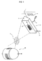
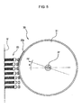
- FIG. 1 is a perspective view of a charging apparatus used with a mobile robot 30 according to an embodiment of the present invention.
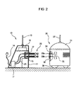
- FIG. 2 is a view showing the mobile robot 30 which approaches a charging unit 10 included in the charging apparatus of FIG. 1.
- the charging apparatus used with the mobile robot 30 according to the present invention includes the charging unit 10 and the mobile robot 30.
- the charging unit 10 includes a casing 11, a first terminal mounting board 12 provided on an outer surface of the casing 11, and a plurality of charging terminals 20 mounted thereon.
- a first antenna 13 is provided on an upper surface of the casing 11 to transceive signals with the mobile robot 30.
- the charging unit 10 includes a power cord 14 having a plug to connect the charging unit 10 to an outlet 2 which is provided on a wall 1.
- the charging terminals 20 are provided on the first terminal mounting board 12.
- the charging terminals 20 are arranged in a plurality of rows to be placed together within a predetermined range, and are movable with respect to the charging unit 10 by an external force.
- the mobile robot 30 moves to a predetermined reference position A in response to a signal which is transmitted from the charging unit 10 through the first antenna 13. Thereafter, the mobile robot 30 moves from the predetermined reference position A to the first terminal mounting board 12 so as to be in contact with the first terminal mounting board 12.
- the mobile robot 30 includes a robot body 31 and a second terminal mounting board 32 provided on an outer surface of the robot body 31.
- First and second contact terminals 33a and 33b are mounted to the second terminal mounting board 32.
- the first and second contact terminals 33a and 33b are electrically connected to a rechargeable battery 35 via an electric cable 34.
- Wheels 36 which are mounted to a bottom of the robot body 31, are driven by a wheel drive motor (not shown).
- the wheel drive motor is driven by electricity which is supplied from the rechargeable battery 35 in response to a control signal transmitted from a robot control unit (not shown).
- the control signal may be received through a second antenna 37.
- the first terminal mounting board 12 of the charging unit 10 is mounted to a position corresponding to the second terminal mounting board 32 having the first and second contact terminals 33a and 33b of the mobile robot 30.
- a guide groove 15 is arranged in upper and lower portions of the first terminal mounting board 12.
- the reference numeral 16 denotes a control circuit box in which a control circuit is installed to control an operation of the charging unit 10, including the operation of transceiving signals with the mobile robot 30.
- the reference numeral 17 denotes a charging circuit box in which a charging circuit is installed to generate a charging current using an external electricity supplied through the outlet 2 and the power cord 14, and the charging current is outputted to the charging terminals 20 through an electric cable 25.
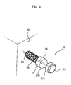
- each of the plurality of charging terminals 20 includes a body 21, a support shaft 24 to support the body 21, a restoring spring 22, and a contact plate 23.
- a groove 21b is formed on a predetermined portion of the body 21, and a head 21a extends from the groove 21b.
- the contact plate 23 is mounted on a predetermined portion of the head 21a. Because the body 21 is made of a flexible insulating material, the head 21a is movable when the external force is applied to the head 21a.
- the contact plate 23 is made of copper.
- the electric cable 25 is embedded in the support shaft 24 and the body 21, and an end of the electric cable 25 is electrically connected to the contact plate 23.
- the contact plate 23 is in surface contact with a corresponding one of the first and second contact terminals 33a and 33b of the mobile robot 30.
- a position error may occur due to obstacles disposed on a support surface between the mobile robot 30 and the charging unit 10, or friction between the wheels 36 and the support surface.
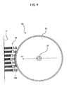
- FIG. 5 when the mobile robot 30 approaches the first terminal mounting board 12 of the charging unit 10 in a direction P2having an angle B with the straight direction P, some of the charging terminals 20, which are arranged on the upper portion of the first terminal mounting board 12, are brought into electrical contact with corresponding ones of the first contact terminals 33a provided on the upper portion of the first terminal mounting board 32. Further, although not shown in FIG.
- the mobile robot 30 can be brought into effective electrical contact with the charging unit 10.
- the charging current flows through the electric cables 25 and 34, so that the rechargeable battery 35 of the mobile robot 30 starts to be recharged.
- the mobile robot 30 retreats from the charging unit 10 to be electrically disconnected from the charging unit 10, thereby stopping the charging operation.
- Each of the charging terminals 20 according to this embodiment of the present invention is constructed so that the head 21a extends from the body 21.
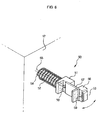
- charging terminals according to other embodiments will be described hereinafter with reference to FIGS. 6-8.
- the charging terminals according to the other embodiments have the same function as the charging terminals of FIG. 3.
- each of charging terminals 50 includes a body 51, a support shaft 54 to support the body 51, a restoring spring 52, and a contact plate 53.
- the body 51 is separated from the head 56.
- the body 51 is coupled to the head 56 by a coupling plate 57.
- the body 51 and the head 56 are insulators. Because the coupling plate 57 is made of a thin metal plate, the head 56 is movable when the external force is applied to the head 56, which is coupled to the coupling plate 57.
- the contact plate 53 is mounted on a predetermined portion of the head 56 and is made of copper.
- An electric cable 55 is embedded in the support shaft 54 and the body 51.
- An electric wire 58 of the embedded electric cable 55 is electrically connected to a first end of the coupling plate 57. Further, a second end of the coupling plate 57 is electrically connected to the contact plate 53 via a metal piece 59.
- the restoring spring 52 which is connected to the body 51 is compressed, and then the support shaft 54 enters the guide groove 15 of the first terminal mounting board 12. Meanwhile, when the contact plate 53 is released from the corresponding one of the first and second contact terminals 33a and 33b, the body 51 is returned to an original position thereof by the restoring spring 52.
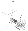
- each of charging terminals 60 includes a body 61, a support shaft 64 to support the body 61, a restoring spring 62, and a contact plate 63.
- each charging terminal 60 the body 61 is coupled to a head 66 by a metal pin 67.
- the head 66 is movable.
- the body 61 and the head 66 are insulators.
- the contact plate 63 is mounted on a predetermined portion of the head 66.
- the contact plate 63 is made of copper.
- An electric cable 65 is embedded in the support shaft 64 and the body 61.
- An electric wire 68 of the embedded electric cable 65 is electrically connected to a first end of the metal pin 67 via a bent piece 68a which is made of metal.
- a second end of the metal pin 67 is electrically connected to a metal bush 69a which is embedded in the head 66.
- the metal bush 69a is electrically connected to the contact plate 63 by a metal piece 69.
- the restoring spring 62 which is connected to the body 61 is compressed, and the support shaft 64 enters the guide groove 15 of the first terminal mounting board 12. Meanwhile, when the contact plate 63 is released from the corresponding one of the first and second contact terminals 33a and 33b, the body 61 is returned to an original position thereof by the restoring spring 62.
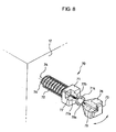
- each of charging terminals 70 includes a body 71, a support shaft 74 to support the body 71, a restoring spring 72, and a contact plate 73.
- the body 71 is coupled to a head 76 by a coupling rod 78.
- the coupling rod 78 is made of metal, and has a ball 78a at one end thereof.
- the coupling rod 78 is fastened to the head 76 through a screw-type fastening method.
- a socket 71a is provided at a position of the body 71, and the ball 78a is rotatably set in the socket 71a.
- the head 76 is movable.
- the body 71 and the head 76 are insulators.
- the contact plate 73 is mounted to a predetermined portion of the head 76 and is made of copper.
- An electric cable 75 is embedded in the support shaft 74 and the body 71.
- An electric wire 77 of the embedded electric cable 75 is electrically connected to a conductive spring 77a and a metal piece 77b.
- the conductive spring 77a makes the metal piece 77b be in close contact with the ball 78a.
- the metal piece 77b is electrically connected to the contact plate 73 via the coupling rod 78.
- the restoring spring 72 which is connected to the body 71 is compressed, and the support shaft 74 enters the guide groove 15 of the terminal mounting board 12. Meanwhile, when the contact plate 73 is released from the corresponding one of the first and second contact terminals 33a and 33b, the body 71 is returned to an original position thereof by the restoring spring 72.
- the present invention provides a charging apparatus used with a mobile robot, which is constructed such that a plurality of charging terminals are arranged on predetermined portions of a charging unit, and each head of the charging terminals is movable, thus allowing the mobile robot to be easily and rapidly brought into electrical contact with the charging unit. Further, the charging apparatus used with the mobile robot, according to the embodiments of the present invention, does not need an expensive guide unit to prevent a charging failure, thereby reducing manufacturing costs.
Landscapes
- Engineering & Computer Science (AREA)
- Mechanical Engineering (AREA)
- Power Engineering (AREA)
- Transportation (AREA)
- Robotics (AREA)
- Manufacturing & Machinery (AREA)
- Charge And Discharge Circuits For Batteries Or The Like (AREA)
- Manipulator (AREA)
- Electric Propulsion And Braking For Vehicles (AREA)
- Control Of Position, Course, Altitude, Or Attitude Of Moving Bodies (AREA)
Abstract

Description
In still another aspect of this embodiment, the coupling unit may be a metal plate, a metal pin, or a coupling rod which has a ball at an end thereof.
The
The first
When at least one charging
Because the
An
Claims (30)
- A charging apparatus used with a mobile robot (30), comprising:a rechargeable battery (35) and a contact terminal (33a/b) included in the mobile robot (30); anda charging unit (10) including a plurality of charging terminals (20/50/60/70) at least one of which is brought into electrical contact with the contact terminal (33a/b) of the mobile robot (30) to supply a charging current to the rechargeable battery (35) of the mobile robot (30), each of the charging terminals (20/50/60/70) comprising,
a body (21), and
a head (21a) movably coupled to the body (21),and having a contact plate (23) mounted on a predetermined portion of the head (21a) to be brought into electrical contact with the contact terminal (33a/b) of the mobile robot (30). - The charging apparatus according to claim 1, wherein the plurality of charging terminals (20) are arranged in a plurality of rows.
- The charging apparatus according to claim 1 or claim 2, wherein each of the charging terminals (20) further comprises:a support shaft (24) to support the body (21); andan elastic member (22) to restore the body (21) to an original position thereof.
- The charging apparatus according to any preceding claim, wherein the body (21) comprises a groove (21b), and the head (21a) extends from the groove (21b) to be integrated with the body (21) in a single structure.
- The charging apparatus according to any preceding claim, wherein the charging unit (10) comprises an electrical cable (14) coupled to an external power source, and each of the charging terminals (20/50/60/70) comprises an electrical connecting member (25) embedded in the body (21) and the head (21a) to electrically connect the contact plate (23) to the electrical cable (14).
- The charging apparatus according to any preceding claim, wherein each of the charging terminals (50/60/70) comprises a coupling unit (56/67) to couple the body (21) to the head (21a).
- The charging apparatus according to claim 6, wherein the coupling unit comprises a metal plate (57).
- The charging apparatus according to claim 6 or claim 7, wherein the coupling unit comprises a metal pin (59).
- The charging apparatus according to claim 6, claim 7 or claim 8, wherein the coupling unit comprises a coupling rod (78) which has a ball (78a) at an end thereof.
- A charging apparatus used with a mobile robot (30) having a rechargeable battery (35) and a contact terminal (33a/b), comprising:a casing (11);a terminal mounting board (12) disposed on the casing (11);a charging circuit connectable to an external power source;a guide groove (15) formed on the terminal mounting board (12); anda charging terminal (60) comprising,
a body having a first support member (64) to be inserted into the guide groove (15), and having a second support member (61) extending from the first support member (64) to protrude from the terminal mounting board (12), anda head (66) movably coupled to the second support member (61) of the body, and having a contact plate (63) mounted on a portion of the head (66) and electrically connected to the charging circuit. - The charging apparatus according to claim 10, wherein the charging terminal (60) further comprises:a groove portion formed on the second support member (61) between the portion of the head (66) and the first support member (64).
- The charging apparatus according to claim 11, wherein the first support member (64) moves in a direction parallel to the guide groove (15), and the groove portion of the second support member (61) has an area perpendicular to the direction parallel to the guide groove (15), the area being smaller than at least one of an area of the portion of the head (66) and an area of the second support member (61).
- The charging apparatus according to claim 12, wherein the area of the groove portion of the second support member (61) is smaller than an area of the first support member (64).
- The charging apparatus according to claim 10, wherein the charging terminal (60) further comprises:an elastic member (62) disposed between the terminal mounting board (12) and the body of the charging terminal (60) so that the first support member (64) slides along the guide groove (15) of the terminal mounting board (12).
- The charging apparatus according to any one of claims 10 to 14, wherein the first support member (65/24), the second support member (61/21), and the head (66/21a) are formed in a monolithic single body.
- The charging apparatus according to any one of claims 10 to 15, wherein the body comprises:a through hole formed to pass through the body from the first support member (64) to the portion of the head (66); andan electrical cable (65) disposed in the through hole to be electrically connected to the contact plate (63) and the power source.
- The charging apparatus according to any one of claims 10 to 16, wherein the first support member (64) of the body moves in a first direction while the head (66) moves in a second direction.
- The charging apparatus according to any one of claims 10 to 17, wherein the first support member (64) moves in a first direction along the guide groove (15), and the head (66) moves in a second direction different from the first direction when the contact terminal (33a/b) of the robot (30) moves toward the contact plate (63) in a third direction different from the first and second directions.
- The charging apparatus according to any one of claims 10 to 18, wherein the first support member (64) of the body and the head (66) moves in different directions with respect to the terminal mounting board (12) and the body, respectively, when the contact terminal (33a/b) of the robot (30) is not disposed on a line passing through the guide groove (15) and a center of the robot (30).
- The charging apparatus according to any one of claims 10 to 19, wherein the charging terminal (60) comprises:a coupling member (67) coupled between the second support member (61) of the body and the head (66) so that the head (66) elastically moves with respect to the body.
- The charging apparatus according to claim 20, wherein the charging terminal (60) further comprises:a through hole formed to pass through the first and second support members (65/61) of the body;an electrical cable (65) disposed in the through hole to be electrically connected to the coupling member (67) and the power source; andanother electrical cable (69) connecting the contact plate and the coupling member (67).
- The charging apparatus according to any one of claims 10 to 21, wherein the charging terminal (60) comprises:a pin (67) coupled between the second support member (61) of the body and the head (66) so that the head (66) can move with respect to the second support member (61), andelectrically connected between the power source and the contact plate (63).
- The charging apparatus according to claim 22, wherein the charging terminal (60) comprises:a through hole formed to pass through the body from the first support member (64) to a portion of the second support member (61);an electrical cable (65) disposed in the through hole to be electrically connected to the charging circuit;an electric cable (68) disposed on the second support member (61) to connect the electric cable (65) to the pin (67); anda piece (69a) disposed on the head (66) to connect the pin (67) to the contact plate (63).
- The charging apparatus according to any one of claims 10 to 23, wherein the charging terminal (70) comprises:a socket formed (71a) on the second support member (71); anda ball (78a) rotatably disposed in the socket (71a) and formed on the head (76).
- The charging apparatus according to claim 24, wherein the charging terminal (70) comprises:a through hole formed to pass through the body from the first support member (74) to a portion of the second support member (71);an electrical cable (75) disposed in the through hole to be electrically connected to the charging circuit and the contact plate (73); anda conductive wire (77) electrically connecting the electrical cable (75) to the contact plate (73) through the ball (78a).
- The charging apparatus according to claim 25, wherein the electrical wire (77) comprises:a metal piece (77a) disposed on the second support member (71) to be connected to the electrical cable (75); anda coupling rod (78) disposed in the head (76) to be electrically connected between the metal piece (77a) and the contact plate (73).
- The charging apparatus according to claim 25, wherein the electrical wire (77) comprises a hole formed in the ball (78a) such that the conductive wire (78) passes through the hole to be electrically connected to the contact plate (73).
- A charging apparatus used with a mobile robot (30), comprising:a rechargeable battery (35) and a plurality of contact terminals (33a/b) included in the mobile robot (30); anda charging unit (10) including a plurality of charging terminals (20) disposed to contact corresponding ones of the contact terminals (33a/b) to supply a charging current to the rechargeable battery (35) of the mobile robot (30), each of the charging terminals (20) comprising,
a body (21) having a conductive material electrically connected to an external power source, and
a head (21a) movably coupled to the body (21), and having a contact plate (23) mounted on a predetermined portion of the head (21) and electrically connected to the conductive material to be brought into electrical contact with a corresponding one of the contact terminals (33a/b) of the mobile robot (30). - The charging apparatus according to claim 29, wherein respective heads (21a) of the charging terminals (20) are bent with respect to corresponding ones of bodies (21) of the charging terminals (20) in different directions when the contact terminals (33a/b) of the mobile robot (30) contact corresponding ones of the charging terminals (20) of the charging unit (10) in a direction having an angle with a direction disposed on a line passing through a center of the mobile robot (30) and a center portion of the charging terminals (20).
- The charging apparatus according to claim 29, wherein the contact terminals (33a/b) are disposed in a circular direction about a center of the mobile robot (30), the charging terminals (20) comprise first and second charging terminals having a first body with a first head and a second body with a second head, respectively, the first head of the first charging terminal being disposed on a line having a first distance with a center thereof passing through the center of the mobile robot and a center portion of the charging terminals (20) moves in a first direction with respect to the first body of the first charging terminal, and the second head of the second charging terminal being disposed on a line having a second distance with a center thereof passing through the center of the mobile robot and a center portion of the charging terminals (20) moves in a second direction with respect to the second body of the second charging terminal.
Applications Claiming Priority (2)
| Application Number | Priority Date | Filing Date | Title |
|---|---|---|---|
| KR1020030073327A KR100820743B1 (en) | 2003-10-21 | 2003-10-21 | Charging device of mobile robot |
| KR2003073327 | 2003-10-21 |
Publications (3)
| Publication Number | Publication Date |
|---|---|
| EP1526626A2 true EP1526626A2 (en) | 2005-04-27 |
| EP1526626A3 EP1526626A3 (en) | 2007-11-21 |
| EP1526626B1 EP1526626B1 (en) | 2011-04-13 |
Family
ID=34386787
Family Applications (1)
| Application Number | Title | Priority Date | Filing Date |
|---|---|---|---|
| EP04250159A Expired - Lifetime EP1526626B1 (en) | 2003-10-21 | 2004-01-14 | Charging apparatus for use with a mobile robot |
Country Status (6)
| Country | Link |
|---|---|
| US (1) | US7227334B2 (en) |
| EP (1) | EP1526626B1 (en) |
| JP (1) | JP3844473B2 (en) |
| KR (1) | KR100820743B1 (en) |
| CN (1) | CN100395937C (en) |
| DE (1) | DE602004032201D1 (en) |
Cited By (7)
| Publication number | Priority date | Publication date | Assignee | Title |
|---|---|---|---|---|
| CN101416391B (en) * | 2006-03-31 | 2011-04-06 | Nxp股份有限公司 | Method and system for a signal driver using capacitive feedback |
| WO2011145989A1 (en) * | 2010-05-19 | 2011-11-24 | Husqvarna Ab | Effective charging by multiple contact points |
| EP2151020A4 (en) * | 2007-05-25 | 2014-05-07 | Joergen Olsson | Cordless electrical connection with simple key |
| CN106025628A (en) * | 2016-06-02 | 2016-10-12 | 江苏省冶金设计院有限公司 | Electric adaptive electrical junction box apparatus used for mobile charging bucket, and dual-charging-bucket electric flat car |
| WO2018125383A1 (en) * | 2016-12-29 | 2018-07-05 | Intel Corporation | Robots and apparatus, systems and methods for powering robots |
| WO2018184674A1 (en) * | 2017-04-05 | 2018-10-11 | Schunk Bahn- Und Industrietechnik Gmbh | Contact unit for a battery electric vehicle |
| CN109606159A (en) * | 2018-12-18 | 2019-04-12 | 南京理工大学 | A portable mobile charging device suitable for AGV logistics trolley |
Families Citing this family (109)
| Publication number | Priority date | Publication date | Assignee | Title |
|---|---|---|---|---|
| US20040162637A1 (en) | 2002-07-25 | 2004-08-19 | Yulun Wang | Medical tele-robotic system with a master remote station with an arbitrator |
| US6925357B2 (en) | 2002-07-25 | 2005-08-02 | Intouch Health, Inc. | Medical tele-robotic system |
| US7813836B2 (en) | 2003-12-09 | 2010-10-12 | Intouch Technologies, Inc. | Protocol for a remotely controlled videoconferencing robot |
| US20050204438A1 (en) | 2004-02-26 | 2005-09-15 | Yulun Wang | Graphical interface for a remote presence system |
| KR100548895B1 (en) * | 2004-05-17 | 2006-02-02 | 삼성광주전자 주식회사 | Filling device for robot vacuum cleaner |
| US8077963B2 (en) | 2004-07-13 | 2011-12-13 | Yulun Wang | Mobile robot with a head-based movement mapping scheme |
| JP2006095007A (en) * | 2004-09-29 | 2006-04-13 | Funai Electric Co Ltd | Charging type moving system |
| US9198728B2 (en) | 2005-09-30 | 2015-12-01 | Intouch Technologies, Inc. | Multi-camera mobile teleconferencing platform |
| US8849679B2 (en) | 2006-06-15 | 2014-09-30 | Intouch Technologies, Inc. | Remote controlled robot system that provides medical images |
| KR100847771B1 (en) * | 2006-10-25 | 2008-07-23 | 엘지전자 주식회사 | Mobile robot charging device and charging method |
| KR100765847B1 (en) | 2006-12-26 | 2007-10-10 | (주)다사로봇 | Charging Station with Caster Guide |
| JP4893887B2 (en) * | 2007-04-02 | 2012-03-07 | 本田技研工業株式会社 | Charger |
| US9160783B2 (en) | 2007-05-09 | 2015-10-13 | Intouch Technologies, Inc. | Robot system that operates through a network firewall |
| JP4590644B2 (en) * | 2007-12-06 | 2010-12-01 | 本田技研工業株式会社 | Mobile robot charging device |
| US10875182B2 (en) | 2008-03-20 | 2020-12-29 | Teladoc Health, Inc. | Remote presence system mounted to operating room hardware |
| US8179418B2 (en) | 2008-04-14 | 2012-05-15 | Intouch Technologies, Inc. | Robotic based health care system |
| US8170241B2 (en) | 2008-04-17 | 2012-05-01 | Intouch Technologies, Inc. | Mobile tele-presence system with a microphone system |
| CN101615703A (en) * | 2008-06-26 | 2009-12-30 | 鸿富锦精密工业(深圳)有限公司 | Charging device |
| US9193065B2 (en) * | 2008-07-10 | 2015-11-24 | Intouch Technologies, Inc. | Docking system for a tele-presence robot |
| US9842192B2 (en) | 2008-07-11 | 2017-12-12 | Intouch Technologies, Inc. | Tele-presence robot system with multi-cast features |
| US8340819B2 (en) | 2008-09-18 | 2012-12-25 | Intouch Technologies, Inc. | Mobile videoconferencing robot system with network adaptive driving |
| US8996165B2 (en) | 2008-10-21 | 2015-03-31 | Intouch Technologies, Inc. | Telepresence robot with a camera boom |
| US8463435B2 (en) | 2008-11-25 | 2013-06-11 | Intouch Technologies, Inc. | Server connectivity control for tele-presence robot |
| US9138891B2 (en) * | 2008-11-25 | 2015-09-22 | Intouch Technologies, Inc. | Server connectivity control for tele-presence robot |
| US8849680B2 (en) | 2009-01-29 | 2014-09-30 | Intouch Technologies, Inc. | Documentation through a remote presence robot |
| US8897920B2 (en) | 2009-04-17 | 2014-11-25 | Intouch Technologies, Inc. | Tele-presence robot system with software modularity, projector and laser pointer |
| DE102009032103A1 (en) * | 2009-07-08 | 2011-01-13 | Jungheinrich Aktiengesellschaft | Power unit for an engine of a truck |
| US11399153B2 (en) * | 2009-08-26 | 2022-07-26 | Teladoc Health, Inc. | Portable telepresence apparatus |
| US8384755B2 (en) | 2009-08-26 | 2013-02-26 | Intouch Technologies, Inc. | Portable remote presence robot |
| TWM377001U (en) * | 2009-10-16 | 2010-03-21 | Micro Star Int Co Ltd | Electronic device |
| US8212533B2 (en) * | 2009-12-23 | 2012-07-03 | Toyota Motor Engineering & Manufacturing North America, Inc. | Robot battery charging apparatuses and methods |
| US11154981B2 (en) * | 2010-02-04 | 2021-10-26 | Teladoc Health, Inc. | Robot user interface for telepresence robot system |
| US8670017B2 (en) | 2010-03-04 | 2014-03-11 | Intouch Technologies, Inc. | Remote presence system including a cart that supports a robot face and an overhead camera |
| US10343283B2 (en) | 2010-05-24 | 2019-07-09 | Intouch Technologies, Inc. | Telepresence robot system that can be accessed by a cellular phone |
| US10808882B2 (en) | 2010-05-26 | 2020-10-20 | Intouch Technologies, Inc. | Tele-robotic system with a robot face placed on a chair |
| KR101259822B1 (en) * | 2010-11-12 | 2013-04-30 | 삼성중공업 주식회사 | Moving appratus and method of working in hull block |
| US9264664B2 (en) | 2010-12-03 | 2016-02-16 | Intouch Technologies, Inc. | Systems and methods for dynamic bandwidth allocation |
| US9082112B2 (en) | 2010-12-15 | 2015-07-14 | Symbotic, LLC | Autonomous transport vehicle charging system |
| US12093036B2 (en) | 2011-01-21 | 2024-09-17 | Teladoc Health, Inc. | Telerobotic system with a dual application screen presentation |
| CN104898652B (en) | 2011-01-28 | 2018-03-13 | 英塔茨科技公司 | Mutually exchanged with a moveable tele-robotic |
| US9323250B2 (en) | 2011-01-28 | 2016-04-26 | Intouch Technologies, Inc. | Time-dependent navigation of telepresence robots |
| US11482326B2 (en) | 2011-02-16 | 2022-10-25 | Teladog Health, Inc. | Systems and methods for network-based counseling |
| US10769739B2 (en) | 2011-04-25 | 2020-09-08 | Intouch Technologies, Inc. | Systems and methods for management of information among medical providers and facilities |
| TW201245931A (en) * | 2011-05-09 | 2012-11-16 | Asustek Comp Inc | Robotic device |
| US20140139616A1 (en) | 2012-01-27 | 2014-05-22 | Intouch Technologies, Inc. | Enhanced Diagnostics for a Telepresence Robot |
| US9098611B2 (en) | 2012-11-26 | 2015-08-04 | Intouch Technologies, Inc. | Enhanced video interaction for a user interface of a telepresence network |
| US8836751B2 (en) | 2011-11-08 | 2014-09-16 | Intouch Technologies, Inc. | Tele-presence system with a user interface that displays different communication links |
| US11093722B2 (en) | 2011-12-05 | 2021-08-17 | Adasa Inc. | Holonomic RFID reader |
| US10846497B2 (en) | 2011-12-05 | 2020-11-24 | Adasa Inc. | Holonomic RFID reader |
| US9251313B2 (en) | 2012-04-11 | 2016-02-02 | Intouch Technologies, Inc. | Systems and methods for visualizing and managing telepresence devices in healthcare networks |
| US8902278B2 (en) | 2012-04-11 | 2014-12-02 | Intouch Technologies, Inc. | Systems and methods for visualizing and managing telepresence devices in healthcare networks |
| WO2013176762A1 (en) | 2012-05-22 | 2013-11-28 | Intouch Technologies, Inc. | Social behavior rules for a medical telepresence robot |
| US9361021B2 (en) | 2012-05-22 | 2016-06-07 | Irobot Corporation | Graphical user interfaces including touchpad driving interfaces for telemedicine devices |
| USD722281S1 (en) * | 2012-07-09 | 2015-02-10 | Adept Technology, Inc. | Mobile robotic platform |
| JP5998776B2 (en) * | 2012-09-12 | 2016-09-28 | セイコーエプソン株式会社 | Robot and robot system |
| US9124013B2 (en) * | 2012-10-16 | 2015-09-01 | Covidien Lp | Electrical contact pins for electrically coupling electronic devices, batteries, and/or battery chargers |
| RU2523420C1 (en) * | 2013-01-09 | 2014-07-20 | Федеральное государственное бюджетное образовательное учреждение высшего профессионального образования "Уфимский государственный авиационный технический университет" | Recharger system for batteries of electric drones |
| US9469208B2 (en) * | 2013-03-15 | 2016-10-18 | Symbotic, LLC | Rover charging system |
| CN104042164A (en) * | 2013-03-14 | 2014-09-17 | 杭州五星电子有限公司 | Control assembly of intelligent dust collector |
| JP6115502B2 (en) * | 2014-03-24 | 2017-04-19 | トヨタ自動車株式会社 | Charger |
| FR3021914B1 (en) * | 2014-06-05 | 2018-02-23 | Aldebaran Robotics | BASE FOR RECHARGING A BATTERY AND METHOD FOR CHARGING USING SUCH A BASE |
| DE102014212427A1 (en) * | 2014-06-27 | 2016-01-14 | Robert Bosch Gmbh | Service robot system |
| DK3047783T3 (en) * | 2015-01-20 | 2017-10-23 | Eurofilters Holding Nv | VACUUM CLEANER ROBOT |
| USD760649S1 (en) | 2015-06-22 | 2016-07-05 | Mtd Products Inc | Docking station |
| CN106655302B (en) * | 2015-10-29 | 2023-06-20 | 深圳市朗驰欣创科技股份有限公司 | Charging device and charging method based on same |
| DE112017001029T5 (en) * | 2016-02-29 | 2018-12-27 | Lg Electronics Inc. | vacuum cleaner |
| CN107198499B (en) * | 2016-03-18 | 2021-03-05 | 松下电器(美国)知识产权公司 | Autonomous moving apparatus, autonomous moving method, and autonomous moving system |
| US11172605B2 (en) | 2016-06-30 | 2021-11-16 | Tti (Macao Commercial Offshore) Limited | Autonomous lawn mower and a system for navigating thereof |
| CN107666160A (en) * | 2016-07-29 | 2018-02-06 | 鸿富锦精密电子(天津)有限公司 | Charging device and the charge control system with the charging device |
| US10404084B2 (en) * | 2016-10-08 | 2019-09-03 | Zhejiang Guozi Robot Technology Co., Ltd. | Self-charging device for mobile robots |
| FR3059479B1 (en) * | 2016-11-28 | 2019-03-15 | Commissariat A L'energie Atomique Et Aux Energies Alternatives | SECURE ELECTRICAL CONNECTION SYSTEM |
| JP6498225B2 (en) * | 2017-02-03 | 2019-04-10 | 株式会社熊平製作所 | Safe deposit system |
| US11862302B2 (en) | 2017-04-24 | 2024-01-02 | Teladoc Health, Inc. | Automated transcription and documentation of tele-health encounters |
| CN106953202B (en) * | 2017-05-05 | 2023-10-17 | 上海诺亚木木机器人科技有限公司 | A charging connector and charging equipment |
| CN109256820A (en) * | 2017-07-12 | 2019-01-22 | 先进机器人有限公司 | terminal charging seat with active optical guiding mechanism and electric shock protection |
| US10483007B2 (en) | 2017-07-25 | 2019-11-19 | Intouch Technologies, Inc. | Modular telehealth cart with thermal imaging and touch screen user interface |
| US11636944B2 (en) | 2017-08-25 | 2023-04-25 | Teladoc Health, Inc. | Connectivity infrastructure for a telehealth platform |
| CN107443423B (en) * | 2017-09-06 | 2018-08-17 | 泰州市永欣金属有限公司 | A kind of intelligent robot equipment |
| CN107933367B (en) * | 2017-12-19 | 2023-09-26 | 库卡机器人(广东)有限公司 | Charging device for unmanned carrier and unmanned carrier with charging device |
| KR102375435B1 (en) * | 2018-03-28 | 2022-03-18 | 한국전자기술연구원 | Charging module structure supporting automatic charging and charging system comprising the same |
| EP3552860A1 (en) * | 2018-04-10 | 2019-10-16 | Hager-Electro Sas | Charger plug and charging receiver |
| US10617299B2 (en) | 2018-04-27 | 2020-04-14 | Intouch Technologies, Inc. | Telehealth cart that supports a removable tablet with seamless audio/video switching |
| CN108551045B (en) * | 2018-06-07 | 2019-05-03 | 斯坦德机器人(深圳)有限公司 | A multi-degree-of-freedom charging pile mechanism |
| CN108832397B (en) * | 2018-06-15 | 2024-06-28 | 浙江国自机器人技术有限公司 | Mobile robot and mobile robot charging mechanism |
| KR102137164B1 (en) * | 2018-06-15 | 2020-07-24 | 엘지전자 주식회사 | Guidance robot |
| CN109100745B (en) * | 2018-08-22 | 2020-08-07 | 江苏省江都水利工程管理处 | Automatic system of patrolling and examining of water conservancy pump station |
| US11658444B2 (en) * | 2018-10-12 | 2023-05-23 | Riyad K. Elagha | Retractable protective sleeve for portable charging cable |
| JP7444460B2 (en) * | 2018-12-03 | 2024-03-06 | Groove X株式会社 | charging station for robots |
| CN110429686A (en) * | 2019-08-26 | 2019-11-08 | 深圳蓝胖子机器人有限公司 | Automatic charging device and plug-in charging male head assembly |
| USD965656S1 (en) | 2019-10-14 | 2022-10-04 | Omron Corporation | Mobile robot |
| CN111619389B (en) * | 2020-05-19 | 2021-11-30 | 海通科创(深圳)有限公司 | Mobile charging method for electric vehicle, mobile charging device and storage medium |
| KR102462702B1 (en) * | 2020-11-13 | 2022-11-04 | 현대무벡스 주식회사 | Tiltable terminal unit for charging |
| KR102462703B1 (en) * | 2020-11-13 | 2022-11-04 | 현대무벡스 주식회사 | Movable terminal unit for charging |
| US12296694B2 (en) | 2021-03-10 | 2025-05-13 | Techtronic Cordless Gp | Lawnmowers |
| USD1032509S1 (en) | 2021-04-23 | 2024-06-25 | Mtd Products Inc | Docking station |
| CN113437577B (en) * | 2021-06-07 | 2022-07-05 | 北京京东乾石科技有限公司 | Charging plug assembly, adaptive docking mechanism and charging pile |
| CN115474872A (en) * | 2021-06-15 | 2022-12-16 | 深圳银星智能集团股份有限公司 | Maintenance stations and cleaning systems |
| CN115733197A (en) * | 2021-08-31 | 2023-03-03 | 富泰京精密电子(烟台)有限公司 | Charging pile and charging equipment |
| US12443180B2 (en) | 2021-11-10 | 2025-10-14 | Techtronic Cordless Gp | Robotic lawn mowers |
| CN114193469B (en) * | 2021-12-10 | 2024-01-02 | 深圳供电局有限公司 | A kind of power grid operation supervision robot |
| KR102386669B1 (en) * | 2021-12-23 | 2022-04-14 | (주)시스콘 | CONTACT MODULE THAT COMPLEMENTS THE CHARGING DOCKING OF Autonomous Mobile Robot |
| AU2023200381A1 (en) | 2022-01-31 | 2023-08-17 | Techtronic Cordless Gp | Robotic garden tool |
| EP4270138A1 (en) | 2022-04-28 | 2023-11-01 | Techtronic Cordless GP | Creation of a virtual boundary for a robotic garden tool |
| CN114944564A (en) * | 2022-05-17 | 2022-08-26 | 深圳创动科技有限公司 | Robot and charging system |
| US12472611B2 (en) | 2022-05-31 | 2025-11-18 | Techtronic Cordless Gp | Peg driver |
| AU2023204696A1 (en) | 2022-07-19 | 2024-02-08 | Techtronic Cordless Gp | Display for controlling robotic tool |
| AU2023206123A1 (en) | 2022-07-29 | 2024-02-15 | Techtronic Cordless Gp | Generation of a cryptography key for a robotic garden tool |
| SE547518C2 (en) * | 2024-02-06 | 2025-10-07 | Husqvarna Ab | Robotic Work Tool Charging Device and Robotic Work Tool System |
| CN118249162B (en) * | 2024-05-27 | 2024-07-30 | 郴州市东塘电气设备有限公司 | Wire harness terminal plugging device of energy storage power distribution cabinet |
Family Cites Families (20)
| Publication number | Priority date | Publication date | Assignee | Title |
|---|---|---|---|---|
| US4822296A (en) * | 1987-06-19 | 1989-04-18 | Anton/Bauer, Inc. | Electrical connection for battery charging apparatus or the like |
| JPH0437740Y2 (en) * | 1987-07-31 | 1992-09-04 | ||
| JP2836172B2 (en) * | 1990-03-27 | 1998-12-14 | 神鋼電機株式会社 | Automatic charging device |
| JP3118268B2 (en) * | 1991-02-28 | 2000-12-18 | 三洋電機株式会社 | Automatic guided vehicle charging device |
| JPH0614408A (en) * | 1992-06-19 | 1994-01-21 | Toyota Autom Loom Works Ltd | Charger for electric motor vehicle |
| JP3309864B2 (en) * | 1992-09-29 | 2002-07-29 | 株式会社ダイフク | Battery charger for mobile vehicles |
| JP3208891B2 (en) * | 1993-02-09 | 2001-09-17 | 株式会社豊田自動織機製作所 | Automatic charging device |
| JP2833409B2 (en) * | 1993-04-26 | 1998-12-09 | 日立電線株式会社 | Contact current supply device for battery charging on mobile vehicles |
| JP3647890B2 (en) * | 1993-08-31 | 2005-05-18 | 株式会社セガ | Running body self-running system |
| US5646494A (en) | 1994-03-29 | 1997-07-08 | Samsung Electronics Co., Ltd. | Charge induction apparatus of robot cleaner and method thereof |
| JP3231546B2 (en) * | 1994-06-28 | 2001-11-26 | 株式会社東芝 | Automatic power supply system for moving objects |
| US5995884A (en) * | 1997-03-07 | 1999-11-30 | Allen; Timothy P. | Computer peripheral floor cleaning system and navigation method |
| SE523080C2 (en) * | 1998-01-08 | 2004-03-23 | Electrolux Ab | Docking system for self-propelled work tools |
| JP2000326271A (en) * | 1999-05-21 | 2000-11-28 | Denso Corp | Mobile robot |
| JP3988333B2 (en) * | 1999-09-09 | 2007-10-10 | 株式会社デンソー | Charging electrode structure of mobile robot |
| JP4228536B2 (en) * | 2000-03-28 | 2009-02-25 | 株式会社デンソー | Mobile robot |
| JP2002268746A (en) * | 2001-03-12 | 2002-09-20 | Canon Inc | Mobile robot apparatus, self-charging method for mobile robot apparatus, and medium providing control program |
| AU767561B2 (en) | 2001-04-18 | 2003-11-13 | Samsung Kwangju Electronics Co., Ltd. | Robot cleaner, system employing the same and method for reconnecting to external recharging device |
| JP2002370182A (en) | 2001-06-13 | 2002-12-24 | Matsushita Electric Ind Co Ltd | Self-propelled clean stocker robot system and its robot |
| FR2828589B1 (en) | 2001-08-07 | 2003-12-05 | France Telecom | ELECTRIC CONNECTION SYSTEM BETWEEN A VEHICLE AND A CHARGING STATION OR THE LIKE |
-
2003
- 2003-10-21 KR KR1020030073327A patent/KR100820743B1/en not_active Expired - Fee Related
-
2004
- 2004-01-02 US US10/749,394 patent/US7227334B2/en not_active Expired - Fee Related
- 2004-01-07 CN CNB2004100013582A patent/CN100395937C/en not_active Expired - Fee Related
- 2004-01-14 EP EP04250159A patent/EP1526626B1/en not_active Expired - Lifetime
- 2004-01-14 DE DE602004032201T patent/DE602004032201D1/en not_active Expired - Lifetime
- 2004-01-23 JP JP2004016195A patent/JP3844473B2/en not_active Expired - Fee Related
Cited By (13)
| Publication number | Priority date | Publication date | Assignee | Title |
|---|---|---|---|---|
| CN101416391B (en) * | 2006-03-31 | 2011-04-06 | Nxp股份有限公司 | Method and system for a signal driver using capacitive feedback |
| EP2151020A4 (en) * | 2007-05-25 | 2014-05-07 | Joergen Olsson | Cordless electrical connection with simple key |
| WO2011145989A1 (en) * | 2010-05-19 | 2011-11-24 | Husqvarna Ab | Effective charging by multiple contact points |
| US9419453B2 (en) | 2010-05-19 | 2016-08-16 | Husqvarna Ab | Effective charging by multiple contact points |
| CN106025628A (en) * | 2016-06-02 | 2016-10-12 | 江苏省冶金设计院有限公司 | Electric adaptive electrical junction box apparatus used for mobile charging bucket, and dual-charging-bucket electric flat car |
| US10377252B2 (en) | 2016-12-29 | 2019-08-13 | Intel Corporation | Robots and apparatus, systems and methods for powering robots |
| WO2018125383A1 (en) * | 2016-12-29 | 2018-07-05 | Intel Corporation | Robots and apparatus, systems and methods for powering robots |
| US11059375B2 (en) | 2016-12-29 | 2021-07-13 | Intel Corporation | Robots and apparatus, systems and methods for powering robots |
| WO2018184674A1 (en) * | 2017-04-05 | 2018-10-11 | Schunk Bahn- Und Industrietechnik Gmbh | Contact unit for a battery electric vehicle |
| RU2739530C1 (en) * | 2017-04-05 | 2020-12-25 | Шунк Транзит Системз Гмбх | Contact unit for vehicle operating on electric battery |
| US11186189B2 (en) | 2017-04-05 | 2021-11-30 | Schunk Transit Systems Gmbh | Contact unit for a battery electric vehicle |
| CN109606159A (en) * | 2018-12-18 | 2019-04-12 | 南京理工大学 | A portable mobile charging device suitable for AGV logistics trolley |
| CN109606159B (en) * | 2018-12-18 | 2022-04-01 | 南京理工大学 | Portable portable charging device suitable for AGV commodity circulation dolly |
Also Published As
| Publication number | Publication date |
|---|---|
| KR100820743B1 (en) | 2008-04-10 |
| EP1526626B1 (en) | 2011-04-13 |
| US20050083011A1 (en) | 2005-04-21 |
| JP2005130687A (en) | 2005-05-19 |
| KR20050038114A (en) | 2005-04-27 |
| CN100395937C (en) | 2008-06-18 |
| EP1526626A3 (en) | 2007-11-21 |
| DE602004032201D1 (en) | 2011-05-26 |
| CN1610208A (en) | 2005-04-27 |
| US7227334B2 (en) | 2007-06-05 |
| JP3844473B2 (en) | 2006-11-15 |
Similar Documents
| Publication | Publication Date | Title |
|---|---|---|
| EP1526626B1 (en) | Charging apparatus for use with a mobile robot | |
| US6312271B1 (en) | Connector having foldable plug | |
| US20100026239A1 (en) | Charging system and charging apparatus thereof | |
| US5869947A (en) | Rechargeable hand held vacuum cleaner with electrical connections circuit board with spring contacts | |
| EP0788703A1 (en) | Radio-telephone cradle connector | |
| US6840813B2 (en) | Connecting apparatus for three phase induction motor of electric vehicle | |
| CN1230846C (en) | Forward/backward circuit for DPDT type switch | |
| JP3231546B2 (en) | Automatic power supply system for moving objects | |
| WO2007142487A1 (en) | External battery structure for robot cleaner | |
| US6458002B1 (en) | Rear wiper hatch cassette using interlocking parts | |
| EP4297990A1 (en) | Docking assembly for an electronic device | |
| CN217824321U (en) | Charging stand and charging base station | |
| KR20210009235A (en) | Joint connector for vehicle | |
| CN107819257B (en) | Electric connector and motor with same | |
| JP2001273945A (en) | External power supply connecting structure of mobile robot | |
| JP2001145212A (en) | Battery device for electric vehicles | |
| CN217334421U (en) | Electrostatic discharge structure, charging connection mechanism, power supply connection mechanism and transport vehicle | |
| US7122274B2 (en) | Receptacle for battery-using equipment | |
| CN222885123U (en) | Autonomous mobile device | |
| CN220984994U (en) | Magnetic connector and electronic equipment with same | |
| CN214589512U (en) | Electric connector and scooter | |
| CN113473842A (en) | Battery placement with sensor | |
| CN223884983U (en) | Base station and power supply unit | |
| KR102386669B1 (en) | CONTACT MODULE THAT COMPLEMENTS THE CHARGING DOCKING OF Autonomous Mobile Robot | |
| CN222601489U (en) | Plug electric connector, socket electric connector and electric connector combination |
Legal Events
| Date | Code | Title | Description |
|---|---|---|---|
| PUAI | Public reference made under article 153(3) epc to a published international application that has entered the european phase |
Free format text: ORIGINAL CODE: 0009012 |
|
| AK | Designated contracting states |
Kind code of ref document: A2 Designated state(s): AT BE BG CH CY CZ DE DK EE ES FI FR GB GR HU IE IT LI LU MC NL PT RO SE SI SK TR |
|
| AX | Request for extension of the european patent |
Extension state: AL LT LV MK |
|
| PUAL | Search report despatched |
Free format text: ORIGINAL CODE: 0009013 |
|
| AK | Designated contracting states |
Kind code of ref document: A3 Designated state(s): AT BE BG CH CY CZ DE DK EE ES FI FR GB GR HU IE IT LI LU MC NL PT RO SE SI SK TR |
|
| AX | Request for extension of the european patent |
Extension state: AL LT LV MK |
|
| 17P | Request for examination filed |
Effective date: 20080331 |
|
| 17Q | First examination report despatched |
Effective date: 20080612 |
|
| AKX | Designation fees paid |
Designated state(s): DE FR GB |
|
| GRAP | Despatch of communication of intention to grant a patent |
Free format text: ORIGINAL CODE: EPIDOSNIGR1 |
|
| GRAS | Grant fee paid |
Free format text: ORIGINAL CODE: EPIDOSNIGR3 |
|
| GRAA | (expected) grant |
Free format text: ORIGINAL CODE: 0009210 |
|
| AK | Designated contracting states |
Kind code of ref document: B1 Designated state(s): DE FR GB |
|
| REG | Reference to a national code |
Ref country code: GB Ref legal event code: FG4D |
|
| REF | Corresponds to: |
Ref document number: 602004032201 Country of ref document: DE Date of ref document: 20110526 Kind code of ref document: P |
|
| REG | Reference to a national code |
Ref country code: DE Ref legal event code: R096 Ref document number: 602004032201 Country of ref document: DE Effective date: 20110526 |
|
| PLBE | No opposition filed within time limit |
Free format text: ORIGINAL CODE: 0009261 |
|
| STAA | Information on the status of an ep patent application or granted ep patent |
Free format text: STATUS: NO OPPOSITION FILED WITHIN TIME LIMIT |
|
| 26N | No opposition filed |
Effective date: 20120116 |
|
| REG | Reference to a national code |
Ref country code: DE Ref legal event code: R097 Ref document number: 602004032201 Country of ref document: DE Effective date: 20120116 |
|
| PGFP | Annual fee paid to national office [announced via postgrant information from national office to epo] |
Ref country code: GB Payment date: 20131220 Year of fee payment: 11 |
|
| PGFP | Annual fee paid to national office [announced via postgrant information from national office to epo] |
Ref country code: DE Payment date: 20131220 Year of fee payment: 11 |
|
| PGFP | Annual fee paid to national office [announced via postgrant information from national office to epo] |
Ref country code: FR Payment date: 20131220 Year of fee payment: 11 |
|
| REG | Reference to a national code |
Ref country code: DE Ref legal event code: R119 Ref document number: 602004032201 Country of ref document: DE |
|
| GBPC | Gb: european patent ceased through non-payment of renewal fee |
Effective date: 20150114 |
|
| PG25 | Lapsed in a contracting state [announced via postgrant information from national office to epo] |
Ref country code: DE Free format text: LAPSE BECAUSE OF NON-PAYMENT OF DUE FEES Effective date: 20150801 Ref country code: GB Free format text: LAPSE BECAUSE OF NON-PAYMENT OF DUE FEES Effective date: 20150114 |
|
| REG | Reference to a national code |
Ref country code: FR Ref legal event code: ST Effective date: 20150930 |
|
| PG25 | Lapsed in a contracting state [announced via postgrant information from national office to epo] |
Ref country code: FR Free format text: LAPSE BECAUSE OF NON-PAYMENT OF DUE FEES Effective date: 20150202 |