EP1526482A2 - CT-scanner et méthode pour réduire l'effet non-linéaire de volume partiel dans un CT-scanner - Google Patents
CT-scanner et méthode pour réduire l'effet non-linéaire de volume partiel dans un CT-scanner Download PDFInfo
- Publication number
- EP1526482A2 EP1526482A2 EP04024849A EP04024849A EP1526482A2 EP 1526482 A2 EP1526482 A2 EP 1526482A2 EP 04024849 A EP04024849 A EP 04024849A EP 04024849 A EP04024849 A EP 04024849A EP 1526482 A2 EP1526482 A2 EP 1526482A2
- Authority
- EP
- European Patent Office
- Prior art keywords
- ray
- measurement object
- image
- intensity
- height
- Prior art date
- Legal status (The legal status is an assumption and is not a legal conclusion. Google has not performed a legal analysis and makes no representation as to the accuracy of the status listed.)
- Ceased
Links
Images


Classifications
-
- G—PHYSICS
- G06—COMPUTING OR CALCULATING; COUNTING
- G06T—IMAGE DATA PROCESSING OR GENERATION, IN GENERAL
- G06T12/00—Tomographic reconstruction from projections
- G06T12/10—Image preprocessing, e.g. calibration, positioning of sources or scatter correction
-
- G—PHYSICS
- G01—MEASURING; TESTING
- G01N—INVESTIGATING OR ANALYSING MATERIALS BY DETERMINING THEIR CHEMICAL OR PHYSICAL PROPERTIES
- G01N23/00—Investigating or analysing materials by the use of wave or particle radiation, e.g. X-rays or neutrons, not covered by groups G01N3/00 – G01N17/00, G01N21/00 or G01N22/00
- G01N23/02—Investigating or analysing materials by the use of wave or particle radiation, e.g. X-rays or neutrons, not covered by groups G01N3/00 – G01N17/00, G01N21/00 or G01N22/00 by transmitting the radiation through the material
- G01N23/04—Investigating or analysing materials by the use of wave or particle radiation, e.g. X-rays or neutrons, not covered by groups G01N3/00 – G01N17/00, G01N21/00 or G01N22/00 by transmitting the radiation through the material and forming images of the material
- G01N23/046—Investigating or analysing materials by the use of wave or particle radiation, e.g. X-rays or neutrons, not covered by groups G01N3/00 – G01N17/00, G01N21/00 or G01N22/00 by transmitting the radiation through the material and forming images of the material using tomography, e.g. computed tomography [CT]
-
- G—PHYSICS
- G01—MEASURING; TESTING
- G01N—INVESTIGATING OR ANALYSING MATERIALS BY DETERMINING THEIR CHEMICAL OR PHYSICAL PROPERTIES
- G01N2223/00—Investigating materials by wave or particle radiation
- G01N2223/40—Imaging
- G01N2223/419—Imaging computed tomograph
Definitions
- the present invention relates to an X-ray CT apparatus and an X-ray CT imaging method.
- the imaging techniques using conventional X-ray CT apparatuses are not devised in consideration of an error in the height direction in the construction of a three-dimensional image.
- An object of the present invention is to provide an X-ray CT apparatus and an X-ray CT imaging method that can reduce a measuring error in the height direction regardless of a measurement object.
- X-rays are transmitted at least two different heights of a measurement object to obtain a given CT image.
- the present invention makes it possible to provide an X-ray CT apparatus and an X-ray CT imaging method that can reduce a measuring error in the height direction regardless of a measurement object.
- Nondestructive internal three-dimensional measurements have grown in demand.
- Industrial X-ray CT apparatuses achieving CT images with highly accurate dimensional measurements are indispensable to satisfy the needs.
- the following apparatus is desirable: three-dimensional bit map data of a measurement object is obtained using an X-ray CT imaging apparatus, an image is displayed according to the three-dimensional bit map data, and a measurement probe is caused to scan along a scanning path defined for the image to measure the dimensions of the measurement object, so that dimensional measurements are performed with high accuracy.
- the three-dimensional bit map data is solid data representing the three-dimensional measurement object, which is constituted of pixels (voxels) of a cube or a rectangular solid. Each voxel has information (CT value) on an attenuation factor at the voxel of the measurement object.
- a CT value obtained by the X-ray CT apparatus is proportionate to an average attenuation factor of the measurement object having the voxels.
- a technique is considered to estimate the boundary position of the measurement object based on a spatial change of the CT value of a voxel around a boundary surface.
- the boundary surface of substances having different attenuation factors frequently becomes almost parallel with a slice surface.
- voxels including such a boundary surface it is difficult to establish proportionality between a CT value and an average attenuation factor due to nonlinear partial volume effect. For this reason, it is difficult for the foregoing technique to perform highly accurate dimensional measurements when performing dimensional measurements on a measurement object in the height direction. The nonlinear partial volume effect will be discussed later.
- An embodiment of the present invention will describe an improved technique for obtaining a CT value proportionate to an average attenuation factor even when a voxel includes a boundary surface almost parallel with a slice surface.
- Fig. 1 is a diagram showing the schematic configuration of an industrial X-ray CT apparatus according to an embodiment of the present invention.
- the X-ray CT apparatus comprises an X-ray source 1 for generating an X-ray to be emitted to a measurement object 2, a detector 3 for measuring an X-ray having passed through the measurement object 2, a reconstructing unit 4 for reconstructing a CT image of the measurement object 2 according to the intensity of the X-ray having passed through the measurement object 2, a cross section number input unit 5 for inputting to the reconstructing unit 4 the number of cross sections imaged when one CT image is reconstructed, and an X-ray beam width input unit 6 for inputting to the reconstructing unit 4 a beam width of an X-ray passing through the measurement object 2.
- the height indicates a position in a direction perpendicular to a slice surface
- the beam width of the X-ray indicates a width of an X-ray beam in the height direction.
- the X-ray source 1 is constituted of an accelerator, a target, a pre-collimator and so on and has the function of generating an X-ray to be emitted to the measurement object 2.
- the X-ray source 1 accelerates electrons at a predetermined voltage by using an accelerator. Thereafter, the X-ray source 1 collides the electrons with a target of a thin metal plate and generates an X-ray by using bremsstrahlung.
- the pre-collimator disposed at the front of the target is made of a material such as lead and tungsten, which resist the passage of an X-ray, and has a window, from which an X-ray is emitted, only toward the measurement object 2. In this way, the X-ray source 1 can emit an X-ray, which is gathered like a beam, to the measurement object 2.
- the detector 3 is positioned on the opposite side from the X-ray source 1 with the measurement object 2 being interposed between the detector 3 and the X-ray source 1, and is constituted of a plurality of radiation detectors, a collimator, and so on. Further, the detector 3 has the function of measuring the intensity of an X-ray having passed through the measurement object 2.
- the radiation detectors in the detector 3 are arranged in a matrix form so as to face the window of the pre-collimator of the X-ray source 1 and output a signal corresponding to the detected X-ray intensity.
- the collimator is disposed on the front or side of the radiation detector to intercept a scattered X-ray and an X-ray having passed through an adjacent radiation detector.
- the reconstructing unit 4 is constituted of an X-ray source moving unit 7 for moving the X-ray source 1 and the detector 3 in the height direction, an X-ray intensity differentiating unit 8 for calculating a rate of change in the intensity of an X-ray in the height direction, the X-ray intensity being measured by the detector 3, an X-ray intensity correcting unit 9 for correcting the intensity of an X-ray at a certain (single) height, and a CT image calculating unit 10 for calculating a CT image according to the corrected X-ray intensity.
- the reconstructing unit 4 has the function of reconstructing a CT image of the measurement object 2 according to an X-ray intensity measured by the detector 3.
- the X-ray source moving unit 7 has the function of, when one CT image is obtained, moving the X-ray source 1 and the detector 3 to image the measurement object 2 as many as the number (at least two) specified by the cross section number input unit 5.
- the X-ray intensity differentiating unit 8 has the function of calculating a rate of change in the intensity of an X-ray in the height direction according to the X-ray intensity measured by the detector 3 and the height position of the X-ray source 1, the height position being obtained by the X-ray source moving unit 7.
- the X-ray intensity correcting unit 9 has the function of correcting the intensity of an X-ray at a certain height by using X-ray intensities at two or more heights, rates of change of the X-ray intensities, and a beam width of an X-ray that is provided from the X-ray beam width input unit 6.
- the CT image calculating unit 10 has the function of performing integration called a convolution integral on the corrected X-ray intensity and calculating a CT image at a certain height. In this way, there are provided units for positioning the X-ray source 1 at least two different heights of the measurement object 2 and emitting an X-ray to obtain a given CT image. Thus, it is possible to reduce a measuring error in the height direction of the X-ray CT apparatus regardless of a measurement object (even if a measurement object has different attenuation factors).
- the reconstruction of a CT image is specifically described in "Image Processing Algorithm" (published by Kindaikagakusha) and others.
- the cross section number input unit 5 inputs to the reconstructing unit 4 the number of cross sections imaged when a CT image is reconstructed.
- the X-ray beam width input unit 6 inputs to the reconstructing unit 4 a beam width of an X-ray passing through the measurement object 2.
- the X-ray CT apparatus of the present embodiment it is possible to properly reduce a measuring error in the height direction of the X-ray CT apparatus with ease. Even when the boundary surface of a measurement object becomes almost parallel with a slice surface in dimensional measurements in the height direction, it is possible to obtain a CT value proportionate to an attenuation factor of the measurement object.
- Fig. 2 is a flowchart showing the operations of the X-ray CT apparatus.
- Fig. 3 is a side view showing heights where imaging is actually performed to obtain one CT image.
- the X-ray CT apparatus of the present embodiment is characterized in that an X-ray intensity at a height where a CT image is obtained is corrected according to X-ray intensities at two or more upper and lower heights of the image and a CT image is reconstructed using the corrected X-ray intensity.
- the measurement object 2 is imaged at a plurality of heights to obtain one CT image.
- the present embodiment will discuss an example where 2M + 1 cross sections are imaged from heights z K-M to z K+M in this order to obtain a CT image at a height z K shown in Fig. 3.
- step S1 correcting conditions are set in step S1. Items to be set are the number of cross sections used for correction and a width of an X-ray beam. These values are inputted to the reconstructing unit 4 by the cross section number input unit 5 and the X-ray beam width input unit 6. The way to set these values will be described later.
- the X-ray source moving unit 7 moves the X-ray source 1 and the detector 3 to the imaging start position z K-M .
- step S3 the measurement object 2 is rotated while being irradiated with an X-ray from the X-ray source 1, and an X-ray intensity measured by the detector 3 is transmitted to the reconstructing unit 4.
- step S4 it is decided whether imaging has been performed as many as the number of cross sections set in step S1.
- the process advances to step S6, the X-ray source 1 and the detector 3 are moved to a subsequent imaging height, and the process returns to step S3 to image the measurement object 2. These operations are repeated until the number of imaged cross sections reaches 2M + 1.
- step S4 the process advances from step S4 to step S5 and the X-ray intensity differentiating unit 8 calculates a rate of change of the X-ray intensity in the height direction.
- a rate of change is calculated for X-ray intensities measured at all irradiation angles by all the radiation detectors constituting the detector 3.
- step S7 the X-ray intensity correcting unit 9 corrects an X-ray intensity at the height z K based on the X-ray intensity, a rate of change of the X-ray intensity in the height direction, and the beam width of the X-ray.
- the correcting method will be described later.
- step S8 the CT image calculating unit 10 calculates a CT image at the height z K according to the corrected X-ray intensity. The operations of X-ray CT according to the present invention are performed as described above.
- the unit for causing an X-ray emitted from the X-ray source 1 to pass through the measurement object 2 and obtaining a CT image and the unit for obtaining CT image data at a third height position (z K ) between a first height position and a second height position based on CT image data at the first height position and the second height position of the measurement object 2.
- Fig. 4 is a side view showing that imaging is performed on a boundary surface of the cubic measurement object 2 which has two different attenuation factors.
- a CT value and an average attenuation factor are proportionate to each other, when the position of the boundary surface is determined according to a spatial change of a CT value to measure the dimensions of the measurement object 2, the CT value and the average attenuation factor are not proportionate to each other in dimensional measurements in the height direction due to nonlinear partial volume effect. This is regarded as the cause of a measuring error in dimensional measurements in the height direction.
- the X-ray CT apparatus of the present embodiment comprises the X-ray intensity correcting unit 9 to correct the nonlinear partial volume effect.
- the measurement object 2 is a cube where a side has a length of L, and the measurement object 2 is made of two substances such that the upper part has an attenuation factor ⁇ 1 and the lower part has an attenuation factor ⁇ 2 .
- Fig. 4 shows that the boundary surface of the two substances is imaged by an X-ray having a finite width. The center of the X-ray beam is positioned on the boundary surface.
- I ⁇ exp(- ⁇ 1 L) + exp(- ⁇ 2 L) ⁇ I 0 /2 Since the X-ray beam has a finite width, the upper part and the lower part of the X-ray beam have different attenuation factors in a transmission path. Hence, I is the sum of intensities of the X-rays passing through the part of the attenuation factor ⁇ 1 and the part of the attenuation factor ⁇ 2 .
- I represents an intensity attenuated by a substance having an attenuation factor of ⁇ e .
- ⁇ e -(1/L) ⁇ ln [ ⁇ exp(- ⁇ 1 L) + exp(- ⁇ 2 L) ⁇ /2]
- the attenuation of I is expressed by a single exponential function like formula (2).
- a CT value obtained by reconstruction is proportionate to ⁇ e .
- the measured X-ray intensity I is corrected to an X-ray intensity I m which is obtained during the passage of a substance having the average attenuation factor ⁇ m , and a CT image is reconstructed using I m .
- the reconstructing unit 4 comprises the X-ray intensity correcting unit 9 as a preprocessing unit of the CT image calculating unit 10.
- a correction formula from I to I m is derived as below from formula (2) and formula (5).
- I m ⁇ I/I o (1- ⁇ e/ ⁇ m) ⁇ ⁇ m/ ⁇ e
- Formula (7) is a correction formula which is only applicable to the measurement object 2 having the shape and attenuation factors shown in Fig. 4.
- the shape and attenuation factors of the measurement object 2 can be arbitrarily set.
- these amounts are estimated based on a rate of change of the X-ray intensity in the height direction and the X-ray intensity is corrected based on the estimated amounts.
- the correcting method will be schematically explained below.
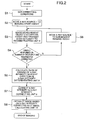
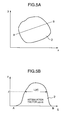
- Fig. 5A is an elevation showing a certain measurement object 2.
- Fig. 5B is a sectional view taken along line AB of the measurement object 2.
- z represents a height
- ⁇ (z, s) represents an attenuation factor of the measurement object 2 at coordinates s on line AB
- L(z) represents a length of the measurement object 2 at the height z.
- an X-ray passing through the measurement object 2 has a constant intensity.
- an average transmitting distance L m (z) of the X-ray beam is defined as formula (9) below:
- an X-ray passing through a substance having the average attenuation factor has an intensity I m expressed by the formula below:
- I m I o exp(- ⁇ 0 L m (z)) ⁇ 0 and L m (z) can be determined by the beam width of the X-ray, X-ray intensities measured by the detector 3 at two or more heights including the height z in the vertical direction, and a rate of change in intensity in the height direction.
- a CT image is reconstructed using I m in the CT image calculating unit 10.
- the above described correction is performed on X-ray intensities measured at all irradiation angles by all the radiation detectors constituting the detector 3.
- Correction is particularly necessary in an area where an X-ray intensity rapidly changes in the height direction, for example, in the case where the boundary surface of two substances having different attenuation factors is imaged as shown in Fig. 4.
- the number of cross sections used for correction can be determined and set properly based on a rate of change of the X-ray intensity in the imaging range.
- the number of cross sections can be inputted by the cross section number input unit 5. That is, the cross section number setting unit is provided for setting the number of different height positions for imaging the measurement object 2, thereby properly setting the number of cross sections and processing time.
- a position measurement number setting unit is provided for setting the number of measurements at different heights, thereby enabling the user to properly use the apparatus in view of imaging time and accuracy.
- a unit is provided for displaying imaging time and measuring accuracy according to the number of measurements. The number of measurements is set by the position measurement number setting unit.
- Fig. 7 is a side view showing the X-ray source 1 and the collimators of the detector 3, a method of setting a width of an X-ray beam will be discussed below.
- the width of the X-ray beam indicates a height of the X-ray beam at the center of rotation of the measurement object 2.
- the user inputs this value from the X-ray beam width input unit 6.
- the following method may be used instead of formula (11): an image of an object having a known shape such as a cylinder is photographed in the height direction, and the width of an X-ray beam is measured based on a change in X-ray intensity measured by the detector 3.
- the X-ray CT apparatus comprises an X-ray beam width measuring unit 11 instead of the X-ray beam width input unit 6 of Fig. 1.
- an X-ray intensity is measured in one of the radiation detectors of the detector 3 as shown in Fig 9.
- an X-ray intensity becomes constant.
- an X-ray intensity is changed according to a volume ratio of the measurement object 2 and the air layer in the transmission path of an X-ray beam. Therefore, as shown in Fig. 9, it is possible to determine a width of an X-ray based on a length permitting a change of an X-ray intensity.
- the X-ray beam width measuring unit 11 performs the above described processing using the X-ray intensity measured by the detector 3 and transmits the beam width of the X-ray to the X-ray intensity correcting unit 9.
- the width of an X-ray beam emitted from the X-ray source is inputted by the X-ray beam width input unit 6 and information on the width of the X-ray beam can be provided to the X-ray intensity correcting unit 9, thereby further improving measuring accuracy.
- the X-ray beam width measuring unit 11 is provided as a unit for measuring an amount of a beam width of an X-ray, it is possible to accurately measure the width of an X-ray beam emitted from the X-ray source and provide accurate information on the width of the X-ray beam for the X-ray intensity correcting unit 9, thereby further improving measuring accuracy.
- the amount of the width of the X-ray in the X-ray intensity correcting unit 9 it is possible to correct an error in dimensional measurements, the error being caused by the beam width of the X-ray in the height direction, and thus measuring accuracy can be further improved.
- a beam width setting unit is provided for setting data on a beam width of an X-ray used for measurements.
- a unit is provided for displaying imaging time and measuring accuracy according to a beam width set by the beam width setting unit.
- imaging time and measuring accuracy beforehand, which correspond to the number of measurements, and make a proper selection, thereby efficiently using the apparatus with ease. Further, the user can select whether imaging time or measuring accuracy should have higher priority according to the beam width of the X-ray.
- the process has to include an operation of estimating or measuring a beam width of the X-ray. Since the unit for inputting a beam width of an X-ray or the unit for measuring a beam width of an X-ray is provided, even when the X-ray source 1 is exchanged, it is possible to provide the X-ray intensity correcting unit 9 with a width of an X-ray beam emitted from a newly provided X-ray source 1.
- a third-generation X-ray CT apparatus In addition to the third-generation system, an X-ray CT apparatus of a second-generation system and an X-ray CT apparatus of a multislice system are available, which are shown in Figs. 10A and 10B and Figs. 11A and 11B.
- the measurement object 2 In the second-generation system, the measurement object 2 is moved along the direction of an arrow while being rotated and thus the measurement object 2 with a large size can be imaged.
- radiation detectors are arranged in the vertical direction as well as the horizontal direction in the detector 3 and thus a plurality of cross sections can be imaged at the same time. It is easy to assume that the imaging method of the present invention is also applicable to these imaging systems.
Landscapes
- Physics & Mathematics (AREA)
- General Physics & Mathematics (AREA)
- Engineering & Computer Science (AREA)
- Theoretical Computer Science (AREA)
- Health & Medical Sciences (AREA)
- Life Sciences & Earth Sciences (AREA)
- Pulmonology (AREA)
- Radiology & Medical Imaging (AREA)
- Nuclear Medicine, Radiotherapy & Molecular Imaging (AREA)
- Chemical & Material Sciences (AREA)
- Analytical Chemistry (AREA)
- Biochemistry (AREA)
- General Health & Medical Sciences (AREA)
- Immunology (AREA)
- Pathology (AREA)
- Apparatus For Radiation Diagnosis (AREA)
- Analysing Materials By The Use Of Radiation (AREA)
Applications Claiming Priority (2)
| Application Number | Priority Date | Filing Date | Title |
|---|---|---|---|
| JP2003358648A JP4062232B2 (ja) | 2003-10-20 | 2003-10-20 | X線ct装置及びx線ct装置による撮像方法 |
| JP2003358648 | 2003-10-20 |
Publications (2)
| Publication Number | Publication Date |
|---|---|
| EP1526482A2 true EP1526482A2 (fr) | 2005-04-27 |
| EP1526482A3 EP1526482A3 (fr) | 2005-06-29 |
Family
ID=34386448
Family Applications (1)
| Application Number | Title | Priority Date | Filing Date |
|---|---|---|---|
| EP04024849A Ceased EP1526482A3 (fr) | 2003-10-20 | 2004-10-19 | CT-scanner et méthode pour réduire l'effet non-linéaire de volume partiel dans un CT-scanner |
Country Status (4)
| Country | Link |
|---|---|
| US (1) | US7551710B2 (fr) |
| EP (1) | EP1526482A3 (fr) |
| JP (1) | JP4062232B2 (fr) |
| KR (1) | KR20050037955A (fr) |
Families Citing this family (3)
| Publication number | Priority date | Publication date | Assignee | Title |
|---|---|---|---|---|
| EP2252214A4 (fr) * | 2008-02-13 | 2013-05-29 | Kitware Inc | Méthode et système de mesure de lésions tissulaires et du risque pathologique |
| EP3129957B1 (fr) | 2014-04-07 | 2019-06-12 | Prismatic Sensors AB | Imagerie par rayons x spectrale |
| US10251612B2 (en) * | 2016-08-08 | 2019-04-09 | Carestream Health, Inc. | Method and system for automatic tube current modulation |
Citations (2)
| Publication number | Priority date | Publication date | Assignee | Title |
|---|---|---|---|---|
| EP0838784A1 (fr) | 1996-10-22 | 1998-04-29 | Ge Yokogawa Medical Systems, Ltd. | Procédé pour réduire des artifacts dans un tomographe |
| US6411670B1 (en) | 1999-11-17 | 2002-06-25 | General Electric Company | Data rebinning to increase resolution in CT image reconstruction |
Family Cites Families (64)
| Publication number | Priority date | Publication date | Assignee | Title |
|---|---|---|---|---|
| CH568569A5 (fr) * | 1974-02-06 | 1975-10-31 | Bbc Brown Boveri & Cie | |
| JPS52111775A (en) * | 1976-03-17 | 1977-09-19 | Nippon Kokan Kk | Temperature measuring instrument and method of using same |
| US4173869A (en) * | 1978-02-09 | 1979-11-13 | Westinghouse Electric Corp. | Apparatus and method for determining the rotor temperature of a steam turbine |
| US4247774A (en) * | 1978-06-26 | 1981-01-27 | The United States Of America As Represented By The Department Of Health, Education And Welfare | Simultaneous dual-energy computer assisted tomography |
| US4228356A (en) * | 1978-09-01 | 1980-10-14 | Pennwalt Corporation | Optimum contrast panoramic dental radiography and methods of providing therefor |
| US4408294A (en) * | 1981-03-27 | 1983-10-04 | General Electric Company | Method for on-line detection of incipient cracks in turbine-generator rotors |
| US4422177A (en) * | 1982-06-16 | 1983-12-20 | American Science And Engineering, Inc. | CT Slice proximity rotary table and elevator for examining large objects |
| US4468968A (en) * | 1983-04-21 | 1984-09-04 | The Singer Company | Method and arrangement for providing information to define the values of a set of parameters which characterize an element |
| DE3542159A1 (de) * | 1985-11-28 | 1987-06-04 | Nukem Gmbh | Verfahren zur werkstoffpruefung nach dem wirbelstromprinzip und vorrichtung zur durchfuehrung des verfahrens |
| JPS62145375A (ja) | 1985-12-20 | 1987-06-29 | Toshiba Corp | 3次元表示装置 |
| US5258923A (en) * | 1987-07-22 | 1993-11-02 | General Electric Company | System and method for detecting the occurrence, location and depth of cracks in turbine-generator rotors |
| JPH01124440A (ja) | 1987-11-10 | 1989-05-17 | Shimadzu Corp | コンピユータ断層装置 |
| US4788706A (en) * | 1987-12-17 | 1988-11-29 | General Electric Company | Method of measurement of x-ray energy |
| US5544212A (en) * | 1988-10-20 | 1996-08-06 | Picker International, Inc. | Spiral CT using an integrating interpolator |
| JPH02147942A (ja) | 1988-11-30 | 1990-06-06 | Fuji Electric Co Ltd | 内容物検査方法 |
| US4970670A (en) * | 1988-11-30 | 1990-11-13 | Westinghouse Electric Corp. | Temperature compensated eddy current sensor temperature measurement in turbine blade shroud monitor |
| US4987555A (en) * | 1988-11-30 | 1991-01-22 | Westinghouse Electric Corp. | Turbine blade shroud clearance monitor |
| US5119408A (en) * | 1990-10-31 | 1992-06-02 | General Electric Company | Rotate/rotate method and apparatus for computed tomography x-ray inspection of large objects |
| US5206816A (en) * | 1991-01-30 | 1993-04-27 | Westinghouse Electric Corp. | System and method for monitoring synchronous blade vibration |
| US5140264A (en) * | 1991-06-24 | 1992-08-18 | Westinghouse Electric Corp. | Method for non-destructively assessing the condition of a turbine blade using eddy current probes inserted within cooling holes |
| US5241576A (en) * | 1991-12-23 | 1993-08-31 | General Electric Company | Segmented detector containing sub-elements for separate measuring of a fan beam |
| US5226731A (en) * | 1992-05-28 | 1993-07-13 | Electric Power Research Institute | Apparatus for measuring rotor exhaust gas bulk temperature in a combustion turbine and method therefor |
| JPH0630922A (ja) | 1992-07-20 | 1994-02-08 | Toshiba Corp | X線ct装置 |
| MX9306169A (es) * | 1992-10-05 | 1995-01-31 | Fisher Controls Int | Calibracion de convertidor electro-neumatico. |
| US5371462A (en) * | 1993-03-19 | 1994-12-06 | General Electric Company | Eddy current inspection method employing a probe array with test and reference data acquisition and signal processing |
| US5698977A (en) * | 1993-10-12 | 1997-12-16 | The United States Of America As Represented By The Administrator Of The National Aeronautics And Space Administration | Eddy current method for fatigue testing |
| US5450462A (en) * | 1993-11-19 | 1995-09-12 | General Electric Company | Modulation of x-ray tube current during CT scanning with modulation limit |
| US5400378A (en) * | 1993-11-19 | 1995-03-21 | General Electric Company | Dynamic dose control in multi-slice CT scan |
| US5430784A (en) * | 1994-02-28 | 1995-07-04 | General Electric Company | Computerized tomography imaging using multi-slice detector with selectable slice thickness |
| US5596271A (en) * | 1994-05-03 | 1997-01-21 | Multicraft International | Method of and apparatus for detecting the rotation rate of an air moving fan |
| DE19502574C2 (de) * | 1995-01-27 | 1999-09-23 | Siemens Ag | Röntgen-Computertomograph |
| US6657429B1 (en) * | 1995-08-25 | 2003-12-02 | Jentek Sensors, Inc. | Material condition assessment with spatially periodic field sensors |
| DE19625863C2 (de) * | 1996-06-27 | 2002-06-27 | Siemens Ag | Verfahren zur Bildrekonstruktion für einen im Spiralbetrieb arbeitenden Computertomographen |
| IL119033A0 (en) * | 1996-08-07 | 1996-11-14 | Elscint Ltd | Multi-slice detector array |
| US5696807A (en) * | 1996-09-05 | 1997-12-09 | General Electric Company | Methods and apparatus for modulating x-ray tube current |
| US5808202A (en) * | 1997-04-04 | 1998-09-15 | Passarelli, Jr.; Frank | Electromagnetic acoustic transducer flaw detection apparatus |
| US5970112A (en) * | 1998-03-25 | 1999-10-19 | General Electric Company | Smart collimation based on a single scout scan in a computed tomography system |
| US6094989A (en) * | 1998-08-21 | 2000-08-01 | Siemens Westinghouse Power Corporation | Method and apparatus for analyzing non-synchronous blade vibrations using unevenly spaced probes |
| US6173029B1 (en) * | 1998-08-25 | 2001-01-09 | General Electric Company | Higher order detector z-slope correction for a multislice computed tomography system |
| US6141398A (en) * | 1998-08-25 | 2000-10-31 | General Electric Company | Protocol driven image reconstruction, display, and processing in a multislice imaging system |
| US6198791B1 (en) * | 1998-08-25 | 2001-03-06 | General Electric Company | Scalable multislice imaging system |
| US6785635B2 (en) * | 1999-08-02 | 2004-08-31 | Hood Technology Corporation | Apparatus and method for predicting failures of spinning disks in turbo-machinery |
| US6594619B1 (en) * | 1999-08-02 | 2003-07-15 | Hood Technology Corporation | Apparatus and method for predicting failures of spinning disks in turbo-machinery |
| US6385279B1 (en) * | 1999-08-27 | 2002-05-07 | General Electric Company | Methods and apparatus for positioning a CT imaging x-ray beam |
| US7161350B2 (en) * | 1999-09-07 | 2007-01-09 | Jentek Sensors, Inc. | Method for material property monitoring with perforated, surface mounted sensors |
| US6346807B1 (en) * | 1999-10-22 | 2002-02-12 | Bently Nevada Corporation | Digital eddy current proximity system: apparatus and method |
| DE19961093A1 (de) * | 1999-12-17 | 2001-06-21 | Siemens Ag | Verfahren zur Erzeugung eines resultierenden Schnittbildes aus mehreren mittels eines Computertomographie(CT)-Geräts aufgenommenen Schnittbildern |
| DE19962735A1 (de) * | 1999-12-23 | 2001-06-28 | Alstom Power Schweiz Ag Baden | Verfahren zur Überwachung des Kriechverhaltens rotierender Komponenten einer Verdichter- oder Turbinenstufe |
| US6504898B1 (en) * | 2000-04-17 | 2003-01-07 | Mds (Canada) Inc. | Product irradiator for optimizing dose uniformity in products |
| JP4087547B2 (ja) | 2000-05-19 | 2008-05-21 | 東芝Itコントロールシステム株式会社 | コンピュータ断層撮影装置 |
| JP3442346B2 (ja) | 2000-06-01 | 2003-09-02 | カナガワ アンド カンパニー株式会社 | 画像形成装置及びこれを用いた画像の構成方法 |
| US6658082B2 (en) * | 2000-08-14 | 2003-12-02 | Kabushiki Kaisha Toshiba | Radiation detector, radiation detecting system and X-ray CT apparatus |
| FR2815123B1 (fr) * | 2000-10-10 | 2003-02-07 | Snecma Moteurs | Controle acoustique de roues aubagees monoblocs |
| US6483890B1 (en) * | 2000-12-01 | 2002-11-19 | Koninklijke Philips Electronics, N.V. | Digital x-ray imaging apparatus with a multiple position irradiation source and improved spatial resolution |
| US6470068B2 (en) * | 2001-01-19 | 2002-10-22 | Cheng Chin-An | X-ray computer tomography scanning system |
| US6784662B2 (en) * | 2001-03-19 | 2004-08-31 | Jentek Sensors, Inc. | Eddy current sensor arrays having drive windings with extended portions |
| US6965661B2 (en) * | 2001-06-19 | 2005-11-15 | Hitachi, Ltd. | Radiological imaging apparatus and radiological imaging method |
| JP2004520923A (ja) * | 2001-06-20 | 2004-07-15 | コーニンクレッカ フィリップス エレクトロニクス エヌ ヴィ | デジタル画像をセグメント化する方法 |
| DE10141346A1 (de) * | 2001-08-23 | 2003-06-26 | Siemens Ag | Verfahren zur Aufnahme von Messdaten mit einem Computertormographen |
| AU2001288024A1 (en) * | 2001-09-05 | 2003-03-18 | Koninklijke Philips Electronics N.V. | Dose control in ct-images |
| US6922457B2 (en) * | 2001-11-29 | 2005-07-26 | Kabushiki Kaisha Toshiba | Computer tomography apparatus |
| US6692222B2 (en) * | 2002-05-14 | 2004-02-17 | The Board Of Trustees Of The Leland Stanford Junior University | Micro gas turbine engine with active tip clearance control |
| US6661222B1 (en) * | 2002-05-31 | 2003-12-09 | Siemens Westinghouse Power Corporation | Turbine blade clearance on-line measurement system |
| US7433507B2 (en) * | 2003-07-03 | 2008-10-07 | Ge Medical Systems Global Technology Co. | Imaging chain for digital tomosynthesis on a flat panel detector |
-
2003
- 2003-10-20 JP JP2003358648A patent/JP4062232B2/ja not_active Expired - Lifetime
-
2004
- 2004-10-19 EP EP04024849A patent/EP1526482A3/fr not_active Ceased
- 2004-10-19 KR KR1020040083360A patent/KR20050037955A/ko not_active Withdrawn
- 2004-10-20 US US10/968,027 patent/US7551710B2/en not_active Expired - Fee Related
Patent Citations (2)
| Publication number | Priority date | Publication date | Assignee | Title |
|---|---|---|---|---|
| EP0838784A1 (fr) | 1996-10-22 | 1998-04-29 | Ge Yokogawa Medical Systems, Ltd. | Procédé pour réduire des artifacts dans un tomographe |
| US6411670B1 (en) | 1999-11-17 | 2002-06-25 | General Electric Company | Data rebinning to increase resolution in CT image reconstruction |
Also Published As
| Publication number | Publication date |
|---|---|
| US7551710B2 (en) | 2009-06-23 |
| JP2005121557A (ja) | 2005-05-12 |
| EP1526482A3 (fr) | 2005-06-29 |
| US20050084061A1 (en) | 2005-04-21 |
| KR20050037955A (ko) | 2005-04-25 |
| JP4062232B2 (ja) | 2008-03-19 |
Similar Documents
| Publication | Publication Date | Title |
|---|---|---|
| CN108292428B (zh) | 图像重建的系统和方法 | |
| US8000435B2 (en) | Method and system for error compensation | |
| US6339652B1 (en) | Source-assisted attenuation correction for emission computed tomography | |
| JP5264268B2 (ja) | 単位面積質量画像の作成方法 | |
| RU2524053C2 (ru) | Способ непрерывного моделирования времяпролетного рассеяния | |
| US10255696B2 (en) | System and method for image reconstruction | |
| US10902650B2 (en) | X-ray beam-hardening correction in tomographic reconstruction using the Alvarez-Macovski attenuation model | |
| US20200249179A1 (en) | Method and apparatus for processing photon-counting x-ray detection data and x-ray apparatus | |
| US8290116B2 (en) | Imaging apparatus including correction unit for scattered radiation | |
| CN101266216A (zh) | 标定双能ct系统的方法和图像重建方法 | |
| CN101040781B (zh) | X射线衰减校正方法、ct装置、图像产生装置及方法 | |
| JPH07184886A (ja) | コンピュータ断層撮影用の装置及び方法 | |
| CN101080651B (zh) | 成像系统及成像方法 | |
| Herl et al. | Artifact reduction in X-ray computed tomography by multipositional data fusion using local image quality measures | |
| US6921902B2 (en) | Scatter correction device for radiative tomographic scanner | |
| US7471813B2 (en) | Systems and methods for correction of scatter in images | |
| US7519143B2 (en) | Method and system for generating a scatter corrected X-ray image | |
| EP1526482A2 (fr) | CT-scanner et méthode pour réduire l'effet non-linéaire de volume partiel dans un CT-scanner | |
| CN108065950B (zh) | 一种放射成像方法及其系统 | |
| US20100254585A1 (en) | Overexposure correction for large volume reconstruction in computed tomography apparatus | |
| US11113810B2 (en) | X-ray CT scanner, image generation method, and image generation program | |
| US7385200B2 (en) | Re-binning method for nuclear medicine imaging devices | |
| Fleming et al. | A rule based method for context sensitive threshold segmentation in SPECT using simulation | |
| Souza et al. | Determination of a neutron beam divergence after the rocking curve concept using Richardson–Lucy’s unfolding algorithm | |
| US12500058B1 (en) | Radiation focal spot to port measurement device, system, and method |
Legal Events
| Date | Code | Title | Description |
|---|---|---|---|
| PUAI | Public reference made under article 153(3) epc to a published international application that has entered the european phase |
Free format text: ORIGINAL CODE: 0009012 |
|
| AK | Designated contracting states |
Kind code of ref document: A2 Designated state(s): AT BE BG CH CY CZ DE DK EE ES FI FR GB GR HU IE IT LI LU MC NL PL PT RO SE SI SK TR |
|
| AX | Request for extension of the european patent |
Extension state: AL HR LT LV MK |
|
| PUAL | Search report despatched |
Free format text: ORIGINAL CODE: 0009013 |
|
| AK | Designated contracting states |
Kind code of ref document: A3 Designated state(s): AT BE BG CH CY CZ DE DK EE ES FI FR GB GR HU IE IT LI LU MC NL PL PT RO SE SI SK TR |
|
| AX | Request for extension of the european patent |
Extension state: AL HR LT LV MK |
|
| 17P | Request for examination filed |
Effective date: 20051020 |
|
| AKX | Designation fees paid |
Designated state(s): DE FR |
|
| STAA | Information on the status of an ep patent application or granted ep patent |
Free format text: STATUS: THE APPLICATION HAS BEEN REFUSED |
|
| 18R | Application refused |
Effective date: 20101104 |