EP1526418A2 - System comprised of a domestic appliance and an external device - Google Patents
System comprised of a domestic appliance and an external device Download PDFInfo
- Publication number
- EP1526418A2 EP1526418A2 EP04023726A EP04023726A EP1526418A2 EP 1526418 A2 EP1526418 A2 EP 1526418A2 EP 04023726 A EP04023726 A EP 04023726A EP 04023726 A EP04023726 A EP 04023726A EP 1526418 A2 EP1526418 A2 EP 1526418A2
- Authority
- EP
- European Patent Office
- Prior art keywords
- receiving part
- search code
- code
- household appliance
- stored
- Prior art date
- Legal status (The legal status is an assumption and is not a legal conclusion. Google has not performed a legal analysis and makes no representation as to the accuracy of the status listed.)
- Ceased
Links
Images
Classifications
-
- H—ELECTRICITY
- H04—ELECTRIC COMMUNICATION TECHNIQUE
- H04L—TRANSMISSION OF DIGITAL INFORMATION, e.g. TELEGRAPHIC COMMUNICATION
- H04L12/00—Data switching networks
- H04L12/28—Data switching networks characterised by path configuration, e.g. LAN [Local Area Networks] or WAN [Wide Area Networks]
- H04L12/2803—Home automation networks
- H04L12/2838—Distribution of signals within a home automation network, e.g. involving splitting/multiplexing signals to/from different paths
-
- G—PHYSICS
- G05—CONTROLLING; REGULATING
- G05B—CONTROL OR REGULATING SYSTEMS IN GENERAL; FUNCTIONAL ELEMENTS OF SUCH SYSTEMS; MONITORING OR TESTING ARRANGEMENTS FOR SUCH SYSTEMS OR ELEMENTS
- G05B19/00—Program-control systems
- G05B19/02—Program-control systems electric
- G05B19/04—Program control other than numerical control, i.e. in sequence controllers or logic controllers
- G05B19/042—Program control other than numerical control, i.e. in sequence controllers or logic controllers using digital processors
- G05B19/0428—Safety, monitoring
-
- H—ELECTRICITY
- H04—ELECTRIC COMMUNICATION TECHNIQUE
- H04L—TRANSMISSION OF DIGITAL INFORMATION, e.g. TELEGRAPHIC COMMUNICATION
- H04L12/00—Data switching networks
- H04L12/28—Data switching networks characterised by path configuration, e.g. LAN [Local Area Networks] or WAN [Wide Area Networks]
- H04L12/2803—Home automation networks
- H04L12/2823—Reporting information sensed by appliance or service execution status of appliance services in a home automation network
Definitions
- the invention relates to a system referred to in the preamble of claim 1 Art.
- the known System consists of a household appliance and an external device, in particular for Parameterization, fault diagnosis and remote maintenance of the household appliance.
- the one device has a transmitting part and the other device a receiving part, which is for the exchange of electromagnetic radiation in the wavelength range of visible light or infrared are formed and by an actuation of an actuating means to the respective Device are activated.
- By activating the transmission part of this is continuously one previously defined and stored in a memory of the transmitting part, of a plurality from code words of different code, existing search code can be sent out.
- a Processing unit of the receiving part are received from the receiving part with signals the search code stored in a further memory of the receiving part comparable.
- a predetermined response signal can be output.
- the search code consists of a sequence of at least three different codewords and the individual ones Sequences are separated from each other by a pause interval.
- the invention thus addresses the problem of a household appliance and an external Device to specify existing system, in which by a human eye identifiable identification of an interface for signal or data exchange between the Domestic appliance and the external device can be dispensed with the household appliance, without thereby impairing the ease of use for the user while providing security unwanted response signals at the same time rapid response of the receiving part to improve.
- the achievable with the invention advantages are in addition to the possibility of a through the human eye recognizable identification of an interface to the signal or Data exchange between the home appliance and the external device on the To be able to do without a domestic appliance, without the ease of use for the user deteriorate, in particular that, for example, a printing of the control panel or the like may be omitted for marking the interface on the household appliance.
- the control panel is easier and cheaper to produce.
- the overall visual impression of the control panel improves or it is possible, the Control panel without regard to a required marking of the area of the Interface to the household appliance.
- the search code consists of a sequence of at least three different ones Codewords and the individual sequences are separated from each other by a pause interval.
- the output of a response signal is due to any electromagnetic Disturbing radiation, for example from other electrical devices, safely prevented and at the same time a fast response of the receiving part to the received signals guaranteed.
- the pause interval in which the continuous transmission of the search code is briefly interrupted, this can also be used as a receiver for electromagnetic radiation, such as For example, the response signal, trained transmitting part itself receive signals and to process.
- the response signal can be selected according to type and duration within wide suitable limits.
- the response signal is one consisting of a single codeword Response code formed, which is transmitted from the receiving part to the transmitting part.
- the Response signal on a display and / or via a speaker at least one of both devices a perceptible by the human sensory organs acoustic and / or optical detection signal triggers. This is an immediate and easily recognizable Information of the user about the progress of the search process allows.
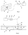
- FIG. 1 an inventive system is shown partially and greatly simplified.
- the System consists of a in Fig. 1 only indicated with the control panel 2 Domestic appliance 4 and an external device, not shown in Fig. 1, in particular for Paramtetritation, fault diagnosis and remote maintenance of the household appliance 4, here the external device is designed as a portable customer service computer.
- the transportable After-sales computer also has a speaker, not shown, via the one recognizable by the human ear audible detection signal is deliverable.
- the external device has a transmitting part 6 and the Domestic appliance 4 a not shown in Fig.
- both the transmitting part 6 as well as the receiving part are each as a transmitter and at the same time as a receiver of electromagnetic radiation, here infrared radiation, educated. This makes it possible to exchange bidirectional signals.
- the transmitting part 6 has a memory and a processing unit existing Assembly 8, wherein in the memory 8 a predetermined and from at least three of from each other code words existing search code is stored.
- the search code consists of three different from each other Codewords, in hexadecimal notation for example F0, CC and AA.
- points the transmitting part 6 an opto-electric converter 10, to which a transmitting head 12 by means of a Light guide 14 is connected.
- the opto-electric converter 10 by means of a cable 16 to the memory 8 in signal transmission connection.
- the opto-electric converter 10 has an LED, not shown, by means of a detectable by the human eye detection signal can be emitted.
- the structure of the receiving part will be explained in more detail with reference to FIG. 2.
- FIG. 2 is apparent behind the control panel 2 in the direction of the interior of the household appliance 4 a Board 18 arranged.
- On the board 18 is common among others in household appliances Components, such as a display unit 20, the receiving part arranged.
- the Receiving part has a processing unit and another memory, which to a Assembly 22 are summarized, another opto-electric converter 24 and a further light guide 26.
- the further memory is the search code explained in more detail above and a predetermined response signal stored, wherein the response signal of the present embodiment as one of a single code word, in Hexadecimal representation, for example, 00, existing response code is formed.
- the additional light guide 26 is required in this embodiment to the distance between the control panel 2 and the other opto-electric converter 24 to bridge.
- the area of the control panel, with the other light guide 26 is in contact, namely area 28, for infrared radiation, ie for the wavelength range the exchanged signals are permeable.
- the household appliance 4 is turned on, so that the receiving part is activated.
- the Customer service representative turns on the portable customer service computer and starts a search function that activates the transmission part 6.
- the Transmitter 6 With the start of the search function, the Transmitter 6 in the manner known in the art in the memory of the unit. 8 stored search code continuously by means of the transmitting head 12 in the free environment.
- the radiated by the transmitting head 12 search code of the Receive part received, via the other light guide 26 and the other opto-electric converter 24 in the manner known to those skilled in the assembly 22 arranged in the Processing unit of the receiving part forwarded.
- the received signals in an evaluation circuit of the processing unit of the receiving part with the search code stored in the further memory known to the person skilled in the art Way compared.
- Voices the received signals with the stored search code which is the case in the present example will be the same in the further memory stored response signal in an analogous manner to the aforementioned search code of the Receive part transmitted to the transmitting part.
- the present embodiment is this in each case between the individual sequences of the continuously transmitted search code Pausenintervall provided during which the continuous transmission of the search code is temporarily interrupted.
- a circuitry simpler solution provides that the LED of the opto-electric converter 10 directly through which the opto-electric converter 10 of the Receiving part in the direction of transmitting part 6 passing electrical signals, so due to the electric current flow, is turned on.
- the customer service representative becomes accordingly informed by both the lit LED as well as the beep that the transmitting head 12 is located in the area 28 of the control panel 2, so that a further signal or data exchange between the household appliance 4 and the portable Customer service computer can be done in a manner known to those skilled in the art.
- the emitted from the transmitting head 12 would Search code by the receiving part due to the increasing distance between the Transmitter head 12 and the receiving part and / or the fact that the transmitting head 12 with the Perpendicular to the search code radiating surface no longer in the direction of the area 28 or the receiving part has, no more or at least not for the evaluation by the Receiving part received sufficiently strong signal.
Landscapes
- Engineering & Computer Science (AREA)
- Automation & Control Theory (AREA)
- Computer Networks & Wireless Communication (AREA)
- Signal Processing (AREA)
- Physics & Mathematics (AREA)
- General Physics & Mathematics (AREA)
- Multimedia (AREA)
- Selective Calling Equipment (AREA)
- Optical Communication System (AREA)
Abstract
Die Erfindung betrifft ein System, bestehend aus einem Haushaltsgerät und einem externen Gerät, insbesondere zur Parametrierung, Fehlerdiagnose und Fernwartung des Haushaltsgeräts, wobei das eine Gerät ein Sendeteil und das andere Gerät ein Empfangsteil aufweist, die zum Austausch von elektromagnetischer Strahlung in dem Wellenlängenbereich von sichtbaren Licht oder Infrarot ausgebildet sind und durch eine Betätigung jeweils eines Betätigungsmittels an dem jeweiligen Gerät aktivierbar sind.The invention relates to a system consisting of a household appliance and an external Device, in particular for parameterization, fault diagnosis and remote maintenance of the Domestic appliance, wherein the one device is a transmitting part and the other device is a receiving part having for exchanging electromagnetic radiation in the wavelength range are formed by visible light or infrared and by an actuation of each one Actuating means are activated on the respective device.
Um ein aus einem Haushaltsgerät (4) und einem externen Gerät bestehendes System
anzugeben, bei dem auf eine durch das menschliche Auge erkennbare Kennzeichnung einer
Schnittstelle zum Datenaustausch zwischen dem Haushaltsgerät (4) und dem externen Gerät
an dem Haushaltsgerät (4) verzichtet werden kann, ohne dabei den Bedienkomfort für den
Benutzer zu verschlechtern schlägt die Erfindung vor, dass durch die Aktivierung des
Sendeteils (6) von diesem fortlaufend ein vorher festgelegter und in einem Speicher des
Sendeteils (6) abgespeicherter, aus einer Mehrzahl von voneinander verschiedenen
Codewörtern bestehender, Suchcode aussendbar ist und in einer Verarbeitungseinheit des
Empfangsteils von dem Empfangsteil empfangene Signale mit dem in einem weiteren Speicher
des Empfangsteils abgespeicherten Suchcode vergleichbar sind und bei Übereinstimmung der
empfangenen Signale mit dem Suchcode mittels des Empfangsteils ein vorher festgelegtes
Antwortsignal ausgebbar ist.

Description
Die Erfindung betrifft ein System der im Oberbegriff des Anspruchs 1 genannten Art.The invention relates to a system referred to in the preamble of claim 1 Art.
Ein derartiges System ist beispielsweise aus der DE 694 18 377 T2 bekannt. Das bekannte System besteht aus einem Haushaltsgerät und einem externen Gerät, insbesondere zur Parametrierung, Fehlerdiagnose und Fernwartung des Haushaltsgeräts. Das eine Gerät weist ein Sendeteil und das andere Gerät ein Empfangsteil auf, die zum Austausch von elektromagnetischer Strahlung in dem Wellenlängenbereich von sichtbaren Licht oder Infrarot ausgebildet sind und durch eine Betätigung jeweils eines Betätigungsmittels an dem jeweiligen Gerät aktivierbar sind. Durch die Aktivierung des Sendeteils ist von diesem fortlaufend ein vorher festgelegter und in einem Speicher des Sendeteils abgespeicherter, aus einer Mehrzahl von voneinander verschiedenen Codewörtern bestehender, Suchcode aussendbar. In einer Verarbeitungseinheit des Empfangsteils sind von dem Empfangsteil empfangene Signale mit dem in einem weiteren Speicher des Empfangsteils abgespeicherten Suchcode vergleichbar. Bei Übereinstimmung der empfangenen Signale mit dem Suchcode ist mittels des Empfangsteils ein vorher festgelegtes Antwortsignal ausgebbar. Der Suchcode besteht aus einer Abfolge von mindestens drei voneinander verschiedenen Codewörtern und die einzelnen Abfolgen sind voneinander durch ein Pausenintervall getrennt.Such a system is known for example from DE 694 18 377 T2. The known System consists of a household appliance and an external device, in particular for Parameterization, fault diagnosis and remote maintenance of the household appliance. The one device has a transmitting part and the other device a receiving part, which is for the exchange of electromagnetic radiation in the wavelength range of visible light or infrared are formed and by an actuation of an actuating means to the respective Device are activated. By activating the transmission part of this is continuously one previously defined and stored in a memory of the transmitting part, of a plurality from code words of different code, existing search code can be sent out. In a Processing unit of the receiving part are received from the receiving part with signals the search code stored in a further memory of the receiving part comparable. In accordance with the received signals with the search code is by means of the Receiving part, a predetermined response signal can be output. The search code consists of a sequence of at least three different codewords and the individual ones Sequences are separated from each other by a pause interval.
Ferner ist aus der DE 196 15 358 A1 eine Anzeigesteuerung für eine Anzeigevorrichtung eines Haushaltsgeräts bekannt, bei der die Daten mehrerer gleichzeitig betriebener Haushaltsgeräte seriell oder parallel auf der Anzeigevorrichtung darstellbar sind. Hierzu ist in einer Ausführungsform eine drahtlose Datenübertragung vorgesehen.Furthermore, from DE 196 15 358 A1 a display control for a display device of Household appliance known in which the data of several simultaneously operated household appliances can be displayed serially or in parallel on the display device. This is in one Embodiment provided a wireless data transmission.
Der Erfindung stellt sich somit das Problem ein aus einem Haushaltsgerät und einem externen Gerät bestehendes System anzugeben, bei dem auf eine durch das menschliche Auge erkennbare Kennzeichnung einer Schnittstelle zum Signal- oder Datenaustausch zwischen dem Haushaltsgerät und dem externen Gerät an dem Haushaltsgerät verzichtet werden kann, ohne dabei den Bedienkomfort für den Benutzer zu verschlechtern und dabei die Sicherheit vor ungewünschten Antwortsignalen bei gleichzeitig schneller Reaktion des Empfangsteils zu verbessern.The invention thus addresses the problem of a household appliance and an external Device to specify existing system, in which by a human eye identifiable identification of an interface for signal or data exchange between the Domestic appliance and the external device can be dispensed with the household appliance, without thereby impairing the ease of use for the user while providing security unwanted response signals at the same time rapid response of the receiving part to improve.
Erfindungsgemäß wird dieses Problem durch ein System mit den Merkmalen des Patentanspruchs 1 gelöst. Vorteilhafte Ausgestaltungen und Weiterbildungen der Erfindung ergeben sich aus den nachfolgenden Unteransprüchen. According to the invention, this problem is solved by a system having the features of Patent claim 1 solved. Advantageous embodiments and developments of the invention emerge from the following subclaims.
Die mit der Erfindung erreichbaren Vorteile bestehen neben der Möglichkeit, auf eine durch das menschliche Auge erkennbare Kennzeichnung einer Schnittstelle zum Signal- oder Datenaustausch zwischen dem Haushaltsgerät und dem externen Gerät an dem Haushaltsgerät verzichten zu können, ohne dabei den Bedienkomfort für den Benutzer zu verschlechtern, insbesondere darin, dass beispielsweise eine Bedruckung der Bedienblende oder dergleichen zur Kennzeichnung der Schnittstelle an dem Haushaltsgerät entfallen kann. Hierdurch ist die Bedienblende einfacher und kostengünstiger herstellbar. Darüber hinaus wird der optische Gesamteindruck der Bedienblende verbessert bzw. ist es möglich, die Bedienblende ohne Rücksicht auf eine erforderliche Kennzeichnung des Bereichs der Schnittstelle an dem Haushaltsgerät zu gestalten.The achievable with the invention advantages are in addition to the possibility of a through the human eye recognizable identification of an interface to the signal or Data exchange between the home appliance and the external device on the To be able to do without a domestic appliance, without the ease of use for the user deteriorate, in particular that, for example, a printing of the control panel or the like may be omitted for marking the interface on the household appliance. As a result, the control panel is easier and cheaper to produce. In addition, will the overall visual impression of the control panel improves or it is possible, the Control panel without regard to a required marking of the area of the Interface to the household appliance.
Der Suchcode besteht aus einer Abfolge von mindestens drei voneinander verschiedenen Codewörtern und die einzelnen Abfolgen sind voneinander durch ein Pausenintervall getrennt. Auf diese Weise ist die Ausgabe eines Antwortsignals aufgrund etwaiger elektromagnetischer Störstrahlungen, beispielsweise von anderen elektrischen Geräten, sicher verhindert und gleichzeitig eine schnelle Reaktion des Empfangsteils auf die empfangenen Signale gewährleistet. Durch das Pausenintervall, in dem die fortlaufende Aussendung des Suchcodes kurzzeitig unterbrochen ist, kann das auch als Empfänger für elektromagnetische Strahlung, wie beispielsweise das Antwortsignal, ausgebildete Sendeteil selbst Signale empfangen und verarbeiten.The search code consists of a sequence of at least three different ones Codewords and the individual sequences are separated from each other by a pause interval. In this way, the output of a response signal is due to any electromagnetic Disturbing radiation, for example from other electrical devices, safely prevented and at the same time a fast response of the receiving part to the received signals guaranteed. By the pause interval, in which the continuous transmission of the search code is briefly interrupted, this can also be used as a receiver for electromagnetic radiation, such as For example, the response signal, trained transmitting part itself receive signals and to process.
Da der Vergleich der empfangenen Signale mit dem abgespeicherten Suchcode in dem Empfangsteil erst nach dem Empfang von mindestens fünf hintereinander empfangenen Codewörtern beginnt, ist die Sicherheit vor ungewünschten Antwortsignalen bei gleichzeitig schneller Reaktion des Empfangsteils verbessert.Since the comparison of the received signals with the stored search code in the Receive part only after receiving at least five consecutively received Codewords starts at the same time as the security against unwanted response signals improved response of the receiving part improved.
Grundsätzlich ist das Antwortsignal nach Art und Dauer in weiten geeigneten Grenzen wählbar. Zweckmäßigerweise ist das Antwortsignal als ein aus einem einzigen Codewort bestehender Antwortcode ausgebildet, der von dem Empfangsteil an das Sendeteil übermittelbar ist.In principle, the response signal can be selected according to type and duration within wide suitable limits. Conveniently, the response signal is one consisting of a single codeword Response code formed, which is transmitted from the receiving part to the transmitting part.
Eine andere vorteilhafte Weiterbildung der erfindungsgemäßen Lehre sieht vor, dass das Antwortsignal auf einer Anzeige und/oder über einen Lautsprecher wenigstens von einem der beiden Geräte ein von den menschlichen Sinnesorganen wahrnehmbares akustisches und/oder optisches Erkennungssignal auslöst. Hierdurch ist eine unmittelbare und leicht erkennbare Information des Benutzers über den Fortschritt des Suchvorgangs ermöglicht.Another advantageous development of the teaching of the invention provides that the Response signal on a display and / or via a speaker at least one of both devices a perceptible by the human sensory organs acoustic and / or optical detection signal triggers. This is an immediate and easily recognizable Information of the user about the progress of the search process allows.
Ein Ausführungsbeispiel der Erfindung ist in den Zeichnungen rein schematisch dargestellt und wird nachfolgend näher beschrieben. Es zeigt
- Figur 1
- ein erfindungsgemäßes System in teilweiser perspektivischer Darstellung und
Figur 2- eine Detailansicht des Systems aus Fig. 1 in teilweiser Schnittdarstellung.
- FIG. 1
- an inventive system in partial perspective view and
- FIG. 2
- a detailed view of the system of FIG. 1 in a partial sectional view.
In Fig. 1 ist ein erfindungsgemäßes System teilweise und stark vereinfacht dargestellt. Das
System, besteht aus einem in Fig. 1 lediglich mit der Bedienblende 2 angedeuteten
Haushaltsgerät 4 und einem in Fig. 1 nicht dargestellten externen Gerät, insbesondere zur
Paramtetrierung, Fehlerdiagnose und Fernwartung des Haushaltsgeräts 4, wobei hier das
externe Gerät als ein transportabler Kundendienstcomputer ausgebildet ist. Der transportable
Kundendienstcomputer weist darüber hinaus einen nicht dargestellten Lautsprecher auf, über
den ein von dem menschlichen Gehör wahrnehmbares akustisches Erkennungssignal
abgebbar ist. Bei diesem Ausführungsbeispiel weist das externe Gerät ein Sendeteil 6 und das
Haushaltsgerät 4 ein in Fig. 1 nicht dargestelltes Empfangsteil auf, die zum Austausch von
elektromagnetischer Strahlung in dem Wellenlängenbereich von Infrarot ausgebildet sind und
durch eine Betätigung jeweils eines nicht dargestellten Betätigungsmittels an dem jeweiligen
Gerät, Haushaltsgerät 4 und externes Gerät, aktivierbar sind. Bei dem vorliegenden
Ausführungsbeispiel sind sowohl das Sendeteil 6 wie auch das Empfangsteil jeweils als Sender
und gleichzeitig als Empfänger von elektromagnetischer Strahlung, hier Infrarotstrahlung,
ausgebildet. Hierdurch ist es möglich bidirektional Signale auszutauschen.In Fig. 1, an inventive system is shown partially and greatly simplified. The
System, consists of a in Fig. 1 only indicated with the
Das Sendeteil 6 weist ein aus einem Speicher und einer Verarbeitungseinheit bestehende
Baueinheit 8 auf, wobei in dem Speicher 8 ein vorher festgelegter und aus mindestens drei von
voneinander verschiedenen Codewörtern bestehender Suchcode abgespeichert ist. Bei dem
vorliegenden Ausführungsbeispiel besteht der Suchcode aus drei voneinander verschiedenen
Codewörtern, in Hexadezimaldarstellung beispielsweise F0, CC und AA. Darüber hinaus weist
das Sendeteil 6 einen Opto-Elektrowandler 10 auf, an dem ein Sendekopf 12 mittels eines
Lichtleiters 14 anschließbar ist. Bei dem vorliegenden Ausführungsbeispiel ist der Opto-Elektrowandler
10 mittels eines Kabels 16 mit dem Speicher 8 in Signalübertragungsverbindung.
Ferner weist der Opto-Elektrowandler 10 eine nicht dargestellte LED auf, mittels
der ein von dem menschlichen Auge wahrnehmbares Erkennungssignal abgebbar ist. Alternativ
zu dem hier vorliegenden Ausführungsbeispiel ist es auch denkbar, dass die genannten
Bestandteile des Sendeteils 6, nämlich der Opto-Elektrowandler 10 und der Sendekopf 12
sowie der Lichtleiter 14 und das Kabel 16 in einer gemeinsamen Baueinheit zusammengefasst
sind. Der Vorteil des vorliegenden Ausführungsbeispiels besteht in einem verbesserten
Bedienkomfort für den Benutzer, da dieser, wie nachfolgend näher erläutert, lediglich den
Sendekopf 12 halten und bewegen muss. The transmitting
Der Aufbau des Empfangsteils wird anhand von Fig. 2 näher erläutert. Wie aus Fig. 2
hervorgeht, ist hinter der Bedienblende 2 in Richtung des Inneren des Haushaltsgeräts 4 eine
Platine 18 angeordnet. Auf der Platine 18 ist neben anderen bei Haushaltsgeräten üblichen
Bauteilen, wie beispielsweise einer Anzeigeeinheit 20 das Empfangsteil angeordnet. Das
Empfangsteil weist eine Verarbeitungseinheit und einen weiteren Speicher, die zu einer
Baueinheit 22 zusammengefasst sind, einen weiteren Opto-Elektrowandler 24 und einen
weiteren Lichtleiter 26 auf. In dem weiteren Speicher ist der oben näher erläuterte Suchcode
und ein vorher festgelegtes Antwortsignal abgespeichert, wobei das Antwortsignal des
vorliegenden Ausführungsbeispiels als ein aus einem einzigen Codewort, in
Hexadezimaldarstellung beispielsweise 00, bestehender Antwortcode ausgebildet ist. Der
weitere Lichtleiter 26 ist bei diesem Ausführungsbeispiel erforderlich, um den Abstand zwischen
der Bedienblende 2 und dem weiteren Opto-Elektrowandler 24 zu überbrücken. Alternativ
hierzu sind andere Ausführungsbeispiele denkbar, bei denen ein derartiger weiterer Lichtleiter
26 nicht erforderlich ist. Damit ein Signalaustausch zwischen dem Sendekopf 12 und dem
Empfangsteil möglich ist, muss der Bereich der Bedienblende, der mit dem weiteren Lichtleiter
26 in Kontakt steht, nämlich Bereich 28, für Infrarotstrahlung, also für den Wellenlängenbereich
der ausgetauschten Signale durchlässig ausgebildet sein.The structure of the receiving part will be explained in more detail with reference to FIG. 2. As shown in FIG. 2
is apparent behind the
Nachfolgend wird die Funktionsweise des obigen Ausführungsbeispiels des erfindungsgemäßen Systems anhand der Fig. 1 und 2 näher erläutert:Hereinafter, the operation of the above embodiment of the invention Systems explained in more detail with reference to FIGS. 1 and 2:
Das Haushaltsgerät 4 ist eingeschaltet, so dass das Empfangsteil aktiviert ist. Der
Kundendienstmitarbeiter schaltet den transportablen Kundendienstcomputer ein und startet
eine Suchfunktion, die das Sendeteil 6 aktiviert. Mit dem Start der Suchfunktion sendet das
Sendeteil 6 auf dem Fachmann bekannte Weise den in dem Speicher der Baueinheit 8
abgespeicherten Suchcode fortlaufend mittels des Sendekopfes 12 in die freie Umgebung.
Sobald der Kundendienstmitarbeiter den Sendekopf in die Nähe des Bereichs 28 bzw. in die
Nähe des hinter der Bedienblende 2 angeordneten Empfangteils bewegt, bei dem vorliegenden
Ausführungsbeispiel etwa 2 bis 4 cm, und dass die Senkrechte zu der den als Infrarotstrahlung
ausgebildeten Suchcode abgebenden Fläche des Sendekopfes 12 etwa in Richtung des
Bereichs 28 ausgerichtet ist, wird der von dem Sendekopf 12 abgestrahlte Suchcode von dem
Empfangsteil empfangen, über den weiteren Lichtleiter 26 und den weiteren Opto-Elektrowandler
24 auf dem Fachmann bekannte Weise an die in der Baueinheit 22 angeordnete
Verarbeitungseinheit des Empfangsteils weitergeleitet.The
Nach dem das Empfangsteil fünf Codewörter hintereinander empfangen hat, werden die
empfangenen Signale in einer Auswerteschaltung der Verarbeitungseinheit des Empfangsteils
mit dem in dem weiteren Speicher abgespeicherten Suchcode auf dem Fachmann bekannte
Weise verglichen. Stimmen die empfangenen Signale mit dem abgespeicherten Suchcode
überein, was in dem vorliegenden Beispiel der Fall ist, wird das in dem weiteren Speicher
abgespeicherte Antwortsignal in analoger Weise zu dem vorgenannten Suchcode von dem
Empfangsteil an das Sendeteil übermittelt. Bei dem vorliegenden Ausführungsbeispiel ist hierfür
jeweils zwischen den einzelnen Abfolgen des fortlaufend gesendeten Suchcodes ein
Pausenintervall vorgesehen, während dessen die fortlaufende Aussendung des Suchcodes
kurzfristig unterbrochen ist. Das aus einem einzigen Codewort, in Hexadezimaldarstellung
beispielsweise 00, bestehende Antwortsignal wird analog zu dem Empfangsteil und auf dem
Fachmann bekannte Weise in dem Sendeteil 6 mit einem vorher festgelegten und in dem
Speicher der Baueinheit 8 abgespeicherten oben erläuterten Antwortsignal verglichen. Stimmen
die von dem Sendeteil 6 empfangen Signale mit dem abgespeicherten Antwortsignal überein,
so wird mittels des Sendeteils 6 auf dem Fachmann bekannte Weise zum einen die an dem
Opto-Elektrowandler 10 angeordnete LED eingeschaltet und zum anderen über den
Lautsprecher des transportablen Kundendienstcomputers ein vorher festgelegter Signalton
ausgegeben. Alternativ hierzu sieht eine schaltungstechnisch einfachere Lösung vor, dass die
LED des Opto-Elektrowandlers 10 unmittelbar durch die den Opto-Elektrowandler 10 von dem
Empfangsteil in Richtung Sendeteil 6 passierenden elektrischen Signale, also aufgrund des
elektrischen Stromflusses, eingeschaltet wird. Der Kundendienstmitarbeiter wird demnach
sowohl durch die leuchtende LED wie auch durch den Signalton darüber informiert, dass sich
der Sendekopf 12 in dem Bereich 28 der Bedienblende 2 befindet, so dass ein weiterer Signal-
bzw. Datenaustausch zwischen dem Haushaltsgerät 4 und dem transportablen
Kundendienstcomputer auf dem Fachmann bekannte Weise erfolgen kann. Alternativ zu der
vorgenannten Ausgabe eines akustischen und/oder optischen Erkennungssignals an dem
externen Gerät ist es beispielsweise auch denkbar, die an dem Haushaltsgerät vorhandenen
Anzeigeeinheit 20 zur Ausgabe eines optischen Erkennungssignals zu verwenden.After the receiving part has received five codewords in a row, the
received signals in an evaluation circuit of the processing unit of the receiving part
with the search code stored in the further memory known to the person skilled in the art
Way compared. Voices the received signals with the stored search code
which is the case in the present example will be the same in the further memory
stored response signal in an analogous manner to the aforementioned search code of the
Receive part transmitted to the transmitting part. In the present embodiment is this
in each case between the individual sequences of the continuously transmitted search code
Pausenintervall provided during which the continuous transmission of the search code
is temporarily interrupted. That from a single codeword, in hexadecimal notation
For example, 00, existing response signal is analogous to the receiving part and on the
Known in the known manner in the transmitting
Würde der Kundendienstmitarbeiter den Sendekopf 12 wieder aus den Bereich 28 der
Bedienblende 2 herausbewegen, so würde der von dem Sendekopf 12 ausgesendete
Suchcode durch das Empfangsteil aufgrund des zunehmenden Abstands zwischen dem
Sendekopf 12 und dem Empfangsteil und/oder dem Umstand, dass der Sendekopf 12 mit der
Senkrechten zu der den Suchcode abstrahlenden Fläche nicht mehr in Richtung des Bereichs
28 bzw. des Empfangsteils weist, nicht mehr oder zumindest kein für die Auswertung durch das
Empfangsteil ausreichend starkes Signal empfangen.Would the customer service representative the transmitting
Claims (3)
dadurch gekennzeichnet, dass der Vergleich der empfangenen Signale mit dem abgespeicherten Suchcode in dem Empfangsteil erst nach dem Empfang von mindestens fünf hintereinander empfangenen Codewörtern beginnt.System consisting of a household appliance and an external device, in particular for the parameterization, fault diagnosis and remote maintenance of the household appliance, wherein the one device has a transmitting part and the other device has a receiving part for the exchange of electromagnetic radiation in the wavelength range of visible light or Infrared are formed and can be activated by an actuation of an actuating means to the respective device, wherein the activation of the transmitting part of this continuously a predetermined and stored in a memory of the transmitter part, consisting of a plurality of mutually different code words existing, search code is emitted and in a processing unit of the receiving part of the receiving part received signals are comparable to the stored in a further memory of the receiving part search code and in accordance with the received signals with the search code by means of the receiving part s a predetermined response signal is outputable, and that the search code consists of a sequence of at least three mutually different codewords and that the individual sequences are separated from each other by a pause interval,
characterized in that the comparison of the received signals with the stored search code in the receiving part begins only after the receipt of at least five consecutively received codewords.
dadurch gekennzeichnet, dass das Antwortsignal als ein aus einem einzigen Codewort bestehender Antwortcode ausgebildet ist, der von dem Empfangsteil an das Sendeteil (6) übermittelbar ist.System according to claim 1,
characterized in that the response signal is formed as an existing from a single code word response code, which is transmitted from the receiving part to the transmitting part (6).
dadurch gekennzeichnet, dass das Antwortsignal auf einer Anzeige und/oder über einen Lautsprecher wenigstens von einem der beiden Geräte ein von den menschlichen Sinnesorganen wahrnehmbares akustisches und/oder optisches Erkennungssignal auslöst.System according to one of claims 1 or 2,
characterized in that the response signal on a display and / or a loudspeaker at least from one of the two devices triggers an audible from the human sensory organs audible and / or optical detection signal.
Applications Claiming Priority (2)
| Application Number | Priority Date | Filing Date | Title |
|---|---|---|---|
| DE10349978A DE10349978B3 (en) | 2003-10-24 | 2003-10-24 | System consisting of a household appliance and an external device |
| DE10349978 | 2003-10-24 |
Publications (2)
| Publication Number | Publication Date |
|---|---|
| EP1526418A2 true EP1526418A2 (en) | 2005-04-27 |
| EP1526418A3 EP1526418A3 (en) | 2006-05-03 |
Family
ID=34384488
Family Applications (1)
| Application Number | Title | Priority Date | Filing Date |
|---|---|---|---|
| EP04023726A Ceased EP1526418A3 (en) | 2003-10-24 | 2004-10-05 | System comprised of a domestic appliance and an external device |
Country Status (3)
| Country | Link |
|---|---|
| US (1) | US20050088277A1 (en) |
| EP (1) | EP1526418A3 (en) |
| DE (1) | DE10349978B3 (en) |
Cited By (4)
| Publication number | Priority date | Publication date | Assignee | Title |
|---|---|---|---|---|
| CN102424292A (en) * | 2011-07-28 | 2012-04-25 | 杭州大华工控技术有限公司 | Intelligent alarm method for splitting machine |
| WO2016069969A1 (en) * | 2014-10-30 | 2016-05-06 | Electrolux Home Products, Inc. | Improved appliance diagnostics utilizing visible indicators |
| WO2017153230A1 (en) | 2016-03-08 | 2017-09-14 | Arcelik Anonim Sirketi | A household appliance with improved security |
| US11640232B2 (en) | 2021-09-02 | 2023-05-02 | Electrolux Home Products, Inc. | Cost efficient method for communicating from an appliance to an external device |
Family Cites Families (9)
| Publication number | Priority date | Publication date | Assignee | Title |
|---|---|---|---|---|
| US3842399A (en) * | 1974-01-02 | 1974-10-15 | Bell Telephone Labor Inc | Repetitive byte recognition circuit |
| US3919690A (en) * | 1975-02-27 | 1975-11-11 | Gte Sylvania Inc | Digital receiving apparatus |
| US4312074A (en) * | 1980-02-07 | 1982-01-19 | Motorola, Inc. | Method and apparatus for detecting a data signal including repeated data words |
| US5378874A (en) * | 1993-04-05 | 1995-01-03 | Whirlpool Corporation | Diagnostic method and apparatus for a domestic appliance |
| US5495722A (en) * | 1994-04-21 | 1996-03-05 | Whirlpool Corporation | Remote control for diagnostics of an air conditioner |
| ATE183261T1 (en) * | 1995-05-11 | 1999-08-15 | Miele & Cie | HOUSEHOLD APPLIANCE WITH A DISPLAY DEVICE |
| US5969835A (en) * | 1997-09-15 | 1999-10-19 | General Instrument Corporation | Automated infrared test signal generator |
| US6407779B1 (en) * | 1999-03-29 | 2002-06-18 | Zilog, Inc. | Method and apparatus for an intuitive universal remote control system |
| US6919815B2 (en) * | 2002-01-24 | 2005-07-19 | Emerson Electric Co. | Appliance control communication methods and apparatus |
-
2003
- 2003-10-24 DE DE10349978A patent/DE10349978B3/en not_active Expired - Fee Related
-
2004
- 2004-10-05 EP EP04023726A patent/EP1526418A3/en not_active Ceased
- 2004-10-25 US US10/972,945 patent/US20050088277A1/en not_active Abandoned
Cited By (5)
| Publication number | Priority date | Publication date | Assignee | Title |
|---|---|---|---|---|
| CN102424292A (en) * | 2011-07-28 | 2012-04-25 | 杭州大华工控技术有限公司 | Intelligent alarm method for splitting machine |
| CN102424292B (en) * | 2011-07-28 | 2015-12-02 | 杭州大华工控技术有限公司 | A kind of method of the intelligent alarm for cutting machine |
| WO2016069969A1 (en) * | 2014-10-30 | 2016-05-06 | Electrolux Home Products, Inc. | Improved appliance diagnostics utilizing visible indicators |
| WO2017153230A1 (en) | 2016-03-08 | 2017-09-14 | Arcelik Anonim Sirketi | A household appliance with improved security |
| US11640232B2 (en) | 2021-09-02 | 2023-05-02 | Electrolux Home Products, Inc. | Cost efficient method for communicating from an appliance to an external device |
Also Published As
| Publication number | Publication date |
|---|---|
| DE10349978B3 (en) | 2005-06-02 |
| EP1526418A3 (en) | 2006-05-03 |
| US20050088277A1 (en) | 2005-04-28 |
Similar Documents
| Publication | Publication Date | Title |
|---|---|---|
| DE3614744C2 (en) | Device for controlling a rotary printing machine | |
| DE60027133T2 (en) | A REMOTE TOY | |
| DE102006019144A1 (en) | lamp | |
| WO2005005000A1 (en) | Measuring arrangement | |
| DE10349978B3 (en) | System consisting of a household appliance and an external device | |
| DE102012106923A1 (en) | Switching device with radio module and deactivation function | |
| DE2015294A1 (en) | Guiding device | |
| EP1895392A1 (en) | Device for operating the functions of a device | |
| DE102012112858A1 (en) | Method for monitoring a cooking appliance and cooking appliance with temperature sensor | |
| DE10061038A1 (en) | Information transfer system for motor vehicle has computer supported control to receive localized information for operating loudspeaker to give data to vehicle user | |
| EP0948779B1 (en) | Device for assigning an operating element to an apparatus | |
| EP1002367B1 (en) | Switch system with light guides | |
| DE20012762U1 (en) | Arrangement of an independent mouse or trackball device using a keyboard as an operating relay with keyboard | |
| DE10256942B4 (en) | Method for initializing radio receivers | |
| EP2139362B1 (en) | Piece of furniture | |
| DE19727930A1 (en) | Device for identifying people or animals participating in sports competitions | |
| DE202015102489U1 (en) | Smart and wireless doorbell alarm system | |
| EP3657448B1 (en) | Code lock and method for actuating a code lock | |
| DE19530638C1 (en) | Remotely controlled switch using infra-red e.g. for household equipment | |
| DE10313079B4 (en) | Readout device for burner controls | |
| CH667335A5 (en) | DATA VIEWING DEVICE WITH A CONTROL DEVICE DESIGNED AS A COUPLING PIN. | |
| WO2008031575A2 (en) | Patient monitoring system | |
| DE102023127580A1 (en) | Escape sign light with verification of the displayed escape route diagram | |
| DE10106757B4 (en) | Procedure for mapping between the receiver and remote controls | |
| DE102021109418A1 (en) | Central device for a data technology network |
Legal Events
| Date | Code | Title | Description |
|---|---|---|---|
| PUAI | Public reference made under article 153(3) epc to a published international application that has entered the european phase |
Free format text: ORIGINAL CODE: 0009012 |
|
| AK | Designated contracting states |
Kind code of ref document: A2 Designated state(s): AT BE BG CH CY CZ DE DK EE ES FI FR GB GR HU IE IT LI LU MC NL PL PT RO SE SI SK TR |
|
| AX | Request for extension of the european patent |
Extension state: AL HR LT LV MK |
|
| PUAL | Search report despatched |
Free format text: ORIGINAL CODE: 0009013 |
|
| AK | Designated contracting states |
Kind code of ref document: A3 Designated state(s): AT BE BG CH CY CZ DE DK EE ES FI FR GB GR HU IE IT LI LU MC NL PL PT RO SE SI SK TR |
|
| AX | Request for extension of the european patent |
Extension state: AL HR LT LV MK |
|
| 17P | Request for examination filed |
Effective date: 20060628 |
|
| AKX | Designation fees paid |
Designated state(s): AT BE BG CH CY CZ DE DK EE ES FI FR GB GR HU IE IT LI LU MC NL PL PT RO SE SI SK TR |
|
| 17Q | First examination report despatched |
Effective date: 20070313 |
|
| STAA | Information on the status of an ep patent application or granted ep patent |
Free format text: STATUS: THE APPLICATION HAS BEEN REFUSED |
|
| 18R | Application refused |
Effective date: 20070507 |