EP2139362B1 - Piece of furniture - Google Patents
Piece of furniture Download PDFInfo
- Publication number
- EP2139362B1 EP2139362B1 EP07856609.8A EP07856609A EP2139362B1 EP 2139362 B1 EP2139362 B1 EP 2139362B1 EP 07856609 A EP07856609 A EP 07856609A EP 2139362 B1 EP2139362 B1 EP 2139362B1
- Authority
- EP
- European Patent Office
- Prior art keywords
- vibration switch
- furniture
- piece
- drive means
- vibration
- Prior art date
- Legal status (The legal status is an assumption and is not a legal conclusion. Google has not performed a legal analysis and makes no representation as to the accuracy of the status listed.)
- Not-in-force
Links
- 230000008054 signal transmission Effects 0.000 claims description 14
- 230000003213 activating effect Effects 0.000 claims 1
- 239000000284 extract Substances 0.000 description 21
- 238000010586 diagram Methods 0.000 description 4
- QSHDDOUJBYECFT-UHFFFAOYSA-N mercury Chemical compound [Hg] QSHDDOUJBYECFT-UHFFFAOYSA-N 0.000 description 4
- 229910052753 mercury Inorganic materials 0.000 description 4
- 239000011324 bead Substances 0.000 description 3
- 238000011156 evaluation Methods 0.000 description 3
- 230000035945 sensitivity Effects 0.000 description 3
- 230000005855 radiation Effects 0.000 description 2
- 238000011896 sensitive detection Methods 0.000 description 2
- 230000004913 activation Effects 0.000 description 1
- 230000000712 assembly Effects 0.000 description 1
- 238000000429 assembly Methods 0.000 description 1
- 230000005540 biological transmission Effects 0.000 description 1
- 238000001514 detection method Methods 0.000 description 1
- 239000004005 microsphere Substances 0.000 description 1
- 230000035939 shock Effects 0.000 description 1
Images

Classifications
-
- A—HUMAN NECESSITIES
- A47—FURNITURE; DOMESTIC ARTICLES OR APPLIANCES; COFFEE MILLS; SPICE MILLS; SUCTION CLEANERS IN GENERAL
- A47B—TABLES; DESKS; OFFICE FURNITURE; CABINETS; DRAWERS; GENERAL DETAILS OF FURNITURE
- A47B88/00—Drawers for tables, cabinets or like furniture; Guides for drawers
- A47B88/40—Sliding drawers; Slides or guides therefor
- A47B88/453—Actuated drawers
- A47B88/457—Actuated drawers operated by electrically-powered actuation means
Definitions
- the invention relates to a piece of furniture referred to in the preamble of claim 1 Art.
- Such furniture is well known, for example by EP 1 716 781 A2 . DE-PS 10 17 351 . DE 89 12 722 U1 . WO 2004/100718 A1 . EP 1 374 732 A1 . WO 2005/122832 A1 . WO 2006/017865 A1 . DE 20 2004 008 622 U1 . WO 2004/101919 A1 . GB 2 398 732 A . AT 005 058 U1 . DE 100 36 259 A1 . AT 007 968 U1 . AT 413 632 B . DE 20 2004 007 168 U1 . WO 2005/058092 A1 . DE 100 37 228 A1 . US Pat. No. 6,533,375 B2 . EP 0 952 255 A1 . AT 413 633 B . DE 20 2004 007 170 U1 . EP 1 125 525 B1 and DE 101 05 756 A1 ,
- a piece of furniture of the type in question which has an extension, which is movable between a retracted position and an extended position by means of a drive relative to a body of the furniture, and control means for controlling the drive means.
- the control means comprise a switch with two structurally separate parts, wherein a first part is arranged on the front panel of the drawer and a second part in or on the furniture body.
- the invention has for its object to provide a further piece of furniture mentioned in the preamble of claim 1.
- the control means have at least one vibration switch arranged on the extension and actuate the drive means in response to output signals of the vibration switch.
- vibration switches which are also referred to as vibration sensors, are used for the highly sensitive detection of shocks. They may, for example, be constructed so that a bead of mercury or a ball is arranged in a cup and even slightest movements of the mercury bead or the ball, which are caused by vibrations, be detected by the fact that the mercury bead or the ball bridges two electrical contacts. In this way, a highly sensitive detection of vibrations is possible.
- a user creates vibrations in the region of the vibration switch, for example, by knocking against a panel behind which the vibration switch is arranged.
- the resulting vibrations are detected by the vibration switch, which then generates an output signal and transmits it to the control means.
- the control means then control the drive means to move the drawer to the extended position. In this way, the operation of the furniture according to the invention is designed particularly convenient.
- An undesirable activation of the drive means for example due to vibrations resulting from impact sound, can be avoided by the sensitivity of the vibration switch is selected accordingly.
- This can be done, for example, by that a vibration switch is used, the sensitivity of which is chosen so that it responds to vibrations that are produced by knocking in its immediate vicinity, to vibrations that are caused by impact sound or noise, but does not respond.
- a vibration switch is used, the sensitivity of which is chosen so that it responds to vibrations that are produced by knocking in its immediate vicinity, to vibrations that are caused by impact sound or noise, but does not respond.
- it can also be used a more sensitive vibration switch whose sensitivity is reduced by appropriate Dämstoff.
- miniaturized vibration switches can be used, as are commercially produced, for example, by Sensolute GmbH, D-76133 Düsseldorf (www.sensolute.com) under the name "micro-vibration sensor”.
- Such vibration switches use a movable microsphere having a diameter of, for example, 0.8 mm instead of a mercury ball.
- the furniture according to the invention may be formed, for example, as a kitchen cabinet, in which the extract or the extracts is designed as a drawer or are.
- the furniture according to the invention may also be designed as a so-called apothecary cabinet in which the extract extends over the entire height of the furniture.
- the drive means have a single drive unit, which may be designed, for example, and in particular as an electromotive drive unit.
- a single drive unit which may be designed, for example, and in particular as an electromotive drive unit.
- two or more drive units can also be provided.
- the vibration switch on the front so the user facing surface of the extract be arranged.
- An advantageous development of the teaching of the invention provides that the vibration switch is arranged behind a front panel of the extract. In this way, the vibration switch from the front, so the user-facing side of the front panel is not visible, so that the overall aesthetic impression of the furniture is not disturbed by the vibration switch.
- control signals from the control means to the drive means can be wired.
- signal transmission means are provided for the wireless transmission of signals from the vibration switch to the drive means.
- a wiring between the arranged on the extract vibration switch and arranged on the body of the furniture drive means is not required, so that in this embodiment, the drive means are particularly simple design and mountable.
- the signal transmission means comprise at least one radio transmitter associated with the radio transmitter and at least one of the drive means associated radio receiver.
- control signals are transmitted from the vibration switch to the drive means by radio.
- Another embodiment of the embodiment with the signal transmission means provides that they have at least one infrared transmitter assigned to the vibration switch and at least one infrared receiver associated with the drive means.
- the transmission of signals takes place from the vibration switch to the drive means by infrared radiation.
- At least one battery and / or at least one accumulator is provided for supplying power to the vibration switch. In this way, a wired connection of the vibration switch with a voltage source is avoided.
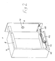
- a piece of furniture 2 according to the invention is shown in the form of a so-called maschiner Hees, a relative to a body 4 of the furniture between a in Fig. 1 shown retracted position and an extended position (see. Fig. 2 ) has movable extension 6.
- a relative to a body 4 of the furniture between a in Fig. 1 shown retracted position and an extended position (see. Fig. 2 ) has movable extension 6.
- To guide the extract 6 on the body 4 vertically spaced guide rail assemblies 8, 10 are provided.
- drive means For moving the extract 6 from the retracted position to the extended position, drive means are provided, which in this embodiment have a drive unit 14 arranged on the bottom 12 of the body 4.
- the drive unit 14 is formed in this embodiment as a linear drive and has an in Fig. 1 not shown, in the direction of the inner surface of the extract 6 movable plunger, which acts on the inner surface of the extract 6 loose.
- the basic structure of corresponding linear drives is generally known to the person skilled in the art and will therefore not be explained in more detail here.
- the furniture further has control means for controlling the drive unit 14, which according to the invention have a vibration switch 16 arranged on the pull-out in this embodiment.
- the vibration switch 16 is arranged in this embodiment behind a front panel of the drawer 6.
- signal transmission means are provided for wireless transmission of signals from the vibration switch 16 to the drive unit 14, which are assigned to the vibration switch 16 Radio transmitter and one of the drive unit 14 associated, received in a housing of the drive unit 14 have radio transmitter. In this embodiment, the signal transmission between the vibration switch 16 and the drive unit 14 thus takes place by radio.
- the power supply of the drive unit 14 via not shown power supply means.
- a replaceable battery accommodated in a housing of the vibration switch 16 is provided so that supply lines from the drive unit 14 or an external power supply to the vibration switch 16 are not required.
- a movement of the extract 6 from the extended position back to the retracted position takes place in this embodiment by hand.
- the extract 6 of the furniture 2 according to the invention is thus operable in a particularly simple and reliable manner, the overall aesthetic impression of the furniture 2 is not affected by the vibration switch 16, since this is arranged behind the front panel of the drawer 6. Since lines for connecting the vibration switch 16 to the drive unit 14 are not required in this embodiment, the assembly of the drive unit 14 and the vibration switch 16 on the drawer 6 and the body 4 of the cabinet 2 is particularly simple.
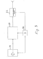
- Fig. 3 shows a block diagram of components of the control means of the furniture according to Fig. 2 ,
- the vibration switch 16 is in signal transmission connection with an evaluation and control processor 20, which in turn is in signal transmission connection with the vibration switch 16 associated radio transmitter 22.
- an evaluation and control processor 20 To supply voltage to the vibration switch 16, the evaluation and control processor 20 and the radio transmitter 22, a replaceable battery 24 is provided. Upon detection of a vibration, this transmits a signal to the evaluation and control processor 20, which then controls the radio transmitter 22 so that it sends a control signal to the drive unit 14, which then in the above with reference to Fig. 1 and 2 described manner moves the extract 6 in the extended position.
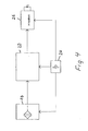
- Fig. 4 shows a block diagram of components of control means of a second embodiment of a furniture 2 according to the invention, which differs from the embodiment according to FIG Fig. 1 differs in that the transmission of signals between the vibration switch 16 and the drive unit 14 via infrared radiation, so that instead of the radio transmitter 22, an infrared transmitter 26 is provided.
- the drive unit 14 is accordingly assigned an infrared receiver.
Landscapes
- Drawers Of Furniture (AREA)
- Power-Operated Mechanisms For Wings (AREA)
- Selective Calling Equipment (AREA)
Description
Die Erfindung betrifft ein Möbel der im Oberbegriff des Anspruchs 1 genannten Art.The invention relates to a piece of furniture referred to in the preamble of claim 1 Art.
Derartige Möbel sind allgemein bekannt, beispielsweise durch
Durch
Der Erfindung liegt die Aufgabe zugrunde, ein weiteres Möbel der im Oberbegriff des Anspruchs 1 genannten Art anzugeben.The invention has for its object to provide a further piece of furniture mentioned in the preamble of claim 1.
Diese Aufgabe wird durch die im Anspruch 1 angegebene Lehre gelöst.This object is achieved by the teaching defined in claim 1.
Die erfindungsgemäße Lehre sieht vor, daß die Steuerungsmittel wenigstens einen an dem Auszug angeordneten Vibrationsschalter aufweisen und die Antriebsmittel in Abhängigkeit von Ausgangssignalen des Vibrationsschalters ansteuern. Derartige Vibrationsschalter, die auch als Vibrationssensoren bezeichnet werden, dienen zur hochempfindlichen Detektion von Erschütterungen. Sie können beispielsweise so aufgebaut sein, daß eine Quecksilberperle oder eine Kugel in einem Becher angeordnet ist und bereits geringste Bewegungen der Quecksilberperle oder der Kugel, die durch Erschütterungen hervorgerufen werden, dadurch detektiert werden, daß die Quecksilberperle oder die Kugel zwei elektrische Kontakte überbrückt. Auf diese Weise ist eine hochempfindliche Detektion von Erschütterungen ermöglicht.The teaching according to the invention provides that the control means have at least one vibration switch arranged on the extension and actuate the drive means in response to output signals of the vibration switch. Such vibration switches, which are also referred to as vibration sensors, are used for the highly sensitive detection of shocks. They may, for example, be constructed so that a bead of mercury or a ball is arranged in a cup and even slightest movements of the mercury bead or the ball, which are caused by vibrations, be detected by the fact that the mercury bead or the ball bridges two electrical contacts. In this way, a highly sensitive detection of vibrations is possible.
Um bei dem erfindungsgemäßen Möbel den Auszug in seine ausgezogene Position zu bewegen, erzeugt ein Benutzer im Bereich des Vibrationsschalters Erschütterungen, indem er beispielsweise gegen eine Blende klopft, hinter der der Vibrationsschalter angeordnet ist. Die hierbei entstehenden Erschütterungen werden von dem Vibrationsschalter detektiert, der daraufhin ein Ausgangssignal erzeugt und an die Steuerungsmittel überträgt. Die Steuerungsmittel steuern daraufhin die Antriebsmittel derart an, daß diese den Auszug in die ausgezogene Position bewegen. Auf diese Weise ist die Bedienung des erfindungsgemäßen Möbels besonders bequem gestaltet.In order to move the extract to its extended position in the furniture according to the invention, a user creates vibrations in the region of the vibration switch, for example, by knocking against a panel behind which the vibration switch is arranged. The resulting vibrations are detected by the vibration switch, which then generates an output signal and transmits it to the control means. The control means then control the drive means to move the drawer to the extended position. In this way, the operation of the furniture according to the invention is designed particularly convenient.
Eine unerwünschte Aktivierung der Antriebsmittel, beispielsweise durch Vibrationen, die von Trittschall herrühren, läßt sich dadurch vermeiden, daß die Empfindlichkeit des Vibrationsschalters entsprechend gewählt wird. Dies kann beispielsweise dadurch geschehen, daß ein Vibrationsschalter verwendet wird, dessen Empfindlichkeit so gewählt ist, daß er auf Vibrationen anspricht, die durch ein Klopfen in seiner unmittelbaren Nähe erzeugt werden, auf Vibrationen, die durch Trittschall oder Geräusche hervorgerufen werden, jedoch nicht anspricht. Es kann jedoch auch ein höherempfindlicher Vibrationsschalter verwendet werden, dessen Empfindlichkeit durch entsprechende Dämmittel herabgesetzt wird.An undesirable activation of the drive means, for example due to vibrations resulting from impact sound, can be avoided by the sensitivity of the vibration switch is selected accordingly. This can be done, for example, by that a vibration switch is used, the sensitivity of which is chosen so that it responds to vibrations that are produced by knocking in its immediate vicinity, to vibrations that are caused by impact sound or noise, but does not respond. However, it can also be used a more sensitive vibration switch whose sensitivity is reduced by appropriate Dämmittel.
Erfindungsgemäß können insbesondere miniaturisierte Vibrationsschalter verwendet werden, wie sie kommerziell beispielsweise von der Sensolute GmbH, D-76133 Karlsruhe (www.sensolute.com) unter der Bezeichnung "Mikro-Vibrationssensor", hergestellt werden. Derartige Vibrationsschalter verwenden anstelle einer Quecksilberkugel eine bewegliche Mikrokugel mit einem Durchmesser von beispielsweise 0,8 mm.According to the invention, in particular, miniaturized vibration switches can be used, as are commercially produced, for example, by Sensolute GmbH, D-76133 Karlsruhe (www.sensolute.com) under the name "micro-vibration sensor". Such vibration switches use a movable microsphere having a diameter of, for example, 0.8 mm instead of a mercury ball.
Form, Größe und Anzahl der Auszüge des erfindungsgemäßen Möbels sind innerhalb weiter Grenzen wählbar. Das erfindungsgemäße Möbel kann beispielsweise als Küchenschrank ausgebildet sein, bei dem der Auszug oder die Auszüge als Schublade ausgebildet ist bzw. sind. Das erfindungsgemäße Möbel kann jedoch auch als sogenannter Apothekerschrank ausgebildet sein, bei dem sich der Auszug über die gesamte Höhe des Möbels erstreckt.Shape, size and number of extracts of the furniture according to the invention can be selected within wide limits. The furniture according to the invention may be formed, for example, as a kitchen cabinet, in which the extract or the extracts is designed as a drawer or are. However, the furniture according to the invention may also be designed as a so-called apothecary cabinet in which the extract extends over the entire height of the furniture.
Erfindungsgemäß ist es grundsätzlich ausreichend, wenn die Antriebsmittel eine einzige Antriebseinheit, die beispielsweise und insbesondere als elektromotorische Antriebseinheit ausgebildet sein kann, aufweisen. Entsprechend den jeweiligen Anforderungen können jedoch auch zwei oder mehrere Antriebseinheiten vorgesehen sein.According to the invention, it is basically sufficient if the drive means have a single drive unit, which may be designed, for example, and in particular as an electromotive drive unit. However, according to the respective requirements, two or more drive units can also be provided.
Grundsätzlich kann der Vibrationsschalter an der vorderen, also dem Benutzer zugewandten Fläche des Auszuges angeordnet sein. Eine vorteilhafte Weiterbildung der erfindungsgemäßen Lehre sieht jedoch vor, daß der Vibrationsschalter hinter einer Frontblende des Auszuges angeordnet ist. Auf diese Weise ist der Vibrationsschalter von der Vorderseite, also der dem Benutzer zugewandten Seite, der Frontblende nicht sichtbar, so daß der ästhetische Gesamteindruck des Möbels durch den Vibrationsschalter nicht gestört ist.Basically, the vibration switch on the front, so the user facing surface of the extract be arranged. An advantageous development of the teaching of the invention, however, provides that the vibration switch is arranged behind a front panel of the extract. In this way, the vibration switch from the front, so the user-facing side of the front panel is not visible, so that the overall aesthetic impression of the furniture is not disturbed by the vibration switch.
Grundsätzlich kann die Übertragung von Steuerungssignalen von den Steuerungsmitteln zu den Antriebsmittel drahtgebunden erfolgen. Eine vorteilhafte Weiterbildung der erfindungsgemäßen Lehre sieht jedoch vor, daß Signalübertragungsmittel zur drahtlosen Übertragung von Signalen von dem Vibrationsschalter zu den Antriebsmitteln vorgesehen sind. Auf diese Weise ist eine Verdrahtung zwischen dem an dem Auszug angeordneten Vibrationsschalter und den an dem Korpus des Möbels angeordneten Antriebsmitteln nicht erforderlich, so daß bei dieser Ausführungsform die Antriebsmittel besonders einfach gestaltet und montierbar sind.In principle, the transmission of control signals from the control means to the drive means can be wired. An advantageous development of the teaching according to the invention, however, provides that signal transmission means are provided for the wireless transmission of signals from the vibration switch to the drive means. In this way, a wiring between the arranged on the extract vibration switch and arranged on the body of the furniture drive means is not required, so that in this embodiment, the drive means are particularly simple design and mountable.
Die Ausführungsform sieht vor, daß die Signalübertragungsmittel wenigstens einen dem Vibrationsschalter zugeordneten Funksender und wenigstens einen den Antriebsmitteln zugeordneten Funkempfänger aufweisen. Erfindungsgemäß werden Steuerungssignale von dem Vibrationsschalter zu den Antriebsmitteln per Funk übertragen.The embodiment provides that the signal transmission means comprise at least one radio transmitter associated with the radio transmitter and at least one of the drive means associated radio receiver. According to the invention, control signals are transmitted from the vibration switch to the drive means by radio.
Eine andere Weiterbildung der Ausführungsform mit den Signalübertragungsmitteln sieht vor, daß diese wenigstens einen dem Vibrationsschalter zugeordneten Infrarotsender und wenigstens einen den Antriebsmitteln zugeordneten Infrarotempfänger aufweisen. Bei dieser Ausführungsform erfolgt die Übertragung von Signalen von dem Vibrationsschalter zu den Antriebsmitteln per Infrarotstrahlung.Another embodiment of the embodiment with the signal transmission means provides that they have at least one infrared transmitter assigned to the vibration switch and at least one infrared receiver associated with the drive means. In this embodiment, the transmission of signals takes place from the vibration switch to the drive means by infrared radiation.
Eine andere vorteilhafte Weiterbildung der erfindungsgemäßen Lehre sieht vor, daß zur Spannungsversorgung des Vibrationsschalters wenigstens eine Batterie und/oder wenigstens ein Akkumulator vorgesehen ist. Auf diese Weise ist eine drahtgebundene Verbindung des Vibrationsschalters mit einer Spannungsquelle vermieden.Another advantageous development of the teaching of the invention provides that at least one battery and / or at least one accumulator is provided for supplying power to the vibration switch. In this way, a wired connection of the vibration switch with a voltage source is avoided.
Die Erfindung wird nachfolgend anhand der.beigefügten Zeichnung näher beschrieben, in der ein Ausführungsbeispiel eines erfindungsgemäßen Möbels dargestellt ist. Dabei bilden alle beanspruchten, beschriebenen und in der Zeichnung dargestellten Merkmale für sich genommen oder in beliebiger Kombination miteinander den Gegenstand der Erfindung, unabhängig von ihrer Zusammenfassung in den Schutzansprüchen sowie unabhängig von ihrer Beschreibung bzw. Darstellung in der Zeichnung.The invention will be described in more detail with reference to the attached drawing, in which an embodiment of a piece of furniture according to the invention is shown. All claimed, described and illustrated in the drawing features taken alone or in any combination with each other the subject of the invention, regardless of their summary in the claims and regardless of their description or representation in the drawing.
Es zeigt:
- Fig. 1
- eine schematische Perspektivansicht eines Ausführungsbeispiels eines erfindungsgemäßen Möbels in Form eines Apothekerschrankes, wobei der Auszug in der eingezogenen Position dargestellt ist,
- Fig. 2
- in gleicher Darstellung wie
Fig. 1 das Möbel gemäßFig. 1 , wobei der Auszug in der ausgezogenen Position dargestellt ist, - Fig. 3
- ein Blockschaltbild der Steuerungsmittel des Ausführungsbeispiels gemäß
Fig. 1 und - Fig. 4
- ein Blockschaltbild von Steuerungsmitteln eines zweiten Ausführungsbeispiels eines erfindungsgemäßen Möbels.
- Fig. 1
- 2 is a schematic perspective view of an exemplary embodiment of a piece of furniture according to the invention in the form of a pharmacy cabinet, wherein the extract is shown in the retracted position,
- Fig. 2
- in the same representation as
Fig. 1 according to the furnitureFig. 1 wherein the drawer is shown in the extended position, - Fig. 3
- a block diagram of the control means of the embodiment according to
Fig. 1 and - Fig. 4
- a block diagram of control means of a second embodiment of a piece of furniture according to the invention.
In den Figuren der Zeichnung sind gleiche bzw. sich entsprechende Bauteile mit den gleichen Bezugszeichen versehen.In the figures of the drawing, the same or corresponding components are provided with the same reference numerals.
In
Zum Bewegen des Auszuges 6 aus der eingezogenen Position in die ausgezogene Position sind Antriebsmittel vorgesehen, die bei diesem Ausführungsbeispiel eine an dem Boden 12 des Korpus 4 angeordnete Antriebseinheit 14 aufweisen. Die Antriebseinheit 14 ist bei diesem Ausführungsbeispiel als Linearantrieb ausgebildet und weist einen in
Das Möbel weist ferner Steuerungsmittel zur Ansteuerung der Antriebseinheit 14 auf, die erfindungsgemäß einen bei diesem Ausführungsbeispiel an dem Auszug angeordneten Vibrationsschalter 16 aufweisen. Der Vibrationsschalter 16 ist bei diesem Ausführungsbeispiel hinter einer Frontblende des Auszuges 6 angeordnet. Bei diesem Ausführungsbeispiel sind Signalübertragungsmittel zur drahtlosen Übertragung von Signalen von dem Vibrationsschalter 16 zu der Antriebseinheit 14 vorgesehen, die einen dem Vibrationsschalter 16 zugeordneten Funksender und einen der Antriebseinheit 14 zugeordneten, in einem Gehäuse der Antriebseinheit 14 aufgenommenen Funksender aufweisen. Bei diesem Ausführungsbeispiel erfolgt die Signalübertragung zwischen dem Vibrationsschalter 16 und der Antriebseinheit 14 somit per Funk. Die Spannungsversorgung der Antriebseinheit 14 erfolgt über nicht näher dargestellte Spannungsversorgungsmittel. Zur Spannungsversorgung des Vibrationsschalters 16 ist eine in einem Gehäuse des Vibrationsschalters 16 aufgenommene auswechselbare Batterie vorgesehen, so daß Zuleitungen von der Antriebseinheit 14 oder einer externen Spannungsversorgung zu dem Vibrationsschalter 16 nicht erforderlich sind.The furniture further has control means for controlling the
Die Funktionsweise des erfindungsgemäßen Möbels 2 ist wie folgt:The operation of the
Zum Bewegen des Auszuges 6 in die ausgezogene Position klopft ein Benutzer gegen die Frontblende des Auszuges 6. Auf die hierbei erzeugten Vibrationen spricht der Vibrationsschalter 16 an und erzeugt Signale zur Ansteuerung der Antriebseinheit 14, die per Funk zu dieser übertragen werden. Die Antriebseinheit 14 wird daraufhin so angesteuert, daß sich der in
Eine Bewegung des Auszuges 6 aus der ausgezogenen Position zurück in die eingezogene Position erfolgt bei diesem Ausführungsbeispiel von Hand.A movement of the
Der Auszug 6 des erfindungsgemäßen Möbels 2 ist damit auf besonders einfache und zuverlässige Weise betätigbar, wobei der ästhetische Gesamteindruck des Möbels 2 durch den Vibrationsschalter 16 nicht beeinträchtigt ist, da dieser hinter der Frontblende des Auszuges 6 angeordnet ist. Da Leitungen zur Verbindung des Vibrationsschalters 16 mit der Antriebseinheit 14 bei diesem Ausführungsbeispiel nicht erforderlich sind, ist die Montage der Antriebseinheit 14 und des Vibrationsschalters 16 an dem Auszug 6 bzw. dem Korpus 4 des Möbels 2 besonders einfach gestaltet.The
Claims (5)
- Piece of furniture, with a drawer, which can be moved by drive means relative to a carcass of the piece of furniture between a retracted position and a pulled-out position and with control means for activating the drive means, characterised in that the control means have at least one vibration switch (16) arranged on the drawer (6) and activate the drive means depending on output signals of the vibration switch (16) and in that signal transmission means are provided to wirelessly transmit signals from the vibration switch (16) to the drive means.
- Piece of furniture according to claim 1, characterised in that the vibration switch (16) is arranged behind a front panel of the drawer (6).
- Piece of furniture according to claim 1, characterised in that the signal transmission means have at least one radio transmitter (22) assigned to the vibration switch (16) and at least one radio receiver assigned to the drive means.
- Piece of furniture according to claim 1, characterised in that the signal transmission means have at least one infrared transmitter (26) assigned to the vibration switch and at least one infrared receiver assigned to the drive means.
- Piece of furniture according to any one of the preceding claims, characterised in that at least one battery (24) and/or at least one accumulator is provided for the voltage supply of the vibration switch (16).
Applications Claiming Priority (2)
| Application Number | Priority Date | Filing Date | Title |
|---|---|---|---|
| DE202007004338U DE202007004338U1 (en) | 2007-03-21 | 2007-03-21 | Furniture |
| PCT/EP2007/010861 WO2008113402A1 (en) | 2007-03-21 | 2007-12-12 | Piece of furniture |
Publications (2)
| Publication Number | Publication Date |
|---|---|
| EP2139362A1 EP2139362A1 (en) | 2010-01-06 |
| EP2139362B1 true EP2139362B1 (en) | 2014-06-04 |
Family
ID=39167044
Family Applications (1)
| Application Number | Title | Priority Date | Filing Date |
|---|---|---|---|
| EP07856609.8A Not-in-force EP2139362B1 (en) | 2007-03-21 | 2007-12-12 | Piece of furniture |
Country Status (4)
| Country | Link |
|---|---|
| EP (1) | EP2139362B1 (en) |
| DE (1) | DE202007004338U1 (en) |
| ES (1) | ES2498978T3 (en) |
| WO (1) | WO2008113402A1 (en) |
Families Citing this family (2)
| Publication number | Priority date | Publication date | Assignee | Title |
|---|---|---|---|---|
| DE102010012660A1 (en) | 2010-03-24 | 2011-09-29 | Linrot Holding Ag | Furniture i.e. pharmacist cabinet, has wireless transmitter and wireless receiver assigned to sensor and drive unit, respectively such that bidirectional signal transmission connection is formed between sensor and drive unit |
| DE202011005155U1 (en) | 2011-04-12 | 2012-07-13 | Linrot Holding Ag | Furniture |
Family Cites Families (23)
| Publication number | Priority date | Publication date | Assignee | Title |
|---|---|---|---|---|
| DE1069851B (en) | 1956-03-16 | 1959-11-26 | Saarbrücken Dr. Otto Alfred Becker | Device for pulling out and pushing in or out of a desk or the like arranged drawers, drawers, pulls or the like according to patent 1017 351 |
| DE8912722U1 (en) | 1989-10-27 | 1989-12-07 | Heinrich J. Kesseböhmer Draht- und Metallwarenfabrik, 4515 Bad Essen | Horizontally movable cabinet pull-out |
| DK0952255T3 (en) | 1998-04-20 | 2005-01-10 | Schweerbau Gmbh & Co Kg | Railroad vehicle with a rail milling device |
| DE50101806D1 (en) | 2000-02-14 | 2004-05-06 | Fulterer Gmbh Lustenau | Furniture with a motorized pull-out device |
| DE10105756A1 (en) | 2000-02-14 | 2001-08-16 | Fulterer Gmbh Lustenau | Control method for motorized extending device involves calibration run at reduced speed compared to normal to determine starting point for braking ramp for deployment and retraction |
| DE10036259A1 (en) | 2000-05-18 | 2001-11-22 | Westermann Kg | Waste bin built into drawer in unit is mounted on sliding rail, fixed rail and optionally intermediate rail and is moved outwards by motor which is mounted in unit |
| DE10037228A1 (en) | 2000-07-31 | 2002-02-21 | Rbs Netkom Gmbh | Cabinet security system and procedures |
| AT5058U1 (en) | 2001-05-11 | 2002-03-25 | Blum Gmbh Julius | HANDLE ARRANGEMENTS PARTICULARLY FOR FURNITURE |
| AT413632B (en) | 2001-12-27 | 2006-04-15 | Blum Gmbh Julius | MOVABLE FURNITURE |
| AT413631B (en) * | 2001-12-27 | 2006-04-15 | Blum Gmbh Julius | ARRANGEMENT WITH A MOVABLE FURNITURE, WITH A DRIVE UNIT AND WITH A CONTROL DEVICE |
| AT500362B1 (en) | 2002-06-27 | 2007-01-15 | Blum Gmbh Julius | ARRANGEMENT WITH A MOVABLE FURNITURE AND WITH A DRIVE UNIT |
| GB2398732A (en) | 2003-02-26 | 2004-09-01 | Jason Michael Chaplin | Powered opening and closing apparatus for drawers and doors |
| DE202004007170U1 (en) | 2003-05-19 | 2004-08-26 | Julius Blum Ges.M.B.H. | Compact damping system for servo driven furniture door or drawer has the motor connected to an electric load for electromotive braking in the final closing phase |
| AT7968U1 (en) | 2003-05-19 | 2005-12-15 | Blum Gmbh Julius | METHOD FOR DAMPING THE CLOSURE MOVEMENT OF A FURNITURE DRAWER OR FURNITURE DOOR |
| AT413933B (en) | 2003-05-19 | 2006-07-15 | Blum Gmbh Julius | FURNITURE WITH A MOVABLE FURNITURE |
| AT502574B1 (en) | 2003-05-19 | 2007-08-15 | Blum Gmbh Julius | FURNITURE WITH A MOVABLE FURNITURE |
| DE202004007168U1 (en) | 2003-05-19 | 2004-08-26 | Julius Blum Ges.M.B.H. | Servo drive to open and close a furniture door or drawer is activated by manual pressure or tension on the drawer or door to operate between end stops |
| AT413935B (en) | 2003-12-17 | 2006-07-15 | Blum Gmbh Julius | MOVABLE FURNITURE PART |
| DE202004008622U1 (en) | 2004-06-01 | 2004-08-05 | WECO Polstermöbel GmbH & Co. | Armchair with extending foot rest has a servo driven parallelogram lever support to slide a cushion from under the seat into a forward and raised position |
| AT503045B1 (en) | 2004-06-18 | 2008-01-15 | Blum Gmbh Julius | DEVICE FOR MOVING A MOVABLE FURNITURE PART |
| AT413633B (en) | 2004-08-16 | 2006-04-15 | Blum Gmbh Julius | RELEASE FOR MOVABLE FURNITURE PARTS |
| AT500722B1 (en) | 2004-08-16 | 2009-06-15 | Blum Gmbh Julius | BEARING ELEMENT FOR FASTENING IN A FURNITURE BASKET |
| DE202005006945U1 (en) | 2005-04-28 | 2006-05-04 | Grass Gmbh | Opening and closing system, especially for furniture parts |
-
2007
- 2007-03-21 DE DE202007004338U patent/DE202007004338U1/en not_active Expired - Lifetime
- 2007-12-12 ES ES07856609.8T patent/ES2498978T3/en active Active
- 2007-12-12 EP EP07856609.8A patent/EP2139362B1/en not_active Not-in-force
- 2007-12-12 WO PCT/EP2007/010861 patent/WO2008113402A1/en not_active Ceased
Also Published As
| Publication number | Publication date |
|---|---|
| ES2498978T3 (en) | 2014-09-26 |
| EP2139362A1 (en) | 2010-01-06 |
| DE202007004338U1 (en) | 2008-08-07 |
| WO2008113402A1 (en) | 2008-09-25 |
Similar Documents
| Publication | Publication Date | Title |
|---|---|---|
| EP2450228B1 (en) | Vehicle seat | |
| EP3390158B1 (en) | Motor vehicle control apparatus with retractable touch screen | |
| AT503248B1 (en) | ARRANGEMENT WITH ELECTRIC DRIVE UNITS FOR DRAWERS | |
| EP1891872A1 (en) | Device and process for detection of collisions for furniture | |
| DE202016105266U1 (en) | Electromotive furniture drive | |
| DE102014114170B4 (en) | Control element with safety mat | |
| DE102007003451B4 (en) | Cabinet with one or more excerpts | |
| EP2139362B1 (en) | Piece of furniture | |
| EP3781898B1 (en) | Sensor assembly, actuator, controller, electrically adjustable piece of furniture and method for operating an electrically adjustable piece of furniture | |
| DE102017104191A1 (en) | output device | |
| EP3309967A1 (en) | Capacitive switching device | |
| AT503033B1 (en) | DRIVE UNIT FOR MOVABLE FURNITURE PARTS | |
| EP2114202A2 (en) | Piece of furniture | |
| DE10342006B4 (en) | operating device | |
| WO2012159938A2 (en) | Arrangement of a switching unit that can be activated without contact in a front plate of a piece of furniture or of a domestic appliance | |
| CH672560A5 (en) | ||
| DE102012019718B4 (en) | Multifunction control device for operating a motor vehicle | |
| DE102010012660A1 (en) | Furniture i.e. pharmacist cabinet, has wireless transmitter and wireless receiver assigned to sensor and drive unit, respectively such that bidirectional signal transmission connection is formed between sensor and drive unit | |
| EP3170958B1 (en) | Container and method for triggering a drive device of the container | |
| AT503034B1 (en) | ARRANGEMENT WITH AT LEAST TWO DRIVEN FURNITURE PARTS | |
| EP3795958B1 (en) | Scale | |
| EP4168885B1 (en) | Feedback device for haptic feedback on a screen in a device, device and motor vehicle | |
| WO2018024301A1 (en) | Device for haptic signalling to a pedal | |
| AT505374B1 (en) | DRIVE DEVICE FOR A MOVABLE FURNITURE PART | |
| DE102016222131B4 (en) | Holding device for an interior of a motor vehicle |
Legal Events
| Date | Code | Title | Description |
|---|---|---|---|
| PUAI | Public reference made under article 153(3) epc to a published international application that has entered the european phase |
Free format text: ORIGINAL CODE: 0009012 |
|
| 17P | Request for examination filed |
Effective date: 20091021 |
|
| AK | Designated contracting states |
Kind code of ref document: A1 Designated state(s): AT BE BG CH CY CZ DE DK EE ES FI FR GB GR HU IE IS IT LI LT LU LV MC MT NL PL PT RO SE SI SK TR |
|
| DAX | Request for extension of the european patent (deleted) | ||
| 17Q | First examination report despatched |
Effective date: 20100831 |
|
| GRAP | Despatch of communication of intention to grant a patent |
Free format text: ORIGINAL CODE: EPIDOSNIGR1 |
|
| INTG | Intention to grant announced |
Effective date: 20131211 |
|
| GRAS | Grant fee paid |
Free format text: ORIGINAL CODE: EPIDOSNIGR3 |
|
| GRAA | (expected) grant |
Free format text: ORIGINAL CODE: 0009210 |
|
| AK | Designated contracting states |
Kind code of ref document: B1 Designated state(s): AT BE BG CH CY CZ DE DK EE ES FI FR GB GR HU IE IS IT LI LT LU LV MC MT NL PL PT RO SE SI SK TR |
|
| REG | Reference to a national code |
Ref country code: GB Ref legal event code: FG4D Free format text: NOT ENGLISH |
|
| REG | Reference to a national code |
Ref country code: CH Ref legal event code: EP |
|
| REG | Reference to a national code |
Ref country code: AT Ref legal event code: REF Ref document number: 670530 Country of ref document: AT Kind code of ref document: T Effective date: 20140615 |
|
| REG | Reference to a national code |
Ref country code: IE Ref legal event code: FG4D Free format text: LANGUAGE OF EP DOCUMENT: GERMAN |
|
| REG | Reference to a national code |
Ref country code: DE Ref legal event code: R096 Ref document number: 502007013177 Country of ref document: DE Effective date: 20140717 |
|
| REG | Reference to a national code |
Ref country code: ES Ref legal event code: FG2A Ref document number: 2498978 Country of ref document: ES Kind code of ref document: T3 Effective date: 20140926 |
|
| REG | Reference to a national code |
Ref country code: SE Ref legal event code: TRGR |
|
| RAP2 | Party data changed (patent owner data changed or rights of a patent transferred) |
Owner name: STABILUS GMBH |
|
| REG | Reference to a national code |
Ref country code: NL Ref legal event code: T3 |
|
| PG25 | Lapsed in a contracting state [announced via postgrant information from national office to epo] |
Ref country code: CY Free format text: LAPSE BECAUSE OF FAILURE TO SUBMIT A TRANSLATION OF THE DESCRIPTION OR TO PAY THE FEE WITHIN THE PRESCRIBED TIME-LIMIT Effective date: 20140604 Ref country code: GR Free format text: LAPSE BECAUSE OF FAILURE TO SUBMIT A TRANSLATION OF THE DESCRIPTION OR TO PAY THE FEE WITHIN THE PRESCRIBED TIME-LIMIT Effective date: 20140905 Ref country code: FI Free format text: LAPSE BECAUSE OF FAILURE TO SUBMIT A TRANSLATION OF THE DESCRIPTION OR TO PAY THE FEE WITHIN THE PRESCRIBED TIME-LIMIT Effective date: 20140604 Ref country code: LT Free format text: LAPSE BECAUSE OF FAILURE TO SUBMIT A TRANSLATION OF THE DESCRIPTION OR TO PAY THE FEE WITHIN THE PRESCRIBED TIME-LIMIT Effective date: 20140604 |
|
| REG | Reference to a national code |
Ref country code: DE Ref legal event code: R081 Ref document number: 502007013177 Country of ref document: DE Owner name: STABILUS GMBH, DE Free format text: FORMER OWNER: LINROT HOLDING AG, ZUERICH, CH Effective date: 20141006 |
|
| REG | Reference to a national code |
Ref country code: LT Ref legal event code: MG4D |
|
| PG25 | Lapsed in a contracting state [announced via postgrant information from national office to epo] |
Ref country code: LV Free format text: LAPSE BECAUSE OF FAILURE TO SUBMIT A TRANSLATION OF THE DESCRIPTION OR TO PAY THE FEE WITHIN THE PRESCRIBED TIME-LIMIT Effective date: 20140604 |
|
| PG25 | Lapsed in a contracting state [announced via postgrant information from national office to epo] |
Ref country code: PT Free format text: LAPSE BECAUSE OF FAILURE TO SUBMIT A TRANSLATION OF THE DESCRIPTION OR TO PAY THE FEE WITHIN THE PRESCRIBED TIME-LIMIT Effective date: 20141006 Ref country code: CZ Free format text: LAPSE BECAUSE OF FAILURE TO SUBMIT A TRANSLATION OF THE DESCRIPTION OR TO PAY THE FEE WITHIN THE PRESCRIBED TIME-LIMIT Effective date: 20140604 Ref country code: RO Free format text: LAPSE BECAUSE OF FAILURE TO SUBMIT A TRANSLATION OF THE DESCRIPTION OR TO PAY THE FEE WITHIN THE PRESCRIBED TIME-LIMIT Effective date: 20140604 Ref country code: EE Free format text: LAPSE BECAUSE OF FAILURE TO SUBMIT A TRANSLATION OF THE DESCRIPTION OR TO PAY THE FEE WITHIN THE PRESCRIBED TIME-LIMIT Effective date: 20140604 Ref country code: SK Free format text: LAPSE BECAUSE OF FAILURE TO SUBMIT A TRANSLATION OF THE DESCRIPTION OR TO PAY THE FEE WITHIN THE PRESCRIBED TIME-LIMIT Effective date: 20140604 |
|
| PG25 | Lapsed in a contracting state [announced via postgrant information from national office to epo] |
Ref country code: PL Free format text: LAPSE BECAUSE OF FAILURE TO SUBMIT A TRANSLATION OF THE DESCRIPTION OR TO PAY THE FEE WITHIN THE PRESCRIBED TIME-LIMIT Effective date: 20140604 Ref country code: IS Free format text: LAPSE BECAUSE OF FAILURE TO SUBMIT A TRANSLATION OF THE DESCRIPTION OR TO PAY THE FEE WITHIN THE PRESCRIBED TIME-LIMIT Effective date: 20141004 |
|
| REG | Reference to a national code |
Ref country code: DE Ref legal event code: R097 Ref document number: 502007013177 Country of ref document: DE |
|
| PLBE | No opposition filed within time limit |
Free format text: ORIGINAL CODE: 0009261 |
|
| STAA | Information on the status of an ep patent application or granted ep patent |
Free format text: STATUS: NO OPPOSITION FILED WITHIN TIME LIMIT |
|
| PG25 | Lapsed in a contracting state [announced via postgrant information from national office to epo] |
Ref country code: DK Free format text: LAPSE BECAUSE OF FAILURE TO SUBMIT A TRANSLATION OF THE DESCRIPTION OR TO PAY THE FEE WITHIN THE PRESCRIBED TIME-LIMIT Effective date: 20140604 |
|
| 26N | No opposition filed |
Effective date: 20150305 |
|
| REG | Reference to a national code |
Ref country code: DE Ref legal event code: R097 Ref document number: 502007013177 Country of ref document: DE Effective date: 20150305 |
|
| PG25 | Lapsed in a contracting state [announced via postgrant information from national office to epo] |
Ref country code: BE Free format text: LAPSE BECAUSE OF NON-PAYMENT OF DUE FEES Effective date: 20141231 |
|
| PG25 | Lapsed in a contracting state [announced via postgrant information from national office to epo] |
Ref country code: LU Free format text: LAPSE BECAUSE OF FAILURE TO SUBMIT A TRANSLATION OF THE DESCRIPTION OR TO PAY THE FEE WITHIN THE PRESCRIBED TIME-LIMIT Effective date: 20141212 Ref country code: SI Free format text: LAPSE BECAUSE OF FAILURE TO SUBMIT A TRANSLATION OF THE DESCRIPTION OR TO PAY THE FEE WITHIN THE PRESCRIBED TIME-LIMIT Effective date: 20140604 |
|
| REG | Reference to a national code |
Ref country code: CH Ref legal event code: PL |
|
| REG | Reference to a national code |
Ref country code: IE Ref legal event code: MM4A |
|
| PG25 | Lapsed in a contracting state [announced via postgrant information from national office to epo] |
Ref country code: CH Free format text: LAPSE BECAUSE OF NON-PAYMENT OF DUE FEES Effective date: 20141231 Ref country code: LI Free format text: LAPSE BECAUSE OF NON-PAYMENT OF DUE FEES Effective date: 20141231 Ref country code: IE Free format text: LAPSE BECAUSE OF NON-PAYMENT OF DUE FEES Effective date: 20141212 |
|
| REG | Reference to a national code |
Ref country code: FR Ref legal event code: PLFP Year of fee payment: 9 |
|
| REG | Reference to a national code |
Ref country code: AT Ref legal event code: MM01 Ref document number: 670530 Country of ref document: AT Kind code of ref document: T Effective date: 20141212 |
|
| PG25 | Lapsed in a contracting state [announced via postgrant information from national office to epo] |
Ref country code: AT Free format text: LAPSE BECAUSE OF NON-PAYMENT OF DUE FEES Effective date: 20141212 Ref country code: MC Free format text: LAPSE BECAUSE OF FAILURE TO SUBMIT A TRANSLATION OF THE DESCRIPTION OR TO PAY THE FEE WITHIN THE PRESCRIBED TIME-LIMIT Effective date: 20140604 Ref country code: BG Free format text: LAPSE BECAUSE OF FAILURE TO SUBMIT A TRANSLATION OF THE DESCRIPTION OR TO PAY THE FEE WITHIN THE PRESCRIBED TIME-LIMIT Effective date: 20140604 |
|
| PG25 | Lapsed in a contracting state [announced via postgrant information from national office to epo] |
Ref country code: HU Free format text: LAPSE BECAUSE OF FAILURE TO SUBMIT A TRANSLATION OF THE DESCRIPTION OR TO PAY THE FEE WITHIN THE PRESCRIBED TIME-LIMIT; INVALID AB INITIO Effective date: 20071212 Ref country code: MT Free format text: LAPSE BECAUSE OF FAILURE TO SUBMIT A TRANSLATION OF THE DESCRIPTION OR TO PAY THE FEE WITHIN THE PRESCRIBED TIME-LIMIT Effective date: 20140604 |
|
| REG | Reference to a national code |
Ref country code: DE Ref legal event code: R079 Ref document number: 502007013177 Country of ref document: DE Free format text: PREVIOUS MAIN CLASS: A47B0088040000 Ipc: A47B0088400000 |
|
| REG | Reference to a national code |
Ref country code: FR Ref legal event code: PLFP Year of fee payment: 10 |
|
| PGFP | Annual fee paid to national office [announced via postgrant information from national office to epo] |
Ref country code: TR Payment date: 20161128 Year of fee payment: 10 |
|
| REG | Reference to a national code |
Ref country code: FR Ref legal event code: PLFP Year of fee payment: 11 |
|
| PGFP | Annual fee paid to national office [announced via postgrant information from national office to epo] |
Ref country code: DE Payment date: 20191231 Year of fee payment: 13 |
|
| PGFP | Annual fee paid to national office [announced via postgrant information from national office to epo] |
Ref country code: SE Payment date: 20200121 Year of fee payment: 13 Ref country code: IT Payment date: 20200131 Year of fee payment: 13 Ref country code: GB Payment date: 20200124 Year of fee payment: 13 Ref country code: ES Payment date: 20200121 Year of fee payment: 13 Ref country code: NL Payment date: 20200121 Year of fee payment: 13 |
|
| PGFP | Annual fee paid to national office [announced via postgrant information from national office to epo] |
Ref country code: FR Payment date: 20200121 Year of fee payment: 13 |
|
| REG | Reference to a national code |
Ref country code: DE Ref legal event code: R119 Ref document number: 502007013177 Country of ref document: DE |
|
| REG | Reference to a national code |
Ref country code: SE Ref legal event code: EUG |
|
| REG | Reference to a national code |
Ref country code: NL Ref legal event code: MM Effective date: 20210101 |
|
| GBPC | Gb: european patent ceased through non-payment of renewal fee |
Effective date: 20201212 |
|
| PG25 | Lapsed in a contracting state [announced via postgrant information from national office to epo] |
Ref country code: NL Free format text: LAPSE BECAUSE OF NON-PAYMENT OF DUE FEES Effective date: 20210101 |
|
| PG25 | Lapsed in a contracting state [announced via postgrant information from national office to epo] |
Ref country code: IT Free format text: LAPSE BECAUSE OF NON-PAYMENT OF DUE FEES Effective date: 20201212 Ref country code: FR Free format text: LAPSE BECAUSE OF NON-PAYMENT OF DUE FEES Effective date: 20201231 |
|
| PG25 | Lapsed in a contracting state [announced via postgrant information from national office to epo] |
Ref country code: GB Free format text: LAPSE BECAUSE OF NON-PAYMENT OF DUE FEES Effective date: 20201212 Ref country code: DE Free format text: LAPSE BECAUSE OF NON-PAYMENT OF DUE FEES Effective date: 20210701 Ref country code: SE Free format text: LAPSE BECAUSE OF NON-PAYMENT OF DUE FEES Effective date: 20201213 |
|
| REG | Reference to a national code |
Ref country code: ES Ref legal event code: FD2A Effective date: 20220221 |
|
| PG25 | Lapsed in a contracting state [announced via postgrant information from national office to epo] |
Ref country code: ES Free format text: LAPSE BECAUSE OF NON-PAYMENT OF DUE FEES Effective date: 20201213 |
|
| PG25 | Lapsed in a contracting state [announced via postgrant information from national office to epo] |
Ref country code: TR Free format text: LAPSE BECAUSE OF NON-PAYMENT OF DUE FEES Effective date: 20171212 |