EP1526354A2 - Device and method for determining the angular position of a rotating element - Google Patents
Device and method for determining the angular position of a rotating element Download PDFInfo
- Publication number
- EP1526354A2 EP1526354A2 EP05001903A EP05001903A EP1526354A2 EP 1526354 A2 EP1526354 A2 EP 1526354A2 EP 05001903 A EP05001903 A EP 05001903A EP 05001903 A EP05001903 A EP 05001903A EP 1526354 A2 EP1526354 A2 EP 1526354A2
- Authority
- EP
- European Patent Office
- Prior art keywords
- signal
- output signal
- switching threshold
- sensor output
- sensor signal
- Prior art date
- Legal status (The legal status is an assumption and is not a legal conclusion. Google has not performed a legal analysis and makes no representation as to the accuracy of the status listed.)
- Granted
Links
- 238000000034 method Methods 0.000 title description 7
- 238000001514 detection method Methods 0.000 claims description 20
- 230000001419 dependent effect Effects 0.000 claims description 5
- 230000000630 rising effect Effects 0.000 claims description 5
- 238000003708 edge detection Methods 0.000 claims 1
- 230000001174 ascending effect Effects 0.000 abstract 1
- 239000003990 capacitor Substances 0.000 description 8
- 238000011161 development Methods 0.000 description 5
- 230000018109 developmental process Effects 0.000 description 5
- 238000011156 evaluation Methods 0.000 description 5
- 229920006395 saturated elastomer Polymers 0.000 description 4
- 238000012935 Averaging Methods 0.000 description 3
- 238000002485 combustion reaction Methods 0.000 description 3
- 230000001939 inductive effect Effects 0.000 description 3
- 238000013459 approach Methods 0.000 description 2
- 230000004069 differentiation Effects 0.000 description 2
- 230000001143 conditioned effect Effects 0.000 description 1
- 238000010586 diagram Methods 0.000 description 1
- 239000003344 environmental pollutant Substances 0.000 description 1
- 239000007789 gas Substances 0.000 description 1
- 238000009434 installation Methods 0.000 description 1
- 238000005259 measurement Methods 0.000 description 1
- 231100000719 pollutant Toxicity 0.000 description 1
Images


Classifications
-
- G—PHYSICS
- G01—MEASURING; TESTING
- G01D—MEASURING NOT SPECIALLY ADAPTED FOR A SPECIFIC VARIABLE; ARRANGEMENTS FOR MEASURING TWO OR MORE VARIABLES NOT COVERED IN A SINGLE OTHER SUBCLASS; TARIFF METERING APPARATUS; MEASURING OR TESTING NOT OTHERWISE PROVIDED FOR
- G01D5/00—Mechanical means for transferring the output of a sensing member; Means for converting the output of a sensing member to another variable where the form or nature of the sensing member does not constrain the means for converting; Transducers not specially adapted for a specific variable
- G01D5/12—Mechanical means for transferring the output of a sensing member; Means for converting the output of a sensing member to another variable where the form or nature of the sensing member does not constrain the means for converting; Transducers not specially adapted for a specific variable using electric or magnetic means
- G01D5/244—Mechanical means for transferring the output of a sensing member; Means for converting the output of a sensing member to another variable where the form or nature of the sensing member does not constrain the means for converting; Transducers not specially adapted for a specific variable using electric or magnetic means influencing characteristics of pulses or pulse trains; generating pulses or pulse trains
- G01D5/24471—Error correction
- G01D5/24476—Signal processing
-
- G—PHYSICS
- G01—MEASURING; TESTING
- G01D—MEASURING NOT SPECIALLY ADAPTED FOR A SPECIFIC VARIABLE; ARRANGEMENTS FOR MEASURING TWO OR MORE VARIABLES NOT COVERED IN A SINGLE OTHER SUBCLASS; TARIFF METERING APPARATUS; MEASURING OR TESTING NOT OTHERWISE PROVIDED FOR
- G01D5/00—Mechanical means for transferring the output of a sensing member; Means for converting the output of a sensing member to another variable where the form or nature of the sensing member does not constrain the means for converting; Transducers not specially adapted for a specific variable
- G01D5/12—Mechanical means for transferring the output of a sensing member; Means for converting the output of a sensing member to another variable where the form or nature of the sensing member does not constrain the means for converting; Transducers not specially adapted for a specific variable using electric or magnetic means
- G01D5/244—Mechanical means for transferring the output of a sensing member; Means for converting the output of a sensing member to another variable where the form or nature of the sensing member does not constrain the means for converting; Transducers not specially adapted for a specific variable using electric or magnetic means influencing characteristics of pulses or pulse trains; generating pulses or pulse trains
- G01D5/24471—Error correction
- G01D5/2448—Correction of gain, threshold, offset or phase control
Definitions
- the present invention relates to a device and a Method for detecting an angular position of a rotating Item, in particular for detecting the time at which the rotating object a predetermined angular position happens.
- Devices and methods of this kind are e.g. Used in automotive engines to ensure the exact angular position a crankshaft or a valve position to capture and based the detected position e.g. the combustion in a cylinder to control the car engine.
- the pollutant content in the Exhaust gases from such combustion depend critically on the ignition timing and thus on the accuracy with which the control position, by which the ignition is to be controlled, detected can be.
- Devices for detecting an angular position which in one such an environment can be used are numerous known. In essence, there are two groups of acquisition errors, which can occur on such a device. It On the one hand, these are constant angle errors, especially with Inaccuracies in the placement of such a device on the object whose angular position it is to be detected or the positioning of the components of the device to each other and on the other hand temporally changeable ones Errors that are stochastic, speed-dependent or thermally conditioned could be. These errors can have various causes. In current angular position sensing devices come mostly as sensors inductive magnetic sensors or Hall sensors used with an attached to the object to be detected Magnets interact.
- the second known technique is based on each of the signal peaks to detect the sensor output signal and based on this to the angular position of the object to be detected determine. It is assumed that the sensor output signal its maximum level - even if its value fluctuates - always at the same angular position of the detected Item will achieve.
- the problem that the output signals of the usual inductive magnetic sensors or Hall sensors are more or less sinusoidal and As a result, have very flat signal peaks, the very are sensitive to noise and interference.
- Object of the present invention is a device and a method for detecting an angular position of a rotating Subject to specify that a precise angle detection without automatic gain control and without detection allows the peaks of the sensor output signal and so on avoids the disadvantages of the above approaches.
- the level defines a range of values, the angular positions where the amount of the derivative of the Sensor output signal according to the angular position at least 10, 20, 30 or 50% of the maximum value of this derivative. If you e.g. assumes that the sensor output signal is sinusoidal varies with the angular position of the object, what for a variety of application situations apply, so are the areas where the level of the sensor output signal varies rapidly with the angular position, respectively in the environment the angular positions at which the sensor output signal crosses its own mean.
- the device of the invention expediently provided with an averaging circuit, from which an input receives the sensor output signal and an output is a signal representative of the threshold supplies.
- averaging circuit makes the invention Device independent of the installation situation or drift-induced shifts in the mean of the sensor output signal.
- the switching threshold is preferably by a defined first reference level, and the evaluation circuit provides the detection signal only when the level of the detection signal coming from above this first reference level but not when crossing from below.
- a second reference level can be defined, in which the evaluation circuit supplies the detection signal, when the level of the detection signal coming from below the crosses second reference level and does not deliver it when the Level of the detection signal coming from above the second reference level crosses.
- both reference levels simultaneously defined and different in the device according to the invention are, since this allows it in a simple way, one Generate hysteresis, the erroneous multiple acquisitions of predetermined angular position of the object due to signal noise suppressed in the course of one revolution of the object.
- the evaluation circuit which supplies the detection signal preferably comprises a comparator with two inputs, the at a first input the sensor output signal receives and the detection signal at its output provides when the levels the signals at its two entrances cross each other, and one Selection circuit for selectively supplying the first or of the second reference level to the second input of the comparator.
- the two are reference levels each on either side of an average of the sensor output selected. Knowing the functional relationship between the angular position of the object and the Sensor output signal can be the distance of the two reference levels be chosen from the mean value in each case so that they have two angular positions of the object in each case at the same distance from correspond to that angular position at which the sensor output signal crosses the mean. In the case of a sinusoidal Relationship between angular position and sensor output signal For this, the two reference levels must be the same in each case Distance above or below the mean value.
- the two reference levels between a central level and respectively one of two from the central level up or downwardly spaced levels changeable, and the first Reference level is at the central level when the sensor output signal the first reference level coming from above crosses and the second reference level is at the central Level when the sensor output signal is the second reference level Coming from below crosses.
- phase shifter circuit or a differentiation circuit for deriving the change of the reference levels from the sensor output signal.
- the one obtained with such a circuit differentiated sensor output signal can be used according to its sign either the first or the second reference level equal to the central level.
- the evaluation circuit at least one second comparator and one controlled by the comparator Comprise switches, wherein at an input of the comparator the Sensor output signal is present and at the other input of the comparator the one of the two reference levels is present, the same time is not applied to the first comparator, and the second comparator switches the switch when the levels of the two input signals of the second comparator intersect each other.
- the device is further provided with an amplitude detection circuit for detecting the amplitude of the sensor output signal Mistake.
- an amplitude detection circuit for detecting the amplitude of the sensor output signal Mistake.
- Such an amplitude detection circuit can be used to draw from it the two reference levels or, in the case that the reference levels are variable are to derive their spaced from the central level level.
- reference numeral 1 denotes a rotating object such as a sender wheel on a crankshaft one Internal combustion engine.
- the sender wheel 1 carries a magnet 2.
- the Detection device comprises a magnetic field sensor 3, e.g. an inductive sensor or a Hall sensor, which is a sensor output signal A supplies.
- the sensor output signal A is shown in FIG. 2 as a function of Rotation angle ⁇ of the encoder wheel shown and has a course similar a sine function, each period of the sine function corresponds to a revolution of the object.
- an amplifier 4 is connected to the output of the magnetic field sensor 3, which supplies an amplified sensor output signal B.
- the amplifier 2 may saturate at large amplitudes of the sensor output signal A. This is useful in the practice of the invention since it provides a signal to be processed with steep, well-detected zero crossings, but it is not necessary to the applicability of the invention.
- the amplified sensor output signal B is fed to a first input of a comparator 5.
- a reference level is applied, which is selected by a switch 6 between two voltage applied to its inputs reference levels E, F.
- the reference levels E, F are each chosen so that they intersect the curve of the amplified sensor output signal B at angular positions ⁇ 1 and ⁇ 3 , the1 lie in a same angular distance before or behind a zero crossing ⁇ 1 .
- the reference level C has the high value F.
- the output signal D of the comparator 5 tilts from zero to one, thus indicating the fact that the transmitter wheel is in the rotational position ⁇ 0 .
- the switch 6 is switched by the change of the output signal D, so that now the low reference level E is present at the second input of the comparator 5.
- Fig. 3 shows a first development of the device Fig. 1.
- the output of Amplifier 4 is connected to an averaging circuit, here in the form of an RC element of a resistor 7 and a Capacitor 8, in series with the output of the amplifier 4 with Connect ground.
- This center point 9 is connected to a first input of an adder 10, whose second input to the output of the switch. 6 is connected and whose output to the second input of the Comparator 5 is connected.
- the adder 10 superimposed so the respectively switched by the switch 6 reference level the mean voltage of the amplified sensor output signal B and makes the circuit so insensitive to drifting of the sensor 3, the amplifier 4 or any imbalances of the encoder wheel 1, which is a nonzero average of the sensor output A lead. This ensures that despite any such drifting the output signal D of the comparator 5 always at the same angular position of the encoder wheel 1 changes.
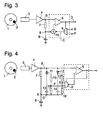
- FIG. 4 A further development is shown in FIG. 4.
- This embodiment differs from the two previously shown therein in that here the reference levels E, F are derived from the sensor output signal A.
- the device is provided with an amplitude detection circuit for the amplified sensor output signal B (saturated or non-saturated).
- the amplitude detection circuit is realized here in the form of two series circuits each comprising a diode 11, 12 and a capacitor 13, 14 which are connected on the one hand to the output of the amplifier 4 and on the other hand to the center point 9 of the RC element 7, 8.
- the diodes 11, 12 are each connected in antiparallel, so that via the diode 11, the capacitor 13 is charged, as long as the signal B has a potential below the average potential O at the center point 9, and the capacitor 14 is charged via the diode 12, when the level of the signal B is above the potential O of the center point 9.
- Two voltage dividers of resistors 15, 16 and 17, 18 are connected in parallel to the capacitors 13 and 14, respectively. Both voltage dividers share the voltages applied across the capacitors 13, 14 in the same ratio and supply them to the switch 6 as reference levels E and F, respectively.
- the circuit ensures that the reference levels E, F are each in a fixed, fixed by the division ratio of the voltage divider 15 to 18 ratio to the amplitude of the amplified sensor output signal B, so that even with changing amplitude of this signal is ensured that the device at equal angular positions ⁇ 0 (or ⁇ 3 ) of the encoder wheel 1 responds.
- the detection device shows a further development of the detection device according to the invention, which allows it at first View conflicting requirements with each other and to detect exactly that angular position at which the sensor output signal A crosses its mean, and nevertheless realize a hysteresis.
- Switching happens with the help of two switches 19, 20, which in turn turn controlled by the output signal K of an RS flip-flop 22 are.
- Set and reset input of the RS flip-flop 22 are each via a capacitor 23 to the outputs of comparators 24, 25 connected.
- the inputs of the comparator 24 are with the amplified sensor output signal B and the reference level, respectively E connected; those of the comparator 25 are reinforced with the Sensor output signal B and the reference level F connected.
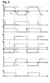
- the operation of this embodiment is based on the graphs Fig. 6 shown in more detail.
- the signal B is as with the of Figure 2 assumed identical; the immediate output signal A of the magnetic field sensor 3 is not shown in Fig. 6.
- the two comparators 24, 25 derive a logical one from B, respectively Signal L or M off.
- the signal L has the value one, if B is below the level F, and otherwise zero.
- the Signal M is one if B is above E level is, and otherwise the value zero.
- Leave the capacitors 23 one pulse each on a rising edge of the signals L, M to RS flip-flop to set or reset. These pulses are shown as dashed lines in the graph the signals L, M shown in Fig. 6.
- Negative impulses, each corresponding to the falling edges of the signals L, M are without influence on the RS flip-flop 22 and not in the figure shown; you can also by (not shown) Diodes are derived to ground.
- the flip-flop 22 switches the switches 19, 22 respectively just before a zero crossing ( ⁇ 2 or ⁇ 5) of the signal B. More specifically, the flip-flop 22 shifts shortly before a falling Zero crossing (at ⁇ 2) of the signal B, the output signal G. of the switch 20 from the level E to zero and the output signal H. of the switch 19 from level zero to F.
- the switch 6 passes the signal G as a signal J to the comparator 5. Consequently, up to the angle ⁇ 1, the signal J has the level E, is thus lower than the signal B, and the output signal D of the comparator 5 is constantly logic one.
- the signal G goes to zero at the angle ⁇ 1 , the signal J does the same, but the size ratios of the input signals of the comparator 5 do not change thereby, so that the output signal D of the comparator 5 keeps the level 1. Only at the zero crossing of the signal B, at ⁇ 2 , the proportions change, and the output signal D goes to zero. This leads to the switching of the switch 6, which now switches the signal H to the comparator 5.
- the switching threshold of the comparator is in time before the zero crossing of the signal B at ⁇ 5 back to zero, the position ⁇ 5 is detected correctly and shows up as the rising edge of the output signal D.
- FIG. 7 Another circuit variant, one with a zero crossing the signal B corresponding angular position of the encoder wheel 1 is accurately detected is shown in Fig. 7.
- a differentiation member 26 which is the time derivative dB / dt of the Signal B forms, and a trigger circuit 27 replaced.
- FIG. 8 Curves of signals in the circuit of FIG. 7 are shown in FIG. 8 is shown.
- Example assumed temporarily saturated course of the signal B results for dB / dt the course shown in the figure with alternating positive and negative intervals, separated through intervals at which the derivative disappears.
- the trigger circuit 27 forms the switches 19, 20 therefrom controlling signal K, which in each case in those angular intervals, in which the amplifier 4 is not saturated, depending on Sign of the derivative of B takes the value zero or one and in the intervening intervals in principle any Can accept values, since these intervals for the functioning the circuit are meaningless.
Landscapes
- Physics & Mathematics (AREA)
- General Physics & Mathematics (AREA)
- Engineering & Computer Science (AREA)
- Signal Processing (AREA)
- Transmission And Conversion Of Sensor Element Output (AREA)
- Indicating Or Recording The Presence, Absence, Or Direction Of Movement (AREA)
Abstract
Description
Die vorliegende Erfindung betrifft eine Vorrichtung und ein Verfahren zum Erfassen einer Winkelposition eines rotierenden Gegenstandes, insbesondere zum Erfassen des Zeitpunkts, an welchem der rotierende Gegenstand eine vorgegebene Winkelposition passiert. Vorrichtungen und Verfahren dieser Art werden z.B. in KFZ-Motoren eingesetzt, um die genaue Winkelstellung einer Kurbelwelle oder eine Ventilstellung zu erfassen und anhand der erfassten Stellung z.B. die Verbrennung in einem Zylinder des KFZ-Motors zu steuern. Der Schadstoffgehalt in den Abgasen einer solchen Verbrennung hängt kritisch vom Zündzeitpunkt und damit von der Genauigkeit ab, mit der die Regelposition, anhand derer die Zündung gesteuert werden soll, erfasst werden kann.The present invention relates to a device and a Method for detecting an angular position of a rotating Item, in particular for detecting the time at which the rotating object a predetermined angular position happens. Devices and methods of this kind are e.g. Used in automotive engines to ensure the exact angular position a crankshaft or a valve position to capture and based the detected position e.g. the combustion in a cylinder to control the car engine. The pollutant content in the Exhaust gases from such combustion depend critically on the ignition timing and thus on the accuracy with which the control position, by which the ignition is to be controlled, detected can be.
Vorrichtungen zum Erfassen einer Winkelposition, die in einem solchen Umfeld zur Anwendung kommen können, sind zahlreich bekannt. Im Wesentlichen gibt es zwei Gruppen von Erfassungsfehlern, die an einer solchen Vorrichtung auftreten können. Es sind dies zum Einen konstante Winkelfehler, die vor allem mit Ungenauigkeiten bei der Platzierung einer solchen Vorrichtung an dem Gegenstand, dessen Winkelposition es zu erfassen gilt, oder der Positionierung der Komponenten der Vorrichtung zueinander zusammenhängen, und andererseits zeitlich veränderliche Fehler, die stochastisch, drehzahlabhängig oder thermisch bedingt sein können. Diese Fehler können diverse Ursachen haben. In gegenwärtigen Winkelpositionserfassungsvorrichtungen kommen meist als Sensoren induktive Magnetsensoren oder Hall-Sensoren zum Einsatz, die mit einem am zu erfassenden Gegenstand angebrachten Magneten wechselwirken. Diese Sensoren liefern ein mit der Position des zu erfassenden Magneten stetig veränderliches Sensorausgangssignal, dessen Amplitude stark abhängig ist vom Abstand zwischen dem zu erfassenden Gegenstand und dem Sensor. Änderungen der Drehzahl des Gegenstandes verändern sowohl die Frequenz als auch die Form des Sensorausgangssignals, so dass im Allgemeinen aus dem Pegel des Sensorausgangssignals nicht eindeutig auf eine bestimmte Winkelposition rückgeschlossen werden kann. Um diese Probleme zu beheben, sind im wesentlichen zwei Techniken bekannt. Die erste beruht auf der Verwendung eines automatisch geregelten Verstärkers, dem das Sensorausgangssignal zugeführt wird und der aus diesem ein Signal mit einer fest vorgegebenen Amplitude erzeugt, bei dem dann angenommen wird, dass ein bestimmter Wert des verstärkungsgesteuerten Signals stets einer gleichen Winkelposition des zu erfassenden Gegenstandes entspricht. Dieses Verfahren hat den Nachteil, dass die Regelung auf Störungen oder Exzentrizität des Geberrades reagiert und in solchen Situationen zusätzliche Messfehler einführt.Devices for detecting an angular position, which in one such an environment can be used are numerous known. In essence, there are two groups of acquisition errors, which can occur on such a device. It On the one hand, these are constant angle errors, especially with Inaccuracies in the placement of such a device on the object whose angular position it is to be detected or the positioning of the components of the device to each other and on the other hand temporally changeable ones Errors that are stochastic, speed-dependent or thermally conditioned could be. These errors can have various causes. In current angular position sensing devices come mostly as sensors inductive magnetic sensors or Hall sensors used with an attached to the object to be detected Magnets interact. These sensors deliver with the position of the magnet to be detected continuously variable Sensor output signal whose amplitude is highly dependent is the distance between the object to be detected and the Sensor. Changes in the speed of the object change both the frequency as well as the shape of the sensor output signal, so that in general from the level of the sensor output signal not clearly deduced to a certain angular position can be. To fix these problems are in the essentially two techniques known. The first is based on the Use of an automatically controlled amplifier to which the Sensor output signal is supplied and from this one Signal generated at a fixed predetermined amplitude, in which then it is assumed that a certain value of the gain-controlled Signal always a same angular position corresponds to the object to be detected. This method has the disadvantage that the scheme on interference or eccentricity the transmitter wheel responds and in such situations additional Introduces measurement errors.
Die zweite bekannte Technik beruht darauf, jeweils die Signalspitzen des Sensorausgangssignals zu erfassen und anhand von diesen die Winkelposition des zu erfassenden Gegenstandes zu bestimmen. Dabei geht man davon aus, dass das Sensorausgangssignal seinen maximalen Pegel - auch wenn dessen Wert fluktuiert - immer bei der gleichen Winkelposition des zu erfassenden Gegenstandes erreichen wird. Hier ergibt sich das Problem, dass die Ausgangssignale der üblichen induktiven Magnetsensoren oder Hall-Sensoren mehr oder weniger sinusförmig sind und infolgedessen sehr flache Signalspitzen aufweisen, die sehr empfindlich gegen Rauschen und Störungen sind. The second known technique is based on each of the signal peaks to detect the sensor output signal and based on this to the angular position of the object to be detected determine. It is assumed that the sensor output signal its maximum level - even if its value fluctuates - always at the same angular position of the detected Item will achieve. Here's the problem that the output signals of the usual inductive magnetic sensors or Hall sensors are more or less sinusoidal and As a result, have very flat signal peaks, the very are sensitive to noise and interference.
Aufgabe der vorliegenden Erfindung ist, eine Vorrichtung und ein Verfahren zum Erfassen einer Winkelposition eines rotierenden Gegenstandes anzugeben, das eine präzise Winkelerfassung ohne automatische Verstärkungssteuerung und ohne Erfassung der Spitzen des Sensorausgangssignals ermöglicht und so die Nachteile der oben genannten Ansätze vermeidet.Object of the present invention is a device and a method for detecting an angular position of a rotating Subject to specify that a precise angle detection without automatic gain control and without detection allows the peaks of the sensor output signal and so on avoids the disadvantages of the above approaches.
Die Aufgabe wird erfindungsgemäß gelöst durch eine Vorrichtung
mit den Merkmalen des Anspruchs 1. Weiterbildungen der Erfindung
sind Gegenstand der Unteransprüche.The object is achieved by a device
with the features of
Während bei dem oben beschriebenen zweiten Ansatz als Bezugspunkt für die Auswertung des Sensorausgangssignals ausgerechnet derjenige Wertebereich gewählt wird, in welchem die Abhängigkeit des Sensorausgangssignals von der Winkelposition des zu erfassenden Gegenstandes ein Minimum erreicht, wird erfindungsgemäß für eine Schaltschwelle, bei deren Überschreitung festgestellt wird, dass der Gegenstand die zu erfassende Winkelposition hat, ein Wertebereich des Sensorausgangssignals gewählt, in welchem dieses schnell mit der Winkelposition variiert. Was eine schnelle Veränderung in Abhängigkeit von der Winkelposition ist, kann zwangsläufig nur mit Bezug auf die funktionsmäßige Abhängigkeit des Erfassungssignalpegels von der Winkelposition des zu erfassenden Gegenstandes definiert werden. So kann man z.B. als einen Wertebereich mit schneller Änderung des Pegels einen Wertebereich definieren, der Winkelpositionen entspricht, bei denen der Betrag der Ableitung des Sensorausgangssignals nach der Winkelposition wenigstens 10, 20, 30 oder 50 % des Maximalwerts dieser Ableitung beträgt. Wenn man z.B. annimmt, dass das Sensorausgangssignal sinusförmig mit der Winkelposition des Gegenstandes variiert, was für eine Vielzahl von Anwendungssituationen zutrifft, so liegen die Bereiche, in denen der Pegel des Sensorausgangssignals schnell mit der Winkelposition variiert, jeweils in der Umgebung der Winkelpositionen, an welchen das Sensorausgangssignal seinen eigenen Mittelwert kreuzt.While in the second approach described above as a reference point calculated for the evaluation of the sensor output signal that range of values is chosen in which the dependency of the sensor output from the angular position of the reaches a minimum to be detected, is inventively for a switching threshold, when exceeded it is determined that the object is the angular position to be detected has, a range of values of the sensor output signal in which this varies rapidly with the angular position. What a quick change depending on the Angular position is, inevitably, only with respect to the functional dependence of the detection signal level of defines the angular position of the object to be detected become. So you can, for example as a range of values with faster Changing the level define a range of values, the angular positions where the amount of the derivative of the Sensor output signal according to the angular position at least 10, 20, 30 or 50% of the maximum value of this derivative. If you e.g. assumes that the sensor output signal is sinusoidal varies with the angular position of the object, what for a variety of application situations apply, so are the areas where the level of the sensor output signal varies rapidly with the angular position, respectively in the environment the angular positions at which the sensor output signal crosses its own mean.
In der Nähe dieses Mittelwerts wird man daher zweckmäßigerweise die Schaltschwelle wählen.It is therefore expedient to be close to this mean value select the switching threshold.
Da der Mittelwert des Sensorausgangssignals für einen gegebenen Typ von Sensor je nach Umgebung, in der er eingesetzt wird, variieren kann, ist die erfindungsgemäße Vorrichtung zweckmäßigerweise mit einer Mittelwertbildungsschaltung versehen, von der ein Eingang das Sensorausgangssignal empfängt und ein Ausgang ein für die Schaltschwelle repräsentatives Signal liefert. Eine solche Mittelwertbildungsschaltung macht die erfindungsgemäße Vorrichtung unabhängig von durch die Einbausituation oder durch Driften verursachte Verschiebungen des Mittelwerts des Sensorausgangssignals.Since the average value of the sensor output signal for a given Type of sensor depending on the environment in which it is used is, can vary, is the device of the invention expediently provided with an averaging circuit, from which an input receives the sensor output signal and an output is a signal representative of the threshold supplies. Such averaging circuit makes the invention Device independent of the installation situation or drift-induced shifts in the mean of the sensor output signal.
Da das Sensorausgangssignal stetig mit der Winkelposition des Gegenstandes variiert, entspricht jeder Pegel des Sensorausgangssignals, der kein Extremwert ist, zwei verschiedenen Winkelpositionen des Gegenstandes. Um diese beiden Positionen voneinander zu unterscheiden und selektiv nur eine von ihnen zu erfassen, ist die Schaltschwelle vorzugsweise durch einen ersten Referenzpegel definiert, und die Auswertungsschaltung liefert das Erfassungssignal nur, wenn der Pegel des Erfassungssignals von oben kommend diesen ersten Referenzpegel kreuzt, nicht aber, wenn er ihn von unten kommend kreuzt. Analog kann natürlich ein zweiter Referenzpegel definiert sein, bei dem die Auswertungsschaltung das Erfassungssignal liefert, wenn der Pegel des Erfassungssignals von unten kommend den zweiten Referenzpegel kreuzt und es nicht liefert, wenn der Pegel des Erfassungssignals von oben kommend den zweiten Referenzpegel kreuzt.Since the sensor output signal is constantly at the angular position of the Varies, corresponds to each level of the sensor output signal, which is not an extreme value, two different angular positions of the object. To these two positions to distinguish from each other and selectively only one of them to detect, the switching threshold is preferably by a defined first reference level, and the evaluation circuit provides the detection signal only when the level of the detection signal coming from above this first reference level but not when crossing from below. Analogous Of course, a second reference level can be defined, in which the evaluation circuit supplies the detection signal, when the level of the detection signal coming from below the crosses second reference level and does not deliver it when the Level of the detection signal coming from above the second reference level crosses.
Besonders bevorzugt ist, dass beide Referenzpegel gleichzeitig in der erfindungsgemäßen Vorrichtung definiert und unterschiedlich sind, da dies es auf einfache Weise gestattet, eine Hysterese zu erzeugen, die fehlerhafte Mehrfacherfassungen der vorgegebenen Winkelposition des Gegenstandes aufgrund von Signalrauschen im Laufe einer Umdrehung des Gegenstandes unterdrückt.Particularly preferred is that both reference levels simultaneously defined and different in the device according to the invention are, since this allows it in a simple way, one Generate hysteresis, the erroneous multiple acquisitions of predetermined angular position of the object due to signal noise suppressed in the course of one revolution of the object.
Die Auswertungsschaltung, welche das Erfassungssignal liefert, umfasst vorzugsweise einen Komparator mit zwei Eingängen, der an einem ersten Eingang das Sensorausgangssignal empfängt und das Erfassungssignal an seinem Ausgang liefert, wenn die Pegel der Signale an seinen zwei Eingängen einander kreuzen, und eine Auswahlschaltung zum wahlweisen Zuführen des ersten oder des zweiten Referenzpegels zum zweiten Eingang des Komparators.The evaluation circuit which supplies the detection signal, preferably comprises a comparator with two inputs, the at a first input the sensor output signal receives and the detection signal at its output provides when the levels the signals at its two entrances cross each other, and one Selection circuit for selectively supplying the first or of the second reference level to the second input of the comparator.
Einer ersten, einfachen Ausgang zufolge, sind die zwei Referenzpegel jeweils beiderseits eines Mittelwerts des Sensorausgangssignals gewählt. In Kenntnis des funktionellen Zusammenhangs zwischen der Winkelposition des Gegenstandes und dem Sensorausgangssignal kann der Abstand der zwei Referenzpegel vom Mittelwert jeweils so gewählt werden, dass sie zwei Winkelpositionen des Gegenstandes jeweils in gleichem Abstand von derjenigen Winkelposition entsprechen, bei der das Sensorausgangssignal den Mittelwert kreuzt. Im Falle eines sinusförmigen Zusammenhangs zwischen Winkelposition und Sensorausgangssignal müssen hierfür die zwei Referenzpegel in jeweils gleichem Abstand oberhalb bzw. unterhalb des Mittelwertes liegen. According to a first, simple output, the two are reference levels each on either side of an average of the sensor output selected. Knowing the functional relationship between the angular position of the object and the Sensor output signal can be the distance of the two reference levels be chosen from the mean value in each case so that they have two angular positions of the object in each case at the same distance from correspond to that angular position at which the sensor output signal crosses the mean. In the case of a sinusoidal Relationship between angular position and sensor output signal For this, the two reference levels must be the same in each case Distance above or below the mean value.
Einer weiterentwickelten Ausgang der Erfindung zufolge sind die zwei Referenzpegel zwischen einem zentralen Pegel und jeweils einem von zwei von dem zentralen Pegel nach oben bzw. nach unten beabstandeten Pegeln veränderlich, und der erste Referenzpegel befindet sich am zentralen Pegel, wenn das Sensorausgangssignal den ersten Referenzpegel von oben kommend kreuzt, und der zweite Referenzpegel befindet sich am zentralen Pegel, wenn das Sensorausgangssignal den zweiten Referenzpegel von unten kommend kreuzt. So wird im einen wie im anderen Falle exakt der Durchgang des Sensorausgangssignals durch den zentralen Pegel erfasst und dennoch eine Hysterese realisiert.According to a further developed output of the invention the two reference levels between a central level and respectively one of two from the central level up or downwardly spaced levels changeable, and the first Reference level is at the central level when the sensor output signal the first reference level coming from above crosses and the second reference level is at the central Level when the sensor output signal is the second reference level Coming from below crosses. This is how it works in the one and the other Trap exactly the passage of the sensor output signal through detected the central level and yet realized a hysteresis.
Es gibt unterschiedliche Möglichkeiten, um zu gewährleisten, dass die beiden Referenzpegel sich jeweils zum richtigen Zeitpunkt auf dem zentralen Pegel befinden. Eine ist eine Phasenschieberschaltung oder eine Differentiationsschaltung (wobei im Falle eines sinusförmigen Zusammenhangs zwischen Winkelposition und Sensorausgangssignal zwischen beiden kein Unterschied besteht) zum Ableiten der Veränderung der Referenzpegel vom Sensorausgangssignal. Das mit einer solchen Schaltung erhaltene differenzierte Sensorausgangssignal kann genutzt werden, um je nach seinem Vorzeichen entweder den ersten oder den zweiten Referenzpegel gleich dem zentralen Pegel zu machen.There are different ways to ensure that the two reference levels are each at the right time located at the central level. One is a phase shifter circuit or a differentiation circuit (where in the case of a sinusoidal relationship between angular position and sensor output between both no difference exists) for deriving the change of the reference levels from the sensor output signal. The one obtained with such a circuit differentiated sensor output signal can be used according to its sign either the first or the second reference level equal to the central level.
Alternativ kann die Auswertungsschaltung wenigstens einen zweiten Komparator und einen von dem Komparator gesteuerten Schalter umfassen, wobei an einem Eingang des Komparators das Sensorausgangssignal anliegt und am anderen Eingang des Komparators derjenige der zwei Referenzpegel anliegt, der gleichzeitig nicht am ersten Komparator anliegt, und der zweite Komparator schaltet den Schalter um, wenn die Pegel der zwei Eingangssignale des zweiten Komparators einander kreuzen. Alternatively, the evaluation circuit at least one second comparator and one controlled by the comparator Comprise switches, wherein at an input of the comparator the Sensor output signal is present and at the other input of the comparator the one of the two reference levels is present, the same time is not applied to the first comparator, and the second comparator switches the switch when the levels of the two input signals of the second comparator intersect each other.
Vorzugsweise ist die Vorrichtung ferner mit einer Amplitudenerfassungsschaltung zum Erfassen der Amplitude des Sensorausgangssignals versehen. Eine solche Amplitudenerfassungsschaltung kann insbesondere genutzt werden, um von ihr die zwei Referenzpegel oder, in dem Fall, dass die Referenzpegel variabel sind, deren von dem zentralen Pegel beabstandete Pegel abzuleiten.Preferably, the device is further provided with an amplitude detection circuit for detecting the amplitude of the sensor output signal Mistake. Such an amplitude detection circuit In particular, it can be used to draw from it the two reference levels or, in the case that the reference levels are variable are to derive their spaced from the central level level.
Weitere Merkmale und Vorteile der Erfindung ergeben sich aus der nachfolgenden Beschreibung von Ausführungsbeispielen mit Bezug auf die beigefügten Figuren. Es zeigen:
- Fig. 1
- ein Blockdiagramm einer ersten Ausgestaltung einer erfindungsgemäßen Vorrichtung zum Erfassen einer Winkelposition;
- Fig. 2
- Signalverläufe an verschiedenen Punkten der Schaltung aus Fig. 1;
- Fig. 3
- eine zweite, weiterentwickelte Ausgestaltung der erfindungsgemäßen Vorrichtung;
- Fig. 4
- eine dritte, weiterentwickelte Ausgestaltung der Vorrichtung;
- Fig. 5
- eine abermals weiterentwickelte vierte Ausgestaltung der Vorrichtung;
- Fig. 6
- Signalverläufe an verschiedenen Punkten der Schaltung aus Fig. 5;
- Fig. 7
- eine fünfte Ausgestaltung der Vorrichtung; und
- Fig. 8
- Signalverläufe an verschiedenen Punkten der Schaltung aus Fig. 7.
- Fig. 1
- a block diagram of a first embodiment of an inventive device for detecting an angular position;
- Fig. 2
- Waveforms at various points of the circuit of Fig. 1;
- Fig. 3
- a second, further developed embodiment of the device according to the invention;
- Fig. 4
- a third, further developed embodiment of the device;
- Fig. 5
- a further developed fourth embodiment of the device;
- Fig. 6
- Waveforms at various points of the circuit of Fig. 5;
- Fig. 7
- a fifth embodiment of the device; and
- Fig. 8
- Signal curves at various points of the circuit of FIG. 7.
In Fig. 1 bezeichnet das Bezugszeichen 1 einen rotierenden Gegenstand
wie etwa ein Geberrad an einer Kurbelwelle einer
Brennkraftmaschine. Das Geberrad 1 trägt einen Magneten 2. Die
Erfassungsvorrichtung umfasst einen Magnetfeldsensor 3, z.B.
einen induktiven Sensor oder einen Hall-Sensor, der ein Sensorausgangssignal
A liefert.In Fig. 1,
Das Sensorausgangssignal A ist in Fig. 2 als Funktion des Drehwinkels des Geberrades gezeigt und hat einen Verlauf ähnlich einer Sinusfunktion, wobei jede Periode der Sinusfunktion einer Umdrehung des Gegenstandes entspricht.The sensor output signal A is shown in FIG. 2 as a function of Rotation angle of the encoder wheel shown and has a course similar a sine function, each period of the sine function corresponds to a revolution of the object.
An den Ausgang des Magnetfeldsensors 3 ist ein Verstärker 4
angeschlossen, der ein verstärktes Sensorausgangssignal B liefert.
Wie in Fig. 2 gezeigt, kann der Verstärker 2 bei großen
Amplituden des Sensorausgangssignals A in Sättigung gehen.
Dies ist für die Anwendung der Erfindung nützlich, da auf diese
Weise ein weiterzuverarbeitendes Signal mit steilen, gut zu
erfassenden Nulldurchgängen erhalten wird, es ist jedoch für
die Anwendbarkeit der Erfindung nicht erforderlich.To the output of the
This is useful in the practice of the invention since it provides a signal to be processed with steep, well-detected zero crossings, but it is not necessary to the applicability of the invention.
Das verstärkte Sensorausgangssignal B ist einem ersten Eingang
eines Komparators 5 zugeführt. An den zweiten Eingang des Komparators
5 ist ein Referenzpegel angelegt, der durch einen
Schalter 6 zwischen zwei an dessen Eingängen anliegenden Referenzpegeln
E, F ausgewählt ist. Die Referenzpegel E, F sind
jeweils so gewählt, dass sie die Kurve des verstärkten Sensorausgangssignals
B an Winkelpositionen 1 bzw. 3 schneiden, die1
in einem gleichen Winkelabstand vor bzw. hinter einem Nulldurchgang
1 liegen. Am Zeitursprung in Fig. 2, der willkürlich
so gewählt ist, dass dort das Signal B den Wert Null hat, hat
der Referenzpegel C den hohen Wert F. Der Komparator 5 liefert
das Ausgangssignal D=0. Wenn bei einem Drehwinkel 0 der Wert
des Signals B den Pegel F von unten kreuzt, kippt das Ausgangssignal
D des Komparators 5 von Null auf Eins und zeigt so
die Tatsache an, dass sich das Geberrad in der Drehposition 0
befindet. Gleichzeitig wird durch die Änderung des Ausgangssignals
D der Schalter 6 umgeschaltet, so dass nun der niedrige
Referenzpegel E am zweiten Eingang des Komparators 5 anliegt.
Am Ausgangssignals D des Komparators 5 ändert dies zunächst
nichts. Erst bei der Drehposition 3, wenn das Signal B
unter den niedrigen Referenzpegel E abfällt, geht das Ausgangssignal
D des Komparators 5 auf Null zurück, der Schalter
6 wird erneut umgeschaltet, und der Referenzpegel F liegt wieder
am zweiten Eingang des Komparators an. Wenn das Signal B
wieder über den Pegel F hinaus anwächst, ist ein Betriebszyklus
der Vorrichtung abgelaufen. Da die erfindungsgemäße Vorrichtung
auf schnelle Änderungen des Sensorausgangssignals A
anspricht, ist eine genaue Bestimmung des Zeitpunkts möglich,
an dem sich das Geberrad in der Stellung 0 (oder 3) befindet.The amplified sensor output signal B is fed to a first input of a
Fig. 3 zeigt eine erste Weiterentwicklung der Vorrichtung aus
Fig. 1. Bei dieser Weiterentwicklung ist an den Ausgang des
Verstärkers 4 eine Mittelwertbildungsschaltung angeschlossen,
hier in Form eines RC-Gliedes aus einem Widerstand 7 und einem
Kondensator 8, die in Reihe den Ausgang des Verstärkers 4 mit
Masse verbinden. Das Potential, das sich während des Betriebs
der Schaltung an einem Mittenpunkt 9 zwischen dem Widerstand
und dem Komparator einstellt, entspricht bei geeigneter Auswahl
der Zeitkonstante des RC-Gliedes der mittleren Spannung
des verstärkten Sensorausgangssignals B. Dieser Mittenpunkt 9
ist an einen ersten Eingang eines Addiergliedes 10 angeschlossen,
dessen zweiter Eingang mit dem Ausgang des Schalters 6
verbunden ist und dessen Ausgang mit dem zweiten Eingang des
Komparators 5 verbunden ist. Das Addierglied 10 überlagert so
dem jeweils vom Schalter 6 durchgeschalteten Referenzpegel die
mittlere Spannung des verstärkten Sensorausgangssignals B und
macht die Schaltung so unempfindlich gegen Driften des Sensors
3, des Verstärkers 4 oder eventuelle Unwuchten des Geberrades
1, die zu einem von Null abweichenden Mittelwert des Sensorausgangssignals
A führen. So ist gewährleistet, dass trotz eventueller
derartiger Driften das Ausgangssignal D des Komparators
5 stets bei der gleichen Winkelposition des Geberrades
1 sich ändert.Fig. 3 shows a first development of the device
Fig. 1. In this development is connected to the output of
Eine erneute Weiterentwicklung ist in Fig. 4 gezeigt. Diese
Ausgestaltung unterscheidet sich von den zwei zuvor gezeigten
darin, dass hier die Referenzpegel E, F vom Sensorausgangssignal
A abgeleitet werden. Zu diesem Zweck ist die Vorrichtung
mit einer Amplitudenerfassungsschaltung für das (gesättigte
oder nichtgesättigte) verstärkte Sensorausgangssignal B ausgestattet.
Die Amplitudenerfassungsschaltung ist hier realisiert
in Form von zwei Reihenschaltungen aus jeweils einer Diode
11, 12 und einem Kondensator 13, 14, die einerseits mit
dem Ausgang des Verstärkers 4 und andererseits mit dem Mittenpunkt
9 des RC-Gliedes 7, 8 verbunden sind. Die Dioden 11, 12
sind jeweils antiparallel geschaltet, so dass über die Diode
11 der Kondensator 13 geladen wird, solange das Signal B ein
Potential unterhalb des gemittelten Potentials O am Mittenpunkt
9 hat, und der Kondensator 14 über die Diode 12 geladen
wird, wenn der Pegel des Signals B über dem Potential O des
Mittenpunktes 9 liegt. Zwei Spannungsteiler aus Widerständen
15, 16 bzw. 17, 18 sind jeweils zu den Kondensatoren 13 bzw.
14 parallel geschaltet. Beide Spannungsteiler teilen die über
den Kondensatoren 13, 14 anliegenden Spannungen in gleichem
Verhältnis und führen sie als Referenzpegel E bzw. F dem
Schalter 6 zu. Durch die Schaltung ist gewährleistet, dass die
Referenzpegel E, F jeweils in einem festen, durch das Teilungsverhältnis
der Spannungsteiler 15 bis 18 festgelegten
Verhältnis zur Amplitude des verstärkten Sensorausgangssignals
B stehen, so dass auch bei wechselnder Amplitude dieses Signals
gewährleistet ist, dass die Vorrichtung bei gleichen Winkelpositionen
0 (bzw. 3) des Geberrades 1 anspricht.A further development is shown in FIG. 4. This embodiment differs from the two previously shown therein in that here the reference levels E, F are derived from the sensor output signal A. For this purpose, the device is provided with an amplitude detection circuit for the amplified sensor output signal B (saturated or non-saturated). The amplitude detection circuit is realized here in the form of two series circuits each comprising a
Bei den bisher betrachteten Ausgestaltungen zwingt die Notwendigkeit,
eine Hysterese zu implementieren, dazu, unterschiedliche
Referenzpegel für das Umschalten des Ausgangssignals D
auf Null bzw. auf Eins zu wählen. Es wäre wünschenswert, diese
Referenzpegel möglichst nahe beim Mittelwert 0 von B zu wählen,
denn je näher sie dem Mittelwert O sind, um so kleiner
sind Erfassungsfehler, die sich bei wechselnden Drehgeschwindigkeiten
des Geberrades 1 aus der Abhängigkeit der Amplitude
von A von dieser Drehgeschwindigkeit ergeben können. Je geringer
man jedoch die Differenz zwischen den zwei Referenzpegeln
macht, um so größer ist die Gefahr, dass ein Rauschanteil im
Sensorausgangssignal A zu Erfassungsfehlern führt, bei denen
die Vorrichtung zu früh oder zu spät anspricht.In the embodiments considered so far, the necessity of
to implement a hysteresis, in addition, different
Reference level for switching the output signal D.
to select zero or one. It would be desirable to do this
To choose the reference level as close to the
Fig. 5 zeigt eine Weiterentwicklung der erfindungsgemäßen Erfassungsvorrichtung,
die es erlaubt, diese sich auf den ersten
Blick widersprechenden Anforderungen miteinander zu vereinbaren
und exakt diejenige Winkelstellung zu erfassen, bei der
das Sensorausgangssignal A seinen Mittelwert kreuzt, und
trotzdem eine Hysterese zu realisieren. Bei dieser Ausgestaltung
sind die dem Schalter 6 zugeführten Referenzpotentiale,
hier mit H, G bezeichnet, nicht konstant bzw. bis auf die bereits
erwähnten Driften konstant, sondern sie werden im Laufe
jeder Umdrehung des Geberrades 1 zwischen dem durch das RC-Glied
7, 8 erhaltenen mittleren Potential 0 des verstärkten
Sensorausgangssignals B und den von der Amplitudenerfassungsschaltung
11 bis 18 gelieferten, von dem mittleren Potential O
jeweils um einen gleichen Betrag nach oben bzw. unten
beabstandeten Potential E, F umgeschaltet. Die Umschaltung geschieht
mit Hilfe zweier Schalter 19, 20, die ihrerseits wiederum
durch das Ausgangssignal K eines RS-Flipflops 22 gesteuert
sind. Setz- und Rücksetzeingang des RS-Flipflops 22 sind
jeweils über einen Kondensator 23 mit den Ausgängen von Komparatoren
24, 25 verbunden. Die Eingänge des Komparators 24 sind
mit dem verstärkten Sensorausgangssignal B bzw. dem Referenzpegel
E beschaltet; die des Komparators 25 sind mit dem verstärkten
Sensorausgangssignal B bzw. dem Referenzpegel F beschaltet.5 shows a further development of the detection device according to the invention,
which allows it at first
View conflicting requirements with each other
and to detect exactly that angular position at which
the sensor output signal A crosses its mean, and
nevertheless realize a hysteresis. In this embodiment
are the reference potentials supplied to the
Die Arbeitsweise dieser Ausgestaltung wird anhand der Graphen
der Fig. 6 genauer dargestellt. Das Signal B ist als mit dem
der Fig. 2 identisch angenommen; das unmittelbare Ausgangssignal
A des Magnetfeldsensors 3 ist in Fig. 6 nicht dargestellt.
Die zwei Komparatoren 24, 25 leiten von B jeweils ein logisches
Signal L bzw. M ab. Das Signal L hat den Wert Eins, wenn
B unterhalb des Pegels F liegt, und sonst den Wert Null. Das
Signal M hat den Wert Eins, wenn B oberhalb des Pegels E
liegt, und sonst den Wert Null. Die Kondensatoren 23 lassen
jeweils einen Impuls an einer ansteigenden Flanke der Signale
L, M zum RS-Flipflop durch, um dieses zu setzen oder rückzusetzen.
Diese Impulse sind als gestrichelte Linien in den Graphen
der Signale L, M in Fig. 6 dargestellt. Negative Impulse,
die jeweils den abfallenden Flanken der Signale L, M entsprechen,
sind ohne Einfluss auf das RS-Flipflop 22 und nicht in
der Figur gezeigt; sie können auch durch (nicht dargestellte)
Dioden nach Masse abgeleitet werden. The operation of this embodiment is based on the graphs
Fig. 6 shown in more detail. The signal B is as with the
of Figure 2 assumed identical; the immediate output signal
A of the
Wie man am Verlauf des Ausgangssignals K des Flipflops 22 erkennt,
wird dieses jeweils durch eine ansteigende Flanke des
Signals L bei der Winkelposition 1 gesetzt und durch eine abfallende
Flanke des Signals M bei der Winkelposition 4 rückgesetzt.
Das Flipflop 22 schaltet somit die Schalter 19, 22 jeweils
kurz vor einem Nulldurchgang (2 oder 5) des Signals B.
Genauer gesagt schaltet das Flipflop 22 kurz vor einem abfallenden
Nulldurchgang (bei 2) des Signals B das Ausgangssignal G
des Schalters 20 vom Pegel E auf Null und das Ausgangssignal H
des Schalters 19 vom Pegel Null auf F um.As can be seen from the course of the output signal K of the flip-
Am Ursprung der Graphen, bei =0, lässt der Schalter 6 das Signal
G als Signal J zum Komparator 5 durch. Folglich hat bis
zum Winkel 1 das Signal J den Pegel E, ist somit niedriger als
das Signal B, und das Ausgangssignal D des Komparators 5 ist
konstant logisch Eins. Wenn am Winkel 1 das Signal G auf Null
geht, tut das Signal J das gleiche, die Größenverhältnisse der
Eingangssignale des Komparators 5 ändern sich dadurch jedoch
nicht, so dass das Ausgangssignal D des Komparators 5 den Pegel
1 behält. Erst beim Nulldurchgang des Signals B, bei 2,
ändern sich die Größenverhältnisse, und das Ausgangssignal D
geht auf Null. Dies führt zur Umschaltung des Schalters 6, der
nun das Signal H zum Komparator 5 durchschaltet. Der damit
verbundene Pegelanstieg des Signals J auf F verändert das Ausgangssignal
D nicht, dieses bleibt Null, aber es wird eine
Hysterese dahingehend erreicht, dass eine Störung des Signals
B wenigstens die Amplitude F haben muss, um zu einem erneuten
Kippen des Ausgangssignals D zu führen.At the origin of the graphs, at = 0, the
Wenn am Winkel 4 das Signal B wieder über den Pegel E ansteigt,
so wird das Flipflop 22 rückgesetzt, und das Signal G
geht von Null auf E, und die Signale H, J gehen von F auf
Null. Somit liegt die Schaltschwelle des Komparators rechtzeitig
vor dem Nulldurchgang des Signals B bei 5 wieder auf Null,
die Position 5 wird korrekt erfasst und zeigt sich als ansteigende
Flanke des Ausgangssignals D.When at the angle 4, the signal B again rises above the level E, the flip-
Eine andere Schaltungsvariante, mit der eine einem Nulldurchgang
des Signals B entsprechende Winkelposition des Geberrades
1 exakt erfasst werden ist, ist in Fig. 7 gezeigt. Hier sind
die Komparatoren 24, 25 und das Flipflop 22 durch ein Differentiationsglied
26, das die zeitliche Ableitung dB/dt des
Signals B bildet, und eine Triggerschaltung 27 ersetzt.Another circuit variant, one with a zero crossing
the signal B corresponding angular position of the
Verläufe von Signalen in der Schaltung der Fig. 7 sind in Fig.
8 dargestellt. Bei dem in der vorliegenden Beschreibung als
Beispiel angenommenen zeitweilig gesättigten Verlauf des Signals
B ergibt sich für dB/dt der in der Fig. gezeigte Verlauf
mit abwechselnden positiven und negativen Intervallen, getrennt
durch Intervalle, in denen die Ableitung verschwindet.
Die Triggerschaltung 27 formt daraus das die Schalter 19, 20
steuernde Signal K, das jeweils in denjenigen Winkelintervallen,
in denen der Verstärker 4 nicht gesättigt ist, je nach
Vorzeichen der Ableitung von B den Wert Null oder Eins annimmt
und in den dazwischenliegenden Intervallen im Prinzip beliebige
Werte annehmen kann, da diese Intervalle für die Funktionsweise
der Schaltung ohne Bedeutung sind.Curves of signals in the circuit of FIG. 7 are shown in FIG.
8 is shown. In the present description as
Example assumed temporarily saturated course of the signal
B results for dB / dt the course shown in the figure
with alternating positive and negative intervals, separated
through intervals at which the derivative disappears.
The
Aus der Form des Schaltsignals K ergibt sich für die Ausgangssignale
H, G der Schalter 19, 20 bei Nichtsättigung des Verstärkers
4 die in Fig. 8 als durchgezogene Linien dargestellten
Pegel E oder Null bzw. Null oder F. Wie bei der Ausgestaltung
der Fig. 5, liegt während einer abfallenden Flanke des
Signals B im Winkelintervall [1, 3] zunächst das Signal G mit
Null-Pegel als Signal J am Eingang des Komparators 5 an; am
Nulldurchgang bei 2 wird auf das Signal H mit Pegel F umgeschaltet.
Im Laufe der negativen Halbwelle des Signals B geht
das Signal H und mit ihm das Signal J auf Null, so dass, wenn
die ansteigende Flanke des Signals B bei der Winkelposition 5
durch Null geht, der Nullpegel wieder als Vergleichspegel am
Komparator 5 anliegt.From the shape of the switching signal K results for the output signals H, G, the
Claims (5)
Applications Claiming Priority (3)
| Application Number | Priority Date | Filing Date | Title |
|---|---|---|---|
| DE10252031A DE10252031A1 (en) | 2002-11-06 | 2002-11-06 | Device and method for detecting an angular position of a rotating object |
| DE10252031 | 2002-11-06 | ||
| EP03021432A EP1418404A1 (en) | 2002-11-06 | 2003-09-23 | Device and process for determining the angular position of a rotating element |
Related Parent Applications (1)
| Application Number | Title | Priority Date | Filing Date |
|---|---|---|---|
| EP03021432A Division EP1418404A1 (en) | 2002-11-06 | 2003-09-23 | Device and process for determining the angular position of a rotating element |
Publications (3)
| Publication Number | Publication Date |
|---|---|
| EP1526354A2 true EP1526354A2 (en) | 2005-04-27 |
| EP1526354A3 EP1526354A3 (en) | 2008-12-31 |
| EP1526354B1 EP1526354B1 (en) | 2019-03-06 |
Family
ID=32103402
Family Applications (2)
| Application Number | Title | Priority Date | Filing Date |
|---|---|---|---|
| EP05001903.3A Expired - Lifetime EP1526354B1 (en) | 2002-11-06 | 2003-09-23 | Device and method for determining the angular position of a rotating element |
| EP03021432A Withdrawn EP1418404A1 (en) | 2002-11-06 | 2003-09-23 | Device and process for determining the angular position of a rotating element |
Family Applications After (1)
| Application Number | Title | Priority Date | Filing Date |
|---|---|---|---|
| EP03021432A Withdrawn EP1418404A1 (en) | 2002-11-06 | 2003-09-23 | Device and process for determining the angular position of a rotating element |
Country Status (4)
| Country | Link |
|---|---|
| US (1) | US7369960B2 (en) |
| EP (2) | EP1526354B1 (en) |
| JP (1) | JP2004157116A (en) |
| DE (1) | DE10252031A1 (en) |
Families Citing this family (5)
| Publication number | Priority date | Publication date | Assignee | Title |
|---|---|---|---|---|
| PL2113896T3 (en) * | 2008-04-29 | 2014-04-30 | Radio Systemes Ingenierie Video Tech Societe Anonyme | Detection unit protected against removal and/or theft and system comprising at least one such unit. |
| US8983788B2 (en) | 2010-10-01 | 2015-03-17 | GM Global Technology Operations LLC | System and method of measuring a sensor offset |
| WO2013152925A1 (en) * | 2012-04-11 | 2013-10-17 | Schaeffler Technologies AG & Co. KG | Determination of the position of a hydrostatic actuator |
| US10018654B2 (en) * | 2013-11-13 | 2018-07-10 | Semiconductor Components Industries, Llc | Sensor circuit for detecting rotation of an object and method therefor |
| FR3027388B1 (en) * | 2014-10-16 | 2016-12-09 | Continental Automotive France | METHOD FOR COMMUNICATING A DYSFUNCTION OF A SYSTEM FOR MEASURING SPEED AND ROTATION SENSES OF A ROTATING SHAFT |
Family Cites Families (31)
| Publication number | Priority date | Publication date | Assignee | Title |
|---|---|---|---|---|
| US3801830A (en) * | 1973-02-05 | 1974-04-02 | Ford Motor Co | Signal amplification circuit with phase detecting means and variable signal level recognition means |
| CH559367A5 (en) | 1973-06-08 | 1975-02-28 | Heberlein & Co Ag | Measuring number of revolutions of rotating bodies - while adjusting threshold value of signals from sensor depending on amplitude |
| JPS55142045A (en) * | 1979-04-20 | 1980-11-06 | Mitsubishi Rayon Co Ltd | Methacrylic resin material having excellent solar radiation absorptivity, and its preparation |
| AT389166B (en) * | 1982-06-01 | 1989-10-25 | Friedmann & Maier Ag | Transducer |
| DE3234383A1 (en) * | 1982-09-16 | 1984-03-22 | Siemens AG, 1000 Berlin und 8000 München | Method and device for detecting markings on a rotating disc |
| JPS6075120A (en) * | 1983-09-30 | 1985-04-27 | Matsushita Electric Works Ltd | Encoder circuit |
| DE3409176A1 (en) | 1984-03-13 | 1985-09-19 | Siemens AG, 1000 Berlin und 8000 München | MEASURING ARRANGEMENT FOR DETERMINING AND EVALUATING THE TORQUE OF THE DRIVING MACHINE OF A LATHE |
| JPS60250713A (en) * | 1984-05-26 | 1985-12-11 | Fujitsu Ten Ltd | Binarization circuit |
| DE3543058C2 (en) * | 1985-12-05 | 1997-02-13 | Teves Gmbh Alfred | Method and circuit arrangement for processing a sensor signal |
| US4835467A (en) * | 1988-01-25 | 1989-05-30 | General Motors Corporation | Wheel speed sensor |
| DE3926617A1 (en) * | 1989-08-11 | 1991-02-14 | Philips Patentverwaltung | ADAPTIVE SPEED MEASURING DEVICE |
| DE3930895A1 (en) * | 1989-09-15 | 1991-03-28 | Fatec Fahrzeugtech Gmbh | CIRCUIT FOR DETECTING THE SPEED OF A WHEEL |
| FR2670633B1 (en) * | 1990-12-14 | 1992-12-18 | Bull Sa | THRESHOLD TRIGGERING METHOD AND CIRCUIT. |
| JP3049826B2 (en) * | 1991-05-31 | 2000-06-05 | 株式会社デンソー | Magnetic change detector |
| US5239177A (en) * | 1991-12-06 | 1993-08-24 | Hughes Aircraft Company | Angular position and rotational velocity detection using "perfect words" |
| EP0590190A1 (en) * | 1992-09-30 | 1994-04-06 | Siemens Aktiengesellschaft | Signal generator |
| US5446375A (en) * | 1992-10-16 | 1995-08-29 | At&T Global Information Solutions Company | Reluctance sensor having variable threshold detection circuit |
| JP3189464B2 (en) * | 1993-02-19 | 2001-07-16 | 株式会社デンソー | Rotational position detector |
| DE59304127D1 (en) * | 1993-03-12 | 1996-11-14 | Siemens Ag | Signal generator |
| JP3060851B2 (en) * | 1993-10-08 | 2000-07-10 | 株式会社デンソー | Waveform shaping circuit |
| DE4435678A1 (en) * | 1993-10-08 | 1995-04-13 | Honeywell Inc | Magnetic field sensor |
| US5459398A (en) * | 1993-12-17 | 1995-10-17 | Delco Electronics Corporation | Adaptive threshold circuit |
| US5554948A (en) * | 1994-05-31 | 1996-09-10 | Delco Electronics Corporation | Adaptive threshold circuit with deceleration compensation |
| DE4434978B4 (en) * | 1994-09-30 | 2007-08-23 | Continental Teves Ag & Co. Ohg | Active motion sensor |
| US5497084A (en) * | 1995-03-03 | 1996-03-05 | Honeywell Inc. | Geartooth sensor with means for selecting a threshold magnitude as a function of the average and minimum values of a signal of magnetic field strength |
| US5650719A (en) * | 1996-01-17 | 1997-07-22 | Allegro Microsystems, Inc. | Detection of passing magnetic articles while periodically adapting detection thresholds to changing amplitudes of the magnetic field |
| US5917320A (en) * | 1996-01-17 | 1999-06-29 | Allegro Microsystems, Inc. | Detection of passing magnetic articles while periodically adapting detection threshold |
| KR100186344B1 (en) * | 1996-10-18 | 1999-04-15 | 문정환 | Hysteresis input buffer |
| DE19732961A1 (en) * | 1997-07-31 | 1999-02-04 | Bosch Gmbh Robert | Regulator with phase voltage evaluation for a three-phase generator |
| DE19732960C2 (en) * | 1997-07-31 | 1999-10-21 | Bosch Gmbh Robert | Device for evaluating an AC voltage or AC signal |
| DE10041736C1 (en) * | 2000-08-25 | 2002-02-28 | Brose Fahrzeugteile | Device and method for detecting at least one parameter of a movement of parts which are movable relative to one another, in particular for adjusting drives in motor vehicles |
-
2002
- 2002-11-06 DE DE10252031A patent/DE10252031A1/en not_active Withdrawn
-
2003
- 2003-09-23 EP EP05001903.3A patent/EP1526354B1/en not_active Expired - Lifetime
- 2003-09-23 EP EP03021432A patent/EP1418404A1/en not_active Withdrawn
- 2003-10-10 JP JP2003352337A patent/JP2004157116A/en active Pending
- 2003-11-06 US US10/703,113 patent/US7369960B2/en not_active Expired - Lifetime
Non-Patent Citations (1)
| Title |
|---|
| None |
Also Published As
| Publication number | Publication date |
|---|---|
| DE10252031A1 (en) | 2004-05-27 |
| EP1526354B1 (en) | 2019-03-06 |
| EP1526354A3 (en) | 2008-12-31 |
| US20050024006A1 (en) | 2005-02-03 |
| JP2004157116A (en) | 2004-06-03 |
| US7369960B2 (en) | 2008-05-06 |
| EP1418404A1 (en) | 2004-05-12 |
Similar Documents
| Publication | Publication Date | Title |
|---|---|---|
| DE3902166C2 (en) | ||
| EP0532909B1 (en) | Device for the evaluation of periodic signals from inductive sensors | |
| DE3050875C2 (en) | Device for detecting knocking phenomena of an internal combustion engine | |
| DE68923154T2 (en) | Circuit for electromagnetic rotation sensor. | |
| EP0230560A2 (en) | Angle sensor arrangement | |
| DE10113871A1 (en) | Arrangement for position, angle or speed determination | |
| EP2126517B1 (en) | Inductive incremental displacement transmitter and method for determining the displacement of a first object relative to a second object | |
| WO1996019712A1 (en) | Process and device for determining the angular position of a rotating shaft | |
| DE10314064A1 (en) | Method for determining a speed and a direction of rotation of a component | |
| EP0569924B1 (en) | Method and device for monitoring a sensor | |
| EP0311129A1 (en) | Inductive proximity sensor | |
| EP1526354B1 (en) | Device and method for determining the angular position of a rotating element | |
| EP1260787A1 (en) | Angle sensor with magnetoresistive sensing elements | |
| DE102004014674A1 (en) | Zero-crossing detection of a variable threshold ultrasonic signal | |
| DE4435678A1 (en) | Magnetic field sensor | |
| DE19622545A1 (en) | Movement measuring device | |
| DE69108904T2 (en) | SIGNAL PROCESSING CIRCUIT. | |
| EP1511973B1 (en) | Method and device for detection of the movement of an element | |
| DE4213507C2 (en) | Device for the contactless measurement of the axial position of a rotating body | |
| DE10123539B4 (en) | Magnetic length measuring device | |
| DE2827348C2 (en) | Procedure and arrangement for interference suppression during pulse acquisition | |
| DE19948892C2 (en) | Pulse detector and method for the detection of sinusoidal pulses | |
| DE3115237A1 (en) | Inductive transmitter arrangement | |
| DE10213687B4 (en) | Sensor with threshold control device | |
| EP3635230B1 (en) | Device and method for reporting a change in the position of a signalling wheel |
Legal Events
| Date | Code | Title | Description |
|---|---|---|---|
| PUAI | Public reference made under article 153(3) epc to a published international application that has entered the european phase |
Free format text: ORIGINAL CODE: 0009012 |
|
| AC | Divisional application: reference to earlier application |
Ref document number: 1418404 Country of ref document: EP Kind code of ref document: P |
|
| AK | Designated contracting states |
Kind code of ref document: A2 Designated state(s): AT BE BG CH CY CZ DE DK EE ES FI FR GB GR HU IE IT LI LU MC NL PT RO SE SI SK TR |
|
| AX | Request for extension of the european patent |
Extension state: AL LV MK |
|
| PUAL | Search report despatched |
Free format text: ORIGINAL CODE: 0009013 |
|
| AK | Designated contracting states |
Kind code of ref document: A3 Designated state(s): AT BE BG CH CY CZ DE DK EE ES FI FR GB GR HU IE IT LI LU MC NL PT RO SE SI SK TR |
|
| AX | Request for extension of the european patent |
Extension state: AL LV MK |
|
| RIC1 | Information provided on ipc code assigned before grant |
Ipc: G01D 5/14 20060101ALI20081121BHEP Ipc: G01D 5/20 20060101AFI20081121BHEP Ipc: G01B 7/30 20060101ALI20081121BHEP Ipc: G01D 5/16 20060101ALI20081121BHEP |
|
| 17P | Request for examination filed |
Effective date: 20090528 |
|
| AKX | Designation fees paid |
Designated state(s): DE FR GB |
|
| 17Q | First examination report despatched |
Effective date: 20090904 |
|
| RAP1 | Party data changed (applicant data changed or rights of an application transferred) |
Owner name: TDK-MICRONAS GMBH |
|
| REG | Reference to a national code |
Ref country code: DE Ref legal event code: R079 Ref document number: 50315824 Country of ref document: DE Free format text: PREVIOUS MAIN CLASS: G01B0007300000 Ipc: G01D0005200000 |
|
| RIC1 | Information provided on ipc code assigned before grant |
Ipc: G01D 5/20 19680901AFI20180927BHEP Ipc: G01D 5/14 19680901ALI20180927BHEP Ipc: G01D 5/244 19680901ALI20180927BHEP Ipc: G01D 5/16 19680901ALI20180927BHEP Ipc: G01B 7/30 19680901ALI20180927BHEP |
|
| GRAP | Despatch of communication of intention to grant a patent |
Free format text: ORIGINAL CODE: EPIDOSNIGR1 |
|
| STAA | Information on the status of an ep patent application or granted ep patent |
Free format text: STATUS: GRANT OF PATENT IS INTENDED |
|
| INTG | Intention to grant announced |
Effective date: 20181204 |
|
| GRAS | Grant fee paid |
Free format text: ORIGINAL CODE: EPIDOSNIGR3 |
|
| GRAA | (expected) grant |
Free format text: ORIGINAL CODE: 0009210 |
|
| STAA | Information on the status of an ep patent application or granted ep patent |
Free format text: STATUS: THE PATENT HAS BEEN GRANTED |
|
| RIC1 | Information provided on ipc code assigned before grant |
Ipc: G01D 5/14 20060101ALI20180927BHEP Ipc: G01B 7/30 20060101ALI20180927BHEP Ipc: G01D 5/20 20060101AFI20180927BHEP Ipc: G01D 5/244 20060101ALI20180927BHEP Ipc: G01D 5/16 20060101ALI20180927BHEP |
|
| AC | Divisional application: reference to earlier application |
Ref document number: 1418404 Country of ref document: EP Kind code of ref document: P |
|
| AK | Designated contracting states |
Kind code of ref document: B1 Designated state(s): DE FR GB |
|
| REG | Reference to a national code |
Ref country code: GB Ref legal event code: FG4D Free format text: NOT ENGLISH |
|
| REG | Reference to a national code |
Ref country code: DE Ref legal event code: R096 Ref document number: 50315824 Country of ref document: DE |
|
| REG | Reference to a national code |
Ref country code: DE Ref legal event code: R097 Ref document number: 50315824 Country of ref document: DE |
|
| PLBE | No opposition filed within time limit |
Free format text: ORIGINAL CODE: 0009261 |
|
| STAA | Information on the status of an ep patent application or granted ep patent |
Free format text: STATUS: NO OPPOSITION FILED WITHIN TIME LIMIT |
|
| 26N | No opposition filed |
Effective date: 20191209 |
|
| GBPC | Gb: european patent ceased through non-payment of renewal fee |
Effective date: 20190923 |
|
| PG25 | Lapsed in a contracting state [announced via postgrant information from national office to epo] |
Ref country code: GB Free format text: LAPSE BECAUSE OF NON-PAYMENT OF DUE FEES Effective date: 20190923 Ref country code: FR Free format text: LAPSE BECAUSE OF NON-PAYMENT OF DUE FEES Effective date: 20190930 |
|
| PGFP | Annual fee paid to national office [announced via postgrant information from national office to epo] |
Ref country code: DE Payment date: 20200925 Year of fee payment: 18 |
|
| REG | Reference to a national code |
Ref country code: DE Ref legal event code: R119 Ref document number: 50315824 Country of ref document: DE |
|
| PG25 | Lapsed in a contracting state [announced via postgrant information from national office to epo] |
Ref country code: DE Free format text: LAPSE BECAUSE OF NON-PAYMENT OF DUE FEES Effective date: 20220401 |