EP0230560A2 - Angle sensor arrangement - Google Patents
Angle sensor arrangement Download PDFInfo
- Publication number
- EP0230560A2 EP0230560A2 EP86116612A EP86116612A EP0230560A2 EP 0230560 A2 EP0230560 A2 EP 0230560A2 EP 86116612 A EP86116612 A EP 86116612A EP 86116612 A EP86116612 A EP 86116612A EP 0230560 A2 EP0230560 A2 EP 0230560A2
- Authority
- EP
- European Patent Office
- Prior art keywords
- signal
- sensor
- arrangement according
- evaluation circuit
- markings
- Prior art date
- Legal status (The legal status is an assumption and is not a legal conclusion. Google has not performed a legal analysis and makes no representation as to the accuracy of the status listed.)
- Granted
Links
Images


Classifications
-
- F—MECHANICAL ENGINEERING; LIGHTING; HEATING; WEAPONS; BLASTING
- F02—COMBUSTION ENGINES; HOT-GAS OR COMBUSTION-PRODUCT ENGINE PLANTS
- F02P—IGNITION, OTHER THAN COMPRESSION IGNITION, FOR INTERNAL-COMBUSTION ENGINES; TESTING OF IGNITION TIMING IN COMPRESSION-IGNITION ENGINES
- F02P7/00—Arrangements of distributors, circuit-makers or -breakers, e.g. of distributor and circuit-breaker combinations or pick-up devices
- F02P7/06—Arrangements of distributors, circuit-makers or -breakers, e.g. of distributor and circuit-breaker combinations or pick-up devices of circuit-makers or -breakers, or pick-up devices adapted to sense particular points of the timing cycle
- F02P7/067—Electromagnetic pick-up devices, e.g. providing induced current in a coil
- F02P7/0675—Electromagnetic pick-up devices, e.g. providing induced current in a coil with variable reluctance, e.g. depending on the shape of a tooth
-
- F—MECHANICAL ENGINEERING; LIGHTING; HEATING; WEAPONS; BLASTING
- F02—COMBUSTION ENGINES; HOT-GAS OR COMBUSTION-PRODUCT ENGINE PLANTS
- F02B—INTERNAL-COMBUSTION PISTON ENGINES; COMBUSTION ENGINES IN GENERAL
- F02B1/00—Engines characterised by fuel-air mixture compression
- F02B1/02—Engines characterised by fuel-air mixture compression with positive ignition
- F02B1/04—Engines characterised by fuel-air mixture compression with positive ignition with fuel-air mixture admission into cylinder
Definitions
- the invention relates to an encoder arrangement for speed detection of the crankshaft angle on the internal combustion engine according to the preamble of claim 1.
- Such sensor arrangements are used today as standard in internal combustion engines in order to deliver a cylinder signal for ignition timing controls which is in a fixed relationship to a predetermined position, for example the top dead center of a cylinder.
- Such signals are usually generated by an aperture provided on the distributor, which carries cutouts which are detected with the aid of a Hall element.
- a Hall element e.g., a Hall element
- other encoder elements such as photocells, reed relays or the like are also possible.
- Such encoder arrangements determine the position, for example, of the top dead center of a cylinder, but they are not able to generate cylinder-selective signals. To do this, it is necessary to inform the following logic in some form when the work cycle of a 720 ° crankshaft angle work sequence of an engine begins.
- the object of the invention is to provide a sensor arrangement with which a reference cylinder of the internal combustion engine can be specifically assigned to a specific crankshaft angle position.
- a sensor for detecting the marking is assigned a second sensor at a predetermined angular distance from the first sensor, and the signal from the second sensor, in comparison with the signal from the first sensor, provides information as to whether the two sensors are relative have detected short or relatively long marks on the signal transmitter.
- a relatively longer mark, which is assigned to the reference signal, can thus be discriminated against by the shorter cylinder markings.
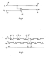
- FIG. 1 a sensor arrangement according to the prior art is shown in supervision.
- An aperture wheel 10 has markings 12, the number corresponding to the number of cylinders of the internal combustion engine.
- a sensor or sensor 14 detects the passage of the marker 12 during the rotation of the aperture wheel 10 and emits a signal during the duration of the passage.
- FIG. 2 shows the side view of such a construction, the sensor 14 being shown as a Hall element, which detects cutouts 12 in the aperture wheel 10.
- an aperture wheel 10 is also provided which bears markings 12, each marking 12 covering an angular range ⁇ and generating a signal in passing 14 in the sensor 14, the duration of which is accordingly determined by the rotational speed of the aperture wheel 10 and the angle ⁇ .
- a marking 18 assigned to a predetermined reference cylinder differs from the other markings 12 in size. It covers an angular range that is larger by an angle ⁇ than the angle ⁇ .
- a second sensor 16 is provided, offset by an angle ⁇ to the sensor 14, which is identical in construction to the sensor 14.
- the markings are preferably provided as recesses in a with a metallic diaphragm wheel, while the sensors 14 and 16 are designed as Hall elements.
- Other pairings customary in the prior art such as openings and photocells, light sources and photocells, or phototransistors, magnets and read relays or the like can of course also be used.
- Each of the markings 12 and 18 generates a signal S1 in the sensor 14 and a signal S2 in the sensor 16.
- the signals S1 and S2 are determined in a subsequent evaluation circuit to generate the reference signal, which should only occur when the marker 18 passes by.
- FIG. 4 shows a first simple evaluation circuit in which the signal S1 from the sensor 14 is fed to an input 20 and the signal S2 from the sensor 16 is fed to an input 22.
- the signal 20 is tapped again at the output 24 and is used there as a speed signal, for example in order to be able to derive emergency running properties of the internal combustion engine. Since the signal S1 does not pass through any active components, a failure of the evaluation circuit does not affect the presence of the emergency operation signal.
- the evaluation circuit is essentially formed by an AND gate 28, which detects when both the signal S1 and the signal S2 are present, and in this phase a reference signal is generated at the output 26.
- the signals derived in FIG. 5 are based on an aperture wheel 10, the recess ⁇ of which corresponds to an angle of rotation of 30 ° of the camshaft and the angle ⁇ of which corresponds to an angle of 45 ° camshaft.
- the signal S1 shown in FIG. 5a is fed to one input of the NAND gate 28, the signal S2 shown in FIG. 5b is identical to the signal S1 in FIG. 5a with regard to its signal sequence, but out of phase by the angle ⁇ .
- the tuning of the angles ⁇ , ⁇ and ⁇ is such that only when the wider marking 18 passes the sensors 14 and 16 both sensors 14 and 16 simultaneously pick up a signal, as a result of which a signal occurs at the output of the NAND gate 28, which after renewed negation, can be tapped at the output as reference signal 26 and is correspondingly shown in FIG. 5c.
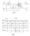
- FIG. 6 shows a further embodiment of the evaluation circuit which is used to convert the reference double pulse shown in FIG. 5c into a unique reference pulse.
- the signal S1 of the encoder 14 is applied to the input 20 of the circuit, the signal S2 of the encoder 18 to the input 22. As in the circuit according to FIG. 4, the signal at the input 20 is simultaneously present at the output 24 as a speed signal.
- the signal from input 20 is set to the trigger input of a D flip-flop 30, which occurs every time the rear Edge of a marker 12 or 18 runs past the sensor 14, is triggered and thus the Q output of the D flip-flop only switches to the "high” state if, at the time of the positive trigger edge, the data input previously Had “low” status.
- a pulse sequence thus arises at the output of the flip-flop, which changes to the "high” state only once per revolution of the diaphragm wheel encoder 10, specifically at the end of the slot C when its rear flank passes the sensor 14.
- the speed signal tapped at the output 24 has a different width depending on the width of the markings 12 and 18, and thus an uneven duty cycle, since it is the simple connection of the signal S1 from the encoder 14.
- Fig. 8 shows another evaluation circuit in which the speed signal has the same duty cycle if the angle ⁇ between the two sensors 14 and 16 is chosen equal to the angular width ⁇ of the markings A, B, D.
- an input 20 and an input 22 are provided, to which the signals S1 and S2 of the sensors 14 and 16 are fed, the reference signal is tapped at the output of the circuit 26, the speed signal at the output 24.
- a D flip-flop 36 is provided in the circuit, at the reset input of which signal S1 from input 20 is applied.
- the D input of the flip-flop 36 receives the negated signal S1, and the clock input of the flip-flop 36 is supplied with the output signal of a NAND gate 34, at whose one input the negated signal S1 tapped at the gate 32 is present and on whose other input the signal S2 is present.
- the output of this NAND gate 34 simultaneously provides the desired speed signal n at the output 24 of the evaluation circuit.
- FIG. 9a the signal S1 from sensor 14 is shown
- FIG. 9b the signal S2 from sensor 16 is shown poses.
- 9c shows the signal present at the data input of the flip-flop 36, which is the negated signal from S1, that is is. Since the signal from FIG. 9b and the signal from FIG. 9c are respectively fed to the NAND gate 34 at the inputs, the signal in FIG. 9d is the signal present at the output of the NAND gate 34, which can be used as a speed signal , the clock ratio of the signal according to FIG. 9d being constant.
- the inverted signal S1 is "low", so that the flip-flop 36 is not set by this signal when the clock input is activated.
Abstract
Es wird eine Geberanordung (10) zum Einsatz in einer Brennkraftmaschine beschrieben, mit Hilfe derer eine zylinderselektive Ansteuerung durch die Motorelektronik möglich ist. Dazu sind auf einem Signalgeber, üblicherweise der Verteilerblende, einem Zylinder ein längeres Signal zugeordnet als den anderen Zylindern. Durch zwei winkelig zueinander angeordneten Sensoren (14, 16) wird das längere Signal als Referenzsignal ausgewertet. 
Description
Die Erfindung betrifft eine Geberanordnung zur Drehzahlerkennung des Kurbelwellenwinkels an der Brennkraftmaschine gemäß Oberbegriff des Anspruchs 1.The invention relates to an encoder arrangement for speed detection of the crankshaft angle on the internal combustion engine according to the preamble of claim 1.
Derartige Geberanordnungen werden heute in Brennkraftmaschinen serienmäßig verwendet, um für Zündzeitpunktsteuerungen oder -regelungen ein Zylindersignal zu liefern, das in fester Beziehung zu einer vorgegebenen Stellung, beispielsweise dem oberen Totpunkt, eines Zylinders steht.Such sensor arrangements are used today as standard in internal combustion engines in order to deliver a cylinder signal for ignition timing controls which is in a fixed relationship to a predetermined position, for example the top dead center of a cylinder.
Üblicherweise werden derartige Signale durch eine am Verteiler vorgesehene Blende erzeugt, die Ausschnitte trägt, die mit Hilfe eines Hall-Elementes erfaßt werden. Selbstverständlich sind auch andere Geberelemente wie Fotozellen, Reedrelais oder ähnliches möglich.Such signals are usually generated by an aperture provided on the distributor, which carries cutouts which are detected with the aid of a Hall element. Of course, other encoder elements such as photocells, reed relays or the like are also possible.
Derartige Geberanordnungen legen zwar die Stellung beispielsweise des oberen Totpunktes eines Zylinders fest, sie sind jedoch nicht in der Lage, zylinderselektive Signale zu erzeugen. Dazu ist es notwendig, der nachfolgenden Logik in irgendeiner Form mitzuteilen, wann der Arbeitstakt einer 720° Kurbelwellenwinkel dauernden Arbeitsabfolge eines Motors beginnt.Such encoder arrangements determine the position, for example, of the top dead center of a cylinder, but they are not able to generate cylinder-selective signals. To do this, it is necessary to inform the following logic in some form when the work cycle of a 720 ° crankshaft angle work sequence of an engine begins.
Aufgabe der Erfindung ist es, eine Geberanordnung zu schaffen, mit der ein Referenzzylinder der Brennkraftmaschine gezielt einer bestimmten Kurbelwellenwinkelstellung zugeordnet werden kann.The object of the invention is to provide a sensor arrangement with which a reference cylinder of the internal combustion engine can be specifically assigned to a specific crankshaft angle position.
Die Aufgabe wird gelöst durch den Hauptanspruch.The task is solved by the main claim.
Erfindungsgemäß ist vorgesehen, daß dem einen Sensor zur Erfassung der Markierung noch ein zweiter Sensor im vorgegebenen Winkelabstand zum ersten Sensor zugeordnet wird, und das Signal des zweiten Sensors gibt im Vergleich mit dem Signal des ersten Sensors eine Auskunft darüber, ob die beiden Sensoren eine relativ kurze oder relativ längere Markierung auf dem Signalgeber erfaßt haben. Somit kann eine relativ längere Markierung, die dem Referenzsignal zugeordnet wird, von den kürzeren Zylindermarkierungen diskriminiert werden.According to the invention, it is provided that a sensor for detecting the marking is assigned a second sensor at a predetermined angular distance from the first sensor, and the signal from the second sensor, in comparison with the signal from the first sensor, provides information as to whether the two sensors are relative have detected short or relatively long marks on the signal transmitter. A relatively longer mark, which is assigned to the reference signal, can thus be discriminated against by the shorter cylinder markings.
Bevorzugte Ausführungsformen sind in den Unteransprüchen beschrieben. Die einzelnen Vorteile dieser jeweiligen Ausführungsformen wird in Verbindung mit den zugehörigen Zeichnungen detailliert dargestellt.Preferred embodiments are described in the subclaims. The individual advantages of these respective embodiments are shown in detail in conjunction with the associated drawings.
Im folgenden wird die Erfindung anhand der Zeichnungen näher dargestellt. Es zeigen:
- Fig. 1 die Darstellung eines Gebers gemäß Stand der Technik in Aufsicht;
- Fig. 2 die Vorrichtung nach Fig. 1 in Seitenansicht;
- Fig. 3 die erfindungsgemäße Geberanordnung in Aufsicht;
- Fig. 4 eine erste Auswerteschaltung zur Signalverarbeitung;
- Fig. 5 eine Darstellung der in der Schaltung nach Fig. 4 auftretenden Signale;
- Fig. 6 eine zweite Ausführungsform der Auswerteschaltung;
- Fig. 7 eine Darstellung der in der Schaltung nach Fig. 6 auftretenden Signale;
- Fig. 8 eine dritte Ausführungsform der Auswerteschaltung; und
- Fig. 9 die in der Auswerteschaltung nach Fig. 8 auftretenden Signale.
- Figure 1 shows the representation of a sensor according to the prior art in supervision.
- Fig. 2 shows the device of Figure 1 in side view.
- 3 shows the sensor arrangement according to the invention in supervision;
- 4 shows a first evaluation circuit for signal processing;
- Fig. 5 is an illustration of the signals appearing in the circuit of Fig. 4;
- 6 shows a second embodiment of the evaluation circuit;
- Fig. 7 is an illustration of the signals appearing in the circuit of Fig. 6;
- 8 shows a third embodiment of the evaluation circuit; and
- 9 shows the signals occurring in the evaluation circuit according to FIG. 8.
In Fig. 1 ist eine Geberanordnung gemäß Stand der Technik in Aufsicht gezeigt. Ein Blendenrad 10 besitzt Markierungen 12, wobei die Anzahl der Anzahl der Zylinder der Brennkraftmaschine entspricht. Ein Sensor oder Geber 14 erfaßt während der Umdrehung des Blendenrades 10 das Vorbeilaufen der Markierung 12 und gibt während der Dauer des Vorbeilaufes ein Signal ab.In Fig. 1, a sensor arrangement according to the prior art is shown in supervision. An
In Fig. 2 ist die Seitenansicht eines derartigen Aufbaus gezeigt, dabei ist der Sensor 14 als Hall-Element dargestellt, das Aussparungen 12 im Blendenrad 10 erfaßt.2 shows the side view of such a construction, the
Bei dieser Anordnung ist es nicht möglich, die Zuordnung zwischen der Markierung 12 und dem zugehörigen Zylinder der Brennkraftmaschine eindeutig festzustellen.With this arrangement, it is not possible to unambiguously determine the association between the marking 12 and the associated cylinder of the internal combustion engine.
Zur Erfassung eines vorgegebenen Referenzzylinders ist der in Fig. 3 dargestellte Aufbau vorgesehen, bei dem eine der Markierungen sich von den anderen Markierungen unterscheidet, um dadurch ein Referenzsignal zu erzeugen.3, in which one of the markings differs from the other markings in order to thereby generate a reference signal.
Erfindungsgemäß ist ebenfalls ein Blendenrad 10 vorgesehen, das Markierungen 12 trägt, wobei jede Markierung 12 einen Winkelbereich γ überdeckt und im Vorbeilauf in dem Sensor 14 ein Signal erzeugt, dessen Dauer sich dementsprechend aus der Umdrehungsgeschwindigkeit des Blendenrades 10 und der Winkel γ bestimmt.According to the invention, an
Eine einem vorbestimmten Referrenzzylinder zugeordnete Markierung 18 unterscheidet sich von den übrigen Markierungen 12 durch die Größe. Sie überdeckt einen Winkelbereich, der um einen Winkel α größer ist als der Winkel γ.A marking 18 assigned to a predetermined reference cylinder differs from the
Weiterhin ist, um einen Winkel β zum Sensor 14 versetzt, ein zweiter Sensor 16 vorgesehen, der im Aufbau identisch dem Sensor 14 ist.Furthermore, a
Wie in den Fig. 1 und 2 dargestellt, sind vorzugsweise die Markierungen als Aussparungen in einem mit metallischen Blendenrad vorgesehen, während die Sensoren 14 und 16 als Hall-Elemente ausgeführt sind. Andere im Stand der Technik übliche Paarungen, wie Durchbrüche und Fotozellen, Lichtquellen und Fotozellen, bzw. Fototransistoren, Magnete und Readrelais oder ähnliches können selbstverständlich ebenfalls Verwendung finden.As shown in FIGS. 1 and 2, the markings are preferably provided as recesses in a with a metallic diaphragm wheel, while the
Jede der Markierungen 12 bzw. 18 erzeugt in dem Sensor 14 ein Signal S1, und in dem Sensor 16 ein Signal S2. Die Signale S1 bzw. S2 werden in einer nachfolgenden Auswerteschaltung dazu bestimmt, das Referenzsignal, das immer nur bei dem Vorbeilauf der Markierung 18 auftreten soll, zu erzeugen.Each of the
Die zugehörigen Auswerteschaltungen sowie der Signalverlauf in den Auswerteschaltungen werden unter Bezugnahme auf die folgenden Figuren beschrieben. Aus den Signalabläufen ergeben sich gleichzeitig die Anforderungen, die an die Größenordnungen der Winkel α, β und γ zu stellen sind.The associated evaluation circuits and the signal curve in the evaluation circuits are described with reference to the following figures. The signal sequences also result in the requirements that have to be placed on the magnitudes of the angles α, β and γ.
Fig. 4 zeigt eine erste einfache Auswertschaltung, in der das Signal S1 vom Sensor 14 einem Eingang 20 und das Signal S2 vom Sensor 16 einem Eingang 22 zugeführt wird. Das Signal 20 wird gleichzeitig am Ausgang 24 wieder abgegriffen und dient dort als Drehzahlsignal, beispielsweise, um Notlaufeigenschaften der Brennkraftmaschine ableiten zu können. Da das Signal S1 keine aktiven Bauelemente durchläuft, beeinträchtig einen Ausfall der Auswerteschaltung das Vorhandensein des Notlaufsignales nicht.4 shows a first simple evaluation circuit in which the signal S1 from the
Die Auswertschaltung wird im wesentlichen gebildet durch ein Und-Gatter 28, das erfaßt, wann sowohl das Signal S1 als auch das Signal S2 anliegen, und in dieser Phase wird ein Referenzsignal am Ausgang 26 erzeugt.The evaluation circuit is essentially formed by an
Zum Verständnis der Schaltungen ist notwendig, darauf hinzuweisen, daß die Schaltungen in negativer Logik ausgelegt sind, so daß das Anliegen eines Signales durch den Zustand "low" repräsentiert wird.To understand the circuits, it is necessary to point out that the circuits are designed in negative logic, so that the presence of a signal is represented by the "low" state.
Die in Fig. 5 abgeleiteten Signale beruhen auf einem Blendenrad 10, dessen Aussparung α einem Drehwinkel von 30° der Nockenwelle entspricht und dessen Winkel β einen Winkel von 45° Nockenwelle entspricht.The signals derived in FIG. 5 are based on an
Das in Fig. 5a dargestellte Signal S1 wird dem einen Eingang des NAND-Gatters 28 zugeführt, das in Fig. 5b dargestellte Signal S2 ist identisch mit dem Signal S1 in Fig. 5a im Hinblick auf seine Signalabfolge, jedoch phasenversetzt um den Winkel β. Die Abstimmungen der Winkel α, β und γ ist so, daß nur bei Vorbeilauf der breiteren Markierung 18 an den Sensoren 14 und 16 beide Sensoren 14 und 16 gleichzeitig ein Signal abgreifen, wodurch am Ausgang des NAND-Gatters 28 ein Signal auftritt, was, nach erneuter Negierung, als Referenzsignal 26 am Ausgang abgreifbar ist und in Fig. 5c entsprechend dargestellt ist.The signal S1 shown in FIG. 5a is fed to one input of the
Fig. 6 zeigt eine weitere Ausführungsmöglichkeit der Auswerteschaltung, die verwendet wird, um den in Fig. 5c dargestellten Referenzdoppelimpuls in einen eindeutigen Referenzimpuls umzusetzen.FIG. 6 shows a further embodiment of the evaluation circuit which is used to convert the reference double pulse shown in FIG. 5c into a unique reference pulse.
Das Signal S1 des Gebers 14 wird an den Eingang 20 der Schaltung gelegt, das Signal S2 des Gebers 18 an den Eingang 22. Wie bei der Schaltung nach Fig. 4 liegt das Signal am Eingang 20 gleichzeitig am Ausgang 24 als Drehzahlsignal an.The signal S1 of the
Gleichzeitig wird das Signal vom Eingang 20 auf den Trigger-Eingang eines D-Flip-Flops 30 gesetzt, das jedesmal, wenn die rückwärtige Kante einer Markierung 12 bzw. 18 an dem Sensor 14 vorbeiläuft, getriggert wird und damit der Q-Ausgang des D-Flip-Flops nur dann in den Zustand "high" schaltet, wenn zu der Zeit der positiven Trigger-Flanke der Dateneingang vorher den Zustand "low" hatte. Somit entsteht am Ausgang des Flip-Flops eine Impulsfolge, die nur einmal pro Umdrehung des Blendenradgebers 10 in den Zustand "high" übergeht, und zwar genau am Ende des Schlitzes C, wenn dessen rückwärtige Flanke den Sensor 14 passiert.At the same time, the signal from
Das am Ausgang 24 abgegriffene Drehzahlsignal hat, da es die einfache Durchschaltung des Signales S1 vom Geber 14 ist, unterschiedliche, von der Breite der Markierungen 12 bzw. 18 abhängige Breite und somit ein ungleiches Tastverhältnis.The speed signal tapped at the
Fig. 8 zeigt eine andere Auswerteschaltung bei der das Drehzahlsignal gleiches Tastverhältnis, wenn der Winkel β zwischen den beiden Sensoren 14 bzw. 16 gleich der Winkelbreite γ der Markierungen A, B, D gewählt wird, besitzt.Fig. 8 shows another evaluation circuit in which the speed signal has the same duty cycle if the angle β between the two
Wiederum ist ein Eingang 20 und eine Eingang 22 vorgesehen, dem die Signale S1 und S2 der Sensoren 14 und 16 zugeführt werden, das Referenzsignal wird am Ausgang der Schaltung 26 abgegriffen, das Drehzahlsignal am Ausgang 24.Again, an
Es ist in der Schaltung ein D-Flip-Flop 36 vorgesehen, an dessen Reset-Eingang das Signal S1 vom Eingang 20 gelegt wird. Der D-Eingang des Flip-Flops 36 erhält das negierte Signal S1, und dem Clock-Eingang des Flip-Flops 36 wird das Ausgangssignal eines NAND-Gatters 34 zugeführt, an dessen einen Eingang das am Gatter 32 abgegriffene negierte Signal S1 anliegt und an dessen anderen Eingang das Signal S2 anliegt. Der Ausgang dieses NAND-Gatters 34 liefert gleichzeitig am Ausgang 24 der Auswerteschaltung das gewünschte Drehzahlsignal n.A D flip-
Die Funktion der Schaltung ist folgende: In Fig. 9a ist das Signal S1 vom Sensor 14, in Fig. 9b ist das Signal S2 vom Sensor 16 darge stellt. Fig. 9c zeigt das am Dateneingang des Flip-Flops 36 anstehende Signal, das das negierte Signal von S1, also![]()
![]()
Zu den dargestellten Zeitpunkten t1, t2, t5 und t6 ist das invertierte Signal S1 "low", so daß das Flip-Flop 36 durch dieses Signal bei der Ansteuerung des Clock-Einganges nicht gesetzt wird.At the represented times t1, t2, t5 and t6, the inverted signal S1 is "low", so that the flip-
Zum Zeitpunkt t3 ist durch die Schlitzverbreiterung α das Signal![]()
![]()
Claims (10)
einem mit halber Drehzahl der Kurbelwelle mitlaufenden Signalgeber,
dem Signalgeber zugeordneten, in ihrer Anzahl auf die Zylinderanzahl abgestimmten Markierungen, durch die während eines bestimmten Kurbelwellenwinkelbereichs ein Signal erzeugbar ist,
einem ersten Sensor, der die Markierungen abfragt,
einer Auswertschaltung, die während des Vorbeilaufs der Markierungen an dem Sensor ein Signal erzeugt,
dadurch gekennzeichnet, daß eine (18) der Markierungen einen relativ größeren Kurbelwellenwinkelbereich (α + γ) abdeckt als die restlichen Markierungen (12), und daß ein zweiter Sensor (16) vorgesehen ist, der in einem definierten Winkelabstand (β) hinsichtlich des Drehwinkels des Signalgebers (10) zu dem ersten Sensor (14) angeordnet ist, wobei das Signal des zweiten Sensors (16) ebenfalls der Auswertschaltung zugeführt wird.1. Encoder arrangement for detecting the angle of rotation of the crankshaft of an internal combustion engine, with
a signal transmitter running at half the crankshaft speed,
the number of markings assigned to the signal transmitter and matched to the number of cylinders, by means of which a signal can be generated during a specific crankshaft angle range,
a first sensor that queries the markings,
an evaluation circuit that generates a signal while the markings pass the sensor,
characterized in that one (18) of the markings covers a relatively larger crankshaft angle range (α + γ) than the remaining markings (12), and that a second sensor (16) is provided which is at a defined angular distance (β) with respect to the angle of rotation of the signal generator (10) to the first sensor (14), the signal of the second sensor (16) also being fed to the evaluation circuit.
Applications Claiming Priority (2)
| Application Number | Priority Date | Filing Date | Title |
|---|---|---|---|
| DE19863602292 DE3602292A1 (en) | 1986-01-25 | 1986-01-25 | TRANSMITTER ARRANGEMENT |
| DE3602292 | 1986-01-25 |
Publications (3)
| Publication Number | Publication Date |
|---|---|
| EP0230560A2 true EP0230560A2 (en) | 1987-08-05 |
| EP0230560A3 EP0230560A3 (en) | 1987-11-11 |
| EP0230560B1 EP0230560B1 (en) | 1991-01-16 |
Family
ID=6292660
Family Applications (1)
| Application Number | Title | Priority Date | Filing Date |
|---|---|---|---|
| EP86116612A Expired - Lifetime EP0230560B1 (en) | 1986-01-25 | 1986-11-28 | Angle sensor arrangement |
Country Status (5)
| Country | Link |
|---|---|
| US (1) | US4783627A (en) |
| EP (1) | EP0230560B1 (en) |
| JP (1) | JPS62190408A (en) |
| DE (2) | DE3602292A1 (en) |
| ES (1) | ES2019580B3 (en) |
Cited By (3)
| Publication number | Priority date | Publication date | Assignee | Title |
|---|---|---|---|---|
| FR2637652A1 (en) * | 1988-10-11 | 1990-04-13 | Bendix Electronics Sa | Device for marking an operating cycle of an internal combustion engine |
| GB2234345A (en) * | 1989-06-06 | 1991-01-30 | Asahi Optical Co Ltd | Position sensing device |
| EP0879956A1 (en) * | 1988-05-16 | 1998-11-25 | Motorola, Inc. | Electronic position sensor assembly and control system |
Families Citing this family (21)
| Publication number | Priority date | Publication date | Assignee | Title |
|---|---|---|---|---|
| DE3634587A1 (en) * | 1986-10-10 | 1988-04-14 | Bosch Gmbh Robert | IGNITION SYSTEM FOR COMBUSTION ENGINES |
| JPS63253220A (en) * | 1987-04-10 | 1988-10-20 | Hitachi Ltd | Measuring instrument for angle of rotation |
| US4972332A (en) * | 1987-07-28 | 1990-11-20 | Caterpillar Inc. | Apparatus for determining the speed, angular position and direction of rotation of a rotatable shaft |
| JPH0174376U (en) * | 1987-11-09 | 1989-05-19 | ||
| JPH0715279B2 (en) * | 1988-10-14 | 1995-02-22 | 三菱電機株式会社 | Ignition timing control device |
| BR8807887A (en) * | 1988-12-09 | 1990-11-27 | Caterpillar Inc | DEVICE FOR DETERMINING SPEED, ANGLE POSITION AND ROTATION DIRECTION OF A ROTATING AXIS |
| FR2650632B1 (en) * | 1989-08-03 | 1994-04-29 | Renault Vehicules Ind | DETECTION METHOD AND DEVICE FOR ELECTRONIC INJECTION DRIVING OF A MULTICYLINDER ENGINE |
| WO1993009393A1 (en) * | 1991-11-06 | 1993-05-13 | Orbital Engine Company (Australia) Pty. Limited | Method and apparatus for determining position of a body in cyclic movement |
| US5341097A (en) * | 1992-09-29 | 1994-08-23 | Honeywell Inc. | Asymmetrical magnetic position detector |
| US5497083A (en) * | 1992-12-24 | 1996-03-05 | Kayaba Kogyo Kabushiki Kaisha | Rod axial position detector including a first scale having equidistant magnetic parts and a second scale having unequally distant parts and differing field strengths |
| DE19520683A1 (en) * | 1995-06-07 | 1996-12-12 | Teves Gmbh Alfred | Arrangement for detecting a movement |
| AT2385U1 (en) * | 1997-09-09 | 1998-09-25 | Amo Automatisierung Messtechni | ANGLE MEASURING SYSTEM |
| DE19959425A1 (en) * | 1999-12-09 | 2001-06-21 | Siemens Ag | Movement measuring apparatus with increased resolution especially for measuring rotation rate of a rotor |
| US6841962B2 (en) * | 2001-08-31 | 2005-01-11 | Package Machinery Co. Inc. | Reciprocating linear actuator |
| DE10160846A1 (en) * | 2001-12-12 | 2003-07-10 | Valeo Auto Electric Gmbh | Actuating device, in particular for actuating limited slip differentials of vehicles |
| DE102010001431A1 (en) | 2010-02-01 | 2011-08-04 | Osram Gesellschaft mit beschränkter Haftung, 81543 | Optical system |
| DE102015209866A1 (en) * | 2015-05-29 | 2016-12-01 | Zf Friedrichshafen Ag | Method for condition monitoring of at least one planetary gear of a planetary gear |
| DE102015209865B4 (en) * | 2015-05-29 | 2022-08-25 | Zf Friedrichshafen Ag | Process for acquiring sensor signals |
| DE102015209867A1 (en) * | 2015-05-29 | 2016-12-01 | Zf Friedrichshafen Ag | Method for condition monitoring of at least one planetary gear of a planetary gear |
| DE102015209868A1 (en) * | 2015-05-29 | 2016-12-01 | Zf Friedrichshafen Ag | Planetary gear with at least one sensor |
| FR3083860B1 (en) * | 2018-07-13 | 2021-01-15 | Continental Automotive France | TREATMENT PROCESS FOR CAMSHAFT SENSOR |
Citations (6)
| Publication number | Priority date | Publication date | Assignee | Title |
|---|---|---|---|---|
| US4181884A (en) * | 1977-07-20 | 1980-01-01 | Nippondenso Co., Ltd. | Rotational position detection device using a reference mark and two sensors spaced integer times apart |
| EP0010033A1 (en) * | 1978-09-29 | 1980-04-16 | Psa Etudes Et Recherches | Angular position sensor for an internal combustion engine fitted with an electronic ignition system |
| FR2444274A1 (en) * | 1978-12-14 | 1980-07-11 | Bosch Gmbh Robert | Engine shaft revolution rate and rotation angle measurement - using hall generator segmented control wheel with distinguishing projecting tooth |
| FR2445511A1 (en) * | 1978-12-28 | 1980-07-25 | Thomson Csf | Piston position sensor for IC engine - uses leakage inductance damping in free-running oscillator within rotor and with output fed to level comparator |
| EP0101332A1 (en) * | 1982-07-28 | 1984-02-22 | Automobiles Peugeot | Synchronisation device for an electronic ignition system |
| US4442822A (en) * | 1981-10-22 | 1984-04-17 | Kokusan Denki Co., Ltd. | Ignition position controlling apparatus for multicylinder internal combustion engine |
Family Cites Families (13)
| Publication number | Priority date | Publication date | Assignee | Title |
|---|---|---|---|---|
| GB1490987A (en) * | 1974-03-08 | 1977-11-09 | Westinghouse Brake & Signal | Vehicle movement control arrangements |
| US3944923A (en) * | 1974-05-22 | 1976-03-16 | Frank Kenneth Luteran | Device for sensing the direction of motion |
| US4089316A (en) * | 1976-04-05 | 1978-05-16 | Motorola, Inc. | Adjustable rotary position sensor for electronic spark timing control |
| FR2428151A1 (en) * | 1978-06-08 | 1980-01-04 | Peugeot | DEVICE FOR TRIGGERING, PARTICULARLY THE IGNITION OF AN INTERNAL COMBUSTION ENGINE |
| US4280165A (en) * | 1979-04-24 | 1981-07-21 | Pospelov Boris S | Device for measuring angular position of a gear in a digital ignition system of an internal combustion engine |
| JPS5924970Y2 (en) * | 1979-07-10 | 1984-07-23 | 株式会社デンソー | Rotational position detection device |
| JPS5619759U (en) * | 1979-07-25 | 1981-02-21 | ||
| US4313414A (en) * | 1980-01-14 | 1982-02-02 | Thomson-Csf | Shaft position sensor for an internal combustion engine equipped with an electronic ignition system |
| DE3017972C2 (en) * | 1980-05-10 | 1995-01-26 | Bosch Gmbh Robert | Control device for multiple ignition and / or fuel injection output stages for internal combustion engines |
| JPS5826339U (en) * | 1981-08-17 | 1983-02-19 | 株式会社コトブキ | Deck support structure for folding table |
| JPS5850257U (en) * | 1981-09-25 | 1983-04-05 | 日本ケ−ブル・システム株式会社 | Control cable drive device |
| DE3220896A1 (en) * | 1982-06-03 | 1983-12-08 | Robert Bosch Gmbh, 7000 Stuttgart | SENSOR |
| JPS59226232A (en) * | 1983-06-06 | 1984-12-19 | Nippon Denso Co Ltd | Apparatus for detecting rotational position of internal- combustion engine |
-
1986
- 1986-01-25 DE DE19863602292 patent/DE3602292A1/en active Granted
- 1986-11-28 ES ES86116612T patent/ES2019580B3/en not_active Expired - Lifetime
- 1986-11-28 DE DE8686116612T patent/DE3676990D1/en not_active Revoked
- 1986-11-28 EP EP86116612A patent/EP0230560B1/en not_active Expired - Lifetime
-
1987
- 1987-01-26 JP JP62017124A patent/JPS62190408A/en active Pending
- 1987-01-27 US US07/006,998 patent/US4783627A/en not_active Expired - Fee Related
Patent Citations (6)
| Publication number | Priority date | Publication date | Assignee | Title |
|---|---|---|---|---|
| US4181884A (en) * | 1977-07-20 | 1980-01-01 | Nippondenso Co., Ltd. | Rotational position detection device using a reference mark and two sensors spaced integer times apart |
| EP0010033A1 (en) * | 1978-09-29 | 1980-04-16 | Psa Etudes Et Recherches | Angular position sensor for an internal combustion engine fitted with an electronic ignition system |
| FR2444274A1 (en) * | 1978-12-14 | 1980-07-11 | Bosch Gmbh Robert | Engine shaft revolution rate and rotation angle measurement - using hall generator segmented control wheel with distinguishing projecting tooth |
| FR2445511A1 (en) * | 1978-12-28 | 1980-07-25 | Thomson Csf | Piston position sensor for IC engine - uses leakage inductance damping in free-running oscillator within rotor and with output fed to level comparator |
| US4442822A (en) * | 1981-10-22 | 1984-04-17 | Kokusan Denki Co., Ltd. | Ignition position controlling apparatus for multicylinder internal combustion engine |
| EP0101332A1 (en) * | 1982-07-28 | 1984-02-22 | Automobiles Peugeot | Synchronisation device for an electronic ignition system |
Cited By (4)
| Publication number | Priority date | Publication date | Assignee | Title |
|---|---|---|---|---|
| EP0879956A1 (en) * | 1988-05-16 | 1998-11-25 | Motorola, Inc. | Electronic position sensor assembly and control system |
| FR2637652A1 (en) * | 1988-10-11 | 1990-04-13 | Bendix Electronics Sa | Device for marking an operating cycle of an internal combustion engine |
| GB2234345A (en) * | 1989-06-06 | 1991-01-30 | Asahi Optical Co Ltd | Position sensing device |
| US5073790A (en) * | 1989-06-06 | 1991-12-17 | Asahi Kogaku Kogyo Kabushiki Kaisha | Position sensing device |
Also Published As
| Publication number | Publication date |
|---|---|
| JPS62190408A (en) | 1987-08-20 |
| DE3676990D1 (en) | 1991-02-21 |
| DE3602292C2 (en) | 1990-08-30 |
| EP0230560B1 (en) | 1991-01-16 |
| EP0230560A3 (en) | 1987-11-11 |
| ES2019580B3 (en) | 1991-07-01 |
| DE3602292A1 (en) | 1987-08-06 |
| US4783627A (en) | 1988-11-08 |
Similar Documents
| Publication | Publication Date | Title |
|---|---|---|
| EP0230560B1 (en) | Angle sensor arrangement | |
| DE2357061C2 (en) | Device for the delivery of uniform pulses at certain angular positions of a rotatable shaft and for the formation of at least one reference signal | |
| DE2326187C3 (en) | Device for the electronic adjustment of the ignition point and for the electronic triggering of the ignition process in ignition systems of internal combustion engines | |
| DE2951622C2 (en) | ||
| DE2933516A1 (en) | DEVICE FOR SPEED DETECTION AND ANGLE SEGMENT DETECTION OF A SHAFT, IN PARTICULAR THE CRANKSHAFT OF AN INTERNAL COMBUSTION ENGINE | |
| WO1980000597A1 (en) | Device for controlling,in combustion motor machines,operations which are repetitive and which depend on running parameters | |
| WO1987005971A1 (en) | Process for identifying the working cycle of a cylinder in an internal combustion engine | |
| DE2645350C3 (en) | Electronic ignition control device for internal combustion engines | |
| DE2644646C2 (en) | Device for detecting one or more missing pulses in an otherwise regular pulse train | |
| EP0745212B1 (en) | Process and device for determining the angular position of a rotating shaft | |
| DE3127220C2 (en) | Device for generating a speed-dependent signal sequence | |
| DE3034440A1 (en) | IGNITION SYSTEM FOR INTERNAL COMBUSTION ENGINES | |
| DE2614858C3 (en) | Electronic control device for the ignition of an internal combustion engine | |
| DE2703575A1 (en) | DEVICE FOR CONTROLLING THE IGNITION TIME OF A COMBUSTION ENGINE | |
| DE19513597C2 (en) | Method for cylinder recognition in an internal combustion engine | |
| DE2851336C2 (en) | ||
| DE2352941A1 (en) | METHOD AND EQUIPMENT FOR TRIGGERING A PULSE WITHIN AN ADJUSTMENT RANGE | |
| DE2847522A1 (en) | INDUCTIVE ENCODER AND EVALUATION HERE | |
| DE4041491C2 (en) | Sensor for generating electrical signals that represent the position of an object | |
| DE2931329C2 (en) | ||
| DE2648341C2 (en) | Electronic encoder device | |
| DE2058834C3 (en) | Device for determining the top dead center position of the piston of an internal combustion engine belonging to a motor vehicle | |
| DE2325479C3 (en) | Method and device for the speed-dependent setting of the ignition angle of a spark-ignition internal combustion engine | |
| EP1526354B1 (en) | Device and method for determining the angular position of a rotating element | |
| DE3017971C2 (en) |
Legal Events
| Date | Code | Title | Description |
|---|---|---|---|
| PUAI | Public reference made under article 153(3) epc to a published international application that has entered the european phase |
Free format text: ORIGINAL CODE: 0009012 |
|
| 17P | Request for examination filed |
Effective date: 19861128 |
|
| AK | Designated contracting states |
Kind code of ref document: A2 Designated state(s): DE ES FR GB IT SE |
|
| PUAL | Search report despatched |
Free format text: ORIGINAL CODE: 0009013 |
|
| RHK1 | Main classification (correction) |
Ipc: F02P 7/067 |
|
| AK | Designated contracting states |
Kind code of ref document: A3 Designated state(s): DE ES FR GB IT SE |
|
| 17Q | First examination report despatched |
Effective date: 19891102 |
|
| ITF | It: translation for a ep patent filed |
Owner name: DE DOMINICIS & MAYER S.R.L. |
|
| GRAA | (expected) grant |
Free format text: ORIGINAL CODE: 0009210 |
|
| AK | Designated contracting states |
Kind code of ref document: B1 Designated state(s): DE ES FR GB IT SE |
|
| GBT | Gb: translation of ep patent filed (gb section 77(6)(a)/1977) | ||
| REF | Corresponds to: |
Ref document number: 3676990 Country of ref document: DE Date of ref document: 19910221 |
|
| ET | Fr: translation filed | ||
| PLBI | Opposition filed |
Free format text: ORIGINAL CODE: 0009260 |
|
| 26 | Opposition filed |
Opponent name: ROBERT BOSCH GMBH Effective date: 19911015 |
|
| PGFP | Annual fee paid to national office [announced via postgrant information from national office to epo] |
Ref country code: GB Payment date: 19931021 Year of fee payment: 8 |
|
| PGFP | Annual fee paid to national office [announced via postgrant information from national office to epo] |
Ref country code: FR Payment date: 19931108 Year of fee payment: 8 |
|
| PGFP | Annual fee paid to national office [announced via postgrant information from national office to epo] |
Ref country code: SE Payment date: 19931116 Year of fee payment: 8 |
|
| PGFP | Annual fee paid to national office [announced via postgrant information from national office to epo] |
Ref country code: ES Payment date: 19931117 Year of fee payment: 8 |
|
| PGFP | Annual fee paid to national office [announced via postgrant information from national office to epo] |
Ref country code: DE Payment date: 19931210 Year of fee payment: 8 |
|
| RDAG | Patent revoked |
Free format text: ORIGINAL CODE: 0009271 |
|
| STAA | Information on the status of an ep patent application or granted ep patent |
Free format text: STATUS: PATENT REVOKED |
|
| 27W | Patent revoked |
Effective date: 19940101 |
|
| GBPR | Gb: patent revoked under art. 102 of the ep convention designating the uk as contracting state |
Free format text: 940101 |
|
| EUG | Se: european patent has lapsed |
Ref document number: 86116612.2 Effective date: 19940518 |