EP1526230A2 - Schlossanordnung - Google Patents
Schlossanordnung Download PDFInfo
- Publication number
- EP1526230A2 EP1526230A2 EP04256508A EP04256508A EP1526230A2 EP 1526230 A2 EP1526230 A2 EP 1526230A2 EP 04256508 A EP04256508 A EP 04256508A EP 04256508 A EP04256508 A EP 04256508A EP 1526230 A2 EP1526230 A2 EP 1526230A2
- Authority
- EP
- European Patent Office
- Prior art keywords
- stile
- lock
- cylinder
- protector
- backplate
- Prior art date
- Legal status (The legal status is an assumption and is not a legal conclusion. Google has not performed a legal analysis and makes no representation as to the accuracy of the status listed.)
- Withdrawn
Links
Images


Classifications
-
- E—FIXED CONSTRUCTIONS
- E05—LOCKS; KEYS; WINDOW OR DOOR FITTINGS; SAFES
- E05B—LOCKS; ACCESSORIES THEREFOR; HANDCUFFS
- E05B15/00—Other details of locks; Parts for engagement by bolts of fastening devices
- E05B15/02—Striking-plates; Keepers; Bolt staples; Escutcheons
-
- E—FIXED CONSTRUCTIONS
- E05—LOCKS; KEYS; WINDOW OR DOOR FITTINGS; SAFES
- E05B—LOCKS; ACCESSORIES THEREFOR; HANDCUFFS
- E05B9/00—Lock casings or latch-mechanism casings ; Fastening locks or fasteners or parts thereof to the wing
- E05B9/08—Fastening locks or fasteners or parts thereof, e.g. the casings of latch-bolt locks or cylinder locks to the wing
-
- E—FIXED CONSTRUCTIONS
- E05—LOCKS; KEYS; WINDOW OR DOOR FITTINGS; SAFES
- E05B—LOCKS; ACCESSORIES THEREFOR; HANDCUFFS
- E05B17/00—Accessories in connection with locks
- E05B17/20—Means independent of the locking mechanism for preventing unauthorised opening, e.g. for securing the bolt in the fastening position
- E05B17/2084—Means to prevent forced opening by attack, tampering or jimmying
Definitions
- This invention relates to a key operated lock assembly for a door or window, the assembly being of the kind in which a lock cylinder, containing the key operated lock barrel, protrudes from a face of the door or window stile fitted with a lock mechanism of the assembly, to be received within a backplate of handle furniture fitted to the face of the stile.
- the lock mechanism includes a dead bolt arrangement which is actuated by rotation of the lock barrel within the lock cylinder of the mechanism by means of an appropriate key, and a latch bolt which is operated by movement of the handle of the handle furniture fitted to the stile of the door.
- the lock mechanism is fitted within the door stile and the external door handle furniture includes a spring returned lever having a spindle operated by movement of the lever, the spindle passing through the lock mechanism to actuate the latch bolt, and cooperating with a corresponding handle of the furniture on the interior face of the stile.
- lock mechanism and handle furniture are within the ambit of the present invention; for example, the invention can be applied to an assembly which has only a single bolt which can be withdrawn against spring loading by movement of the handle of the furniture or rotation of the barrel by means of the key, and which can be locked in a protruding (operative) position by appropriate key actuation of the lock cylinder.
- the backplate may have a functional handle which is movable or a non-functional handle which is simply to allow the user to grip the door, or may be decorative and devoid of a handle, serving primarily to improve the door appearance by enclosing the protruding lock cylinder.
- the portion of the lock cylinder which protrudes from the external face of the stile is covered by the backplate of the handle furniture on the exterior face of the stile, the backplate having an aperture through which a key can be introduced, but not providing access to any portion of the lock cylinder for a grasping tool to apply wrenching force to the lock cylinder.
- the security afforded by the backplate is determined by the strength of the fixing of the backplate to the door stile. It is a first object of the present invention to provide a lock mechanism of enhanced security.
- a lock assembly including a lock mechanism to be received within a recess in a door or window stile, the lock mechanism having a lock cylinder which protrudes in use from an exterior face of the stile into a housing defined at the exterior face of the stile by the backplate of associated door/window furniture secured to the stile, and, a cylinder protector arranged to be received within said housing, and at the same time to receive within it the protruding portion of the lock cylinder, said cylinder protector being arranged to cooperate with the stile and said backplate to enhance the resistance of the fixing of the backplate against unauthorised removal of the backplate from the stile.
- said protector cooperates with a fixing element of said backplate.
- Prefèrably said cylinder protector co-acts with both the stile and a screw fixing boss of the backplate into which a fixing screw extends to secure the backplate to the stile.
- the cylinder protector includes an extension which is received within the body of the stile.
- the cylinder protector is secured to the stile other than by the backplate.
- the cylinder protector is secured to the stile by means of a through-fixing which extends through a load spreader plate engaging the inner face of the stile, through the stile, and co-acts with the cylinder protector at the exterior face of the stile.
- the through-fixing extends through the casing of the lock mechanism within the stile.
- the lock cylinder terminates adjacent the outer face of the cylinder protector so that there is insufficient protruding lock cylinder to permit the lock cylinder to be grasped, and more desirably the exterior surface shaping of the cylinder protector is curved and/or tapered in order to resist the cylinder protector being grasped.
- a lock assembly including a lock mechanism to be received within a recess in a door or window stile, the lock mechanism having a lock cylinder which protrudes in use from an exterior face of the stile, and, a cylinder protector secured to said stile and receiving within it the protruding portion of the lock cylinder, said lock cylinder terminating adjacent the outer face of the cylinder protector so that there is insufficient protruding lock cylinder to permit the lock cylinder to be grasped, and the exterior surface shaping of the cylinder protector being curved and/or tapered in order to resist the cylinder protector being grasped.
- a lock protector for use in lock assemblies as defined above.
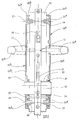
- the door stile 11 is formed from UPVC but it is to be understood that the invention can be applied to doors having wooden stiles, and the invention can also be applied to windows.
- the edge of the stile 11 which is presented to the door jamb when the door is in its closed position, is formed, in conventional manner, with a recess which extends into the plane of the drawing in Figure 2.
- the recess is shaped to receive the casing 13 and front plate 14 of a lock mechanism 12.
- the front plate 14 is recessed into the edge surface of the stile so that it is flush therewith. Fixing screws (not shown) extend through corresponding holes 15 in upper and lower extensions of the front plate 14 and serve to secure the front plate and lock casing in position in the stile.
- the internal construction of the lock mechanism in the casing 13 is not of relevance to the present invention, but in the example illustrated in Figures 1 and 2 there is a spring loaded latch bolt 16 which can be retracted against spring force by rotation of a drive spindle 17 passing transversely through the lock casing and cooperating with movable handles 19 a , 19 b of external and internal door furniture 18 a , 18 b secured to the corresponding faces of the stile 11.
- the lock mechanism includes a dead-bolt in the form of a hook-bolt 21 which can be caused to protrude from the lock front plate 14 and into a corresponding keep in the door jamb by movement of the handles 19 a , 19 b to drive the spindle 17 out of its normal range of latch bolt operation.
- the lock mechanism includes a key operated lock cylinder 22 containing a rotatable key receiving barrel 23 which can be actuated to lock the bolt 21 in its thrown condition, locking the bolt 21 in engagement with the corresponding keep in the door jamb.
- the key operation of the cylinder 22 can also be used to lock the whole of the internal mechanism of the lock assembly to prevent movement of the spindle 17 and the latch bolt 16.
- the lock assembly may include only a single operating bolt and in some applications the bolt can be actuated as well as locked by rotation of the barrel 23 by means of the key.
- the internal nature of the lock mechanism is not of significance to the invention.
- the external door furniture 18a of the lock assembly is substantially a mirror image of the internal door furniture 18b, and each comprises a cast, or stamped aluminium or aluminium alloy backing plate 23 a , 23 b rotatably supporting the respective handle 19 a , 19 b.
- Each of the backing plates 23 a , 23 b is formed with a peripheral upstanding wall 24 a , 24 b which serves to space the main, planar portion of the backing plate from the corresponding face of the stile 11 to accommodate, inter alia, the parts of the handles 19 which protrude through the backing plates to cooperate with the spindle 17.
- Upstanding from the internal face of each backing plate are upper and lower fixing bosses 25 a , 26 a ; 25 b , 26 b .
- the bosses 25 a , 26 a which are integral with the front or exterior backplate 23 a contain internally screw threaded blind bores which do not penetrate the front face of the backing plate 23 a .
- the bosses 25 b , 26 b of the interior backing plates 23 b which are aligned in use with the bosses 25 a , 26 a , have through bores with counter sunk recesses in the outer face of the backing plate 23 b , and elongate countersink head fixing screws 27, 28 extend through the bosses 25 b , 26 b respectively, passing through the stile 11 and above and below the lock casing 13 respectively, and are received in screw threaded engagement in the blind bores of the bosses 25 a , 26 a .
- the lock cylinder 22 extends through the lock casing 13 and protrudes from the opposite faces thereof.
- the protrusion of the lock cylinder 22 is such that both ends of the lock cylinder 22 protrude through the material of the stile 11, and through the gap between the stile 11 and the backing plates 23 a , 23 b , the backing plates being formed with "key-hole” shaped apertures to receive the end regions of the lock cylinder 22.
- the lock cylinder 22 is apertured to allow cooperation between parts of the mechanism within the casing 13 and the barrel 23 by means of an appropriate key.
- the lock assembly described so far is generally conventional. It is known that attempts have been made to operate the lock assembly without an appropriate key by destroying the lock cylinder 22 thereby to gain access to the interior of the casing 13. Such attempts are frustrated in the assembly described above as the lock cylinder 22 protrudes through the backplates 23 a , 23 b by an amount insufficient to allow the cylinder 22 to be grasped by a tool such as a Mole® grip and thus the door furniture frustrates the application of wrenching forces to the lock cylinder 22 to break the cylinder. However, it is known that attempts have been made to rip the door furniture from the door stile to gain access to the protruding parts of the lock cylinder 22.
- the fixing of the door furniture to the door stile by means of the fixing screws 27, 28 is robust, but can be defeated if sufficient leverage is applied to the door furniture to lift the door furniture away from the stile 11.
- sufficient leverage is applied to the exterior door furniture, and if sufficient leverage can be applied then the anchorage of the screws 27, 28 in the bosses 25 a , 26 a is known to fail, particularly if when the leverage is applied such that the anchorage of the screws 27, 28 in the bosses is subjected to axial and lateral forces, as can occur when the handle 19 a is used as the means of leverage.
- a cylinder protector 29 in the form of a cast or machined metal component which is received between the backplate 23 a and the stile 11.
- the cylinder protector 29 includes a planar body 31 which seats against the exterior face of the stile 11, and which is of sufficient thickness to fill the space between the stile 11 and the inner face of the backplate 23 a so that in its secured position the backplate 23 a seats against the outer face of the body 31 of the protector 29.
- the body 31 is formed with a generally frusto-conical aperture 32, having its wider end presented to the backplate 23 a , the aperture 32 receiving the boss 26 a .
- a rigid shroud 33 which protrudes from the rear face of the body 31 into a correspondingly shaped recess in the outer part of the stile 11.
- the shroud 31 is formed with a passage 34 which receives the outwardly protruding part of the lock cylinder 22 as a close fit.
- the passage 34 of the shroud 33 is continued forwardly to form a key-hole shaped aperture in the body 31 through which the cylinder 22 extends.
- the passage 34 is open along the lower edge of the shroud 33 so that the shroud 33 does not completely encase the lock cylinder 22.
- the omission of a portion of shroud lying beneath the lower edge of the lock cylinder 22 is purely for convenience of providing a fixing point for the cylinder protector 29.
- the shroud 33 extends completely around the lock cylinder 22.
- the body 31 is formed, between the shroud 33 and the aperture 32, with an internally screw threaded bore 35 which receives a fixing screw 36 extending through the stile 11 and the lock casing 13 (it being recognised that in an application using a smaller lock casing 13 the screw 36 will pass through the stile below the lock casing).
- a load spreading plate 37 is provided at the inner face of the stile and the screw 36 extends through an aperture in the plate 37 so that the screw 36 clamps the plate 37 against the inner face of the stile, pulling the protector 29 against the outer face of the stile.
- the plate 37 spreads the load of the head of the screw 36 across a greater area of the stile and so enhances the security of the fixing of the protector 29 to the stile. Moreover, desirably the plate 37 has a key hole shaped aperture 38 for receiving the internally projecting portion of the cylinder 22 and a frusto-conical aperture 39 for receiving the boss 26 b of the backplate 23 b . If desired the plate 37 could be of similar thickness to the body 31 of the protector 29.
- the protector 29 seats against the stile 11 and the shroud 33 is a close fit within an aperture in the stile, and is a close fit over the cylinder 22. Moreover, the edge surface of the body 31 of the protector 29 is chamfered or rounded so as to frustrate any attempt to grip the body 31 by means of a wrenching tool such as a Mole® grip or like tool.
- the protector 29 is securely fixed to the stile by fixing means 36 separate to the fixing of the backplates 23 a , 23 b . Moreover, the protector 29 supports the backplate 23 a both by filling the gap between the backplate 23 a and the stile 11, and by receiving and supporting the boss 26 a .
- the handle 19 a as a lever, then lateral loading on the screw fixing of the screw 28 in the boss 26 a is minimised by the support provided by the protector 29. Should an intruder ultimately be successful in wrenching the external door furniture from the door then the protector 29 will remain in place since its securing to the door is separate from the securing of the backplates.
- the stile is formed with a vertical elongate slot below the cylinder 22, which encompasses the bores through which the screws 36 and 28 extend.
- the protector is extended rearwardly around the threaded bore 35 to define a tapering boss 35 a receiving the screw shank and itself being received in the stile.
- the boss 35 a provides greater coaction with stile and greater thread length receiving the screw 36.
- the plate 37 has a similar integral boss 37 a around the hole which receives the screw 36 making the plate 37 more robust, around the screw head, and the boss 37 a is similarly received in the slot cut in the stile.
Landscapes
- Engineering & Computer Science (AREA)
- Mechanical Engineering (AREA)
- Securing Of Glass Panes Or The Like (AREA)
- Hinges (AREA)
Applications Claiming Priority (2)
| Application Number | Priority Date | Filing Date | Title |
|---|---|---|---|
| GB0324813A GB0324813D0 (en) | 2003-10-24 | 2003-10-24 | Lock assembly |
| GB0324813 | 2003-10-24 |
Publications (2)
| Publication Number | Publication Date |
|---|---|
| EP1526230A2 true EP1526230A2 (de) | 2005-04-27 |
| EP1526230A3 EP1526230A3 (de) | 2006-02-08 |
Family
ID=29595730
Family Applications (1)
| Application Number | Title | Priority Date | Filing Date |
|---|---|---|---|
| EP04256508A Withdrawn EP1526230A3 (de) | 2003-10-24 | 2004-10-22 | Schlossanordnung |
Country Status (2)
| Country | Link |
|---|---|
| EP (1) | EP1526230A3 (de) |
| GB (1) | GB0324813D0 (de) |
Cited By (3)
| Publication number | Priority date | Publication date | Assignee | Title |
|---|---|---|---|---|
| EP1903167A2 (de) | 2006-09-22 | 2008-03-26 | Abloy Oy | Abdeckplatte |
| GB2456530A (en) * | 2008-01-16 | 2009-07-22 | Securistyle Ltd | Lock cylinder guard with reducible distance between opposing portions |
| EP2778320A3 (de) * | 2013-03-14 | 2015-05-27 | NoWay Security AB | Verstärkung für Schloss |
Family Cites Families (5)
| Publication number | Priority date | Publication date | Assignee | Title |
|---|---|---|---|---|
| GB414854A (en) * | 1933-05-08 | 1934-08-16 | Ralph Dunstan Sansome | Improvements in pin tumbler locks |
| DE3314063A1 (de) * | 1983-04-19 | 1984-10-25 | FEMUK Labortechnik GmbH, 8100 Garmisch-Partenkirchen | Tuerbeschlag, insbesondere fuer einbruchhemmende tueren |
| AT384065B (de) * | 1984-03-26 | 1987-09-25 | Grundmann Rohrbacher Schlosser | Schlossschutzbeschlag |
| DE29804903U1 (de) * | 1998-03-18 | 1999-07-22 | Niemann, Hans Dieter, 50169 Kerpen | Sicherheitsrosette an einem Schließzylinder |
| GB0006919D0 (en) * | 2000-03-23 | 2000-05-10 | Fullex Ltd | Improvements relating to cylinder locks |
-
2003
- 2003-10-24 GB GB0324813A patent/GB0324813D0/en not_active Ceased
-
2004
- 2004-10-22 EP EP04256508A patent/EP1526230A3/de not_active Withdrawn
Cited By (6)
| Publication number | Priority date | Publication date | Assignee | Title |
|---|---|---|---|---|
| EP1903167A2 (de) | 2006-09-22 | 2008-03-26 | Abloy Oy | Abdeckplatte |
| EP1903167A3 (de) * | 2006-09-22 | 2008-10-29 | Abloy Oy | Abdeckplatte |
| NO339976B1 (no) * | 2006-09-22 | 2017-02-27 | Abloy Oy | Dekkplate |
| GB2456530A (en) * | 2008-01-16 | 2009-07-22 | Securistyle Ltd | Lock cylinder guard with reducible distance between opposing portions |
| GB2456530B (en) * | 2008-01-16 | 2013-03-06 | Securistyle Ltd | A guard |
| EP2778320A3 (de) * | 2013-03-14 | 2015-05-27 | NoWay Security AB | Verstärkung für Schloss |
Also Published As
| Publication number | Publication date |
|---|---|
| GB0324813D0 (en) | 2003-11-26 |
| EP1526230A3 (de) | 2006-02-08 |
Similar Documents
| Publication | Publication Date | Title |
|---|---|---|
| US5758527A (en) | High security deadbolt lock assembly | |
| US4189175A (en) | Door strike | |
| EP3794189A1 (de) | Zylinderschloss | |
| US3936085A (en) | Door lock protector | |
| EP1526230A2 (de) | Schlossanordnung | |
| US6866309B1 (en) | Security bolt latch apparatus and method | |
| AU2019232902B2 (en) | Mogul cylinder lock assembly | |
| GB2375795A (en) | A double cylinder lock assembly | |
| US6832499B2 (en) | Vandal resistant T-handle assembly | |
| EP1606482B1 (de) | Doppelzylinderschloss | |
| GB2429748A (en) | Lock cylinder protection assembly | |
| GB2480615A (en) | A fitting with a reinforcing protrusion for a door or window | |
| GB2346927A (en) | Actuating mechanism for lock | |
| GB2488002A (en) | A back plate with at least one fixing sleeve | |
| US6564597B1 (en) | Vandal resistant T-handle assembly | |
| GB2360546A (en) | Protective sleeve for a cylinder lock | |
| GB2399595A (en) | Cylinder lock guard | |
| GB2275077A (en) | Lock | |
| GB2369856A (en) | Anchor member for a mortice lock and a mortice lining | |
| AU2011201272B2 (en) | Cylinder lock extension | |
| AU2026200607A1 (en) | An adaptable mortice lock, a mortice lock kit and a method for mounting to a door an adaptable mortice lock | |
| US20060208497A1 (en) | Worry-Free Lock Device | |
| AU2025203984A1 (en) | Lock assembly f urniture | |
| JP3512688B2 (ja) | 自動販売機等の扉用ロック装置 | |
| WO1997009502A1 (en) | A lock |
Legal Events
| Date | Code | Title | Description |
|---|---|---|---|
| PUAI | Public reference made under article 153(3) epc to a published international application that has entered the european phase |
Free format text: ORIGINAL CODE: 0009012 |
|
| AK | Designated contracting states |
Kind code of ref document: A2 Designated state(s): AT BE BG CH CY CZ DE DK EE ES FI FR GB GR HU IE IT LI LU MC NL PL PT RO SE SI SK TR |
|
| AX | Request for extension of the european patent |
Extension state: AL HR LT LV MK |
|
| PUAL | Search report despatched |
Free format text: ORIGINAL CODE: 0009013 |
|
| AK | Designated contracting states |
Kind code of ref document: A3 Designated state(s): AT BE BG CH CY CZ DE DK EE ES FI FR GB GR HU IE IT LI LU MC NL PL PT RO SE SI SK TR |
|
| AX | Request for extension of the european patent |
Extension state: AL HR LT LV MK |
|
| AKX | Designation fees paid | ||
| REG | Reference to a national code |
Ref country code: DE Ref legal event code: 8566 |
|
| STAA | Information on the status of an ep patent application or granted ep patent |
Free format text: STATUS: THE APPLICATION IS DEEMED TO BE WITHDRAWN |
|
| 18D | Application deemed to be withdrawn |
Effective date: 20060809 |