EP1526039B1 - Load compartment cover with tying means - Google Patents
Load compartment cover with tying means Download PDFInfo
- Publication number
- EP1526039B1 EP1526039B1 EP04023757A EP04023757A EP1526039B1 EP 1526039 B1 EP1526039 B1 EP 1526039B1 EP 04023757 A EP04023757 A EP 04023757A EP 04023757 A EP04023757 A EP 04023757A EP 1526039 B1 EP1526039 B1 EP 1526039B1
- Authority
- EP
- European Patent Office
- Prior art keywords
- arrangement according
- groove
- rails
- luggage compartment
- luggage
- Prior art date
- Legal status (The legal status is an assumption and is not a legal conclusion. Google has not performed a legal analysis and makes no representation as to the accuracy of the status listed.)
- Not-in-force
Links
Images


Classifications
-
- B—PERFORMING OPERATIONS; TRANSPORTING
- B60—VEHICLES IN GENERAL
- B60R—VEHICLES, VEHICLE FITTINGS, OR VEHICLE PARTS, NOT OTHERWISE PROVIDED FOR
- B60R5/00—Compartments within vehicle body primarily intended or sufficiently spacious for trunks, suit-cases, or the like
- B60R5/04—Compartments within vehicle body primarily intended or sufficiently spacious for trunks, suit-cases, or the like arranged at rear of vehicle
- B60R5/044—Compartments within vehicle body primarily intended or sufficiently spacious for trunks, suit-cases, or the like arranged at rear of vehicle luggage covering means, e.g. parcel shelves
- B60R5/045—Compartments within vehicle body primarily intended or sufficiently spacious for trunks, suit-cases, or the like arranged at rear of vehicle luggage covering means, e.g. parcel shelves collapsible or transformable
- B60R5/047—Compartments within vehicle body primarily intended or sufficiently spacious for trunks, suit-cases, or the like arranged at rear of vehicle luggage covering means, e.g. parcel shelves collapsible or transformable collapsible by rolling-up
-
- B—PERFORMING OPERATIONS; TRANSPORTING
- B60—VEHICLES IN GENERAL
- B60R—VEHICLES, VEHICLE FITTINGS, OR VEHICLE PARTS, NOT OTHERWISE PROVIDED FOR
- B60R7/00—Stowing or holding appliances inside vehicle primarily intended for personal property smaller than suit-cases, e.g. travelling articles, or maps
- B60R7/08—Disposition of racks, clips, holders, containers or the like for supporting specific articles
Definitions
- the loading or luggage compartments of cars were usually not lined, so there were plenty of nooks and crannies in which smaller load could be stowed.
- the designers also strive for the loading and luggage compartment. It is usually lined today with a carpet-like covering. The bottom is largely flat and pocket-like depressions are also missing in the side area. The result is that small load, which does not completely fill the loading floor, slipping as desired during start-up and braking and also when cornering on the loading floor.
- a division of the hold into a smaller compartment is not feasible in exclusively located on the ground rails.
- roller blind guide rails For clamping and guiding the roller blind guide rails are usually provided below the side windows.
- the tarpaulin is supported by a series of hoops which are also guided in lateral guide rails below the side windows.
- DE 100 47 542 A1 shows a figure which reveals two guide grooves which are formed on a loading space sidewall.
- the one guide groove should be intended to guide the end pieces of a pull-out profile of a load compartment cover.
- Another recess or groove allows the holder of partitions to segment a cargo or trunk of a car.
- a load compartment cover device is provided with a cover element, which may have the shape of a roller blind or a tarpaulin of a Roman blind.
- a cover element which may have the shape of a roller blind or a tarpaulin of a Roman blind.
- anchoring means for a cargo contained in the cargo bay are formed on at least one of the rails.
- the guide rails run over the entire depth of the cargo bay.
- the anchoring means include a bar integral with the rail which traverses the length of the rail.
- the bar together with the rail a groove that opens in the direction of the cargo bay or away from the cargo bay.
- the groove is an undercut groove.
- an anchoring means is provided, which is evident from the bottom of the hold or the cargo bay is spaced. At this anchoring means can now hang because of the distance to the floor and bags, bags and the like.
- anchoring means are present on both sides of the vehicle, it is possible to divide the cargo space below the window edge in the transverse direction. For this purpose, if necessary, further rails in the floor of the vehicle can be used, as is already known per se.
- the rails may be equipped for the cover in the manner already known with the undercut guide grooves, or as a simple, upwardly open profile, which forms only a smooth, narrow track, from which the pull-out profile for the cover is always raised upwards.
- the anchoring means may comprise a lanyard which is adjustably connected to the strip or groove. This can be a lashing eye or a lashing hook.
- the lashing member is provided with a braking device which prevents the lashing member is moved along the rail when acceleration or braking forces act on the load in the longitudinal direction of the rail.
- the braking device may be formed by an elastomeric piece or comprise an eccentric clamping device.
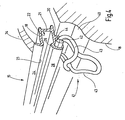
- FIG. 1 the broken-represented rear end 1 of a station wagon or passenger car is illustrated in perspective. It can be seen a cargo space or a cargo bay 2, bounded by a bottom 3 and two side walls, of which only the right side wall 4 can be seen. On the side wall 4 is a rear side window 5. The conclusion to the front of the cargo bay 2 forms a rear seat back 6 of a rear seat 7th
- a Abdeckrollo 8 To cover the cargo bay 2 up a Abdeckrollo 8 is provided.
- To the cover roller 8 includes a cassette 9, which extends beyond the width of the cargo bay 2 behind the rear seat back 6.
- the cassette 9 is located in receiving pockets 10 which are present in the window reveal of the rear side fastener 5.
- the cassette 9 opens at a pull-out slot 11 in the direction of the rear rear opening of the loading bay 2.
- an unrecognizable winding shaft is rotatably mounted in the usual manner, to which a roller blind 12 is attached with one edge.
- the winding shaft is biased in the sense of winding the blind sheet 2 on the winding shaft.
- a pull-out profile 13 with a handle 14 is provided at the free end of the roller blind.
- To the cover roller 8 also includes two guide rails, which are arranged below the reveal of the rear side window 5. Because of the truncated representation, only the guide rail 15 can be seen. This guide rail 15 extends, as the mirror image arranged, not visible, guide rail, on the left side of the vehicle from the cassette 9 to the rear tailgate opening of the motor vehicle. It runs approximately horizontally and is straight.
- the guide rail 15 also has anchoring means 16, by means of which cargo, for example a shopping bag 17, is to be anchored in the cargo bay 2.
- the guide rails 15 are integrated in lateral interior trim parts 18, which extend below the bottom edge of the window up to the bottom 3.
- Fig. 2 shows an enlarged perspective view of the guide rail 15. It consists of an aluminum extruded profile, which is suitably anodized, for example.
- the guide rail 15 has two mutually parallel profile sections 19 and 20, which are connected by a perpendicular thereto extending profile section 21 with each other. These profile sections 19, 20 and 21 form a groove chamber 22 of a guide groove 23, in which the extension profile 13 slides.
- the profile section 19 is provided with an upwardly projecting bar 24, wherein at the transition point between the bar 24 and the profile section 19, a rib 25 is formed, which projects opposite the profile section 19, as shown, downwards.
- the lower profile section 20 is provided at its free end with an upwardly projecting rib 26 which forms a groove slot 27 of the guide groove 23 together with the rib 25.
- an undercut groove for guiding the extension profile 13 since the width of the groove slot 27 is smaller than the width of the groove chamber 23, measured in the vertical direction.
- the rib 26 is followed by a downwardly leading bar 28, which contains anchoring openings 29 at regular intervals.
- a support strip 30 is formed which extends from the bottom of the lower profile section 20 in the vicinity of the rib 26. From this point, it first leads vertically downwards and merges at the lower free end into a leg 31 whose free end is connected to the lower edge of the strip 28.
- the strip 28 and the support strip 30 form a cavity 32 with triangular cross-section, which runs through the length of the guide rail 15.
- the guide rail 15 rests on the lower interior trim part 18, which is contoured accordingly. From the top of the guide rail 15 is another interior trim part 34 starts, which starts at the bar 24 and extends to the window 5.
- the anchoring of the guide rail 15 is not shown further, because it is understood that the guide rail is stably fixed to the sheet metal body in order to initiate the forces occurring in the body can.
- the openings 29 of the bar 16 act as anchoring members, in which further anchoring members, for example in the form of brackets 35 can be hung.
- brackets 35 which are located approximately at the height of the lower edge of the side window 5
- bags or bags 17 can be kept free-hanging with their handle.
- the anchoring means ensure that the cargo attached thereto has only limited freedom of movement within the cargo bay 2.
- the lower edge of such a network can be fixed in a arranged in the bottom 3 of the cargo bay 2 anchoring rail 36.
- the anchoring rail 36 has a ladder-like shape.
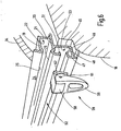
- FIGS. 3 and 4 show another embodiment of the anchoring means 16. While in the anchoring means 16 of FIGS. 1 and 2 discrete anchoring positions are given by the openings 29, in the embodiment of FIGS. 3 and 4, a continuous adjustability given.
- FIGS. 3 and 4 For explanation of FIGS. 3 and 4, the same reference numerals are used as in the embodiment of FIGS. 1 and 2, as far as it is homologous or functionally identical or similar structures or components.
- the already explained bar 28 is in the embodiment of FIGS. 3 and 4, as shown, to the vehicle side outwardly and inwardly curved, whereby at the back of the bar 28, a rearwardly open groove 37 is formed, which also again from a Nutensch 38 and a groove slot 39 composed.
- the width of the groove chamber 38 is greater than the width of the slot 39, which opens in the direction of the loading bay 2 away towards the outside of the vehicle.
- the groove 37 is not open to the loading book.
- the interior trim part 18 below the guide rail 15 has a step 40 which extends at a distance to the underside of the guide rail 15. This creates below the guide rail 15, a gap through which, a in Fig. 3 illustrated lashing 41 can be inserted.
- To the lashing 41 includes a support member 42 which has the shape of a rod. From the support member 42 go at both ends curved legs 43, which unite at the distal end of the support member 42 to two eyes, as shown in FIG. 4 reveals.
- the length of the support member 42 is slightly larger than the width of the eyelets.
- One of the two eyelets is in use slightly upwards and at the same time forms a hook, while the other eyelet over the edge of the step 40 of the interior trim part 18 is hanging down.
- the support member 42 is provided at 44 with an elastomeric coating.
- the total cross section of the support member including the elastomeric coating 44 provides the support member with an approximately oval or elliptical shape adapted to the shape of the groove chamber 38.
- the lashing 41 For attaching the lashing 41, the lashing in the position shown in Fig. 3, in which the actual eyelets are up, with the support member 42 ahead inserted through the gap between the shoulder 44 and the bottom of the guide rail 15. Then, the oval support member 42 with the uncoated part is inserted in advance through the slot 39 into the groove chamber 38.
- the short axis of the cross section of the support member 42 is smaller than the width of the slot 39.
- the lashing 41 is pivoted about an axis defined by the longitudinal axis of the support member 42 downwardly, whereby the provided with the elastomeric coating 44 portion into the groove chamber 38 inside arrives.
- the elastomeric coating 44 is sized in wall thickness such that the support member 42 jams within the groove chamber 38. The high friction exhibited by the elastomeric coating 44 within the groove chamber 38 prevents the support member 42 from sliding along the groove 37.
- the lashing 41 is thus prevented from sliding in the longitudinal direction of the guide groove 37.
- the elastomeric coating 44 provides only the initial frictional force, so that even under the influence of vibration the lashing 41 can not migrate in the longitudinal direction of the groove 37 under any circumstances.
- FIGS. 5 and 6 show a further embodiment of the arrangement according to the invention. While in the previous embodiment, the locking or jamming of the lashing 41 by pivoting same within the guide groove 37, the embodiment of FIGS. 5 and 6 provides an eccentric.
- the guide rail 15, which in the region of the guide profile for the extension profile 13 in the same way is as in the embodiment of FIGS. 3 and 4 and the embodiment of FIG. 2, now has a provided below the profile section 20 arrangement which forms a groove 37 open towards the front.
- a web 45 extends downwards, the free end of which merges into a horizontally extending leg 46.
- Whose free end is provided with an L-shaped profile 47, which forms an inner edge 48.
- a bar 49 which has a similar profile, as the bar 28 of FIG. 3. Again, this results in an inwardly facing edge 51 which runs parallel and at a distance from the edge 48. Between the two edges 48 and 51, a groove slot 52 is limited, which releases the access to a groove chamber 53.
- the guide groove 37 in the embodiment of FIGS. 5 and 6 to the loading bay 2 is open. This makes it possible to bring the mecanicaldungsteil 18 to directly on the leg 46 of the guide rail 15 can.
- To the lashing 41 includes a nut 54 with two mutually parallel grooves 55 which engage over the two edges 58 and 41 in the inserted state.
- a helical compression spring 56 which concentrically surrounds a plunger 57, the sliding block 54 is resiliently biased away from a base body 58.
- De plunger sits centrally on the nut 54.
- an eye member 59 is hinged on the main body 58.
- a hinge axis 61 is provided to connect the ⁇ senglieds 59 with the main body 58.
- the hinge axis 61 passes through a hole in the main body 58 of the plunger 57th
- the eye member 59 has on the side of the main body 58 on two parallel spaced adjacent eccentric tabs 62, which can be supported on extensions 63 of the main body 58.
- the T-nut 54 is inserted through the slot 52. Then, the entire assembly is rotated about an axis defined by the plunger 57 by 90 ° until the grooves 55 are aligned with the edges 51 and 48. Now, the eye member 49 is pivoted about the horizontally extending hinge axis 61 down to the position of FIG. 5. The eccentric 62 push the hinge axis 61 of the projections 62 in the direction of the guide rail 15 away. During this movement, the plunger 57 is pulled into the housing 58, whereby the T-nut 54 with the grooves 55 on the end edges 48 and 51 jammed.
- a load compartment cover has lateral guide rails for the roller blind or roller blind. These guide rails are additionally provided with anchoring means in order to be able to determine load in the hold so far that the load only a limited movement in the hold can perform.
Abstract
Description
Bei den früheren Kraftfahrzeugen waren die Lade- oder Kofferräume von PKWs üblicherweise nicht ausgekleidet, weshalb genügend Ecken und Nischen vorhanden waren, in denen kleineres Ladegut verstaut werden konnte. Bei den neueren Fahrzeugen bemühen sich die Designer auch um den Lade- und Kofferraum. Er ist üblicherweise heute mit einem teppichbodenähnlichen Belag ausgekleidet. Der Boden ist weitgehend eben und auch im Seitenbereich fehlen taschenförmige Vertiefungen. Die Folge ist, dass kleines Ladegut, das den Ladeboden nicht vollständig ausfüllt, beim Anfahren und Bremsen und auch beim Kurvenfahren auf dem Ladeboden beliebig verrutscht.In the earlier motor vehicles, the loading or luggage compartments of cars were usually not lined, so there were plenty of nooks and crannies in which smaller load could be stowed. In the newer vehicles, the designers also strive for the loading and luggage compartment. It is usually lined today with a carpet-like covering. The bottom is largely flat and pocket-like depressions are also missing in the side area. The result is that small load, which does not completely fill the loading floor, slipping as desired during start-up and braking and also when cornering on the loading floor.
Um dem entgegenzuwirken ist es aus der Praxis bekannt, im Boden des Fahrzeugs leiternähnliche Schienen zu verlegen, die als Verankerungsmittel dienen sollen. In die Sprossen der leiternähnlichen Schienen können Verzurrgurte mit Haken eingehängt werden.To counteract this, it is known from practice to lay ladder-like rails in the floor of the vehicle, which are to serve as anchoring means. Lashing straps with hooks can be hung in the rungs of the ladder-like rails.
Mit einer solchen Verankerungseinrichtung ist es aber jedoch nicht möglich, nicht formstabiles Ladegut wie beispielsweise Einkaufstaschen oder mit Lebensmittel gefüllte Plastiktüten zu fixieren.However, with such anchoring device, it is not possible to fix non-dimensionally stable load such as shopping bags or food filled plastic bags.
Eine Aufteilung des Laderaums in ein kleineres Kompartment ist bei ausschließlich am Boden befindlichen Schienen nicht durchführbar.A division of the hold into a smaller compartment is not feasible in exclusively located on the ground rails.
Darüber hinaus ist es für Kombi-PKW bekannt, die Ladebucht durch eine Plane nach oben hin optisch zu verschließen. Solche Laderaumabdeckungen weisen eine Rollobahn auf, die in einer Kassette an der Rückseite der Rücksitzlehne zu verstauen ist. Hierzu befindet sich in der Kassette eine drehbar gelagerte Wickelwelle, an der die Rollobahn mti einer Kante befestigt.In addition, it is known for estate cars to optically close the cargo bay by a tarpaulin upwards. Such cargo space covers have a roller blind, which is to be stowed in a cassette on the back of the rear seat back. For this purpose, there is a rotatably mounted winding shaft in the cassette, to which the roller blind mti attached an edge.
Zum Aufspannen und Führen der Rollobahn sind üblicherweise unterhalb der Seitenfenster Führungsschienen vorgesehen.For clamping and guiding the roller blind guide rails are usually provided below the side windows.
Bei einer anderen Ausführungsform von Laderaumabdeckungen wird die Plane durch eine Reihe von Spriegeln unterstützt, die ebenfalls in seitlichen Führungsschienen unterhalb der Seitenfenster geführt sind.In another embodiment of load compartment covers, the tarpaulin is supported by a series of hoops which are also guided in lateral guide rails below the side windows.
Ohne weitere Erläuterung zeigt die DE 100 47 542 A1 eine Figur, die zwei Führungsnuten übereinander erkennen lässt, die an einer Laderaumseitenwand ausgebildet sind. Die eine Führungsnut soll dazu vorgesehen sein, die Endstücke eines Auszugsprofils einer Laderraumabdeckung zu führen. Eine weitere Ausnehmung oder Nut gestattet die Halterung von Trennwänden, um einen Lade- oder Kofferraum eines Pkw zu segmentieren.Without further explanation, DE 100 47 542 A1 shows a figure which reveals two guide grooves which are formed on a loading space sidewall. The one guide groove should be intended to guide the end pieces of a pull-out profile of a load compartment cover. Another recess or groove allows the holder of partitions to segment a cargo or trunk of a car.
Ausgehend hiervon ist es Aufgabe der Erfindung ein verbessertes System zum Verzurren und Sichern von Ladegut, insbesondere in der Ladebucht von Kombi-PKW, zu schaffen.Based on this, it is an object of the invention to provide an improved system for lashing and securing cargo, especially in the cargo bay of estate cars.
Diese Aufgabe wird erfindungsgemäß durch die Laderaumabdeckungseinrichtung mit den Merkmalen des Anspruches 1 gelöst.This object is achieved by the load compartment cover device with the features of claim 1.
Eine Laderaumabdeckungseinrichtung ist mit einem Abdeckelement versehen, das die Gestalt einer Rollobahn oder einer Plane eines Raffrollos aufweisen kann. Zum Führen dieses Abdeckelementes beim Übergang von der Offen- in die Schließstellung und umgekehrt sind seitlich der Ladebucht zwei längs der Ladebucht verlaufende Schienen vorgesehen. An wenigstens einer der Schienen sind Verankerungsmittel für ein in der Ladebucht enthaltenes Ladegut ausgebildet.A load compartment cover device is provided with a cover element, which may have the shape of a roller blind or a tarpaulin of a Roman blind. To guide this cover member in the transition from the open to the closed position and vice versa side of the cargo bay two rails extending along the loading bay are provided. Anchoring means for a cargo contained in the cargo bay are formed on at least one of the rails.
Zweckmäßigerweise laufen die Führungsschienen über die gesamte Tiefe der Ladebucht durch.Appropriately, the guide rails run over the entire depth of the cargo bay.
Zu dem Verankerungsmittel gehört eine mit der Schiene einstückige Leiste, die über die Länge der Schiene durchläuft. Die Leiste bildet zusammen mit der Schiene eine Nut, die sich in die Richtung auf die Ladebucht oder von der Ladebucht weg öffnet.The anchoring means include a bar integral with the rail which traverses the length of the rail. The bar together with the rail a groove that opens in the direction of the cargo bay or away from the cargo bay.
Die Nut ist eine hinterschnittene Nut.The groove is an undercut groove.
Auf diese Weise wird ein Verankerungsmittel geschaffen, das vom Boden des Laderaums oder der Ladebucht deutlichen beabstandet ist. An diesem Verankerungsmittel lassen sich nun wegen des Abstandes zum Boden auch Tüten, Taschen und dergleichen einhängen.In this way, an anchoring means is provided, which is evident from the bottom of the hold or the cargo bay is spaced. At this anchoring means can now hang because of the distance to the floor and bags, bags and the like.
Wenn derartige Verankerungsmittel auf beiden Seiten des Fahrzeugs vorhanden sind, besteht die Möglichkeit, den Laderaum unterhalb der Fensterkante in Querrichtung zu unterteilen. Hierzu können gegebenenfalls noch weitere Schienen im Boden des Fahrzeugs verwendet werden, wie dies bereits an sich bekannt ist.If such anchoring means are present on both sides of the vehicle, it is possible to divide the cargo space below the window edge in the transverse direction. For this purpose, if necessary, further rails in the floor of the vehicle can be used, as is already known per se.
Die Schienen können für das Abdeckelement in der bereits bekannten Weise mit den hinterschnittenen Führungsnuten ausgestattet sein, oder auch als einfaches, nach oben offenes Profil, das lediglich eine glatte, schmale Führungsbahn bildet, aus dem das Auszugsprofil für das Abdeckelement jederzeit nach oben aushebbar ist.The rails may be equipped for the cover in the manner already known with the undercut guide grooves, or as a simple, upwardly open profile, which forms only a smooth, narrow track, from which the pull-out profile for the cover is always raised upwards.
Das Verankerungsmittel kann ein Verzurrglied umfassen, das mit der Leiste oder der Nut verstellbar verbunden ist. Hierbei kann es sich um eine Verzurröse oder einen Verzurrhaken handeln.The anchoring means may comprise a lanyard which is adjustably connected to the strip or groove. This can be a lashing eye or a lashing hook.
Zweckmäßigerweise ist das Verzurrglied mit einer Bremseinrichtung versehen, die verhindert, dass das Verzurrglied längs der Schiene bewegt wird, wenn Beschleunigungs- oder Bremskräfte in Längsrichtung der Schiene auf das Ladegut einwirken. Die Bremseinrichtung kann von einem elastomeren Stück gebildet sein oder eine Exzenterklemmeinrichtung umfassen.Conveniently, the lashing member is provided with a braking device which prevents the lashing member is moved along the rail when acceleration or braking forces act on the load in the longitudinal direction of the rail. The braking device may be formed by an elastomeric piece or comprise an eccentric clamping device.
Im Übrigen sind Weiterbildungen der Erfindung Gegenstand von Unteransprüchen.Incidentally, developments of the invention are the subject of subclaims.
Beim Lesen der Figurenbeschreibung wird ferner klar, dass eine Reihe von Abwandlungen möglich sind.When reading the description of the figures, it is further clear that a number of modifications are possible.
In der Zeichnung von Ausführungsbeispiele des Gegenstandes der Erfindung dargestellt. Es zeigen:
- Fig. 1
- eine Heckpartie eines Kombi-PKW unter Veranschaulichung der neuen Laderaumabdeckungseinrichtung, in einer aufgebrochenen perspektivischen Darstellung,
- Fig. 2
- die Führungsschiene der Laderaumabdeckeinrichtung nach Fig. 1, in einer vergrößerten perspektivischen Darstellung,
- Fig. 3 und 4
- ein erfindungsgemäßes Ausführungsbeispiel für die Schiene der Laderaumabdeckungseinrichtung nach Fig. 1 mit einem von unten einsetzbaren Verankerungsglied und
- Fig. 5 und 6
- ein weiteres erfindungsgemäßes Ausführungsbeispiel der Führungsschiene der Laderaumabdeckeinrichtung nach Fig. 1, mit einem Verankerungsglied mit Exzenterspannung.
- Fig. 1
- a rear end of a station wagon illustrating the new load compartment cover device, in a broken perspective view,
- Fig. 2
- 1 shows the guide rail of the load compartment covering device according to FIG. 1, in an enlarged perspective view,
- 3 and 4
- an inventive embodiment of the rail of the luggage compartment cover device of FIG. 1 with an insertable from below anchoring member and
- FIGS. 5 and 6
- another inventive embodiment of the guide rail Laderaumabdeckeinrichtung of FIG. 1, with an anchoring member with eccentric.
In Fig. 1 ist die aufgebrochen dargestellte Heckpartie 1 eines Kombi-Kraftfahrzeuges oder Personenkraftwagens perspektivisch veranschaulicht. Es ist ein Laderaum oder eine Ladebucht 2 zu erkennen, die von einem Boden 3 sowie zwei Seitenwänden begrenzt, von denen nur die rechte Seitenwand 4 erkennbar ist. Über der Seitenwand 4 befindet sich ein hinteres Seitenfenster 5. Der Abschluss nach vorne der Ladebucht 2 bildet eine Rücksitzlehne 6 einer Rücksitzbank 7.In Fig. 1, the broken-represented rear end 1 of a station wagon or passenger car is illustrated in perspective. It can be seen a cargo space or a cargo bay 2, bounded by a
Zum Abdecken der Ladebucht 2 nach oben ist ein Abdeckrollo 8 vorgesehen. Zu dem Abdeckrollo 8 gehört eine Kassette 9, die sich über die Breite der Ladebucht 2 hinter der Rücksitzlehne 6 erstreckt. Die Kassette 9 liegt in Aufnahmetaschen 10, die in der Fensterleibung des hinteren Seitenfesters 5 vorhanden sind. Die Kassette 9 öffnet sich an einem Auszugsschlitz 11 in Richtung auf die hintere Hecköffnung der Ladebucht 2. Innerhalb der Kassette 9 ist in der üblichen Weise eine nicht erkennbare Wickelwelle drehbar gelagert, an der mit einer Kante eine Rollobahn 12 befestigt ist.To cover the cargo bay 2 up a Abdeckrollo 8 is provided. To the cover roller 8 includes a
Mittels eines nicht dargestellten Federmotors wird die Wickelwelle im Sinne des Aufwickelns der Rollobahn 2 auf die Wickelwelle vorgespannt.By means of a spring motor, not shown, the winding shaft is biased in the sense of winding the blind sheet 2 on the winding shaft.
Um die Rollobahn 2 entgegen der Wirkung des Federmotors abzuziehen, ist an dem freien Ende der Rollobahn ein Auszugsprofil 13 mit einem Handgriff 14 vorhanden.In order to subtract the roller blind 2 against the action of the spring motor, a pull-out
Zu dem Abdeckrollo 8 gehören ferner zwei Führungsschienen, die unterhalb der Leibung des hinteren Seitenfensters 5 angeordnet sind. Wegen der abgeschnittenen Darstellung ist lediglich die Führungsschiene 15 zu erkennen. Diese Führungsschiene 15 erstreckt sich, wie die spiegelbildlich angeordnete, nicht sichtbare, Führungsschiene, auf der linken Fahrzeugseite von der Kassette 9 bis zu der hinteren Heckklappenöffnung des Kraftfahrzeuges. Sie verläuft etwa horizontal und ist gerade.To the cover roller 8 also includes two guide rails, which are arranged below the reveal of the
Die Führungsschiene 15 weist außerdem Verankerungsmittel 16 auf, mit deren Hilfe Ladegut, beispielsweise eine Einkaufstasche 17, in der Ladebucht 2 zu verankern ist.The
Die Fhrungsschienen 15 sind in seitlichen Innenverkleidungsteilen 18 integriert, die sich unterhalb der Fensterunterkante bis zu dem Boden 3 erstrecken.The guide rails 15 are integrated in lateral interior
Die Funktionsweise der Laderaumabdeckeinrichtung 8 braucht ansonsten nicht weiter erläutert zu werden, da sie für sich genommen, bekannt ist.The operation of the Laderaumabdeckeinrichtung 8 need not be explained otherwise, since it is taken alone known.
Fig. 2 zeigt in einer vergrößerten perspektivischen Darstellung die Führungsschiene 15. Sie besteht aus einem Aluminiumstrangpressprofil, das beispielsweise geeignet eloxiert ist.Fig. 2 shows an enlarged perspective view of the
Die Führungsschiene 15 weist zwei parallel zueinander verlaufende Profilabschnitte 19 und 20 auf, die durch einen rechtwinklig dazu verlaufenden Profilabschnitt 21 miteinander verbunden sind. Diese Profilabschnitte 19, 20 und 21 bilden eine Nutenkammer 22 einer Führungsnut 23, in der das Auszugsprofil 13 gleitet.The
An seinem freien Ende ist der Profilabschnitt 19 mit einer nach oben aufragenden Leiste 24 versehen, wobei an der Übergangsstelle zwischen der Leiste 24 und dem Profilabschnitt 19 eine Rippe 25 entsteht, die gegenüber dem Profilabschnitt 19, wie gezeigt, nach unten vorspringt.At its free end, the
Der untere Profilabschnitt 20 ist an seinem freien Ende mit einem nach oben aufragenden Rippe 26 versehen, die zusammen mit der Rippe 25 einen Nutenschlitz 27 der Führungsnut 23 bildet. Auf diese Weise entsteht eine hinterschnittene Nut zur Führung des Auszugsprofils 13, da die Breite des Nutschlitzes 27 kleiner ist als die Weite der Nutenkammer 23, gemessen in der vertikalen Richtung.The
An die Rippe 26 schließt sich eine nach unten führende Leiste 28 an, die in regelmäßigen Abstand Verankerungsöffnungen 29 enthält.The
Um die Leiste 28 auszusteifen, ist eine Stützleite 30 angeformt die von der Unterseite des unteren Profilabschnittes 20 in der Nähe der Rippe 26 ausgeht. Von dieser Stelle führt sie zunächst vertikal nach unten und geht am unteren freien Ende in einen Schenkel 31 über, dessen freies Ende mit der Unterkante der Leiste 28 verbunden ist. Die Leiste 28 und die Stützleiste 30 bilden einen Hohlraum 32 mit dreieckförmigem Querschnitt, der über die Länge der Führungsschiene 15 durchläuft.To stiffen the
Die Führungsschiene 15 liegt auf dem unteren Innenverkleidungsteil 18 auf, das entsprechen konturiert ist. Von der Oberseite der Führungsschiene 15 geht ein weiteres Innenverkleidungsteil 34 aus, das an der Leiste 24 beginnt und bis zu dem Fenster 5 reicht.The
Die Verankerung der Führungsschiene 15 ist nicht weiter gezeigt, denn es versteht sich, dass die die Führungsschiene an der Blechkarosserie stabil befestigt ist um die auftretenden Kräfte in die Karosserie einleiten zu können.The anchoring of the
Die Öffnungen 29 der Leiste 16 wirken als Verankerungsglieder, in die weitere Verankerungsglieder, beispielsweise in Gestalt von Bügeln 35 eingehängt werden können. Mit Hilfe dieser auskragenden Bügel 35, die sich etwa auf der Höhe der Unterkante der Seitenscheibe 5 befinden, können Taschen oder Beutel 17 mit ihrem Henkel freihängend aufbewahrt werden. Durch diese Bügel werden die Tüten, Beutel oder Taschen 17 daran gehindert, sich frei in der Ladebucht 2 hin und her bewegen zu können, wenn sie aufgrund der Fahrbewegung des Kraftfahrzeuges Beschleunigungskräften ausgesetzt sind. Die Verankerungsmittel sorgen dafür, dass das daran befestigte Ladegut lediglich eine begrenzte Bewegungsfreiheit innerhalb der Ladebucht 2 hat.The
Da die Öffnungen 29, die im gezeigten Ausführungsbeispiel etwa quadratisch gestaltet sind, in den dahinter befindlichen Hohlraum 32 münden, können geeignete Aufhängebügel 35, wie der in Fig. 1 gezeigt, in den Öffnungen 98 verhakt werden.Since the
Da sich zwei Führungsschienen 15, wie sie in Fig. 2 gezeigt sind, bezüglich in der Ladebucht 2 gegenüber befinden, besteht die Möglichkeit, zwischen ihnen Netze zu spannen. Die Unterkante eines solchen Netzes kann in eine im Boden 3 der Ladebucht 2 angeordnete Verankerungsschiene 36 festgelegt sein. Die Verankerungsschiene 36 hat eine leiternähnliche Gestalt.Since there are two
Die Fig. 3 und 4 zeigen ein anderes Ausführungsbeispiel für das Verankerungsmittel 16. Während bei dem Verankerungsmittel 16 nach den Fig. 1 und 2 diskrete Verankerungspositionen durch die Öffnungen 29 vorgegeben sind, ist bei der Ausführungsform nach den Fig. 3 und 4 eine kontinuierliche Verstellbarkeit gegeben.3 and 4 show another embodiment of the anchoring means 16. While in the anchoring means 16 of FIGS. 1 and 2 discrete anchoring positions are given by the
Zur Erläuterung der Fig. 3 und 4 werden dieselben Bezugszeichen verwendet, wie bei dem Ausführungsbeispiel nach den Fig. 1 und 2, soweit es sich um homologe oder funktionsgleiche oder -ähnliche Strukturen oder Bauelemente handelt.For explanation of FIGS. 3 and 4, the same reference numerals are used as in the embodiment of FIGS. 1 and 2, as far as it is homologous or functionally identical or similar structures or components.
Die bereits erläuterte Leiste 28 ist bei dem Ausführungsbeispiel nach den Fig. 3 und 4, wie gezeigt, zur Fahrzeugseite nach außen und einwärts gekrümmt, wodurch an der Rückseite der Leiste 28 eine nach hinten offene Nut 37 entsteht, die sich ebenfalls wieder aus einer Nutenkammer 38 und einem Nutenschlitz 39 zusammensetzt. Die Weite der Nutenkammer 38 ist größer als die Weite des Schlitzes 39, der sich in Richtung von der Laderaumbucht 2 weg in Richtung zu der Außenseite des Fahrzeugs öffnet. Damit ist die Nut 37 nicht zu der Ladebuch hin offen.The already explained
Der Nutenschlitz 37 ist somit verdeckt. Um dennoch Zugang zu der Nut 37 zu erhalten, weist das Innenverkleidungsteil 18 unterhalb der Führungsschiene 15 eine Stufe 40 auf, die im Abstand zu der Unterseite der Führungsschiene 15 verläuft. Hierdurch entsteht unterhalb der Führungsschiene 15 ein Spalt, durch den hindurch, ein in der Fig. 3 veranschaulichte Verzurröse 41 eingeführt werden kann.The
Zu der Verzurröse 41 gehört ein Tragglied 42, das die Form eines Stabes aufweist. Von dem Tragglied 42 gehen an beiden Enden geschwungene Schenkel 43 aus, die sich an dem von dem Tragglied 42 abliegenden Ende zu zwei Ösen vereinigen, wie dies Fig. 4 erkennen lässt. Die Länge des Tragglieds 42 ist etwas größer als die Breite der Ösen. Eine der beiden Ösen steht im Gebrauchszustand etwas nach oben und bildet gleichzeitig einen Haken, während die andere Öse über die Kante der Stufe 40 des Innenverkleidungsteils 18 nach unten hängt.To the lashing 41 includes a
Um ein Verrutschen der Verzurröse 41 längs der Nut 37 zu verhindern, ist das Tragglied 42 bei 44 mit einem elastomeren Belag versehen. Der Gesamtquerschnitt des Traggliedes einschließlich der elastomeren Beschichtung 44 verleiht dem Tragglied eine etwa ovale oder elliptische Gestalt, die an die Gestalt der Nutenkammer 38 angepasst ist.In order to prevent slippage of the lashing 41 along the
Zum Einhängen der Verzurröse 41 wird die Verzurröse in der in Fig. 3 gezeigten Position, in der die eigentlichen Ösen nach oben stehen, mit dem Tragglied 42 voraus durch den Spalt zwischen der Schulter 44 und der Unterseite der Führungsschiene 15 eingeführt. Sodann wird das ovale Tragglied 42 mit dem nichtbeschichteten Teil voraus durch den Schlitz 39 in die Nutenkammer 38 eingeführt. Die kurze Achse des Querschnitts des Tragglieds 42 ist kleiner als die Breite des Schlitzes 39. Anschließend wird die Verzurröse 41 um eine durch die Längsachse des Tragglieds 42 definierter Achse nach unten geschwenkt, wodurch der mit der elastomeren Beschichtung 44 versehene Abschnitt in die Nutenkammer 38 hinein gelangt. Die elastomere Beschichtung 44 ist in der Wandstärke so bemessen, dass sich das Tragglied 42 innerhalb der Nutenkammer 38 verklemmt. Die hohe Reibung, die die elastomere Beschichtung 44 innerhalb der Nutenkammer 38 zeigt, verhindert, dass das Tragglied 42 längs der Nut 37 gleiten kann.For attaching the lashing 41, the lashing in the position shown in Fig. 3, in which the actual eyelets are up, with the
Sobald an den freien Enden der Verzurröse 41 eine Kraft angreift, die in Richtung parallel zu der Führungsschiene 15 wirkt, verstärkt die hierdurch hervorgerufene Kippkraft den Reibschluss des Traggliedes 42 innerhalb der Nutenkammer 38. Es kommt zu einem Effekt wie er auftritt, wenn sich eine Schublade in einer Führung verklemmt. Hierbei tritt eine Selbstverstärkung auf in dem Sinne, dass mit Erhöhung der angreifenden Kraft auch die Reibschlusskraft verstärkt wird.As soon as a force acts on the free ends of the lashing 41, which acts in the direction parallel to the
Die Verzurröse 41 ist damit daran gehindert, in Längsrichtung der Führungsnut 37 zu gleiten. Die elastomere Beschichtung 44 liefert lediglich die initiale Reibkraft, damit auch unter der Einwirkung von Erschütterungen die Verzurröse 41 auf keinen Fall in Längsrichtung der Nut 37 wandern kann.The lashing 41 is thus prevented from sliding in the longitudinal direction of the
Zum Verschieben oder Herausnehmen muss der Benutzer die Verzurröse aus der Stellung nach Fig. 4 wieder nach oben schwenken, bis die elastomere Beschichtung 44, die sich über die Länge des Traggliedes 42 fortsetzt, in Richtung auf den Nutenschlitz 39 zeigt. Damit ist die Blockade aufgehoben und die Verzurröse 41 lässt sich versetzen. An der gewünschten Zielposition wird sie durch Herunterschwenken wieder verankert.To move or remove the user must swing the lashing from the position shown in FIG. 4 up again until the
Aus der Funktionsbeschreibung ergibt sich auch an welcher Stelle die elastomere Beschichtung 44 angeordnet sein muss: Sie befindet sich bei geklemmter Verzurröse 41 an jener Stelle, die bei dem Tragglied 42 nach oben zeigt, womit die Unterseite des Traggliedes, die auf der in Fig. 3 unteren Bereich der Wand der Kammer 37 aufliegt, einen rein metallischen Kontakt liefert, der nicht nachgibt.The description of the function also reveals the point at which the
Die Figuren 5 und 6 zeigen ein weiteres Ausführungsbeispiel der erfindungsgemäßen Anordnung. Während bei dem vorigen Ausführungsbeispiel die Verriegelung oder Verklemmung der Verzurröse 41 durch Schwenken derselben innerhalb der Führungsnut 37 erfolgte, sieht das Ausführungsbeispiel nach den Fig. 5 und 6 eine Exzenterspannung vor.Figures 5 and 6 show a further embodiment of the arrangement according to the invention. While in the previous embodiment, the locking or jamming of the lashing 41 by pivoting same within the
Die Führungsschiene 15, die im Bereich des Führungsprofils für das Auszugsprofil 13 in der gleichen Weise gestaltet ist wie bei dem Ausführungsbeispiel nach den Fig. 3 und 4 bzw. dem Ausführungsbeispiel nach Fig. 2, weist nunmehr eine unterhalb des Profilabschnitts 20 vorgesehene Anordnung auf, die eine nach vorne offene Nut 37 bildet. Hierzu geht unterhalb des unteren Profilabschnitts 20 ein Steg 45 nach unten weg, dessen freies Ende in einen horizontal verlaufenden Schenkel 46 übergeht. Dessen freies Ende ist mit einem L-förmigen Profil 47 versehen, das eine innen liegende Kante 48 bildet.The
Im oberen Teil geht die Rippe 26 in eine Leiste 49 über, die ein ähnliches Profil aufweist, wie die Leiste 28 nach Fig. 3. Auch hierdurch entsteht wiederum eine nach innen zeigende Kante 51, die parallel und im Abstand zu der Kante 48 läuft. Zwischen den beiden Kanten 48 und 51, wird ein Nutenschlitz 52 begrenzt, der den Zugang zu einer Nutenkammer 53 freigibt.In the upper part of the
Wie gezeigt, ist die Führungsnut 37 bei dem Ausführungsbeispiel nach den Fig. 5 und 6 zur Ladebucht 2 hin offen. Dies ermöglicht es, das Innenverkeidungsteil 18 bis unmittelbar an den Schenkel 46 der Führungsschiene 15 heranbringen zu können.As shown, the
Zu der Verzurröse 41 gehört ein Nutenstein 54 mit zwei parallel zueinander verlaufenden Nuten 55, die im eingesetzten Zustand die beiden Kanten 58 und 41 übergreifen. Mittels eine Schraubendruckfeder 56, die einen Stößel 57 konzentrisch umgibt, wird Nutenstein 54 federelastisch von einem Grundkörper 58 weg vorgespannt. De Stößel sitzt mittig auf dem Nutenstein 54. An dem Grundkörper 58 ist ein Ösenglied 59 anscharniert. Zur Verbindung des Ösenglieds 59 mit dem Grundkörper 58 ist eine Scharnierachse 61 vorgesehen. Die Scharnierachse 61 führt durch eine in dem Grundkörper 58 befindliche Bohrung des Stößels 57.To the lashing 41 includes a
Das Ösenglied 59 weist auf der Seite des Grundkörpers 58 zwei parallel mit Abstand nebeneinander verlaufende Exzenterlaschen 62 auf, die sich an Fortsätzen 63 des Grundkörpers 58 abstützen können.The
Die Funktionsweise der Verzurröse 41 im Zusammenspiel mit der Führungsschiene 50 ergibt sich aus einer Zusammenschau der Fig. 5 und 6:The operation of the lashing 41 in conjunction with the guide rail 50 results from a synopsis of FIGS. 5 and 6:
In der in Fig. 5 gezeigten Stellung wird der T-Nutenstein 54 durch den Nutenschlitz 52 eingeführt. Sodann wird die gesamte Anordnung um eine durch den Stößel 57 definierte Achse um 90° gedreht, bis die Nuten 55 mit den Kanten 51 und 48 fluchten. Nunmehr wird das Ösenglied 49 um die hierzu horizontal verlaufende Scharnierachse 61 nach unten geschwenkt, in die Stellung nach Fig. 5. Die Exzenterlaschen 62 schieben dabei die Scharnierachse 61 von den Fortsätzen 62 in Richtung von der Führungsschiene 15 weg. Bei dieser Bewegung wird der Stößel 57 in das Gehäuse 58 hineingezogen, womit sich der T-Nutenstein 54 mit den Nuten 55 auf den Stirnkanten 48 und 51 verklemmt.In the position shown in FIG. 5, the T-
Zum Herausnehmen wird die Sache in der umgekehrten Richtung bewegt.To remove, the thing is moved in the opposite direction.
Eine Laderaumabdeckung weist für die Rollobahn oder Rolloplane seitliche Führungsschienen auf. Diese Führungsschienen sind zusätzlich mit Verankerungsmittel versehen, um Ladegut in dem Laderaum soweit festlegen zu können, dass das Ladegut lediglich eine begrenzte Bewegung in dem Laderaum vollführen kann.A load compartment cover has lateral guide rails for the roller blind or roller blind. These guide rails are additionally provided with anchoring means in order to be able to determine load in the hold so far that the load only a limited movement in the hold can perform.
Claims (13)
- Luggage area covering arrangement (8) for motor vehicles for closing off a luggage compartment (2) contained in a motor vehicle from view from above, with a covering element (12), which can be moved out of a position closing the luggage compartment (2) into a position, in which the luggage compartment (2) is at least partially accessible from above,
with two rails (15), which run along the luggage compartment (2) and are arranged to hold the covering element (12) in the position, in which the luggage compartment (2) is closed off from view, for which purpose each rail (15) includes a groove (23), and
with at least one groove (37, 53) provided in at least one of the rails (15) as anchoring element (16) for at least one luggage item (17) contained in the luggage compartment (2), wherein the further groove (37, 53) is an undercut groove. - Arrangement according to Claim 1, characterised in that the two rails (15) have different cross-sectional profiles.
- Arrangement according to Claim 1, characterised in that the rails (15) extend over the length of the luggage compartment (2).
- Arrangement according to Claim 1, characterised in that the two rails (15) have the same cross-sectional profiles.
- Arrangement according to Claim 1, characterised in that at least one of the rails (15) forms an upwardly open guide profile for the covering element (12).
- Arrangement according to Claim 1, characterised in that the anchoring element (16) comprises at least one locally restricted locking element (29).
- Arrangement according to Claim 1, characterised in that the further groove (53) opens towards the luggage compartment (2).
- Arrangement according to Claim 1, characterised in that the further groove (37) opens away from the luggage compartment (2).
- Arrangement according to Claim 1, characterised in that the anchoring element (16) includes a locking element (41), which is adjustably connected to the strip (28) or the groove (37, 53).
- Arrangement according to Claim 9, characterised in that the locking element (41) is a securing eye or a locking hook.
- Arrangement according to Claim 9, characterised in that the locking element (41) is provided with a brake means (44, 54).
- Arrangement according to Claim 11, characterised in that the brake means comprises an elastomer piece or an elastomer coating (44).
- Arrangement according to Claim 1, characterised in that the brake means comprises an eccentric clamping means (54).
Priority Applications (1)
| Application Number | Priority Date | Filing Date | Title |
|---|---|---|---|
| EP06017120A EP1724154B1 (en) | 2003-10-24 | 2004-10-06 | Load compartment cover with tying means |
Applications Claiming Priority (2)
| Application Number | Priority Date | Filing Date | Title |
|---|---|---|---|
| DE10349936A DE10349936A1 (en) | 2003-10-24 | 2003-10-24 | Load compartment cover with lashing devices |
| DE10349936 | 2003-10-24 |
Related Child Applications (1)
| Application Number | Title | Priority Date | Filing Date |
|---|---|---|---|
| EP06017120A Division EP1724154B1 (en) | 2003-10-24 | 2004-10-06 | Load compartment cover with tying means |
Publications (3)
| Publication Number | Publication Date |
|---|---|
| EP1526039A2 EP1526039A2 (en) | 2005-04-27 |
| EP1526039A3 EP1526039A3 (en) | 2005-08-24 |
| EP1526039B1 true EP1526039B1 (en) | 2007-02-14 |
Family
ID=34384482
Family Applications (2)
| Application Number | Title | Priority Date | Filing Date |
|---|---|---|---|
| EP06017120A Not-in-force EP1724154B1 (en) | 2003-10-24 | 2004-10-06 | Load compartment cover with tying means |
| EP04023757A Not-in-force EP1526039B1 (en) | 2003-10-24 | 2004-10-06 | Load compartment cover with tying means |
Family Applications Before (1)
| Application Number | Title | Priority Date | Filing Date |
|---|---|---|---|
| EP06017120A Not-in-force EP1724154B1 (en) | 2003-10-24 | 2004-10-06 | Load compartment cover with tying means |
Country Status (4)
| Country | Link |
|---|---|
| EP (2) | EP1724154B1 (en) |
| AT (2) | ATE384638T1 (en) |
| DE (3) | DE10349936A1 (en) |
| ES (2) | ES2299126T3 (en) |
Cited By (1)
| Publication number | Priority date | Publication date | Assignee | Title |
|---|---|---|---|---|
| DE102018219794A1 (en) | 2018-11-19 | 2020-05-20 | Volkswagen Aktiengesellschaft | Fastening unit for fastening an object, fastening system, method for producing a fastening unit and motor vehicle |
Families Citing this family (12)
| Publication number | Priority date | Publication date | Assignee | Title |
|---|---|---|---|---|
| SE527584C2 (en) * | 2005-05-18 | 2006-04-18 | Gm Global Tech Operations Inc | Set of baggage holders forms guide path in cross sectional plane having curve corresponding to shape of engaging portion of holding unit |
| DE102006010114A1 (en) * | 2006-02-28 | 2007-08-30 | Bos Gmbh & Co. Kg | Motor vehicle interior with a room cutout |
| DE102006049787B4 (en) * | 2006-10-21 | 2012-03-08 | Audi Ag | Device for holding objects |
| CZ302167B6 (en) | 2007-12-19 | 2010-11-24 | Škoda Auto a. s. | Suspension system of vehicle luggage compartment |
| CZ305656B6 (en) * | 2008-12-18 | 2016-01-27 | Ĺ koda Auto a. s. | Vehicle baggage compartment suspension system |
| CZ305346B6 (en) * | 2009-02-23 | 2015-08-12 | Ĺ koda Auto a. s. | Vehicle luggage compartment cradle work |
| GB2472654A (en) * | 2009-08-15 | 2011-02-16 | Bentley Motors Ltd | A retention system |
| DE102009043767A1 (en) * | 2009-09-30 | 2011-03-31 | GM Global Technology Operations, Inc., Detroit | Fastening system for fastening objects to a backrest of a motor vehicle seat |
| US9056950B2 (en) | 2010-07-23 | 2015-06-16 | Ticona Gmbh | Composite polymeric articles formed from extruded sheets containing a liquid crystal polymer |
| US10189413B2 (en) * | 2017-05-31 | 2019-01-29 | GM Global Technology Operations LLC | Adjustable tambour cargo deck for a vehicle |
| FR3067675B1 (en) * | 2017-06-19 | 2019-08-02 | Treves Products, Services & Innovation | SYSTEM FOR ACTUATING THE LOCKING POSITION OF A CARGO LUGGAGE COMPARTMENT LUGGAGE COVER TRAVERSE |
| DE102020113556B3 (en) * | 2020-05-19 | 2021-10-28 | Humbaur Gmbh | Drop side of a commercial vehicle, lashing element and lashing arrangement |
Family Cites Families (4)
| Publication number | Priority date | Publication date | Assignee | Title |
|---|---|---|---|---|
| US5685592A (en) * | 1995-12-21 | 1997-11-11 | United Technologies Automotive, Inc. | Cargo compartment cover and item support assembly |
| DE10047541A1 (en) * | 2000-07-05 | 2002-01-31 | Bos Gmbh | Loading space for a motor vehicle |
| DE50113567D1 (en) * | 2000-07-05 | 2008-03-20 | Bos Gmbh | LOADING AREA FOR A MOTOR VEHICLE |
| DE10241925A1 (en) * | 2002-09-10 | 2004-04-01 | Adam Opel Ag | Vehicle with holding devices for accessories |
-
2003
- 2003-10-24 DE DE10349936A patent/DE10349936A1/en not_active Withdrawn
-
2004
- 2004-10-06 DE DE502004006090T patent/DE502004006090D1/en active Active
- 2004-10-06 AT AT06017120T patent/ATE384638T1/en not_active IP Right Cessation
- 2004-10-06 ES ES06017120T patent/ES2299126T3/en active Active
- 2004-10-06 EP EP06017120A patent/EP1724154B1/en not_active Not-in-force
- 2004-10-06 AT AT04023757T patent/ATE353793T1/en not_active IP Right Cessation
- 2004-10-06 DE DE502004002893T patent/DE502004002893D1/en active Active
- 2004-10-06 ES ES04023757T patent/ES2279272T3/en active Active
- 2004-10-06 EP EP04023757A patent/EP1526039B1/en not_active Not-in-force
Cited By (1)
| Publication number | Priority date | Publication date | Assignee | Title |
|---|---|---|---|---|
| DE102018219794A1 (en) | 2018-11-19 | 2020-05-20 | Volkswagen Aktiengesellschaft | Fastening unit for fastening an object, fastening system, method for producing a fastening unit and motor vehicle |
Also Published As
| Publication number | Publication date |
|---|---|
| EP1526039A3 (en) | 2005-08-24 |
| EP1724154A1 (en) | 2006-11-22 |
| ATE353793T1 (en) | 2007-03-15 |
| DE10349936A1 (en) | 2005-06-16 |
| ES2299126T3 (en) | 2008-05-16 |
| EP1724154B1 (en) | 2008-01-23 |
| DE502004006090D1 (en) | 2008-03-13 |
| ES2279272T3 (en) | 2007-08-16 |
| ATE384638T1 (en) | 2008-02-15 |
| EP1526039A2 (en) | 2005-04-27 |
| DE502004002893D1 (en) | 2007-03-29 |
Similar Documents
| Publication | Publication Date | Title |
|---|---|---|
| DE3819766C1 (en) | ||
| EP1526039B1 (en) | Load compartment cover with tying means | |
| DE69926936T2 (en) | Slide rail for vehicle seat and seat equipped with such rail | |
| DE102006005673B4 (en) | Vehicle cargo space with a cargo cover | |
| DE102009018430B4 (en) | Sliding door system for a vehicle | |
| DE19526666C2 (en) | Covering device with high crash safety | |
| EP1524152B1 (en) | Load compartment cover | |
| EP1829746A2 (en) | Retaining device for loads | |
| EP1701863B1 (en) | Load-bearing rail | |
| EP1053125B1 (en) | Rear-window shelf comprising moveable corner pieces | |
| DE102007019858B4 (en) | Roof window roller blind with preloaded glides | |
| AT518211B1 (en) | RUNGE FOR A COMMERCIAL VEHICLE OR TRAILER | |
| DE19941714A1 (en) | Lashing device for luggage or goods in boot of vehicle, has elastic bands secured to slots in profiled rail secured to boot space wall | |
| DE10261393B4 (en) | Height-adjustable trunk floor system | |
| DE10321890B4 (en) | Fastening device for a vehicle compartment | |
| EP1010581A2 (en) | Device for fastening functional units in a vehicle luggage compartment, and parcel shelf therefor | |
| DE19728547A1 (en) | Vehicle with roller blind device between passenger and luggage compartments | |
| DE102018208345B4 (en) | Loading floor for a trunk of a motor vehicle and motor vehicle with such a loading floor | |
| EP1826064B1 (en) | Vehicle interior with a compartment | |
| DE102005026671A1 (en) | Stowage device for a vehicle trunk | |
| DE19738534C1 (en) | Covering roller blinds arrangement | |
| DE202006018471U1 (en) | Rear trunk structure for motor vehicle, has guide rail, attached to each of right and left sidewalls of trunk loading space, constructed of three guide rail profiles engaged together in direction transverse to rail length | |
| DE3039522A1 (en) | PASSIVE SAFETY BELT SYSTEM FOR MOTOR VEHICLES | |
| DE202009009814U1 (en) | Transport box for vehicles | |
| DE202007015435U1 (en) | Roof window roller blind with preloaded glides |
Legal Events
| Date | Code | Title | Description |
|---|---|---|---|
| PUAI | Public reference made under article 153(3) epc to a published international application that has entered the european phase |
Free format text: ORIGINAL CODE: 0009012 |
|
| AK | Designated contracting states |
Kind code of ref document: A2 Designated state(s): AT BE BG CH CY CZ DE DK EE ES FI FR GB GR HU IE IT LI LU MC NL PL PT RO SE SI SK TR |
|
| AX | Request for extension of the european patent |
Extension state: AL HR LT LV MK |
|
| PUAL | Search report despatched |
Free format text: ORIGINAL CODE: 0009013 |
|
| AK | Designated contracting states |
Kind code of ref document: A3 Designated state(s): AT BE BG CH CY CZ DE DK EE ES FI FR GB GR HU IE IT LI LU MC NL PL PT RO SE SI SK TR |
|
| AX | Request for extension of the european patent |
Extension state: AL HR LT LV MK |
|
| 17P | Request for examination filed |
Effective date: 20051019 |
|
| AKX | Designation fees paid |
Designated state(s): AT BE BG CH CY CZ DE DK EE ES FI FR GB GR HU IE IT LI LU MC NL PL PT RO SE SI SK TR |
|
| 17Q | First examination report despatched |
Effective date: 20051220 |
|
| GRAP | Despatch of communication of intention to grant a patent |
Free format text: ORIGINAL CODE: EPIDOSNIGR1 |
|
| GRAS | Grant fee paid |
Free format text: ORIGINAL CODE: EPIDOSNIGR3 |
|
| GRAA | (expected) grant |
Free format text: ORIGINAL CODE: 0009210 |
|
| AK | Designated contracting states |
Kind code of ref document: B1 Designated state(s): AT BE BG CH CY CZ DE DK EE ES FI FR GB GR HU IE IT LI LU MC NL PL PT RO SE SI SK TR |
|
| PG25 | Lapsed in a contracting state [announced via postgrant information from national office to epo] |
Ref country code: FI Free format text: LAPSE BECAUSE OF FAILURE TO SUBMIT A TRANSLATION OF THE DESCRIPTION OR TO PAY THE FEE WITHIN THE PRESCRIBED TIME-LIMIT Effective date: 20070214 Ref country code: IE Free format text: LAPSE BECAUSE OF FAILURE TO SUBMIT A TRANSLATION OF THE DESCRIPTION OR TO PAY THE FEE WITHIN THE PRESCRIBED TIME-LIMIT Effective date: 20070214 Ref country code: SI Free format text: LAPSE BECAUSE OF FAILURE TO SUBMIT A TRANSLATION OF THE DESCRIPTION OR TO PAY THE FEE WITHIN THE PRESCRIBED TIME-LIMIT Effective date: 20070214 Ref country code: NL Free format text: LAPSE BECAUSE OF FAILURE TO SUBMIT A TRANSLATION OF THE DESCRIPTION OR TO PAY THE FEE WITHIN THE PRESCRIBED TIME-LIMIT Effective date: 20070214 Ref country code: PL Free format text: LAPSE BECAUSE OF FAILURE TO SUBMIT A TRANSLATION OF THE DESCRIPTION OR TO PAY THE FEE WITHIN THE PRESCRIBED TIME-LIMIT Effective date: 20070214 Ref country code: DK Free format text: LAPSE BECAUSE OF FAILURE TO SUBMIT A TRANSLATION OF THE DESCRIPTION OR TO PAY THE FEE WITHIN THE PRESCRIBED TIME-LIMIT Effective date: 20070214 |
|
| REG | Reference to a national code |
Ref country code: GB Ref legal event code: FG4D Free format text: NOT ENGLISH |
|
| REG | Reference to a national code |
Ref country code: CH Ref legal event code: EP |
|
| GBT | Gb: translation of ep patent filed (gb section 77(6)(a)/1977) |
Effective date: 20070307 |
|
| REF | Corresponds to: |
Ref document number: 502004002893 Country of ref document: DE Date of ref document: 20070329 Kind code of ref document: P |
|
| REG | Reference to a national code |
Ref country code: IE Ref legal event code: FG4D Free format text: LANGUAGE OF EP DOCUMENT: GERMAN |
|
| REG | Reference to a national code |
Ref country code: SE Ref legal event code: TRGR |
|
| PG25 | Lapsed in a contracting state [announced via postgrant information from national office to epo] |
Ref country code: BG Free format text: LAPSE BECAUSE OF FAILURE TO SUBMIT A TRANSLATION OF THE DESCRIPTION OR TO PAY THE FEE WITHIN THE PRESCRIBED TIME-LIMIT Effective date: 20070515 |
|
| ET | Fr: translation filed | ||
| PG25 | Lapsed in a contracting state [announced via postgrant information from national office to epo] |
Ref country code: PT Free format text: LAPSE BECAUSE OF FAILURE TO SUBMIT A TRANSLATION OF THE DESCRIPTION OR TO PAY THE FEE WITHIN THE PRESCRIBED TIME-LIMIT Effective date: 20070716 |
|
| NLV1 | Nl: lapsed or annulled due to failure to fulfill the requirements of art. 29p and 29m of the patents act | ||
| REG | Reference to a national code |
Ref country code: ES Ref legal event code: FG2A Ref document number: 2279272 Country of ref document: ES Kind code of ref document: T3 |
|
| REG | Reference to a national code |
Ref country code: IE Ref legal event code: FD4D |
|
| PG25 | Lapsed in a contracting state [announced via postgrant information from national office to epo] |
Ref country code: SK Free format text: LAPSE BECAUSE OF FAILURE TO SUBMIT A TRANSLATION OF THE DESCRIPTION OR TO PAY THE FEE WITHIN THE PRESCRIBED TIME-LIMIT Effective date: 20070214 |
|
| PLBE | No opposition filed within time limit |
Free format text: ORIGINAL CODE: 0009261 |
|
| STAA | Information on the status of an ep patent application or granted ep patent |
Free format text: STATUS: NO OPPOSITION FILED WITHIN TIME LIMIT |
|
| PG25 | Lapsed in a contracting state [announced via postgrant information from national office to epo] |
Ref country code: RO Free format text: LAPSE BECAUSE OF FAILURE TO SUBMIT A TRANSLATION OF THE DESCRIPTION OR TO PAY THE FEE WITHIN THE PRESCRIBED TIME-LIMIT Effective date: 20070214 Ref country code: CZ Free format text: LAPSE BECAUSE OF FAILURE TO SUBMIT A TRANSLATION OF THE DESCRIPTION OR TO PAY THE FEE WITHIN THE PRESCRIBED TIME-LIMIT Effective date: 20070214 |
|
| 26N | No opposition filed |
Effective date: 20071115 |
|
| BERE | Be: lapsed |
Owner name: BOS G.M.B.H. & CO. KG Effective date: 20071031 |
|
| PG25 | Lapsed in a contracting state [announced via postgrant information from national office to epo] |
Ref country code: GR Free format text: LAPSE BECAUSE OF FAILURE TO SUBMIT A TRANSLATION OF THE DESCRIPTION OR TO PAY THE FEE WITHIN THE PRESCRIBED TIME-LIMIT Effective date: 20070515 Ref country code: IT Free format text: LAPSE BECAUSE OF FAILURE TO SUBMIT A TRANSLATION OF THE DESCRIPTION OR TO PAY THE FEE WITHIN THE PRESCRIBED TIME-LIMIT Effective date: 20070214 |
|
| PG25 | Lapsed in a contracting state [announced via postgrant information from national office to epo] |
Ref country code: MC Free format text: LAPSE BECAUSE OF NON-PAYMENT OF DUE FEES Effective date: 20071031 |
|
| PG25 | Lapsed in a contracting state [announced via postgrant information from national office to epo] |
Ref country code: BE Free format text: LAPSE BECAUSE OF NON-PAYMENT OF DUE FEES Effective date: 20071031 |
|
| PG25 | Lapsed in a contracting state [announced via postgrant information from national office to epo] |
Ref country code: EE Free format text: LAPSE BECAUSE OF FAILURE TO SUBMIT A TRANSLATION OF THE DESCRIPTION OR TO PAY THE FEE WITHIN THE PRESCRIBED TIME-LIMIT Effective date: 20070214 |
|
| PG25 | Lapsed in a contracting state [announced via postgrant information from national office to epo] |
Ref country code: AT Free format text: LAPSE BECAUSE OF NON-PAYMENT OF DUE FEES Effective date: 20071006 |
|
| PGFP | Annual fee paid to national office [announced via postgrant information from national office to epo] |
Ref country code: ES Payment date: 20081027 Year of fee payment: 5 |
|
| REG | Reference to a national code |
Ref country code: CH Ref legal event code: PL |
|
| PGFP | Annual fee paid to national office [announced via postgrant information from national office to epo] |
Ref country code: GB Payment date: 20081021 Year of fee payment: 5 |
|
| PG25 | Lapsed in a contracting state [announced via postgrant information from national office to epo] |
Ref country code: CY Free format text: LAPSE BECAUSE OF FAILURE TO SUBMIT A TRANSLATION OF THE DESCRIPTION OR TO PAY THE FEE WITHIN THE PRESCRIBED TIME-LIMIT Effective date: 20070214 |
|
| PG25 | Lapsed in a contracting state [announced via postgrant information from national office to epo] |
Ref country code: LU Free format text: LAPSE BECAUSE OF NON-PAYMENT OF DUE FEES Effective date: 20071006 |
|
| PG25 | Lapsed in a contracting state [announced via postgrant information from national office to epo] |
Ref country code: TR Free format text: LAPSE BECAUSE OF FAILURE TO SUBMIT A TRANSLATION OF THE DESCRIPTION OR TO PAY THE FEE WITHIN THE PRESCRIBED TIME-LIMIT Effective date: 20070214 Ref country code: HU Free format text: LAPSE BECAUSE OF FAILURE TO SUBMIT A TRANSLATION OF THE DESCRIPTION OR TO PAY THE FEE WITHIN THE PRESCRIBED TIME-LIMIT Effective date: 20070815 |
|
| PG25 | Lapsed in a contracting state [announced via postgrant information from national office to epo] |
Ref country code: LI Free format text: LAPSE BECAUSE OF NON-PAYMENT OF DUE FEES Effective date: 20081031 Ref country code: CH Free format text: LAPSE BECAUSE OF NON-PAYMENT OF DUE FEES Effective date: 20081031 |
|
| PG25 | Lapsed in a contracting state [announced via postgrant information from national office to epo] |
Ref country code: GB Free format text: LAPSE BECAUSE OF NON-PAYMENT OF DUE FEES Effective date: 20091006 |
|
| REG | Reference to a national code |
Ref country code: ES Ref legal event code: FD2A Effective date: 20110302 |
|
| PG25 | Lapsed in a contracting state [announced via postgrant information from national office to epo] |
Ref country code: ES Free format text: LAPSE BECAUSE OF NON-PAYMENT OF DUE FEES Effective date: 20110301 |
|
| PG25 | Lapsed in a contracting state [announced via postgrant information from national office to epo] |
Ref country code: ES Free format text: LAPSE BECAUSE OF NON-PAYMENT OF DUE FEES Effective date: 20091007 |
|
| PGFP | Annual fee paid to national office [announced via postgrant information from national office to epo] |
Ref country code: FR Payment date: 20111103 Year of fee payment: 8 Ref country code: SE Payment date: 20111021 Year of fee payment: 8 |
|
| REG | Reference to a national code |
Ref country code: FR Ref legal event code: ST Effective date: 20130628 |
|
| PG25 | Lapsed in a contracting state [announced via postgrant information from national office to epo] |
Ref country code: SE Free format text: LAPSE BECAUSE OF NON-PAYMENT OF DUE FEES Effective date: 20121007 |
|
| PG25 | Lapsed in a contracting state [announced via postgrant information from national office to epo] |
Ref country code: FR Free format text: LAPSE BECAUSE OF NON-PAYMENT OF DUE FEES Effective date: 20121031 |
|
| PGFP | Annual fee paid to national office [announced via postgrant information from national office to epo] |
Ref country code: DE Payment date: 20141031 Year of fee payment: 11 |
|
| REG | Reference to a national code |
Ref country code: DE Ref legal event code: R119 Ref document number: 502004002893 Country of ref document: DE |
|
| PG25 | Lapsed in a contracting state [announced via postgrant information from national office to epo] |
Ref country code: DE Free format text: LAPSE BECAUSE OF NON-PAYMENT OF DUE FEES Effective date: 20160503 |