EP1525119B1 - Vorrichtung zur ansteuerung von zündkreisen - Google Patents
Vorrichtung zur ansteuerung von zündkreisen Download PDFInfo
- Publication number
- EP1525119B1 EP1525119B1 EP03709649A EP03709649A EP1525119B1 EP 1525119 B1 EP1525119 B1 EP 1525119B1 EP 03709649 A EP03709649 A EP 03709649A EP 03709649 A EP03709649 A EP 03709649A EP 1525119 B1 EP1525119 B1 EP 1525119B1
- Authority
- EP
- European Patent Office
- Prior art keywords
- plus
- output stage
- minus
- positive
- negative output
- Prior art date
- Legal status (The legal status is an assumption and is not a legal conclusion. Google has not performed a legal analysis and makes no representation as to the accuracy of the status listed.)
- Expired - Lifetime
Links
- 238000003745 diagnosis Methods 0.000 claims description 5
- 239000000758 substrate Substances 0.000 claims description 5
- 238000010304 firing Methods 0.000 claims 3
- 238000010586 diagram Methods 0.000 description 4
- 238000006880 cross-coupling reaction Methods 0.000 description 2
- 230000001419 dependent effect Effects 0.000 description 1
- 238000004519 manufacturing process Methods 0.000 description 1
- 238000005259 measurement Methods 0.000 description 1
- 230000001960 triggered effect Effects 0.000 description 1
Images
Classifications
-
- B—PERFORMING OPERATIONS; TRANSPORTING
- B60—VEHICLES IN GENERAL
- B60R—VEHICLES, VEHICLE FITTINGS, OR VEHICLE PARTS, NOT OTHERWISE PROVIDED FOR
- B60R21/00—Arrangements or fittings on vehicles for protecting or preventing injuries to occupants or pedestrians in case of accidents or other traffic risks
- B60R21/01—Electrical circuits for triggering passive safety arrangements, e.g. airbags, safety belt tighteners, in case of vehicle accidents or impending vehicle accidents
- B60R21/017—Electrical circuits for triggering passive safety arrangements, e.g. airbags, safety belt tighteners, in case of vehicle accidents or impending vehicle accidents including arrangements for providing electric power to safety arrangements or their actuating means, e.g. to pyrotechnic fuses or electro-mechanic valves
- B60R21/0173—Diagnostic or recording means therefor
-
- F—MECHANICAL ENGINEERING; LIGHTING; HEATING; WEAPONS; BLASTING
- F42—AMMUNITION; BLASTING
- F42D—BLASTING
- F42D1/00—Blasting methods or apparatus, e.g. loading or tamping
- F42D1/04—Arrangements for ignition
- F42D1/045—Arrangements for electric ignition
- F42D1/05—Electric circuits for blasting
Definitions
- the invention relates to a device for controlling ignition circuits according to the preamble of the independent claim.
- the inventive device for controlling ignition circuits with the features of the independent claim has the advantage that the device is cheaper, since now the cross-coupled plus and minus amplifiers are arranged on a single substrate.
- the modularity of the arrangement is significantly increased. Compared to solutions without a cross coupling according to the invention results in a significant gain in safety, because the positive and negative output stages are executed independently with their associated Zündnikdiagnose and control.
- the geometric distance between the plus and minus output stage of the same ignition circuit is maximized on the substrate. This increases the Safety, as by a maximum distance between the plus and minus power amplifier for the same ignition so a large independence of manufacturing tolerances that can be located on a part of the substrate is achieved.
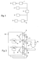
- FIG. 1 shows a block diagram of a pair of plus and minus end stages according to the invention.
- a control 2 is connected to a plus output stage 1.
- the plus output stage 1 is connected via its other output with a squib 3 and a diagnosis 4.
- the squib 3 is connected to a diagnosis 5 and a minus output stage 6.
- the minus output stage 6 is in turn driven by a control 7.
- the ignition circuit is thus formed by the plus output stage 1, the squib 3 and the negative output stage 6.
- the squib or the ignition circuit 3 is supplied by the plus and minus power stage, which are turned on in a tripping case to supply the ignition circuit with the ignition.
- the plus output stage is so named because the supply voltage is connected to it while the minus output stage is connected to ground.
- the own Control for the plus and minus power amplifiers 1 and 6 ensures that the plus and minus power stages of one pair can be cross coupled to other plus and minus power stages of other pairs to power a squib.
- the plus and minus power amplifiers of a couple have a common power supply here. Alternatively, separate power supplies are possible.
- FIG. 2 shows a block diagram of the device according to the invention.
- a pair of plus and minus output stages are arranged in a block 12, schematically other couples 13 and 14 are shown below.
- the plus output stage is formed by a plus-end transistor 8, which is connected via a terminal 10 to a squib 18, which is connected at its other output to the terminal 15, which belongs to a minus output stage, which is arranged in another pair. This is the pair 13.
- the terminal 10 is further connected to a diagnosis 4 associated with the plus-end transistor 8.
- a negative terminal transistor 9 of the pair 12 is here connected to no squib, but it is possible to connect it to such a squib which is connected to another plus-stage transistor of another pair to achieve the cross-coupling.
- the minus end stage transistor 9 has its own diagnosis 5.
- Another squib 17 is connected via a terminal 11 to a plus-stage transistor of the pair 13.
- the squib 17 is connected to a terminal 16 of the pair 14 so as to be connected to the minus output stage of the pair 14 here.
- the terminals 11, 15 and 16 respectively associated with the positive and the minus-stage transistors associated diagnostic blocks.
- the base or the gate of the transistors 8 and 9 and the transistors of the pairs 13 and 14 covered here are driven by a processor in order to switch through these transistors accordingly.
- Transistors 8 and 9, as well as the blinds, are turned on to ignite the squibs 17 and 18 if retaining means are to be triggered.
- the diagnoses 4 and 5 and the hidden diagnoses of the pairs 13 and 14 carry out diagnostic measurements of the squibs 17 and 18.
- the squibs 17 and 18 are measured for too large or too small resistances.
- the resistors are measured via voltages that drop due to diagnostic currents on the squibs 17 and 18.
- the drives 2 and 7 are driver circuits that are driven by the processor in the case of triggering.
- the drive circuits 2 and 7 are thus connected to the gate and the base of the transistors 8 and 9, respectively.
Landscapes
- Engineering & Computer Science (AREA)
- Mechanical Engineering (AREA)
- General Engineering & Computer Science (AREA)
- Air Bags (AREA)
- Ignition Installations For Internal Combustion Engines (AREA)
Description
- Die Erfindung geht aus von einer Vorrichtung zur Ansteuerung von Zündkreisen nach der Gattung des unabhängigen Patentanspruchs.
- Aus der gattungsbildenden Deutschen Patentschrift anmeldung DE 101 09 620.8 C ist eine Vorrichtung zur Ansteuerung von Zündkreisen bekannt, bei der für einen Zündkreis eine Plus- und Minus-Endstufe von jeweils unterschiedlichen Substraten verwendet werden.
- Die erfindungsgemäße Vorrichtung zur Ansteuerung von Zündkreisen mit den Merkmalen des unabhängigen Patentanspruchs hat demgegenüber den Vorteil, dass die Vorrichtung kostengünstiger ist, da nun die kreuzgekoppelten Plus- und Minus-Endstufen auf einem einzigen Substrat angeordnet sind. Auch die Modularität der Anordnung wird dabei wesentlich erhöht. Gegenüber Lösungen ohne eine erfindungsgemäße Kreuzkopplung ergibt sich ein signifikanter Sicherheitsgewinn, weil die Plus- und Minusendstufen mit ihrer zugehörigen Zündkreisdiagnose und Ansteuerung unabhängig voneinander ausgeführt sind.
- Durch die in den abhängigen Ansprüchen aufgeführten Maßnahmen und Weiterbildungen sind vorteilhafte Verbesserungen der im unabhängigen Patentanspruch angegebenen Vorrichtung zur Ansteuerung von Zündkreisen möglich.
- Besonders vorteilhaft ist, dass der geometrische Abstand zwischen der Plus- und Minus-Endstufe des gleichen Zündkreises auf dem Substrat maximiert wird. Dies erhöht die Sicherheit, da durch einen möglichst großen Abstand zwischen der Plus- und Minus-Endstufe für den gleichen Zündkreis so eine große Unabhängigkeit von Fertigungstoleranzen, die auf einem Teil des Substrats lokalisiert sein können, erreicht wird.
- Weiterhin ist es von Vorteil, dass ein Paar aus Plus- und Minus-Endstufe die gleiche Energieversorgung aufweisen kann. Dies führt zu einem erheblichen schaltungstechnischen Vorteil und vereinfacht das Design.
- Ein Ausführungsbeispiel der Erfindung ist in der Zeichnung dargestellt und in der nachfolgenden Beschreibung näher erläutert.
- Es zeigen
- Figur 1
- ein Blockschaltbild eines erfindungsgemäßen Paares aus Plus- und Minus-Endstufe und
- Figur 2
- ein Blockschaltbild der erfindungsgemäßen Vorrichtung.
- Figur 1 zeigt ein Blockschaltbild eines erfindungsgemäßen Paares aus Plus- und Minus-Endstufe. Eine Ansteuerung 2 ist mit einer Plusendstufe 1 verbunden. Die Plusendstufe 1 ist über ihren anderen Ausgang mit einer Zündpille 3 verbunden und einer Diagnose 4. Auf der anderen Seite ist die Zündpille 3 mit einer Diagnose 5 und einer Minusendstufe 6 verbunden. Die Minusendstufe 6 wird wiederum von einer Ansteuerung 7 angesteuert.
- Der Zündkreis wird also von der Plusendstufe 1, der Zündpille 3 und der Minusendstufe 6 gebildet. Dazu kommen noch die Diagnosen 4 und 5 sowie die Ansteuerungen 2 und 7. Die Zündpille bzw. der Zündkreis 3 wird von der Plus- und Minus-Endstufe versorgt, die bei einem Auslösefall durchgeschaltet werden, um den Zündkreis mit dem Zündstrom zu versorgen. Die Plusendstufe wird so genannt, da an ihr die Versorgungsspannung angeschlossen ist, während die Minusendstufe an Masse angeschlossen ist. Die eigene Ansteuerung für die Plus- und Minus-Endstufe 1 und 6 sorgt dafür, dass die Plus- und Minus-Endstufe eines Paares mit anderen Plus- und Minus-Endstufen anderer Paare kreuzgekoppelt werden können, um eine Zündpille zu versorgen. Die Plus- und Minus-Endstufe eines Paares haben hier eine gemeinsame Energieversorgung. Es sind alternativ auch getrennte Energieversorgungen möglich.
- Figur 2 zeigt in einem Blockschaltbild die erfindungsgemäße Vorrichtung. Ein Paar aus Plus- und Minus-Endstufe ist in einem Block 12 angeordnet, schematisch sind darunter andere Paare 13 und 14 dargestellt. Die Plusendstufe wird durch einen Plusendstufentransistor 8 gebildet, der über einen Anschluss 10 mit einer Zündpille 18 verbunden ist, die an ihrem anderen Ausgang mit dem Anschluss 15 verbunden ist, der zu einer Minusendstufe gehört, die in einem anderen Paar angeordnet ist. Dies ist das Paar 13. An den Anschluss 10 ist weiterhin eine Diagnose 4 angeschlossen, die zu dem Plusendstufentransistor 8 gehört. Ein Minusendstufentransistor 9 des Paares 12 ist hier mit keiner Zündpille verbunden, es ist jedoch möglich, ihn mit einer solchen Zündpille zu verbinden, die mit einem anderen Plusendstufentransistor eines anderen Paares verbunden ist, um die Kreuzkopplung zu erreichen. An seinem Anschluss weist der Minusendstufentransistor 9 eine eigene Diagnose 5 auf. Eine weitere Zündpille 17 ist über einen Anschluss 11 mit einem Plusendstufentransistor des Paares 13 verbunden. Auf ihrer anderen Seite ist die Zündpille 17 an einen Anschluss 16 des Paares 14 angeschlossen, um hier mit der Minusendstufe des Paares 14 verbunden zu sein. An den Anschlüssen 11, 15 und 16 sind jeweils den Plus- bzw. den Minus-Endstufentransistoren zugeordnete Diagnoseblöcke zugeordnet.
- Die Basis oder das Gate der Transistoren 8 und 9 und der hier verdeckten Transistoren der Paare 13 und 14 wird von einem Prozessor angesteuert, um diese Transistoren entsprechend durchzuschalten. Die Transistoren 8 und 9 sowie die Verdeckten werden durchgeschaltet, um die Zündpillen 17 und 18 zu zünden, falls Rückhaltemittel ausgelöst werden sollen. Im Normalfall, also wenn die Zündpillen 17 und 18 nicht gezündet werden sollen, führen die Diagnosen 4 und 5 sowie die verdeckten Diagnosen der Paare 13 und 14 Diagnosemessungen der Zündpillen 17 und 18 durch. Dabei werden die Zündpillen 17 und 18 auf zu große bzw. zu kleine Widerstände vermessen. Die Widerstände werden über Spannungen vermessen, die auf Grund von Diagnoseströmen an den Zündpillen 17 und 18 abfallen. Überschreiten die Spannungen an den Zündpillen 17 und 18 vorgegebene Werte, dann liegt ein Fehlverhalten der Zündpillen 17 und 18 vor und die Funktionsweise der Zündpillen 17 und 18 ist gefährdet, und damit auch der Einsatz der Rückhaltemittel. Dies führt dann gegebenenfalls zu einer Warnung bzw. ein Abschalten der Rückhaltemittel.
- Die Ansteuerungen 2 und 7 sind Treiberschaltungen, die von dem Prozessor im Auslösefall angesteuert werden. Die Ansteuerschaltungen 2 und 7 sind demnach mit dem Gate bzw. der Basis der Transistoren 8 und 9 verbunden.
Claims (2)
- Vorrichtung zur Ansteuerung von Zündkreisen, wobei die Vorrichtung für jeden Zündkreis (17, 18) jeweils eine Plus- und Minus-Endstufe (1, 6, 8, 9) aufweist, wobei jeder Plusendstufe (1, 8) und jeder Minusendstufe (6, 9) jeweils eine Ansteuerung (2, 7) und eine Diagnose (4, 5) zugeordnet sind, dadurch gekennzeichnet, dass die Plus- und Minus-Endstufen (1, 6, 8, 9) auf einem einzigen Substrat in Paaren (12, 13, 14) hergestellt sind und dass für jeden Zündkreis (17, 18) eine Plus- und eine Minus-Endstufe aus unterschiedlichen Paaren (12, bis 14) vorgesehen sind.
- Vorrichtung nach Anspruch 1, dadurch gekennzeichnet, dass die Plus- und Minus-Endstufe (1, 6, 8, 9) des gleichen Paares (12 bis 14) jeweils mit der gleichen Energieversorgung verbunden sind.
Applications Claiming Priority (3)
| Application Number | Priority Date | Filing Date | Title |
|---|---|---|---|
| DE10232359A DE10232359A1 (de) | 2002-07-17 | 2002-07-17 | Vorrichtung zur Ansteuerung von Zündkreisen |
| DE10232359 | 2002-07-17 | ||
| PCT/DE2003/000587 WO2004016475A1 (de) | 2002-07-17 | 2003-02-25 | Vorrichtung zur ansteuerung von zündkreisen |
Publications (2)
| Publication Number | Publication Date |
|---|---|
| EP1525119A1 EP1525119A1 (de) | 2005-04-27 |
| EP1525119B1 true EP1525119B1 (de) | 2006-06-14 |
Family
ID=30010111
Family Applications (1)
| Application Number | Title | Priority Date | Filing Date |
|---|---|---|---|
| EP03709649A Expired - Lifetime EP1525119B1 (de) | 2002-07-17 | 2003-02-25 | Vorrichtung zur ansteuerung von zündkreisen |
Country Status (4)
| Country | Link |
|---|---|
| US (1) | US7095234B2 (de) |
| EP (1) | EP1525119B1 (de) |
| DE (2) | DE10232359A1 (de) |
| WO (1) | WO2004016475A1 (de) |
Families Citing this family (1)
| Publication number | Priority date | Publication date | Assignee | Title |
|---|---|---|---|---|
| DE10344841B4 (de) * | 2003-09-26 | 2010-02-25 | Infineon Technologies Ag | Ansteuerschaltung für ein Zündelement eines Insassenschutzsystems |
Family Cites Families (3)
| Publication number | Priority date | Publication date | Assignee | Title |
|---|---|---|---|---|
| US5410253A (en) * | 1993-04-08 | 1995-04-25 | Delco Electronics Corporation | Method of indicating combustion in an internal combustion engine |
| US6597181B2 (en) | 2000-10-31 | 2003-07-22 | Autoliv Asp, Inc. | High and low side driver tests for airbag module |
| DE10109620C1 (de) * | 2001-02-28 | 2002-06-13 | Bosch Gmbh Robert | Vorrichtung zur Ansteuerung von Zündkreisen |
-
2002
- 2002-07-17 DE DE10232359A patent/DE10232359A1/de not_active Withdrawn
-
2003
- 2003-02-25 DE DE50303854T patent/DE50303854D1/de not_active Expired - Lifetime
- 2003-02-25 WO PCT/DE2003/000587 patent/WO2004016475A1/de not_active Ceased
- 2003-02-25 EP EP03709649A patent/EP1525119B1/de not_active Expired - Lifetime
- 2003-02-25 US US10/520,560 patent/US7095234B2/en not_active Expired - Lifetime
Also Published As
| Publication number | Publication date |
|---|---|
| EP1525119A1 (de) | 2005-04-27 |
| WO2004016475A1 (de) | 2004-02-26 |
| DE10232359A1 (de) | 2004-02-05 |
| DE50303854D1 (de) | 2006-07-27 |
| US20060055412A1 (en) | 2006-03-16 |
| US7095234B2 (en) | 2006-08-22 |
Similar Documents
| Publication | Publication Date | Title |
|---|---|---|
| DE102007012462B4 (de) | Vorrichtung zur Ansteuerung von Personenschutzmitteln | |
| DE102009009875B4 (de) | Einrichtung zur Erfassung von Fehlfunktionen elektromagnetischer Bremsen von Robotern | |
| DE4429331A1 (de) | Steuervorrichtung für reversiblen Motor und motorangetriebenes Servolenkungssystem für Motorfahrzeug unter Benutzung derselben | |
| DE10102994A1 (de) | Vorrichtung zur Daten- und/oder Energieübertragung zu Rückhaltemitteln in einem Fahrzeug | |
| DE19505334A1 (de) | Elektronisches Gerät | |
| EP2217475B1 (de) | Vorrichtung zum elektrischen betätigen eines sicherheitskritischen systems | |
| DE102004041869A1 (de) | Elektronische Lenkungsverriegelung | |
| EP1720737B1 (de) | Vorrichtung zur bestromung wenigstens einer zündendstufe mittels eines zündstroms aus einer energiereserve | |
| EP1525119B1 (de) | Vorrichtung zur ansteuerung von zündkreisen | |
| DE10109620C1 (de) | Vorrichtung zur Ansteuerung von Zündkreisen | |
| DE102005009069A1 (de) | Steuerschaltung einer Leistungs-Halbleiter-Vorrichtung und steuernde integrierte Schaltung | |
| WO2011120484A1 (de) | Kraftfahrzeugtürverschluss | |
| EP2115847B1 (de) | Kraftfahrzeug-steuergerät mit verpolschutz | |
| EP1973014B1 (de) | Einrichtung und Verfahren zur automatischen Erkennung und Unterscheidung von an eine zweikanalige Sicherheitskombination angeschlossenen ein- oder zweikanaligen elektronischen Sensoren | |
| EP0141166A2 (de) | Schaltanordnung für Elektrowerkzeuge | |
| DE102021211075A1 (de) | Antriebsanordnung und Fahrzeug mit einer solchen Antriebsanordnung | |
| EP1865565B1 (de) | System zum Betreiben eines piezoelektrischen Elements | |
| DE102005028491B4 (de) | Elektronischer Steuerschalter für eine Kraftfahrzeug-Antriebsstrang-Anwendung und elektronisches Steuersystem | |
| DE10031467C2 (de) | Schaltungsanordnung zur Ansteuerung eines elektrischen Schaltelements | |
| DE4234261C5 (de) | Türverriegelungseinrichtung für Kraftfahrzeuge | |
| DE19843074A1 (de) | Zündstromkreis für Auslösemittel passiver Insassenschutzeinrichtungen | |
| DE10312009B3 (de) | Halbleiterschalter mit Temperatursensoren, insb. geeignet für Fahrzeuge | |
| DE3628343C2 (de) | ||
| DE4313298B4 (de) | Schaltungsanordnung | |
| DE102009029682B4 (de) | ELV-Baugruppe zur Ankopplung an ein Steuergerät |
Legal Events
| Date | Code | Title | Description |
|---|---|---|---|
| PUAI | Public reference made under article 153(3) epc to a published international application that has entered the european phase |
Free format text: ORIGINAL CODE: 0009012 |
|
| 17P | Request for examination filed |
Effective date: 20050217 |
|
| AK | Designated contracting states |
Kind code of ref document: A1 Designated state(s): AT BE BG CH CY CZ DE DK EE ES FI FR GB GR HU IE IT LI LU MC NL PT SE SI SK TR |
|
| 17Q | First examination report despatched |
Effective date: 20050630 |
|
| RBV | Designated contracting states (corrected) |
Designated state(s): DE FR GB |
|
| GRAP | Despatch of communication of intention to grant a patent |
Free format text: ORIGINAL CODE: EPIDOSNIGR1 |
|
| GRAS | Grant fee paid |
Free format text: ORIGINAL CODE: EPIDOSNIGR3 |
|
| GRAA | (expected) grant |
Free format text: ORIGINAL CODE: 0009210 |
|
| AK | Designated contracting states |
Kind code of ref document: B1 Designated state(s): DE FR GB |
|
| REG | Reference to a national code |
Ref country code: GB Ref legal event code: FG4D Free format text: NOT ENGLISH |
|
| REF | Corresponds to: |
Ref document number: 50303854 Country of ref document: DE Date of ref document: 20060727 Kind code of ref document: P |
|
| GBT | Gb: translation of ep patent filed (gb section 77(6)(a)/1977) |
Effective date: 20060924 |
|
| ET | Fr: translation filed | ||
| PLBE | No opposition filed within time limit |
Free format text: ORIGINAL CODE: 0009261 |
|
| STAA | Information on the status of an ep patent application or granted ep patent |
Free format text: STATUS: NO OPPOSITION FILED WITHIN TIME LIMIT |
|
| 26N | No opposition filed |
Effective date: 20070315 |
|
| REG | Reference to a national code |
Ref country code: FR Ref legal event code: PLFP Year of fee payment: 14 |
|
| REG | Reference to a national code |
Ref country code: FR Ref legal event code: PLFP Year of fee payment: 15 |
|
| REG | Reference to a national code |
Ref country code: FR Ref legal event code: PLFP Year of fee payment: 16 |
|
| PGFP | Annual fee paid to national office [announced via postgrant information from national office to epo] |
Ref country code: GB Payment date: 20210222 Year of fee payment: 19 |
|
| PGFP | Annual fee paid to national office [announced via postgrant information from national office to epo] |
Ref country code: FR Payment date: 20220221 Year of fee payment: 20 |
|
| PGFP | Annual fee paid to national office [announced via postgrant information from national office to epo] |
Ref country code: DE Payment date: 20220426 Year of fee payment: 20 |
|
| GBPC | Gb: european patent ceased through non-payment of renewal fee |
Effective date: 20220225 |
|
| PG25 | Lapsed in a contracting state [announced via postgrant information from national office to epo] |
Ref country code: GB Free format text: LAPSE BECAUSE OF NON-PAYMENT OF DUE FEES Effective date: 20220225 |
|
| REG | Reference to a national code |
Ref country code: DE Ref legal event code: R071 Ref document number: 50303854 Country of ref document: DE |