EP1525114B1 - Locking device for a vehicle seat - Google Patents
Locking device for a vehicle seat Download PDFInfo
- Publication number
- EP1525114B1 EP1525114B1 EP03766220A EP03766220A EP1525114B1 EP 1525114 B1 EP1525114 B1 EP 1525114B1 EP 03766220 A EP03766220 A EP 03766220A EP 03766220 A EP03766220 A EP 03766220A EP 1525114 B1 EP1525114 B1 EP 1525114B1
- Authority
- EP
- European Patent Office
- Prior art keywords
- locking device
- locking element
- vehicle seat
- clamping eccentric
- stop
- Prior art date
- Legal status (The legal status is an assumption and is not a legal conclusion. Google has not performed a legal analysis and makes no representation as to the accuracy of the status listed.)
- Expired - Lifetime
Links
Images

Classifications
-
- B—PERFORMING OPERATIONS; TRANSPORTING
- B60—VEHICLES IN GENERAL
- B60N—SEATS SPECIALLY ADAPTED FOR VEHICLES; VEHICLE PASSENGER ACCOMMODATION NOT OTHERWISE PROVIDED FOR
- B60N2/00—Seats specially adapted for vehicles; Arrangement or mounting of seats in vehicles
- B60N2/24—Seats specially adapted for vehicles; Arrangement or mounting of seats in vehicles for particular purposes or particular vehicles
- B60N2/42—Seats specially adapted for vehicles; Arrangement or mounting of seats in vehicles for particular purposes or particular vehicles the seat constructed to protect the occupant from the effect of abnormal g-forces, e.g. crash or safety seats
- B60N2/433—Safety locks for back-rests, e.g. with locking bars activated by inertia
-
- B—PERFORMING OPERATIONS; TRANSPORTING
- B60—VEHICLES IN GENERAL
- B60N—SEATS SPECIALLY ADAPTED FOR VEHICLES; VEHICLE PASSENGER ACCOMMODATION NOT OTHERWISE PROVIDED FOR
- B60N2/00—Seats specially adapted for vehicles; Arrangement or mounting of seats in vehicles
- B60N2/02—Seats specially adapted for vehicles; Arrangement or mounting of seats in vehicles the seat or part thereof being movable, e.g. adjustable
- B60N2/22—Seats specially adapted for vehicles; Arrangement or mounting of seats in vehicles the seat or part thereof being movable, e.g. adjustable the back-rest being adjustable
- B60N2/235—Seats specially adapted for vehicles; Arrangement or mounting of seats in vehicles the seat or part thereof being movable, e.g. adjustable the back-rest being adjustable by gear-pawl type mechanisms
- B60N2/2352—Seats specially adapted for vehicles; Arrangement or mounting of seats in vehicles the seat or part thereof being movable, e.g. adjustable the back-rest being adjustable by gear-pawl type mechanisms with external pawls
Definitions
- the invention relates to a locking device for a vehicle seat, in particular for a motor vehicle seat, with the features of the preamble of claim 1 and a fitting, which has such a locking device, and a vehicle seat with at least one such fitting.
- Known locking device of this type locks a fitting for Lehnenne Trentseingnagna.
- the catching piece is normally arranged in the opening direction of the locking element at a distance to this, while it bears in the radial direction of the locking element at this.
- unlocking takes the catch piece after a certain pivoting the coupled clamping eccentric.
- the catching piece supports the pawl, while the tensioning eccentric can escape.
- a reaction of the clamping eccentric could take place on the catch piece.
- the invention is based on the object to improve a locking device of the type mentioned. This object is achieved by a locking device with the features of claim 1. Advantageous embodiments are the subject of the dependent claims.
- the locking device according to the invention can be used even at very high, pulse-like loads, for example, be used in a designed as Lehnenne Trentseinsteller fitting or a locking device for vehicle structural connection of the vehicle seat.
- the coupling between the catching piece and the clamping eccentric via a slot-pin guide or similar path-delaying means has the advantage that space can be saved.
- the stopper is preferably provided on a control cam, with which the clamping eccentric cooperates and which is connected to the locking element, since then - according to their function - different thickness components can be arranged space-saving in different levels.
- the stop is preferably formed on the control cam, so that it - cost-neutral - can be punched out of a metal sheet simultaneously with this.
- the catching piece In order to avoid any momentum transfer to the catching piece before contact of the locking element on the catching piece, the catching piece normally lies against a fixed stop which is preferably attached to a component which is connected to the various bearings for the pivotable components of the locking device, for example attached to a fitting part.
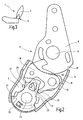
- a vehicle seat 1 of a motor vehicle is provided for adjusting the inclination of its back 3 on both sides with a fitting 5.
- the fitting 5 has a seat part structure fixed fitting lower part 7 and a lean structure-fixed fitting upper part 8, which is pivotally mounted on a backrest bearing pin 9 relative to the lower fitting part 7.
- the lower fitting part 7 consists of two plate-shaped, parallel housing parts which provide a space between them for receiving a locking device 11 described in more detail below.
- a pawl 15 is pivotally mounted as a locking element.
- To lock the pawl 15 cooperates by means of a toothing with a ring gear 18 as a counter element, which is integrally formed on the upper fitting part 8.
- a likewise mounted on the pawl bearing pin 13 control cam 19 is rotatably connected to the pawl 15. The control cam 19 controls in cooperation with controls of the upper fitting part 8, the engagement of the pawl 15 in the ring gear 18th
- a clamping eccentric 21 is pivotally mounted on an eccentric bearing pin 23 and loaded by a spring not shown in the closing direction.
- the clamping eccentric 21 provided with an eccentrically curved clamping surface with respect to the eccentric bearing pin 23 acts on the control cam 19, which presses the pawl 15 into the ring gear 18.
- a catch piece 25 is pivotally mounted on the eccentric bearing pin 23, which spring-loaded against a fixedly connected to the lower fitting part 7 stop pin 27 is pressed.
- the catching piece 25 is normally arranged at a small distance from the pawl I S on the side facing away from the ring gear 18 side. This distance is less than the tooth height of the teeth of the pawl 15 and the ring gear 18. In the event of a crash, the catching piece 25 supports the pawl 15 loaded with an opening moment, so that the latter can not open.
- the catching piece 25 is provided with an unlocking bolt 29 which projects on the one hand through a gate of the fitting lower part 7 to the outside and engages on the other side through a window 31 of the clamping eccentric.
- the clamping eccentric 21 and the catching piece 25 are coupled together via a slot-pin guide 33.
- a pulse is given to the clamping eccentric 21. Since the clamping eccentric 21 bears against the control cam 19 outside the self-locking, the clamping eccentric 21 is greatly accelerated by the impulse in the opening direction. In order to avoid that the clamping eccentric 21 transmits the pulse to the catching piece 25 via its couplings, in particular before the latter can support the pawl 15, a stop 35 is provided on the control cam 19. The stopper 35 is finger-shaped and the control cam 19 on the upper part of the fitting 8 side facing away formed in the region of the pawl bearing pin 13. The clamping eccentric 21 comes into contact with the stop 35 before the edge of the window 31 touches the unlocking pin 29. The catching piece 25 thus remains at rest and can support the pawl 15.
Abstract
Description
Die Erfindung betrifft eine Verriegelungsvorrichtung für einen Fahrzeugsitz, insbesondere für einen Kraftfahrzeugsitz, mit den Merkmalen des Oberbegriffs des Anspruches 1 sowie einen Beschlag, der eine solche Verriegelungsvorrichtung aufweist, und einen Fahrzeugsitz mit wenigstens einem solchen Beschlag.The invention relates to a locking device for a vehicle seat, in particular for a motor vehicle seat, with the features of the preamble of
Eine aus der
Der Erfindung liegt die Aufgabe zu Grunde, eine Verriegelungsvorrichtung der eingangs genannten Art zu verbessern. Diese Aufgabe wird erfindungsgemäß durch eine Verriegelungsvorrichtung mit den Merkmalen des Anspruches 1 gelöst. Vorteilhafte Ausgestaltungen sind Gegenstand der Unteransprüche.The invention is based on the object to improve a locking device of the type mentioned. This object is achieved by a locking device with the features of
Dadurch, dass ein dem Verriegelungselement zugeordneter Anschlag zum Zusammenwirken mit dem Spannexzenter im Crashfall vorgesehen ist, wobei im Falle des Zusammenwirkens des Spannexzenters und des Anschlags der Spannexzenter in Anlage an den Anschlag gelangt, bevor die Kopplung mit dem Fangstück wirksam wird, kann eine Ausweichbewegung des Spannexzenters im Crashfall gestoppt werden. Eine Rückwirkung auf das Fangstück, welche bei hohen Belastungsspitzen auftreten könnte, wobei das Fangstück durch eine Bewegung seine gewünschte Position verlassen könnte, kann ausgeschlossen werden. Damit kann die erfindungsgemäße Verriegelungsvorrichtung auch bei sehr hohen, impulsartigen Belastungen eingesetzt werden, beispielsweise in einem als Lehnenneigungseinsteller ausgebildeten Beschlag oder einer Schließvorrichtung zur Fahrzeugstrukturanbindung des Fahrzeugsitzes eingesetzt werden. Die Kopplung zwischen dem Fangstück und dem Spannexzenter über eine Schlitz-Zapfen-Führung oder ähnliche wegverzögernde Mittel hat den Vorteil, daß Bauraum eingespart werden kann.Due to the fact that a stop associated with the locking element is intended to cooperate with the clamping eccentric in the event of a crash, in which case the clamping eccentric comes into contact with the stop in the event of interaction between the clamping eccentric and the stop before the coupling with the catching piece becomes effective Spanxzenters be stopped in the event of a crash. A reaction to the catch piece, which could occur at high load peaks, wherein The catch piece could leave its desired position by a movement can be excluded. Thus, the locking device according to the invention can be used even at very high, pulse-like loads, for example, be used in a designed as Lehnenneigungseinsteller fitting or a locking device for vehicle structural connection of the vehicle seat. The coupling between the catching piece and the clamping eccentric via a slot-pin guide or similar path-delaying means has the advantage that space can be saved.
Der Anschlag ist vorzugsweise an einem Steuernocken vorgesehen, mit welchem der Spannexzenter zusammenwirkt und der mit dem Verriegelungselement verbunden ist, da dann - entsprechend ihrer Funktion - verschieden dicke Bauteile in verschiedenen Ebenen bauraumsparend angeordnet werden können. Zur einfacheren Herstellung ist der Anschlag vorzugsweise am Steuernocken angeformt, so daß er - kostenneutral - gleichzeitig mit diesem aus einem Blech ausgestanzt werden kann.The stopper is preferably provided on a control cam, with which the clamping eccentric cooperates and which is connected to the locking element, since then - according to their function - different thickness components can be arranged space-saving in different levels. For ease of manufacture, the stop is preferably formed on the control cam, so that it - cost-neutral - can be punched out of a metal sheet simultaneously with this.
Um jeglichen Impulsübertrag auf das Fangstück vor Anlage des Verriegelungselementes am Fangstück zu vermeiden, liegt das Fangstück im Normalfall an einem festen Anschlag an, der vorzugsweise an einem Bauteil, welches mit den diversen Lagern für die schwenkbaren Bauteile der Verriegelungsvorrichtung verbunden ist, angebracht ist, beispielsweise an einem Beschlagteil angebracht ist.In order to avoid any momentum transfer to the catching piece before contact of the locking element on the catching piece, the catching piece normally lies against a fixed stop which is preferably attached to a component which is connected to the various bearings for the pivotable components of the locking device, for example attached to a fitting part.
Im folgenden ist die Erfindung anhand eines in der Zeichnung dargestellten Ausführungsbeispiels näher erläutert. Es zeigen
- Fig. 1
- eine Ansicht des Ausführungsbeispiels im verriegelten Zustand im Normal- fall,
- Fig. 2
- eine Ansicht entsprechend
Fig. 1 nach einem hohen Impuls, und - Fig. 3
- eine schematische Darstellung eines Fahrzeugsitzes.
- Fig. 1
- a view of the embodiment in the locked state in the normal case,
- Fig. 2
- a view accordingly
Fig. 1 after a high pulse, and - Fig. 3
- a schematic representation of a vehicle seat.
Ein Fahrzeugsitz 1 eines Kraftfahrzeuges ist zur Neigungseinstellung seiner Lehne 3 auf beiden Seiten mit einem Beschlag 5 versehen. Der Beschlag 5 weist ein sitzteilstrukturfestes Beschlagunterteil 7 und ein lehnenstrukturfestes Beschlagoberteil 8 auf, welches auf einem Lehnenlagerbolzen 9 relativ zum Beschlagunterteil 7 schwenkbar gelagert ist. Das Beschlagunterteil 7 besteht aus zwei plattenförmigen, parallelen Gehäuseteilen, welche zwischen sich einen Bauraum zur Aufnahme einer nachfolgend genauer beschriebenen Verriegelungsvorrichtung 11 zur Verfügung stellen.A
Auf einem Klinkenlagerbolzen 13 des Beschlagunterteils 7 ist eine Sperrklinke 15 als Verriegelungselement schwenkbar gelagert. Zum Verriegeln wirkt die Sperrklinke 15 mittels einer Verzahnung mit einem Zahnkranz 18 als Gegenelement zusammen, welcher am Beschlagoberteil 8 angeformt ist. Ein ebenfalls auf dem Klinkenlagerbolzen 13 gelagerter Steuernocken 19 ist mit der Sperrklinke 15 drehfest verbunden. Der Steuernocken 19 steuert in Zusammenwirken mit Steuerelementen des Beschlagoberteils 8 das Einfallen der Sperrklinke 15 in den Zahnkranz 18.On a pawl bearing
Um den verriegelten Zustand der beschriebenen Elemente der Verriegelungsvorrichtung 11 zu sichern, sind verschiedene Sicherungselemente vorgesehen. Ein Spannexzenter 21 ist schwenkbar auf einem Exzenterlagerbolzen 23 gelagert und durch eine nicht näher dargestellte Feder in Schließrichtung belastet. Der mit einer bezüglich des Exzenterlagerbolzens 23 exzentrisch gekrümmten Spannfläche versehene Spannexzenter 21 wirkt auf den Steuernocken 19 ein, welcher die Sperrklinke 15 in den Zahnkranz 18 drückt. In der Ebene der Sperrklinke 15 ist auf dem Exzenterlagerbolzen 23 ein Fangstück 25 schwenkbar gelagert, welches federbelastet gegen einen fest mit dem Beschlagunterteil 7 verbundenen Anschlagsbolzen 27 gedrückt wird.In order to secure the locked state of the described elements of the
Im beschriebenen verriegelten Zustand der Verriegelungsvorrichtung 11 ist das Fangstück 25 im Normalfall in einem geringen Abstand zur Sperrklinke I S auf deren vom Zahnkranz 18 abgewandten Seite angeordnet. Dieser Abstand ist geringer als die Zahnhöhe der Verzahnung der Sperrklinke 15 und des Zahnkranzes 18. Im Crashfall stützt das Fangstück 25 die mit einem öffnenden Moment belastete Sperrklinke 15 ab, so daß letztere nicht öffnen kann.In the described locked state of the
Zum Entriegeln der Verriegelungsvorrichtung 11 ist das Fangstück 25 mit einem Entriegelungsbolzen 29 versehen, welcher auf der einen Seite durch eine Kulisse des Beschlagunterteils 7 nach außen ragt und auf der anderen Seite durch ein Fenster 31 des Spannexzenters greift. Außer dieser Kopplung über den Entriegelungsbolzen 29 und das Fenster 31 sind der Spannexzenter 21 und das Fangstück 25 über eine Schlitz-Zapfen-Führung 33 miteinander gekoppelt. Beim Entriegeln wird zunächst das Fangstück 25 über den Entriegelungsbolzen 29 von der Sperrklinke 15 weggeschwenkt, wobei nach Erreichen des Randes des Fensters 31 durch den Entriegelungsbolzen 29 der Spannexzenter 21 wegverzögert mitgenommen wird und dieser den Steuernocken 19 und damit die Sperrklinke 15 freigibt.To unlock the
Im Crashfall kann es sein, daß über die Lehne 3, das Beschlagoberteil 8, die Sperrklinke 15 und der Steuernocken 19 ein Impuls auf den Spannexzenter 21 gegeben wird. Da der Spannexzenter 21 außerhalb der Selbsthemmung am Steuernocken 19 anliegt, wird der Spannexzenter 21 durch den Impuls in Öffnungsrichtung stark beschleunigt. Um zu vermeiden, daß der Spannexzenter 21 über seine Kopplungen den Impuls auf das Fangstück 25 überträgt, insbesondere bevor letzteres die Sperrklinke 15 abstützen kann, ist am Steuernocken 19 ein Anschlag 35 vorgesehen. Der Anschlag 35 ist fingerförmig ausgebildet und am Steuernocken 19 auf der vom Beschlagoberteil 8 abgewandten Seite im Bereich des Klinkenlagerbolzens 13 angeformt. Der Spannexzenter 21 gelangt in Anlage an den Anschlag 35, bevor der Rand des Fensters 31 den Entriegelungsbolzen 29 berührt. Das Fangstück 25 bleibt somit in Ruhe und kann die Sperrklinke 15 abstützen.In the event of a crash, it may be that on the
- 11
- Fahrzeugsitzvehicle seat
- 33
- Lehnerest
- 55
- Beschlagfitting
- 77
- BeschlagunterteilFitting part
- 88th
- BeschlagoberteilUpper member
- 99
- LehnenlagerbolzenSit bearing bolt
- 1111
- Verriegelungsvorrichtunglocking device
- 1313
- KlinkenlagerbolzenPawl bearing bolt
- 1515
- Sperrklinke, VerriegelungselementPawl, locking element
- 1818
- Zahnkranz, GegenelementSprocket, counter element
- 1919
- Steuernockencontrol cam
- 2121
- Spannexzenterclamping eccentric
- 2323
- ExzenterlagerbolzenExzenterlagerbolzen
- 2525
- Fangstückcatching piece
- 2727
- Anschlagsbolzenstop pin
- 2929
- Entriegelungsbolzenunlocking
- 3131
- Fensterwindow
- 3333
- Schlitz-Zapfen-FührungSlot-pin guide
- 3535
- Anschlagattack
Claims (9)
- Locking device for a vehicle seat, in particular for a motor vehicle seat, with a pivotably mounted locking element (15), with which a stop (35) is associated, a mating element (18) which interacts with the locking element (15), a pivotably mounted, spring-loaded clamping eccentric (21) which acts on the locking element (15) and normally holds this in engagement with the mating element (18), and an intercepting piece (25) which is coupled to the clamping eccentric (21) and supports the locking element (15) in the event of a crash, characterised in that the stop (35) associated with the locking element (15) is provided for interaction with the clamping eccentric (21) in the event of a crash in that, when it is significantly accelerated by an impulse in the opening direction in the event of a crash, the clamping eccentric (21) comes to bear against the stop (35) before the coupling with the intercepting piece (25) becomes effective.
- Locking device according to Claim 1, characterised in that the clamping eccentric (21) and the intercepting piece (25) are coupled for entrainment with a travel delay.
- Locking device according to Claim 1 or 2, characterised in that the clamping eccentric (21) acts on the locking element (15) via a control cam (19) which is connected in a rotationally rigid manner to the locking element (15).
- Locking device according to Claim 3, characterised in that the stop (35) is formed on the control cam (19).
- Locking device according to Claim 4, characterised in that the stop (35) is integrally formed on the control cam (19) in the form of a finger.
- Locking device according to any one of Claims 1 to 5, characterised in that the locking element (15), the clamping eccentric (21) and the intercepting piece (25) are mounted on a common component (7).
- Locking device according to Claim 6, characterised in that the common component (7) has a fixed stop (27) against which the intercepting piece (25) normally bears.
- Fitting, in particular adjuster (5) for adjusting the inclination of a component (3) of a vehicle seat (1) or for connecting the vehicle seat (1) to a vehicle structure, characterised by a locking device according to any one of Claims 1 to 7.
- Vehicle seat (1) with at least one fitting (5) according to Claim 8.
Applications Claiming Priority (3)
| Application Number | Priority Date | Filing Date | Title |
|---|---|---|---|
| DE10235141 | 2002-08-01 | ||
| DE10235141A DE10235141B4 (en) | 2002-08-01 | 2002-08-01 | Locking device for a vehicle seat |
| PCT/EP2003/007836 WO2004012959A1 (en) | 2002-08-01 | 2003-07-18 | Locking device for a vehicle seat |
Publications (2)
| Publication Number | Publication Date |
|---|---|
| EP1525114A1 EP1525114A1 (en) | 2005-04-27 |
| EP1525114B1 true EP1525114B1 (en) | 2009-03-11 |
Family
ID=30128610
Family Applications (1)
| Application Number | Title | Priority Date | Filing Date |
|---|---|---|---|
| EP03766220A Expired - Lifetime EP1525114B1 (en) | 2002-08-01 | 2003-07-18 | Locking device for a vehicle seat |
Country Status (6)
| Country | Link |
|---|---|
| US (1) | US6893093B2 (en) |
| EP (1) | EP1525114B1 (en) |
| JP (1) | JP4282075B2 (en) |
| BR (1) | BR0305711B1 (en) |
| DE (2) | DE10235141B4 (en) |
| WO (1) | WO2004012959A1 (en) |
Families Citing this family (18)
| Publication number | Priority date | Publication date | Assignee | Title |
|---|---|---|---|---|
| DE10304574B4 (en) * | 2003-02-05 | 2005-02-03 | Keiper Gmbh & Co. Kg | Locking device for a vehicle seat |
| FR2857305B1 (en) * | 2003-07-10 | 2005-10-07 | Faurecia Sieges Automobile | ARTICULATED BACKHOE VEHICLE SEAT COMPRISING MEANS FOR BLOCKING THE BACKREST IN THE EVENT OF A FRONTAL SHOCK |
| DE102004011138B4 (en) * | 2004-03-08 | 2006-03-16 | Keiper Gmbh & Co.Kg | Height and longitudinal adjusting mechanism for vehicle seat, comprising parts engaging in case of impact |
| DE102004011785B3 (en) * | 2004-03-09 | 2005-08-11 | Keiper Gmbh & Co. Kg | Fitting for vehicle seat has second part exerting closing torque on pawl plate on returning from out-of-use position to use position |
| DE102004041449B3 (en) | 2004-08-27 | 2006-03-09 | Keiper Gmbh & Co.Kg | Fitting for a vehicle seat, in particular for a motor vehicle seat |
| FR2876560B1 (en) * | 2004-10-19 | 2007-01-12 | Antolin Grupo Ing Sa | ARTICULATION DEVICE FOR A SEAT |
| DE102005033068B3 (en) * | 2005-07-15 | 2007-01-04 | Keiper Gmbh & Co.Kg | Mechanism for adjusting position of backrest of car seat, comprises specific arrangement of components in extreme positions in order to avoid jamming |
| DE102005060218A1 (en) * | 2005-10-11 | 2007-04-19 | Keiper Gmbh & Co.Kg | Vehicle seating, particularly motor vehicle seat, has backrest rotating around axis, and inclination of seat is adjusted by lockable fitting or backrest drive unit |
| DE102005057623B3 (en) | 2005-12-02 | 2007-05-10 | Keiper Gmbh & Co.Kg | Motor vehicle seat, has fitting comprising locking unit and counter unit that work together with locking unit, and control device determining relative position of locking and counter units to check suitable orientation for locking fitting |
| DE102006018755B3 (en) * | 2006-04-22 | 2007-10-04 | Keiper Gmbh & Co.Kg | Bearing arrangement for a vehicle seat comprises a bearing region arranged on a first bearing element or on a first component and an eccentric element rotating on a second bearing element or second component |
| DE102006038765B4 (en) * | 2006-08-17 | 2015-02-26 | Faurecia Autositze Gmbh | vehicle seat |
| DE102006058891B4 (en) * | 2006-12-04 | 2009-04-09 | Progress-Werk Oberkirch Ag | Device for locking a vehicle seat |
| FR2913638B1 (en) * | 2007-03-13 | 2009-06-12 | Faurecia Sieges Automobile | SEAT TILT ADJUSTMENT MECHANISM AND SEAT EQUIPPED WITH SUCH A MECHANISM |
| US7775598B2 (en) * | 2007-07-03 | 2010-08-17 | Keiper Gmbh & Co. Kg | Fitting for a vehicle seat |
| US7871127B2 (en) * | 2008-08-01 | 2011-01-18 | Bae Industries, Inc. | Seat recliner/dump mechanism such as incorporated into a seatback slaved to a floor latch release |
| JP5439492B2 (en) * | 2008-10-23 | 2014-03-12 | ジョンソン・コントロールズ・ゲー・エム・ベー・ハー | Locking device, in particular for adjusting devices and in particular for vehicle seats, and vehicle seat |
| JP6809161B2 (en) * | 2016-11-21 | 2021-01-06 | トヨタ紡織株式会社 | Vehicle seat |
| US11833930B2 (en) * | 2021-05-11 | 2023-12-05 | Textron Innovations Inc. | Seat backrest inertial locking system |
Family Cites Families (10)
| Publication number | Priority date | Publication date | Assignee | Title |
|---|---|---|---|---|
| US5154476A (en) * | 1991-02-21 | 1992-10-13 | Hoover Universal, Inc. | Locking seat recliner |
| US5540117A (en) * | 1993-12-17 | 1996-07-30 | Keiper Recaro Gmbh & Co. | Locking system for articulated fittings of car seats, in particular for wobble fittings |
| US6209955B1 (en) * | 1998-10-21 | 2001-04-03 | Johnson Controls Technology Company | Vehicle seat with a yielding recliner stop |
| US6139105A (en) * | 1999-04-06 | 2000-10-31 | Dura Automotive Systems, Inc. | Easy entry latch for seat recliner |
| DE10018125B4 (en) * | 2000-04-12 | 2010-10-07 | Keiper Gmbh & Co. Kg | Articulated fitting for a vehicle seat |
| DE10035258B4 (en) * | 2000-07-20 | 2004-06-03 | Keiper Gmbh & Co. Kg | Locking device for a vehicle seat |
| DE10124618B4 (en) * | 2001-05-21 | 2005-03-24 | Keiper Gmbh & Co. Kg | Lock fitting for a vehicle seat |
| DE10135627B4 (en) * | 2001-07-20 | 2004-10-14 | Keiper Gmbh & Co. Kg | Locking device for a vehicle seat |
| DE10135433C1 (en) * | 2001-07-20 | 2002-10-31 | Keiper Gmbh & Co | Backrest adjustment system for vehicle seat has pawl engaging on wheel on hinge axis and interacting with safety lever on lower part of seat frame |
| DE10148375A1 (en) * | 2001-09-29 | 2003-04-24 | Keiper Gmbh & Co | Fitting for a vehicle seat |
-
2002
- 2002-08-01 DE DE10235141A patent/DE10235141B4/en not_active Expired - Lifetime
-
2003
- 2003-07-18 WO PCT/EP2003/007836 patent/WO2004012959A1/en active Application Filing
- 2003-07-18 EP EP03766220A patent/EP1525114B1/en not_active Expired - Lifetime
- 2003-07-18 BR BRPI0305711-9B1A patent/BR0305711B1/en not_active IP Right Cessation
- 2003-07-18 DE DE50311283T patent/DE50311283D1/en not_active Expired - Lifetime
- 2003-07-18 JP JP2004525245A patent/JP4282075B2/en not_active Expired - Lifetime
-
2004
- 2004-07-14 US US10/890,951 patent/US6893093B2/en not_active Expired - Lifetime
Also Published As
| Publication number | Publication date |
|---|---|
| WO2004012959A1 (en) | 2004-02-12 |
| DE10235141A1 (en) | 2004-02-12 |
| JP2005534385A (en) | 2005-11-17 |
| DE10235141B4 (en) | 2008-08-07 |
| BR0305711A (en) | 2004-09-28 |
| JP4282075B2 (en) | 2009-06-17 |
| DE50311283D1 (en) | 2009-04-23 |
| EP1525114A1 (en) | 2005-04-27 |
| BR0305711B1 (en) | 2013-12-17 |
| US20040245816A1 (en) | 2004-12-09 |
| US6893093B2 (en) | 2005-05-17 |
Similar Documents
| Publication | Publication Date | Title |
|---|---|---|
| EP1525114B1 (en) | Locking device for a vehicle seat | |
| EP1673255B1 (en) | Locking device for a vehicle seat | |
| EP1976723B1 (en) | Fitting for a vehicle seat | |
| EP2310227B1 (en) | Locking mechanism for a vehicle seat | |
| EP2296936B1 (en) | Locking mechanism for a vehicle seat | |
| EP1187738B1 (en) | Hinged fitting for a vehicle seat | |
| DE10132701B4 (en) | Fitting for a vehicle seat | |
| DE19654395C1 (en) | Cam for releasable locking of vehicle seat | |
| EP0158990B1 (en) | Motor car seat | |
| DE102015017354B4 (en) | Longitudinal adjuster for a vehicle seat | |
| EP2057033B1 (en) | Locking device for a vehicle seat | |
| EP1121263B1 (en) | Height adjustment device for a vehicle seat | |
| EP2566719A1 (en) | Fitting for a vehicle seat | |
| DE2800908A1 (en) | SEAT ADJUSTMENT DEVICE FOR VEHICLES | |
| DE10048127A1 (en) | Car seat mounting allowing back rest to recline has pawl pivoted on first part cooperating with teeth on second part to lock components in place, eccentric which holds pawl in locked position pivoting against locking component in crash | |
| EP1260404B1 (en) | Locking device for a vehicle seat | |
| EP1240048B1 (en) | Adjuster for a vehicle seat | |
| EP1431105A2 (en) | Locking device for a vehicle seat | |
| EP1083083B1 (en) | Hinge for a vehicle seat | |
| DE10135627B4 (en) | Locking device for a vehicle seat | |
| EP1728674A2 (en) | Fitting for a vehicle seat | |
| DE10224826B4 (en) | Locking device for a vehicle seat | |
| DE102004011785B3 (en) | Fitting for vehicle seat has second part exerting closing torque on pawl plate on returning from out-of-use position to use position | |
| DE102008030568A1 (en) | Lock, for a motor vehicle swing door/flap, has a support to prevent movement of the locking bolt against the rotting spring bolt when in the locked position | |
| EP3254891B1 (en) | Backrest structure |
Legal Events
| Date | Code | Title | Description |
|---|---|---|---|
| PUAI | Public reference made under article 153(3) epc to a published international application that has entered the european phase |
Free format text: ORIGINAL CODE: 0009012 |
|
| 17P | Request for examination filed |
Effective date: 20040304 |
|
| AK | Designated contracting states |
Kind code of ref document: A1 Designated state(s): DE FR GB IT |
|
| 17Q | First examination report despatched |
Effective date: 20080526 |
|
| GRAP | Despatch of communication of intention to grant a patent |
Free format text: ORIGINAL CODE: EPIDOSNIGR1 |
|
| GRAS | Grant fee paid |
Free format text: ORIGINAL CODE: EPIDOSNIGR3 |
|
| GRAA | (expected) grant |
Free format text: ORIGINAL CODE: 0009210 |
|
| AK | Designated contracting states |
Kind code of ref document: B1 Designated state(s): DE FR GB IT |
|
| REG | Reference to a national code |
Ref country code: GB Ref legal event code: FG4D Free format text: NOT ENGLISH |
|
| REF | Corresponds to: |
Ref document number: 50311283 Country of ref document: DE Date of ref document: 20090423 Kind code of ref document: P |
|
| PLBE | No opposition filed within time limit |
Free format text: ORIGINAL CODE: 0009261 |
|
| STAA | Information on the status of an ep patent application or granted ep patent |
Free format text: STATUS: NO OPPOSITION FILED WITHIN TIME LIMIT |
|
| 26N | No opposition filed |
Effective date: 20091214 |
|
| PG25 | Lapsed in a contracting state [announced via postgrant information from national office to epo] |
Ref country code: IT Free format text: LAPSE BECAUSE OF FAILURE TO SUBMIT A TRANSLATION OF THE DESCRIPTION OR TO PAY THE FEE WITHIN THE PRESCRIBED TIME-LIMIT Effective date: 20090311 |
|
| REG | Reference to a national code |
Ref country code: DE Ref legal event code: R082 Ref document number: 50311283 Country of ref document: DE |
|
| REG | Reference to a national code |
Ref country code: DE Ref legal event code: R081 Ref document number: 50311283 Country of ref document: DE Owner name: JOHNSON CONTROLS COMPONENTS GMBH & CO. KG, DE Free format text: FORMER OWNER: KEIPER GMBH & CO. KG, 67657 KAISERSLAUTERN, DE Effective date: 20140710 Ref country code: DE Ref legal event code: R081 Ref document number: 50311283 Country of ref document: DE Owner name: ADIENT LUXEMBOURG HOLDING S.A.R.L., LU Free format text: FORMER OWNER: KEIPER GMBH & CO. KG, 67657 KAISERSLAUTERN, DE Effective date: 20140710 Ref country code: DE Ref legal event code: R081 Ref document number: 50311283 Country of ref document: DE Owner name: ADIENT LUXEMBOURG HOLDING S.A R.L., LU Free format text: FORMER OWNER: KEIPER GMBH & CO. KG, 67657 KAISERSLAUTERN, DE Effective date: 20140710 |
|
| PGFP | Annual fee paid to national office [announced via postgrant information from national office to epo] |
Ref country code: GB Payment date: 20140721 Year of fee payment: 12 |
|
| GBPC | Gb: european patent ceased through non-payment of renewal fee |
Effective date: 20150718 |
|
| PG25 | Lapsed in a contracting state [announced via postgrant information from national office to epo] |
Ref country code: GB Free format text: LAPSE BECAUSE OF NON-PAYMENT OF DUE FEES Effective date: 20150718 |
|
| REG | Reference to a national code |
Ref country code: FR Ref legal event code: PLFP Year of fee payment: 14 |
|
| REG | Reference to a national code |
Ref country code: DE Ref legal event code: R081 Ref document number: 50311283 Country of ref document: DE Owner name: ADIENT US LLC, PLYMOUTH, US Free format text: FORMER OWNER: JOHNSON CONTROLS COMPONENTS GMBH & CO. KG, 67657 KAISERSLAUTERN, DE Ref country code: DE Ref legal event code: R081 Ref document number: 50311283 Country of ref document: DE Owner name: ADIENT LUXEMBOURG HOLDING S.A.R.L., LU Free format text: FORMER OWNER: JOHNSON CONTROLS COMPONENTS GMBH & CO. KG, 67657 KAISERSLAUTERN, DE Ref country code: DE Ref legal event code: R081 Ref document number: 50311283 Country of ref document: DE Owner name: ADIENT LUXEMBOURG HOLDING S.A R.L., LU Free format text: FORMER OWNER: JOHNSON CONTROLS COMPONENTS GMBH & CO. KG, 67657 KAISERSLAUTERN, DE |
|
| REG | Reference to a national code |
Ref country code: FR Ref legal event code: PLFP Year of fee payment: 15 |
|
| REG | Reference to a national code |
Ref country code: DE Ref legal event code: R081 Ref document number: 50311283 Country of ref document: DE Owner name: ADIENT US LLC, PLYMOUTH, US Free format text: FORMER OWNER: ADIENT LUXEMBOURG HOLDING S.A.R.L., LUXEMBOURG, LU Ref country code: DE Ref legal event code: R081 Ref document number: 50311283 Country of ref document: DE Owner name: ADIENT LUXEMBOURG HOLDING S.A R.L., LU Free format text: FORMER OWNER: ADIENT LUXEMBOURG HOLDING S.A.R.L., LUXEMBOURG, LU |
|
| REG | Reference to a national code |
Ref country code: FR Ref legal event code: PLFP Year of fee payment: 16 |
|
| REG | Reference to a national code |
Ref country code: DE Ref legal event code: R082 Ref document number: 50311283 Country of ref document: DE Representative=s name: LIEDHEGENER, RALF, DIPL.-ING., DE |
|
| REG | Reference to a national code |
Ref country code: DE Ref legal event code: R081 Ref document number: 50311283 Country of ref document: DE Owner name: ADIENT US LLC, PLYMOUTH, US Free format text: FORMER OWNER: ADIENT LUXEMBOURG HOLDING S.A R.L., LUXEMBOURG, LU |
|
| PGFP | Annual fee paid to national office [announced via postgrant information from national office to epo] |
Ref country code: DE Payment date: 20220727 Year of fee payment: 20 |
|
| PGFP | Annual fee paid to national office [announced via postgrant information from national office to epo] |
Ref country code: FR Payment date: 20220725 Year of fee payment: 20 |
|
| REG | Reference to a national code |
Ref country code: DE Ref legal event code: R071 Ref document number: 50311283 Country of ref document: DE |