JP4282075B2 - Lock device for vehicle seat - Google Patents
Lock device for vehicle seat Download PDFInfo
- Publication number
- JP4282075B2 JP4282075B2 JP2004525245A JP2004525245A JP4282075B2 JP 4282075 B2 JP4282075 B2 JP 4282075B2 JP 2004525245 A JP2004525245 A JP 2004525245A JP 2004525245 A JP2004525245 A JP 2004525245A JP 4282075 B2 JP4282075 B2 JP 4282075B2
- Authority
- JP
- Japan
- Prior art keywords
- vehicle seat
- locking device
- clamp eccentric
- lock
- stopper
- Prior art date
- Legal status (The legal status is an assumption and is not a legal conclusion. Google has not performed a legal analysis and makes no representation as to the accuracy of the status listed.)
- Expired - Lifetime
Links
Images


Classifications
-
- B—PERFORMING OPERATIONS; TRANSPORTING
- B60—VEHICLES IN GENERAL
- B60N—SEATS SPECIALLY ADAPTED FOR VEHICLES; VEHICLE PASSENGER ACCOMMODATION NOT OTHERWISE PROVIDED FOR
- B60N2/00—Seats specially adapted for vehicles; Arrangement or mounting of seats in vehicles
- B60N2/24—Seats specially adapted for vehicles; Arrangement or mounting of seats in vehicles for particular purposes or particular vehicles
- B60N2/42—Seats specially adapted for vehicles; Arrangement or mounting of seats in vehicles for particular purposes or particular vehicles the seat constructed to protect the occupant from the effect of abnormal g-forces, e.g. crash or safety seats
- B60N2/433—Safety locks for back-rests, e.g. with locking bars activated by inertia
-
- B—PERFORMING OPERATIONS; TRANSPORTING
- B60—VEHICLES IN GENERAL
- B60N—SEATS SPECIALLY ADAPTED FOR VEHICLES; VEHICLE PASSENGER ACCOMMODATION NOT OTHERWISE PROVIDED FOR
- B60N2/00—Seats specially adapted for vehicles; Arrangement or mounting of seats in vehicles
- B60N2/02—Seats specially adapted for vehicles; Arrangement or mounting of seats in vehicles the seat or part thereof being movable, e.g. adjustable
- B60N2/22—Seats specially adapted for vehicles; Arrangement or mounting of seats in vehicles the seat or part thereof being movable, e.g. adjustable the back-rest being adjustable
- B60N2/235—Seats specially adapted for vehicles; Arrangement or mounting of seats in vehicles the seat or part thereof being movable, e.g. adjustable the back-rest being adjustable by gear-pawl type mechanisms
- B60N2/2352—Seats specially adapted for vehicles; Arrangement or mounting of seats in vehicles the seat or part thereof being movable, e.g. adjustable the back-rest being adjustable by gear-pawl type mechanisms with external pawls
Description
【0001】
【技術分野】
本発明は、回動可能に取り付けられたロック部材と、このロック部材と噛み合って相互作用する相手部材と、該相手部材がロック部材にロックされた通常状況でロック部材を相手部材に係合させて保持するように回動可能に取り付けられてばね付勢されたクランプ偏心部材と、該クランプ偏心部材を開放方向に急加速する衝撃がクランプ偏心部材に加わる衝突状況で支持するようにクランプ偏心部材に連結された遮断部材とを有する車両座席用ロック装置、特に自動車座席用ロック装置に関する。
【背景技術】
【0002】
このような従来の車両座席用ロック装置は、背もたれの傾斜を設定するためにフィッティングをロックするようになっている。
そして、通常状況では、遮断部材がロック部材の開放方向にロック部材から一定距離を置いて配置されている一方、その半径方向でロック部材に当接している。
したがって、従来の車両座席用ロック装置の解除プロセスでは、遮断部材が一定の回動経路の後、この遮断部材に連結されているクランプ偏心部材を一緒に搬送する。
そして、衝突状況では、遮断部材は、クランプ偏心部材がわきへ移動する間、ロック部材を支持するようになっている。スロット及びピンガイドによる連結の場合、クランプ偏心部材が遮断部材に反力を加える可能性があった。
【発明の開示】
【発明が解決しようとする課題】
【0003】
本発明は、冒頭に述べた形式の車両座席用ロック装置を改良するという目的に基づいている。
【課題を解決するための手段】
【0004】
本発明の目的は、クランプ偏心部材を開放方向に急加速する衝撃がクランプ偏心部材に加わる衝突状況で、前記ロック部材に一体化して連結されたストッパが、前記クランプ偏心部材に当接することで前記クランプ偏心部材から遮断部材への衝撃の伝達を回避して前記遮断部材によりロック部材を支持する静止状態を維持するように設けられている車両座席用ロック装置によって達成される。
【0005】
すなわち、本発明の車両座席用ロック装置では、ロック部材に対応付けられたストッパが、衝突状況においてクランプ偏心部材と相互作用するように設けられていることから、衝突状況でのクランプ偏心部材の降伏移動を停止させることができる。遮断部材に加えられる反力は、高負荷ピークで発生し、遮断部材が移動して所望位置を離れるであろうが、それを排除することができる。
したがって、本発明の車両座席用ロック装置は、非常に高い衝撃負荷の場合にも使用でき、たとえば、背もたれの傾斜を設定する手段として構成されたフィッティングに使用したり、車両座席を車両構造体に連結するために使用したりすることができる。
しかも、スロット及びピンガイド、または、同様な移動遅れ手段を介した遮断部材とクランプ偏心部材との間の連結には、構造的空間を節約できるという利点がある。
【0006】
また、前述したストッパは、クランプ偏心部材と相互作用すると共にロック部材に連結されている制御カムに設けられるのが好ましく、その場合には、それぞれの機能に応じて異なった厚さを有する部材を異なった平面上に配置でき、構造的空間が節約される。
さらに、簡単に製造するために、このストッパは、制御カムに一体状に形成されるのが好ましく、これによって、ストッパを制御カムと共に金属板から同時に打ち抜くことができ、コストの点で中程度の効果がある。
【0007】
通常状況において、ロック部材が遮断部材に当接する前に遮断部材に衝撃が伝達されることを避けるために、遮断部材は、固定ストッパに当接しており、この固定ストッパは、車両座席用ロック装置の回動可能な種々の支持部に連結されている部材に固定されているのが好ましい、たとえば、フィッティング部材に固定されている。
【発明を実施するための最良の形態】
【0008】
次に、図面に示されている本発明の実施例を参照しながら、さらに詳細に説明する。
【0009】
図3に示すような自動車用座席などの車両座席1は、その背もたれ3の傾斜を設定するために、フィッティング5を両側に備えている。
そして、このようなフィッティング5は、図1及び図2に示すように、座部構造体に固定されたフィッティング下部7と、背もたれ構造体に固定されてフィッティング下部7に対して回動可能に背もたれ支持ボルト9に取り付けられたフィッティング上部8とを有する。
さらに、前記フィッティング下部7は、2つのプレート状の平行ハウジング部材を有し、これらの間に構造空間が設けられて、以下のような車両座席用ロック装置11を収容している。
【0010】
すなわち、ロック部材として回転止め爪(detent pawl)15が、共通部材となるフィッティング下部7の爪支持ボルト13に回動可能に取り付けられている。そして、この回転止め爪15が、ロックのために、フィッティング上部8に一体形成された相手部材である歯付きリム18と噛み合って相互作用する。
同様に、爪支持ボルト13に取り付けられた制御カム19が、回転止め爪15と一体化して回転可能に連結されている。そして、この制御カム19が、フィッティング上部8の制御部材(具体的に図示せず)と相互作用して、歯付きリム18内への回転止め爪15の食い込みを制御する。
【0011】
そして、本実施例の車両座席用ロック装置11には、回転止め爪15と歯付きリム18とのロック状態を確実に保持するために、さまざまな固定部材が設けられている。
すなわち、クランプ偏心部材21が、偏心部材支持ボルト23に回動可能に取り付けられて、ばね(具体的に図示せず)によって閉鎖方向に付勢されている。
そして、偏心部材支持ボルト23と偏心した状態で湾曲しているクランプ表面を備えたクランプ偏心部材21が、回転止め爪15を歯付きリム18内へ押し込むように制御カム19に作用する。
また、この回転止め爪15の平面上で偏心部材支持ボルト23に回動可能に取り付けられた遮断部材25が、フィッティング下部7に固定連結されているストップボルト27にばね付勢状態で押し付けられている。
【0012】
そこで、本実施例の車両座席用ロック装置11のロック状態では、前述した遮断部材25は、通常状況で、歯付きリム18に面する側と反対側が回転止め爪15とわずかな間隔をおいて配置されている。この間隔は、回転止め爪15と歯付きリム18との噛み合い部分の歯の高さより小さい。
そして、衝突状況では、遮断部材25が、開放モーメントを加えられる回転止め爪15を支持する結果、回転止め爪15が開放できないようになっている。
【0013】
さらに、本実施例では、車両座席用ロック装置11を解除するために、前述した遮断部材25に解除ボルト29が設けられており、この解除ボルト29の一方側が、フィッティング下部7のスロット形ガイドを通って外部へ突出し、その他方側が、クランプ偏心部材の開口31を通って伸びている。そして、このような解除ボルト29と開口31との連結から離れた位置で、クランプ偏心部材21と遮断部材25とが、スロット及びピンガイド33によって互いに連結されている。
したがって、車両座席用ロック装置11の解除プロセスでは、まず、前述した遮断部材25が解除ボルト29を介して回転止め爪15から離れる方向に回動して、解除ボルト29が開口31の縁部に到達した後、クランプ偏心部材21が移動遅れを伴って移動すると、制御カム19を介して回転止め爪15を歯付きリム18から解放するようになっている。
【0014】
つぎに、衝突状況では、クランプ偏心部材21が、背もたれ3、フィッティング上部8、回転止め爪15及び制御カム19を介して衝撃を受ける。このとき、クランプ偏心部材21は、図1に示すように自己ロック以外で制御カム19に当接しているので、このクランプ偏心部材21は、図2に示すように、衝撃によって開放方向に急加速されるようになっている。
特に、前述した遮断部材25が回転止め爪15を支持する前に、クランプ偏心部材21が衝撃力をその連結部を介して遮断部材25に伝達するのを避けるために、制御カム19にストッパ35が設けられている。
そして、このストッパ35は、指形に構成されて、制御カム19のフィッティング上部8に面する側と反対側で爪支持ボルト13付近に一体状に形成されている。クランプ偏心部材21は、開口31の縁部が解除ボルト29に接する前に、図2に示すように、ストッパ35に当接する。
したがって、遮断部材25は、静止したままであって、回転止め爪15を支持することができる。
【図面の簡単な説明】
【0015】
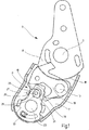
【図1】 本実施例である車両座席用ロック装置11の通常状況におけるロック状態図。
【図2】 本実施例である車両座席用ロック装置11の衝撃状況における作動図。
【図3】 本実施例である車両座席用ロック装置11を用いた車両座席の概略図。
【符号の説明】
1 ・・・車両座席
3 ・・・背もたれ
5 ・・・フィッティング
7 ・・・共通部材(フィッティング下部)
8 ・・・フィッティング上部
9 ・・・背もたれ支持ボルト
11 ・・・車両座席用ロック装置
13 ・・・爪支持ボルト
15 ・・・ロック部材(回転止め爪)
18 ・・・相手部材(歯付きリム)
19 ・・・制御カム
21 ・・・クランプ偏心部材
23 ・・・偏心部材支持ボルト
25 ・・・遮断部材
27 ・・・ストップボルト
29 ・・・解除ボルト
31 ・・・開口
33 ・・・スロット及びピンガイド
35 ・・・ストッパ[0001]
【Technical field】
The present invention relates to a lock member that is pivotally attached, a mating member that engages and interacts with the lock member, and engages the lock member with the mating member in a normal situation where the mating member is locked to the lock member. A clamp eccentric member that is rotatably mounted so as to be held and is spring-biased, and a clamp eccentric member that supports the clamp eccentric member in a collision situation in which an impact that suddenly accelerates the clamp eccentric member is applied to the clamp eccentric member More particularly, the present invention relates to a vehicle seat locking device having a blocking member connected to the vehicle seat, and more particularly to a vehicle seat locking device.
[Background]
[0002]
Such a conventional vehicle seat locking device locks the fitting to set the inclination of the backrest.
In a normal situation, the blocking member is disposed at a certain distance from the lock member in the opening direction of the lock member, and is in contact with the lock member in the radial direction.
Therefore, in the conventional unlocking process of the vehicle seat locking device, the blocking member conveys together the clamp eccentric member connected to the blocking member after a certain rotation path.
In the collision situation, the blocking member supports the lock member while the clamp eccentric member moves to the side. In the case of the connection by the slot and the pin guide, there is a possibility that the clamp eccentric member applies a reaction force to the blocking member.
DISCLOSURE OF THE INVENTION
[Problems to be solved by the invention]
[0003]
The invention is based on the object of improving a vehicle seat locking device of the type mentioned at the outset.
[Means for Solving the Problems]
[0004]
An object of the present invention is that a stopper integrated and connected to the lock member is brought into contact with the clamp eccentric member in a collision situation where an impact that suddenly accelerates the clamp eccentric member in the opening direction is applied to the clamp eccentric member. This is achieved by a vehicle seat locking device that is provided so as to avoid transmission of an impact from the clamp eccentric member to the blocking member and maintain a stationary state in which the locking member is supported by the blocking member.
[0005]
That is, in the vehicle seat locking device of the present invention, since the stopper associated with the lock member is provided so as to interact with the clamp eccentric member in the collision situation, the yield of the clamp eccentric member in the collision situation The movement can be stopped. The reaction force applied to the blocking member occurs at a high load peak and the blocking member will move away from the desired position, but it can be eliminated.
Therefore, the vehicle seat locking device of the present invention can be used even in the case of a very high impact load. For example, the vehicle seat locking device can be used for fitting configured as a means for setting the inclination of the backrest, or the vehicle seat can be used as a vehicle structure. Or can be used to connect.
Moreover, the connection between the blocking member and the clamp eccentric member via the slot and pin guide or similar movement delay means has the advantage that structural space can be saved.
[0006]
The stopper described above is preferably provided on a control cam that interacts with the clamp eccentric member and is connected to the lock member. In this case, a member having a different thickness is used depending on the function. It can be placed on different planes, saving structural space.
Furthermore, for easy manufacture, this stopper is preferably formed integrally with the control cam, so that the stopper can be punched out of the metal plate together with the control cam, which is moderate in terms of cost. effective.
[0007]
In a normal situation, in order to avoid an impact being transmitted to the blocking member before the locking member contacts the blocking member, the blocking member is in contact with the fixed stopper, and the fixed stopper is a vehicle seat locking device. It is preferable to be fixed to a member connected to various rotatable support portions, for example, to a fitting member.
BEST MODE FOR CARRYING OUT THE INVENTION
[0008]
Next, the present invention will be described in more detail with reference to the embodiments of the present invention shown in the drawings.
[0009]
A vehicle seat 1 such as an automobile seat shown in FIG. 3 has
As shown in FIGS. 1 and 2, the
Furthermore, the fitting
[0010]
That is, a
Similarly, a
[0011]
The vehicle
That is, the clamp
Then, the
Further, the blocking
[0012]
Therefore, in the locked state of the vehicle
In a collision situation, the blocking
[0013]
Further, in this embodiment, in order to release the vehicle
Therefore, in the release process of the vehicle
[0014]
Next, in the collision situation, the clamp
In particular, in order to prevent the clamp
The
Therefore, the blocking
[Brief description of the drawings]
[0015]
FIG. 1 is a lock state diagram in a normal state of a vehicle
FIG. 2 is an operation diagram of the vehicle
FIG. 3 is a schematic view of a vehicle seat using a vehicle
[Explanation of symbols]
DESCRIPTION OF SYMBOLS 1 ... Vehicle seat 3 ...
8 ・ ・ ・ Fitting
18 ... Mating member (toothed rim)
DESCRIPTION OF
Claims (8)
前記クランプ偏心部材(21)を開放方向に急加速する衝撃がクランプ偏心部材(21)に加わる衝突状況で、前記ロック部材(15)に一体化して連結されたストッパ(35)が、前記クランプ偏心部材(21)に当接することで前記クランプ偏心部材(21)から遮断部材(25)への衝撃の伝達を回避して該遮断部材(25)によりロック部材(15)を支持する静止状態を維持するように設けられていることを特徴とする車両座席用ロック装置(11)。A lock member (15) rotatably attached, a mating member (18) that meshes and interacts with the lock member (15), and the mating member (18) is normally locked to the lock member (15) A clamp eccentric member (21) that is pivotally attached and spring-biased so as to engage and hold the locking member (15) in engagement with the mating member (18), and the clamp eccentric member (21). For a vehicle seat having a blocking member (25) connected to the clamp eccentric member (21) so as to support the lock member (15) in a collision situation where an impact suddenly accelerated in the opening direction is applied to the clamp eccentric member (21) A locking device (11),
A stopper (35) integrally connected to the lock member (15) in a collision situation in which an impact that suddenly accelerates the clamp eccentric member (21) in the opening direction is applied to the clamp eccentric member (21). By contacting the member (21), transmission of an impact from the clamp eccentric member (21) to the blocking member (25) is avoided, and a stationary state in which the locking member (15) is supported by the blocking member (25) is maintained. A vehicle seat locking device (11) characterized in that the vehicle seat locking device (11) is provided.
Applications Claiming Priority (2)
| Application Number | Priority Date | Filing Date | Title |
|---|---|---|---|
| DE10235141A DE10235141B4 (en) | 2002-08-01 | 2002-08-01 | Locking device for a vehicle seat |
| PCT/EP2003/007836 WO2004012959A1 (en) | 2002-08-01 | 2003-07-18 | Locking device for a vehicle seat |
Publications (3)
| Publication Number | Publication Date |
|---|---|
| JP2005534385A JP2005534385A (en) | 2005-11-17 |
| JP2005534385A5 JP2005534385A5 (en) | 2006-02-02 |
| JP4282075B2 true JP4282075B2 (en) | 2009-06-17 |
Family
ID=30128610
Family Applications (1)
| Application Number | Title | Priority Date | Filing Date |
|---|---|---|---|
| JP2004525245A Expired - Lifetime JP4282075B2 (en) | 2002-08-01 | 2003-07-18 | Lock device for vehicle seat |
Country Status (6)
| Country | Link |
|---|---|
| US (1) | US6893093B2 (en) |
| EP (1) | EP1525114B1 (en) |
| JP (1) | JP4282075B2 (en) |
| BR (1) | BR0305711B1 (en) |
| DE (2) | DE10235141B4 (en) |
| WO (1) | WO2004012959A1 (en) |
Families Citing this family (18)
| Publication number | Priority date | Publication date | Assignee | Title |
|---|---|---|---|---|
| DE10304574B4 (en) * | 2003-02-05 | 2005-02-03 | Keiper Gmbh & Co. Kg | Locking device for a vehicle seat |
| FR2857305B1 (en) * | 2003-07-10 | 2005-10-07 | Faurecia Sieges Automobile | ARTICULATED BACKHOE VEHICLE SEAT COMPRISING MEANS FOR BLOCKING THE BACKREST IN THE EVENT OF A FRONTAL SHOCK |
| DE102004011138B4 (en) * | 2004-03-08 | 2006-03-16 | Keiper Gmbh & Co.Kg | Height and longitudinal adjusting mechanism for vehicle seat, comprising parts engaging in case of impact |
| DE102004011785B3 (en) * | 2004-03-09 | 2005-08-11 | Keiper Gmbh & Co. Kg | Fitting for vehicle seat has second part exerting closing torque on pawl plate on returning from out-of-use position to use position |
| DE102004041449B3 (en) | 2004-08-27 | 2006-03-09 | Keiper Gmbh & Co.Kg | Fitting for a vehicle seat, in particular for a motor vehicle seat |
| FR2876560B1 (en) * | 2004-10-19 | 2007-01-12 | Antolin Grupo Ing Sa | ARTICULATION DEVICE FOR A SEAT |
| DE102005033068B3 (en) * | 2005-07-15 | 2007-01-04 | Keiper Gmbh & Co.Kg | Mechanism for adjusting position of backrest of car seat, comprises specific arrangement of components in extreme positions in order to avoid jamming |
| DE102005060218A1 (en) * | 2005-10-11 | 2007-04-19 | Keiper Gmbh & Co.Kg | Vehicle seating, particularly motor vehicle seat, has backrest rotating around axis, and inclination of seat is adjusted by lockable fitting or backrest drive unit |
| DE102005057623B3 (en) | 2005-12-02 | 2007-05-10 | Keiper Gmbh & Co.Kg | Motor vehicle seat, has fitting comprising locking unit and counter unit that work together with locking unit, and control device determining relative position of locking and counter units to check suitable orientation for locking fitting |
| DE102006018755B3 (en) * | 2006-04-22 | 2007-10-04 | Keiper Gmbh & Co.Kg | Bearing arrangement for a vehicle seat comprises a bearing region arranged on a first bearing element or on a first component and an eccentric element rotating on a second bearing element or second component |
| DE102006038765B4 (en) * | 2006-08-17 | 2015-02-26 | Faurecia Autositze Gmbh | vehicle seat |
| DE102006058891B4 (en) * | 2006-12-04 | 2009-04-09 | Progress-Werk Oberkirch Ag | Device for locking a vehicle seat |
| FR2913638B1 (en) * | 2007-03-13 | 2009-06-12 | Faurecia Sieges Automobile | SEAT TILT ADJUSTMENT MECHANISM AND SEAT EQUIPPED WITH SUCH A MECHANISM |
| US7775598B2 (en) * | 2007-07-03 | 2010-08-17 | Keiper Gmbh & Co. Kg | Fitting for a vehicle seat |
| US7871127B2 (en) * | 2008-08-01 | 2011-01-18 | Bae Industries, Inc. | Seat recliner/dump mechanism such as incorporated into a seatback slaved to a floor latch release |
| JP5439492B2 (en) * | 2008-10-23 | 2014-03-12 | ジョンソン・コントロールズ・ゲー・エム・ベー・ハー | Locking device, in particular for adjusting devices and in particular for vehicle seats, and vehicle seat |
| JP6809161B2 (en) * | 2016-11-21 | 2021-01-06 | トヨタ紡織株式会社 | Vehicle seat |
| US11833930B2 (en) * | 2021-05-11 | 2023-12-05 | Textron Innovations Inc. | Seat backrest inertial locking system |
Family Cites Families (10)
| Publication number | Priority date | Publication date | Assignee | Title |
|---|---|---|---|---|
| US5154476A (en) * | 1991-02-21 | 1992-10-13 | Hoover Universal, Inc. | Locking seat recliner |
| US5540117A (en) * | 1993-12-17 | 1996-07-30 | Keiper Recaro Gmbh & Co. | Locking system for articulated fittings of car seats, in particular for wobble fittings |
| US6209955B1 (en) * | 1998-10-21 | 2001-04-03 | Johnson Controls Technology Company | Vehicle seat with a yielding recliner stop |
| US6139105A (en) * | 1999-04-06 | 2000-10-31 | Dura Automotive Systems, Inc. | Easy entry latch for seat recliner |
| DE10018125B4 (en) * | 2000-04-12 | 2010-10-07 | Keiper Gmbh & Co. Kg | Articulated fitting for a vehicle seat |
| DE10035258B4 (en) * | 2000-07-20 | 2004-06-03 | Keiper Gmbh & Co. Kg | Locking device for a vehicle seat |
| DE10124618B4 (en) * | 2001-05-21 | 2005-03-24 | Keiper Gmbh & Co. Kg | Lock fitting for a vehicle seat |
| DE10135627B4 (en) * | 2001-07-20 | 2004-10-14 | Keiper Gmbh & Co. Kg | Locking device for a vehicle seat |
| DE10135433C1 (en) * | 2001-07-20 | 2002-10-31 | Keiper Gmbh & Co | Backrest adjustment system for vehicle seat has pawl engaging on wheel on hinge axis and interacting with safety lever on lower part of seat frame |
| DE10148375A1 (en) * | 2001-09-29 | 2003-04-24 | Keiper Gmbh & Co | Fitting for a vehicle seat |
-
2002
- 2002-08-01 DE DE10235141A patent/DE10235141B4/en not_active Expired - Lifetime
-
2003
- 2003-07-18 WO PCT/EP2003/007836 patent/WO2004012959A1/en active Application Filing
- 2003-07-18 EP EP03766220A patent/EP1525114B1/en not_active Expired - Lifetime
- 2003-07-18 BR BRPI0305711-9B1A patent/BR0305711B1/en not_active IP Right Cessation
- 2003-07-18 DE DE50311283T patent/DE50311283D1/en not_active Expired - Lifetime
- 2003-07-18 JP JP2004525245A patent/JP4282075B2/en not_active Expired - Lifetime
-
2004
- 2004-07-14 US US10/890,951 patent/US6893093B2/en not_active Expired - Lifetime
Also Published As
| Publication number | Publication date |
|---|---|
| WO2004012959A1 (en) | 2004-02-12 |
| DE10235141A1 (en) | 2004-02-12 |
| JP2005534385A (en) | 2005-11-17 |
| DE10235141B4 (en) | 2008-08-07 |
| BR0305711A (en) | 2004-09-28 |
| EP1525114B1 (en) | 2009-03-11 |
| DE50311283D1 (en) | 2009-04-23 |
| EP1525114A1 (en) | 2005-04-27 |
| BR0305711B1 (en) | 2013-12-17 |
| US20040245816A1 (en) | 2004-12-09 |
| US6893093B2 (en) | 2005-05-17 |
Similar Documents
| Publication | Publication Date | Title |
|---|---|---|
| JP4282075B2 (en) | Lock device for vehicle seat | |
| JP4480714B2 (en) | Lock mechanism for vehicle seat | |
| US7926858B2 (en) | Lock device | |
| US7762605B2 (en) | Locking device | |
| JP5093223B2 (en) | Locking device | |
| JP3741607B2 (en) | Reclining device | |
| JP2006516502A5 (en) | ||
| US6412849B1 (en) | Chuck-free latch assembly | |
| EP0993391B1 (en) | Removable vehicle seat assembly | |
| US5540117A (en) | Locking system for articulated fittings of car seats, in particular for wobble fittings | |
| JP5865521B2 (en) | Lock unit for vehicle seat | |
| JP5716127B2 (en) | Lock device and vehicle seat | |
| JP2008546594A (en) | Lock / release mechanism with safety device to prevent automatic opening | |
| JP2005029151A (en) | System for locking first element and second element, with seat with this lock system | |
| JPWO2008132973A1 (en) | Locking device | |
| US8882161B2 (en) | Locking device with signal structure | |
| JP4897665B2 (en) | Device and method for locking and / or unlocking components in particular in vehicles | |
| JP4973297B2 (en) | Locking device | |
| JP2003341469A (en) | Shoulder adjuster device | |
| JP2993861B2 (en) | Automotive locking device | |
| US10843589B2 (en) | Locking device for vehicle seat | |
| US9260038B2 (en) | Floor lock for a motor vehicle seat | |
| CN115298407A (en) | Motor vehicle lock | |
| JP6135196B2 (en) | Seat lock device mounting structure | |
| JP2993863B2 (en) | Automotive locking device |
Legal Events
| Date | Code | Title | Description |
|---|---|---|---|
| A521 | Written amendment |
Free format text: JAPANESE INTERMEDIATE CODE: A523 Effective date: 20051129 |
|
| A621 | Written request for application examination |
Free format text: JAPANESE INTERMEDIATE CODE: A621 Effective date: 20051129 |
|
| A131 | Notification of reasons for refusal |
Free format text: JAPANESE INTERMEDIATE CODE: A131 Effective date: 20080805 |
|
| A521 | Written amendment |
Free format text: JAPANESE INTERMEDIATE CODE: A523 Effective date: 20081028 |
|
| A131 | Notification of reasons for refusal |
Free format text: JAPANESE INTERMEDIATE CODE: A131 Effective date: 20090120 |
|
| A521 | Written amendment |
Free format text: JAPANESE INTERMEDIATE CODE: A523 Effective date: 20090223 |
|
| TRDD | Decision of grant or rejection written | ||
| A01 | Written decision to grant a patent or to grant a registration (utility model) |
Free format text: JAPANESE INTERMEDIATE CODE: A01 Effective date: 20090313 |
|
| A01 | Written decision to grant a patent or to grant a registration (utility model) |
Free format text: JAPANESE INTERMEDIATE CODE: A01 |
|
| A61 | First payment of annual fees (during grant procedure) |
Free format text: JAPANESE INTERMEDIATE CODE: A61 Effective date: 20090316 |
|
| R150 | Certificate of patent or registration of utility model |
Ref document number: 4282075 Country of ref document: JP Free format text: JAPANESE INTERMEDIATE CODE: R150 Free format text: JAPANESE INTERMEDIATE CODE: R150 |
|
| FPAY | Renewal fee payment (event date is renewal date of database) |
Free format text: PAYMENT UNTIL: 20120327 Year of fee payment: 3 |
|
| FPAY | Renewal fee payment (event date is renewal date of database) |
Free format text: PAYMENT UNTIL: 20120327 Year of fee payment: 3 |
|
| FPAY | Renewal fee payment (event date is renewal date of database) |
Free format text: PAYMENT UNTIL: 20130327 Year of fee payment: 4 |
|
| R250 | Receipt of annual fees |
Free format text: JAPANESE INTERMEDIATE CODE: R250 |
|
| FPAY | Renewal fee payment (event date is renewal date of database) |
Free format text: PAYMENT UNTIL: 20140327 Year of fee payment: 5 |
|
| R250 | Receipt of annual fees |
Free format text: JAPANESE INTERMEDIATE CODE: R250 |
|
| R250 | Receipt of annual fees |
Free format text: JAPANESE INTERMEDIATE CODE: R250 |
|
| R250 | Receipt of annual fees |
Free format text: JAPANESE INTERMEDIATE CODE: R250 |
|
| R250 | Receipt of annual fees |
Free format text: JAPANESE INTERMEDIATE CODE: R250 |
|
| R250 | Receipt of annual fees |
Free format text: JAPANESE INTERMEDIATE CODE: R250 |
|
| R250 | Receipt of annual fees |
Free format text: JAPANESE INTERMEDIATE CODE: R250 |
|
| R250 | Receipt of annual fees |
Free format text: JAPANESE INTERMEDIATE CODE: R250 |
|
| R250 | Receipt of annual fees |
Free format text: JAPANESE INTERMEDIATE CODE: R250 |
|
| S111 | Request for change of ownership or part of ownership |
Free format text: JAPANESE INTERMEDIATE CODE: R313111 Free format text: JAPANESE INTERMEDIATE CODE: R313113 |
|
| R350 | Written notification of registration of transfer |
Free format text: JAPANESE INTERMEDIATE CODE: R350 |
|
| R360 | Written notification for declining of transfer of rights |
Free format text: JAPANESE INTERMEDIATE CODE: R360 |
|
| R360 | Written notification for declining of transfer of rights |
Free format text: JAPANESE INTERMEDIATE CODE: R360 |
|
| R371 | Transfer withdrawn |
Free format text: JAPANESE INTERMEDIATE CODE: R371 |