EP1525044B1 - Verfahren zur reinigung von luft, vorrichtung zur reinigung von luft und mit dieser vorrichtung versehenes gebäude - Google Patents
Verfahren zur reinigung von luft, vorrichtung zur reinigung von luft und mit dieser vorrichtung versehenes gebäude Download PDFInfo
- Publication number
- EP1525044B1 EP1525044B1 EP03737951A EP03737951A EP1525044B1 EP 1525044 B1 EP1525044 B1 EP 1525044B1 EP 03737951 A EP03737951 A EP 03737951A EP 03737951 A EP03737951 A EP 03737951A EP 1525044 B1 EP1525044 B1 EP 1525044B1
- Authority
- EP
- European Patent Office
- Prior art keywords
- washing liquid
- air
- inlet
- outlet
- acid
- Prior art date
- Legal status (The legal status is an assumption and is not a legal conclusion. Google has not performed a legal analysis and makes no representation as to the accuracy of the status listed.)
- Expired - Lifetime
Links
- 238000000034 method Methods 0.000 title claims abstract description 24
- 239000007788 liquid Substances 0.000 claims abstract description 152
- 238000005406 washing Methods 0.000 claims abstract description 128
- 238000004140 cleaning Methods 0.000 claims abstract description 81
- 239000002253 acid Substances 0.000 claims abstract description 53
- 238000005201 scrubbing Methods 0.000 claims abstract description 30
- 239000000203 mixture Substances 0.000 claims abstract description 23
- 239000013505 freshwater Substances 0.000 claims abstract 5
- QGZKDVFQNNGYKY-UHFFFAOYSA-N Ammonia Chemical compound N QGZKDVFQNNGYKY-UHFFFAOYSA-N 0.000 claims description 50
- 229910021529 ammonia Inorganic materials 0.000 claims description 25
- XLYOFNOQVPJJNP-UHFFFAOYSA-N water Substances O XLYOFNOQVPJJNP-UHFFFAOYSA-N 0.000 claims description 19
- QAOWNCQODCNURD-UHFFFAOYSA-N Sulfuric acid Chemical compound OS(O)(=O)=O QAOWNCQODCNURD-UHFFFAOYSA-N 0.000 claims description 6
- 238000004891 communication Methods 0.000 claims description 5
- 239000001117 sulphuric acid Substances 0.000 claims description 4
- 235000011149 sulphuric acid Nutrition 0.000 claims description 4
- 239000012528 membrane Substances 0.000 claims description 2
- 239000012752 auxiliary agent Substances 0.000 claims 11
- 239000003337 fertilizer Substances 0.000 abstract description 25
- 230000008569 process Effects 0.000 abstract description 7
- 238000004519 manufacturing process Methods 0.000 abstract description 6
- 239000002518 antifoaming agent Substances 0.000 description 12
- 238000005507 spraying Methods 0.000 description 9
- 239000000470 constituent Substances 0.000 description 8
- 238000010276 construction Methods 0.000 description 7
- 238000005265 energy consumption Methods 0.000 description 7
- 239000000126 substance Substances 0.000 description 7
- 239000004743 Polypropylene Substances 0.000 description 5
- -1 polypropylene Polymers 0.000 description 5
- 229920001155 polypropylene Polymers 0.000 description 5
- 238000000746 purification Methods 0.000 description 5
- 239000003153 chemical reaction reagent Substances 0.000 description 4
- 239000000428 dust Substances 0.000 description 4
- 239000012530 fluid Substances 0.000 description 4
- 238000012423 maintenance Methods 0.000 description 4
- 239000000463 material Substances 0.000 description 4
- 238000005192 partition Methods 0.000 description 4
- 238000011282 treatment Methods 0.000 description 4
- 150000007513 acids Chemical class 0.000 description 3
- 239000007795 chemical reaction product Substances 0.000 description 3
- 239000002245 particle Substances 0.000 description 3
- 229920000642 polymer Polymers 0.000 description 3
- 239000000047 product Substances 0.000 description 3
- 238000006243 chemical reaction Methods 0.000 description 2
- 230000000694 effects Effects 0.000 description 2
- 238000005259 measurement Methods 0.000 description 2
- 230000009467 reduction Effects 0.000 description 2
- 239000007787 solid Substances 0.000 description 2
- 239000007921 spray Substances 0.000 description 2
- 241000238631 Hexapoda Species 0.000 description 1
- 241001465754 Metazoa Species 0.000 description 1
- 229910000831 Steel Inorganic materials 0.000 description 1
- 239000004809 Teflon Substances 0.000 description 1
- 229920006362 Teflon® Polymers 0.000 description 1
- 230000009471 action Effects 0.000 description 1
- BFNBIHQBYMNNAN-UHFFFAOYSA-N ammonium sulfate Chemical compound N.N.OS(O)(=O)=O BFNBIHQBYMNNAN-UHFFFAOYSA-N 0.000 description 1
- 229910052921 ammonium sulfate Inorganic materials 0.000 description 1
- 239000001166 ammonium sulphate Substances 0.000 description 1
- 235000011130 ammonium sulphate Nutrition 0.000 description 1
- 230000003190 augmentative effect Effects 0.000 description 1
- 239000006227 byproduct Substances 0.000 description 1
- 239000003795 chemical substances by application Substances 0.000 description 1
- 238000005260 corrosion Methods 0.000 description 1
- 230000007797 corrosion Effects 0.000 description 1
- 230000001419 dependent effect Effects 0.000 description 1
- 238000007599 discharging Methods 0.000 description 1
- 239000004744 fabric Substances 0.000 description 1
- 239000006260 foam Substances 0.000 description 1
- 239000003365 glass fiber Substances 0.000 description 1
- 239000012535 impurity Substances 0.000 description 1
- 230000007246 mechanism Effects 0.000 description 1
- 230000001546 nitrifying effect Effects 0.000 description 1
- 239000003921 oil Substances 0.000 description 1
- 235000019198 oils Nutrition 0.000 description 1
- 238000005457 optimization Methods 0.000 description 1
- 238000012856 packing Methods 0.000 description 1
- 229920000728 polyester Polymers 0.000 description 1
- 229920000915 polyvinyl chloride Polymers 0.000 description 1
- 238000012552 review Methods 0.000 description 1
- 150000003839 salts Chemical class 0.000 description 1
- 238000000926 separation method Methods 0.000 description 1
- 239000010802 sludge Substances 0.000 description 1
- 239000010959 steel Substances 0.000 description 1
- 239000000725 suspension Substances 0.000 description 1
- 238000011144 upstream manufacturing Methods 0.000 description 1
- 235000015112 vegetable and seed oil Nutrition 0.000 description 1
- 239000008158 vegetable oil Substances 0.000 description 1
Images

Classifications
-
- B—PERFORMING OPERATIONS; TRANSPORTING
- B01—PHYSICAL OR CHEMICAL PROCESSES OR APPARATUS IN GENERAL
- B01D—SEPARATION
- B01D53/00—Separation of gases or vapours; Recovering vapours of volatile solvents from gases; Chemical or biological purification of waste gases, e.g. engine exhaust gases, smoke, fumes, flue gases, aerosols
- B01D53/14—Separation of gases or vapours; Recovering vapours of volatile solvents from gases; Chemical or biological purification of waste gases, e.g. engine exhaust gases, smoke, fumes, flue gases, aerosols by absorption
- B01D53/1418—Recovery of products
-
- A—HUMAN NECESSITIES
- A01—AGRICULTURE; FORESTRY; ANIMAL HUSBANDRY; HUNTING; TRAPPING; FISHING
- A01K—ANIMAL HUSBANDRY; AVICULTURE; APICULTURE; PISCICULTURE; FISHING; REARING OR BREEDING ANIMALS, NOT OTHERWISE PROVIDED FOR; NEW BREEDS OF ANIMALS
- A01K1/00—Housing animals; Equipment therefor
- A01K1/0047—Air-conditioning, e.g. ventilation, of animal housings
-
- B—PERFORMING OPERATIONS; TRANSPORTING
- B01—PHYSICAL OR CHEMICAL PROCESSES OR APPARATUS IN GENERAL
- B01D—SEPARATION
- B01D53/00—Separation of gases or vapours; Recovering vapours of volatile solvents from gases; Chemical or biological purification of waste gases, e.g. engine exhaust gases, smoke, fumes, flue gases, aerosols
- B01D53/14—Separation of gases or vapours; Recovering vapours of volatile solvents from gases; Chemical or biological purification of waste gases, e.g. engine exhaust gases, smoke, fumes, flue gases, aerosols by absorption
-
- C—CHEMISTRY; METALLURGY
- C05—FERTILISERS; MANUFACTURE THEREOF
- C05C—NITROGENOUS FERTILISERS
- C05C3/00—Fertilisers containing other salts of ammonia or ammonia itself, e.g. gas liquor
-
- C—CHEMISTRY; METALLURGY
- C05—FERTILISERS; MANUFACTURE THEREOF
- C05F—ORGANIC FERTILISERS NOT COVERED BY SUBCLASSES C05B, C05C, e.g. FERTILISERS FROM WASTE OR REFUSE
- C05F3/00—Fertilisers from human or animal excrements, e.g. manure
- C05F3/06—Apparatus for the manufacture
-
- B—PERFORMING OPERATIONS; TRANSPORTING
- B01—PHYSICAL OR CHEMICAL PROCESSES OR APPARATUS IN GENERAL
- B01D—SEPARATION
- B01D2257/00—Components to be removed
- B01D2257/40—Nitrogen compounds
- B01D2257/406—Ammonia
-
- Y—GENERAL TAGGING OF NEW TECHNOLOGICAL DEVELOPMENTS; GENERAL TAGGING OF CROSS-SECTIONAL TECHNOLOGIES SPANNING OVER SEVERAL SECTIONS OF THE IPC; TECHNICAL SUBJECTS COVERED BY FORMER USPC CROSS-REFERENCE ART COLLECTIONS [XRACs] AND DIGESTS
- Y02—TECHNOLOGIES OR APPLICATIONS FOR MITIGATION OR ADAPTATION AGAINST CLIMATE CHANGE
- Y02A—TECHNOLOGIES FOR ADAPTATION TO CLIMATE CHANGE
- Y02A40/00—Adaptation technologies in agriculture, forestry, livestock or agroalimentary production
- Y02A40/10—Adaptation technologies in agriculture, forestry, livestock or agroalimentary production in agriculture
- Y02A40/20—Fertilizers of biological origin, e.g. guano or fertilizers made from animal corpses
-
- Y—GENERAL TAGGING OF NEW TECHNOLOGICAL DEVELOPMENTS; GENERAL TAGGING OF CROSS-SECTIONAL TECHNOLOGIES SPANNING OVER SEVERAL SECTIONS OF THE IPC; TECHNICAL SUBJECTS COVERED BY FORMER USPC CROSS-REFERENCE ART COLLECTIONS [XRACs] AND DIGESTS
- Y02—TECHNOLOGIES OR APPLICATIONS FOR MITIGATION OR ADAPTATION AGAINST CLIMATE CHANGE
- Y02A—TECHNOLOGIES FOR ADAPTATION TO CLIMATE CHANGE
- Y02A40/00—Adaptation technologies in agriculture, forestry, livestock or agroalimentary production
- Y02A40/70—Adaptation technologies in agriculture, forestry, livestock or agroalimentary production in livestock or poultry
- Y02A40/76—Adaptation technologies in agriculture, forestry, livestock or agroalimentary production in livestock or poultry using renewable energy
-
- Y—GENERAL TAGGING OF NEW TECHNOLOGICAL DEVELOPMENTS; GENERAL TAGGING OF CROSS-SECTIONAL TECHNOLOGIES SPANNING OVER SEVERAL SECTIONS OF THE IPC; TECHNICAL SUBJECTS COVERED BY FORMER USPC CROSS-REFERENCE ART COLLECTIONS [XRACs] AND DIGESTS
- Y02—TECHNOLOGIES OR APPLICATIONS FOR MITIGATION OR ADAPTATION AGAINST CLIMATE CHANGE
- Y02E—REDUCTION OF GREENHOUSE GAS [GHG] EMISSIONS, RELATED TO ENERGY GENERATION, TRANSMISSION OR DISTRIBUTION
- Y02E50/00—Technologies for the production of fuel of non-fossil origin
- Y02E50/30—Fuel from waste, e.g. synthetic alcohol or diesel
-
- Y—GENERAL TAGGING OF NEW TECHNOLOGICAL DEVELOPMENTS; GENERAL TAGGING OF CROSS-SECTIONAL TECHNOLOGIES SPANNING OVER SEVERAL SECTIONS OF THE IPC; TECHNICAL SUBJECTS COVERED BY FORMER USPC CROSS-REFERENCE ART COLLECTIONS [XRACs] AND DIGESTS
- Y02—TECHNOLOGIES OR APPLICATIONS FOR MITIGATION OR ADAPTATION AGAINST CLIMATE CHANGE
- Y02P—CLIMATE CHANGE MITIGATION TECHNOLOGIES IN THE PRODUCTION OR PROCESSING OF GOODS
- Y02P20/00—Technologies relating to chemical industry
- Y02P20/141—Feedstock
- Y02P20/145—Feedstock the feedstock being materials of biological origin
-
- Y—GENERAL TAGGING OF NEW TECHNOLOGICAL DEVELOPMENTS; GENERAL TAGGING OF CROSS-SECTIONAL TECHNOLOGIES SPANNING OVER SEVERAL SECTIONS OF THE IPC; TECHNICAL SUBJECTS COVERED BY FORMER USPC CROSS-REFERENCE ART COLLECTIONS [XRACs] AND DIGESTS
- Y02—TECHNOLOGIES OR APPLICATIONS FOR MITIGATION OR ADAPTATION AGAINST CLIMATE CHANGE
- Y02P—CLIMATE CHANGE MITIGATION TECHNOLOGIES IN THE PRODUCTION OR PROCESSING OF GOODS
- Y02P60/00—Technologies relating to agriculture, livestock or agroalimentary industries
- Y02P60/12—Technologies relating to agriculture, livestock or agroalimentary industries using renewable energies, e.g. solar water pumping
Definitions
- the present invention relates to a method of purifying air comprising ammonia, such as air emanating from a stable, by scrubbing the air with an acid containing washing liquid in a scrubbing zone.
- scrubbing means a process used in gas cleaning in which components in a gas stream are removed by contact with a liquid surface, a wetted packing, and/or a spray.
- the present invention further relates to
- US 6174498 B1 relates to an odour control system and a method for removing unwanted odorous airborne constituents in which the air is drawn through a compact, boxlike housing having a plurality of sequentially communicating treatment chambers.
- the air stream is passed through down-stream chambers, also utilizing wetted packed beds of similar structure and function. In this manner, different, simultaneous chemical treatments are possible, within the singe housing, with different chemical reagents utilized.
- Reagents used in the first chamber are, in substantial part, recycled from the blowdown of the first chamber sump, which can be augmented, if desired, by unreacted chemicals in the blowdown of the downstream sump.
- a liquid can be drained from the sumps through a drain controlled by a valve.
- An example describes the use of sulphuric acid as one of the reagents when removing ammonia in a gas stream and the continual removal of the by-products such as ammonium sulphate through the overflow.
- the apparatus according to the invention is constructed to have all the necessary piping, chambers, sumps for the chemical included in one single housing.
- EP 1066752 A1 relates to an air washer, which is an arrangement for washing and cleaning from a stable, provided with washing means for washing out dust, smelly components and ammonia with water, and with nitrification means for nitrifying dissolved ammonia, characterized in that the washing means and the nitrification means are embodied as separate units.
- the above air washer according to the invention uses pure water as the liquid for washing or scrubbing the ammonia from the air followed by an organically based cleansing of the water.
- pure water is not as efficient as the use of ammonia implicated by the present invention.
- analogue considerations as for US 6174498 B1 apply regarding the physically non-separated elements of the washing means, the water supply and the control.
- EP 377476 A1 relates to a method and a device for purifying air containing ammonia, said air originating from a bio-industrial process, by removing ammonia from the air mixture, characterized in that the removal of ammonia is a result of washing with an acid, and the thus obtained salt is a product that can be used again industrially.
- EP 377476 A1 The specification of the steps involved in the method of EP 377476 A1 is limited and EP 377476 A1 is silent on e.g. the processes occurring in the washing step. A similar consideration applies to the device disclosed in EP 377476 A1 for carrying out the method.
- FR 2772638 A1 relates to a method and a device for purifying air emanating from a stable according to which the air to be purified is withdrawn from the stable and washed with a washing liquid, where after the washing liquid is oxidized and homogenizes, and the washed air is subjected to further purification treatment comprising isothermal reactive washing followed by a biological purification treatment, where after the purified air is recycled to the stable.
- EP 1344560 A2 is prior art under Art. 54(3) EPC and discloses an air cleaning unit integrated in a liquid cycle in which the liquid may be treated, especially cleaned.
- the cleaning unit may be used for cleaning air emanating from a stable, in which case each air outlet from the stable may be provided with an air cleaning unit.
- washing liquid control zone/unit arranged in a distance from the scrubbing zone/unit(s)
- This distance is at least 3 m, preferably at least 5 m, in particular at least 10 m.
- the water content of the circulating washing liquid is kept constant by adding a volume of water corresponding to the wolume of the spent washing liquid, which is withdrawn as a product.
- the washing liquid control zone By arranging the washing liquid control zone in a distance from the scrubbing zone it is obtained that the scrubbing zone can be located in such a position, e.g. at the upper part of a stable, that the air to be purified is only transported over a minimal distance, leading to a minimal energy consumption, whereas the washing liquid control zone can be arranged in a convenient position, typically at the ground level.
- each air cleaning unit comprises a fan with an air outlet and an air inlet connected to the air outlet of the scrubber.
- the air outlets are preferably discharging the air directly to the atmosphere, and the air cleaning unit are preferably positioned in such a way that air inlets for air to be purified are situated so that the air to be purified is introduced directly into these inlets.
- the washing liquid control unit By arranging the washing liquid control unit in a distance from the at least one air cleaning unit it is thus obtained that at least one air cleaning unit can be located in such a position, e.g. at the upper part of a stable, that the air to be purified is only transported over a minimal distance, leading to a minimal energy consumption, whereas the washing liquid control zone can be arranged in a convenient position, typically at the ground level.
- the arrangement of the washing liquid control unit in a distance from the at least one air cleaning unit provides other important advantages:
- an apparatus according to the invention does not have the desired capacity, for instance because the ammonia production to be removed has increased compared to an original estimate, this apparatus can be modified in a very simple way by adding one air cleaning unit or the necessary number of additional air cleaning units and connecting the washing liquid outlet(s) and inlet(s) with the existing washing liquid control unit.
- the scrubber is provided with means, such as nozzles, for spraying the underside of the second filling element with a liquid, such as a part of the washing liquid.
- Fig. 1 schematically shows an embodiment of the invention with a system comprising a single air cleaning unit 5.
- the air cleaning unit 5 is placed in a stable 1, or the like where unwanted odours are to be removed from the air.
- the constituents in the air can be in their gas state or be air-born solid constituents such as particles.
- the air can be characterised as a gas with unwanted constituents.
- the air cleaning unit 5 is preferably situated at an elevated height in the stable 1 and may be suspended from the ceiling by suspension wires 4 or directly placed on an attic 2 in the stable 1 depending on the construction of the stable 1. It may be preferred to place the air cleaning unit 5 on top of the roof, e.g. in the case the building has a substantially flat roof or similar considerations makes such a placement preferable.
- the air cleaning unit may also be placed partly in the outside and partly within the building. Also, a placement of the air cleaning unit on the side of the building may be preferable. As there are several ways of constructing a building for which the system according to the invention is to be used several choices of the placements of one or more air cleaning units 5 exists and the above mentioned choices are in no way limiting to the system according to the invention.
- a hole 3 or conduit leads through the ceiling near the upper end of the air cleaning unit 5, which lets air pass from the air cleaning unit 5 to the outside.
- the upper end of the air cleaning unit 5 is preferably formed as a neck 7 on the housing 6 of the air cleaning unit 5, constituting an air outlet 10.
- the housing 6 may be made of a glass fibre material, PVC, polyester, polypropylene or a similar polymer generally resistant to attack of acids.
- the housing 6 is a box-like structure, height, width and length of about 2.2 m, 1.8 m and 0.9 m, respectively, the hole 3 or conduit is 0.8 m in diameter with a neck 7 of 0.2 m length and four mutually connected plates declining from the box-structure to the hole 3 constitutes the neck 7.
- a fan 18 is placed at the upper end of the air cleaning unit 5, immediately outside the neck 7 in the open, or inside the neck 7, driving the air from the air cleaning unit 5, and ultimately the stable 1, out into the open.
- the fan 18 is of a common type preferably electrically powered described within the state of the art with a capacity depending on the circumstances such as the amount of air to be cleaned per time unit.
- the rotation frequency for the fan may be controlled.
- a droplet collector 11 or demister for moisture removal is placed below the fan 18 preferably extending to, and limited by the inner walls of the housing 6 in order to collect droplets emanating from the full area of the air stream inside of the housing 6.
- the droplet collector 11 can optionally be removed for maintenance.
- the droplet collector 11 may be constituted by a first filling element 12. This first filling element 12 may be in the shape of commercially available tubes made of polypropylene the surface of which has a mesh type open-worked structure intended normally to be used for example for cleaning water.
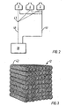
- first filling element 12 or part of the first filling element 12 is seen is fig. 3.
- Several specimen of the same tube 42 is placed side-by-side along the length axis of each other constituting a horizontal layer whereupon several other horizontal layers of tubes 42 are placed.
- the collection of tubes 42 constitutes a pile of tubes substantially with a shape of a box.
- the tubes 42 are welded together.
- the openings of the tubes 42 are perpendicular to the direction of the air stream.
- Other types of first filling elements 12 characterised in having a large surface area can also be used.
- the droplet collector 11 substantially excludes any clogging of liquid, which may arise on its surface.
- the droplet collector 11 is suspended inside the housing 6 for example by placing the droplet collector 11 on a support 13 or an open-structured bed allowing air and droplets to pass through.
- Spraying means 14 are placed below the droplet collector 11.
- a possible embodiment of the spraying means 14 is a set of spray nozzles in rows connected by a pipe section.
- the noales may be of a common type used for showers working with a low water pressure.
- the nozzles are preferably made of Teflon, polypropylene or PVS having a full cone, wide-angle non-clog construction. Certain types of nozzles being capable of providing so called atomised droplets defined as droplets with a very small droplet size is can be used but it is not necessary as the use of second filling element 16 fulfils the purpose of mixing the gaseous state with the liquid state.
- the spraying means 14 may also simply be constituted by one or more simple holes.
- the second filling element is placed below the spraying means 14 and are preferably similar in function and construction to the first filling elements 12 and may be placed on a support 17 similar to the support 13.
- the second filling element 16 constitutes part of the scrubbing zone 15 in the air cleaning unit 5.
- the first filling element 12 and the second filling element 16 are similar thus simplifying materials needed for the production of the air cleaning unit 5.
- one or more air inlets 8, 9 are placed.
- the air inlets 8, 9 may be in the shape of simple holes in the side of the housing 6 or the bottom of the housing 6. In a preferred embodiment two holes of a diameter of about 0.6 m are situated opposite each other in the walls of a housing 6 with a box-structure.
- the drain 19 may be a simple cut-out in the bottom plate of the housing 6.
- a means for shielding the drain 19 from outlet of liquid may be present below the second filling elements 16 and embodied as a bend plate whose apex is pointing away from the drain.
- means for spraying the underside of the second filling element with a liquid is present.
- a washing liquid control unit 20 is in connection with the air cleaning unit 5 via an inlet pipe 40 and an outlet pipe 41.
- the inlet pipe 40 and the outlet pipe 41 are preferably made of PVC, polypropylene or a similar polymer generally resistant to attack of acids and are suspended in steel wires in the ceiling of placed on the attic 2 dependent on the construction of the stable 1.
- the washing liquid control unit 20 is placed outside the stable 1 so that no direct air contact is possible between the washing liquid control unit 20 and the stable 1.
- the distance between the washing liquid control unit 20 and the air cleaning unit may be considerable, such as in the order of the height, length or depth of the stable itself.
- the washing liquid control unit 20 comprises a tank 21 divided into a first tank section 22 and a second tank section 23 by a partition wall 24.
- a filter 25 for filtrating a liquid in the tank 21 is forming part of the partition wall 24 so that impurities as e.g. dust and insects is hindered in clogging the spraying means 14.
- the partition wall 24 may extend in the full height inside the tank 21 from bottom to ceiling or it may end almost at the ceiling of the tank 21.
- the roof of the tank 21 is preferably easy to open fully or in part when maintenance of the inner of the tank 21 is needed.
- the filter is preferably in the shape of long slab with a length substantially that of the height of the tank 21 and a width of approx. 0.2 m and insertable in a slit in the partition wall in an up-down way.
- the filter material may be a cloth material.
- a circulation pump 26 for circulating a liquid from the first tank section 22 to the spraying means 14 is present.
- the circulation pump 26 may be a seal-less, vertical, centrifugal type pump for corrosion resistance and long service life.
- the circulation pump 26 is suitable for solutions over a broad pH range. Also, placed inside the first tank section 22, a water valve 28 is placed connected by a water pipe 30 from the water tank 29 to the first tank section 22. The level of liquid in the tank 21 controls the opening and closing of the water valve 28. In the washing liquid control unit 20, a flow gauge 27 is placed on the inlet pipe 40 constantly measuring the flow of the liquid in the inlet pipe 40, which thus can be monitored from the washing liquid control unit 20.
- An acid pipe 34 connects an acid tank 33 with the first tank section 22. The acid in the acid tank 33 is preferably sulphuric acid, H 2 SO 4 , and preferably concentrated H 2 SO 4 .
- An automated acid pump 32 controls the supply of acid to the first tank section 22.
- an antifoaming agent pipe 37 connects an antifoaming agent tank 36 with the second tank section 23.
- the antifoaming agent may be a vegetable oil, or another oil or agent characterised as an antifoaming agent, hindering the generation of foam in the liquid in the system.
- An automated antifoaming agent pump 35 controls the supply of antifoaming agent to the second tank section 23.
- the inlet of antifoaming agent into the second tank section is preferably in the upper part of the tank 21.
- An automated pump 38 for fertilizer mixture is placed in the washing liquid control unit 20 in order to drain a liquid from the second tank section 23. Possible occurring sludge in the tank can be removed from the tank by means of the outlet for the fertilizer mixture, and the outlet for the fertilizer mixture may be placed in the lower part of the tank 21.
- the fertilizer mixture is transferred to a fertilizer mixture tank 39.
- a pH meter 31 of a common type described within the state of the art is placed inside the washing liquid control unit 20 on the outlet pipe 41 constantly measuring the pH value of the liquid in the outlet pipe 41.
- the pH meter 31 is capable of generating a signal controlling the automated acid pump 32, the automated antifoaming agent pump 35 and the automated pump for the fertilizer mixture 38.
- the acid tank 33, the water tank 29 and the tank 21 for collecting the fertilizer mixture 39 is preferably placed outside both the stable 1 and the washing liquid control unit 20.
- the system will draw the air to be cleaned into one or more air cleaning units 5.
- the operation of an embodiment according to the invention with a system comprising a single air cleaning unit 5 will be described in the following. As the system comprises two parts, an air stream and a pipe system for the washing liquid the description will follow this division of the system where logical.
- the air is driven into the air cleaning unit 5 by a fan 18 in the end of the upward part of the stream, such that the air is sucked out of the building or stable 1 thereby creating a continuous flow of air while the fan 18 is in operation.
- a fan 18 By placing the fan 18 at very end of the air stream, a chimney effect can be exploited and the energy consumption of the fan 18 is relatively lower by this placement compared to a placement of the fan 18 not exploiting the chimney effect.
- the fan 18 in the upstream part of the air stream after the scrubbing zone 15 the fan 18 does not receive dust particles as compared to a construction where the fan 18 is placed in the stable 1 or building where air borne particles and dust are expected to occur.
- the air After entering the air cleaning unit 5 through one or more air inlets 8 in the bottom part of the air cleaning unit 5 the air passes the second filling element 16 on which the washing liquid is dispensed and where upon the chemical reaction between the unwanted odorous constituents is taking place. Furthermore, any gaseous and solid constituents not taking part of the chemical reaction will be dissolved or dispersed in the washing liquid.
- This part of the process is best described as a scrubbing of the air stream and is taking place in the scrubbing zone 15 of the air cleaning unit 5.
- the washing liquid is emanating from the nozzles of the spraying means 14, which is part of the pipe system. After the scrubbing zone 15, the air passes a droplet collector 11 trapping substantially all the fluid in the misty air at this point in the air cleaning unit 5.
- the droplet collector 11 has draining means for the collected fluid and the draining means leads the collected fluid back in the downstream direction of the air stream.
- the housing 6 of the air cleaning unit 5 narrows in and the air stream passes the fan 18.
- the air leaves the air cleaning unit 5 depleted of malodorous constituents through a simple hole 3 in the roof construction of the building into the open, the smell of the air being characterised as more acceptable than air emanating from a traditional stable.
- the washing liquid flows through a pipe system connected to a tank 21 with circulation for the liquid.
- the liquid is pumped through an inlet pipe 40 out of the first tank section 22 by a circulation pump 26 constantly in operation while the system operates.
- a flow gauge 27 on the inlet pipe 40 is constantly measuring the magnitude of the flow for the purpose of providing a means for supervision of the process.
- the measurement of the flow preferably constitutes a basis for a safety device discriminating between one or more magnitudes of the flow and consequently triggering an alarm for a defined critical magnitude of the flow. E.g. a relatively low value of the flow could imply a leak in the pipe system.
- the liquid is led to the air cleaning unit 5 and is leaving the inlet pipe 40 to be dispersed onto the second filling element 16 as described above.
- the liquid leaves the air cleaning unit 5 again through a drain 19 in the bottom of the air cleaning unit 5 to enter the pipe system again in an outlet pipe 41 in connection to the drain 19.
- the inlet pipe 40 and the outlet pipe 41 are thus communicating liquid into and out of the air cleaning unit 5 respectively.
- the inlet pipe 40 and the outlet pipe 41 are placed in the building where appropriate and there is a large degree of freedom when considering such construction features for the system according to the invention as the availability of the pipes for possibly occurring maintenance and safety precautions related to placement of the pipes themselves.
- the pipes are preferably made of PVC, polypropylene or a similar polymer generally resistant to attack of acids.
- the outlet pipe 41 leads the liquid from the air cleaning unit 5 to the second tank section 23 of the tank 21.
- a pH meter 31 is placed on the outlet pipe 41.
- the on-line reading of the pH value controls the automated acid pump 32, the automated antifoaming agent pump 35 and the automated pump for the fertilizer mixture 38.
- a signal is sent to the pumps in order to compensate for the deviation.
- the control mechanism implies that the acid content in the inlet pipe 40 is varying and the variation is following the ammonia content in the air such that the system has a sound use of the resources determined by the actual need.
- the variation of ammonia arises due to the daily cycle for the animals and the variations of the air circulation in the stable 1.
- the signal from the pH meter 31 controls not only the acid pump 32, but also the pump 38 for draining the fertilizer mixture and the pump 35 for addition of antifoaming agent solution.
- a single signal for the control of these three pumps is sufficient due to the fact, that a constant interrelation is pre-set for the dosage delivered by the pumps.
- the control signals to the pumps 32, 35 and 38 are connected in serial and the power control follows the principal of PID-control (Proportional Integral Differential) well known within the state of art. As a consequence of this type of control, the pumps work continually supplying a varying pump function basically controlled in magnitude by the continuously measured pH value.
- One advantageous feature for the PID-control system being exploited in a preferred embodiment according to the invention is the minimization of statistical errors related to the pH value of the drained fertilizer mixture 38.
- the statistical errors can be minimized with the addition of an integrating part of the control in the PID-control system.
- a computer such as e.g. a PC to carry out the necessary calculations involved for computing the signal to the pumps.
- Other relations than the above mentioned might be chosen for the system according to the invention.
- the actual amounts of liquids pumped per time unit depends on the size of the system, but the amounts follow the above relationship.
- the optimization of the relation follows the needs for the resulting fertilizer mixture, e.g. need for adjusting the concentration of the fertilizer substances.
- a reduction of the ammonia content of 90 %, and a reduction of the air-constituent units of 50 % was achieved together with a resulting fertilizer mixture with a concentration of 8.1 % ammonia per weight.
- the pumps 32, 35 and 38 are of a membrane pump type or a piston pump type. Other control principals than those described above may be applied for the control with the system according to the invention.
- the fertilizer mixture is collected to a fertilizer tank 39 of appropriate dimensions determined by the amount of production of the fertilizer mixture and the space available.
- the level of liquid in the tank 21 controls the opening and closing of the water valve 28.
- the two or more air cleaning units 5 may be interconnected via the pipe system and the washing liquid control unit 20.
- the inlet pipe may be divided to let the washing liquid flow to each of the air cleaning units 5.
- FIG. 3 three air cleaning units 5 connected in parallel are shown schematically. The three air cleaning units 5 share part of the inlet pipe 40 and part of the outlet pipe 41 connected to the washing liquid control unit 20.
- a pipe junction 43 is shown on the inlet pipe 40.
Landscapes
- Chemical & Material Sciences (AREA)
- Life Sciences & Earth Sciences (AREA)
- Engineering & Computer Science (AREA)
- Analytical Chemistry (AREA)
- Chemical Kinetics & Catalysis (AREA)
- Organic Chemistry (AREA)
- Oil, Petroleum & Natural Gas (AREA)
- General Chemical & Material Sciences (AREA)
- Environmental Sciences (AREA)
- Zoology (AREA)
- Biodiversity & Conservation Biology (AREA)
- Animal Husbandry (AREA)
- Manufacturing & Machinery (AREA)
- Treating Waste Gases (AREA)
- Gas Separation By Absorption (AREA)
- Separation Of Particles Using Liquids (AREA)
- Separation Of Gases By Adsorption (AREA)
- Cleaning By Liquid Or Steam (AREA)
- Working Measures On Existing Buildindgs (AREA)
- Filtering Of Dispersed Particles In Gases (AREA)
- Fertilizers (AREA)
Claims (31)
- Verfahren zur Reinigung von Ammoniak enthaltender Luft, beispielsweise aus einem Stall ausströmender Luft, durch Waschen der Luft mit einer säurehaltigen Waschflüssigkeit in mindestens zwei parallel arbeitenden Waschzonen, umfassend folgende StufenAbzug verbrauchter Waschflüssigkeit aus den Waschzonen;Überführen der abgezogenen Waschflüssigkeit zu einer in einem Abstand von mindestens 3 Metern von den Waschzonen angeordneten zentralen Waschflüssigkeits-Steuerzone;falls erwünscht, Justierung der Zusammensetzung der von den Waschzonen abgezogenen verbrauchten Waschflüssigkeit durch Zugabe von Frischwasser und frischer Säure, und Entnahme einer entsprechenden Menge der verbrauchten Waschflüssigkeit als ein Produkt; undÜberführen der wahlfrei justierten Waschflüssigkeit zu den Waschzonen als säurehaltige Waschflüssigkeit.
- Verfahren nach Anspruch 1, wonach die Abstände zwischen zentraler Waschflüssigkeits-Steuerzone und den Waschzonen zumindest 10 Meter betragen.
- Verfahren nach einem der Ansprüche 1 oder 2, wonach die Säure Schwefelsäure ist.
- Verfahren nach einem der Ansprüche 1-3, wonachder pH-Wert der von den Waschzonen abgezogenen Waschflüssigkeit festgestellt ist; unddie Justierung der Zusammensetzung der verbrauchten Waschflüssigkeit von einer Steueranordnung vorgenommen wird, welche die Menge der als Produkt abgezogenen Waschflüssigkeit pro Minute und die Menge von zugesetzter frischer Säure pro Minute steuert, so dass zwischen den zwei Mengen pro Minute ein erwünschtes, festgesetztes Verhältnis besteht.
- Verfahren nach Anspruch 4, bei welchem die Steueranordnung die Menge der als Produkt abgezogenen Waschflüssigkeit pro Minute und die Menge von zugesetzter frischer Säure pro Minute steuert, so dass diese Mengen pro Minute null sind, wenn der pH-Wert der von den Waschzonen abgezogenen Waschflüssigkeit pHdet kleiner als ein voraus festgesetzter Wert pHset ist, und erwünschte vorausbestimmte Funktionen von pHset - pHdet sind, wenn pHdet grösser als pHset ist.
- Verfahren nach Anspruch 5, wonach der Wert von pHset zwischen 2 und 6, vorzugsweise zwischen 3 und 5, und besonders zwischen 3,5 und 4,5 liegt.
- Verfahren nach einem der Ansprüche 4-6, wonach der Waschflüssigkeit mindestens ein Hilfsmittel zugesetzt wird, und bei welchem die Steueranordnung die Menge/n von zugesetztem Hilfsmittel/zugesetzten Hilfsmitteln pro Minute steuert, so dass zwischen den Mengen von zugesetztem Hilfsmittel/zugesetzten Hilfsmitteln pro Minute und der Menge von zugefügter frischer Säure pro Minute ein erwünschtes, festgesetztes Verhältnis/festgesetzte Verhältnisse vorliegt.
- Vorrichtung zur Reinigung von Ammoniak enthaltender Luft, beispielsweise aus einem Stall ausströmender Luft, durch Waschen mit einer säurehaltigen Waschflüssigkeit, umfassendmindestens zwei parallel arbeitende Luftreinigungseinheiten, die jeweils einen Schrubber umfassen, in dem die zu reinigende Luft mit der säurehaltigen Waschflüssigkeit gereinigt wird, und wovon die gereinigte Luft und die verbrauchte Waschflüssigkeit abgezogen werden; undeine zentrale Waschflüssigkeitssteuereinheit, die in einem Abstand von mindestens 3 Metern von den Luftreinigungseinheiten angeordnet ist, in welcher die Zusammensetzung der von den Luftreinigungseinheiten abgezogenen verbrauchten Waschflüssigkeit justiert wird, falls erwünscht, durch Zusatz von Frischwasser und frischer Säure und Entnahme einer entsprechenden Menge der verbrauchten Waschflüssigkeit als ein Produkt, bevor die wahlweise justierte Waschflüssigkeit zu den Luftreinigungseinheiten überführt wird und in diese als säurehaltige Waschflüssigkeit eingeleitet wird.
- Vorrichtung nach Anspruch 8, bei welcher die Abstände zwischen der zentralen Waschflüssigkeits-steuerzone und den Waschzonen mindestens 10 Meter betragen.
- Vorrichtung nach einem der Ansprüche 8 oder 9, umfassendzumindest eine Luftreinigungseinheit mit einem Schrubber, der umfassteinen Lufteinlass für die zu reinigende Lufteinen Luftauslass für gereinigte Lufteinen Waschflüssigkeitseinlaufeinen Waschflüssigkeitsauslauf;eine in einem Abstand von mindestens 3 Metern von den Luftreinigungseinheiten angeordnete Waschflüssigkeits-Steuereinheit, die umfassteinen Wassereinlaufeinen Einlass für frische Säureeinen Waschflüssigkeitseinlauf, der mit dem Waschflüssigkeitsauslauf der Schrubber in Flüssigkeitsverbindung steht,einen ersten Auslauf für Waschflüssigkeit, der mit dem Waschflüssigkeitseinlauf der Schrubber in Flüssigkeitsverbindung steht,einen zweiten Auslauf für Waschflüssigkeit, undein Steuersystem, dasdie über den zweiten Auslauf für Waschflüssigkeit abgezogene Menge von Waschflüssigkeit pro Minute steuert, unddie durch den Säureeinlass eingeführte Menge von frischer Säure pro Minute steuert.
- Vorrichtung nach Anspruch 10, bei welcher die mindestens eine Luftreinigungseinheit ferner einen Ventilator mit einem an den Luftauslass des Schrubbers angeschlossenen Lufteinlass und Luftauslass umfasst.
- Vorrichtung nach einem der Ansprüche 8-11, ferner umfassendund bei welcher Vorrichtung die Waschflüssigkeitssteuereinheit umfasstein pH-Messgerät zum Feststellen des pH-Werts der über den Waschflüssigkeitsauslauf des Schrubbers abgezogenen Waschflüssigkeit,ein Steuersystem, das den durch das pH-Messgerät festgesetztem pH-Wert als Input hat, und Steuersignale, welchedie durch den zweiten Auslauf für Waschflüssigkeit abgezogene Menge von Waschflüssigkeit pro Minute, unddie durch den Säureeinlass eingeleitete Menge von frischer Säure als Outputs steuern.
- Vorrichtung nach einem der Ansprüche 8-12, wonach die Schrubber Füllkörperabscheider sind.
- Vorrichtung nach Anspruch 13, bei welcher die Schrubber ein unter Betriebsbedingungen vertikal ausgerichtetes Gehäuse umfassen, worinder Lufteinlass in dem unteren Ende des Gehäuses, vorzugsweise auf der Seite des Gehäuses angeordnet ist;der Waschflüssigkeitsauslauf in dem unteren Ende des Gehäuses angeordnet ist;der Füllkörper über dem Lufteinlass und dem Waschflüssigkeitsauslauf angeordnet ist;Düsen zum Einleiten von Waschflüssigkeit über dem Füllkörper angeordnet sind;ein Tropfensammler über den Düsen angeordnet ist, undder Luftauslass bei dem oberen Ende des Gehäuses angeordnet ist.
- Vorrichtung nach einem der Ansprüche 8-14, wonach die Waschflüssigkeitssteuereinheit einen Tank umfasst, mitdem Wassereinlaufdem Einlass für frische Säuredem Waschflüssigkeitseinlauf in Flüssigkeitsverbindung mit dem Waschflüssigkeitsauslauf der Schrubber,dem ersten Auslauf für Waschflüssigkeit in Flüssigkeitsverbindung mit dem Waschflüssigkeitseinlauf der Schrubber, unddem zweiten Auslauf für Waschflüssigkeit.
- Vorrichtung nach Anspruch 15, wonach der Tank durch eine flüssigkeitsdurchlässige Membran in einen ersten Tankabschnitt und einen zweiten Tankabschnitt geteilt ist, und worinder Wassereinlaufder Einlass für frische Säure, undder erste Auslauf für Waschflüssigkeit in dem ersten Tankabschnitt, undder Waschflüssigkeitseinlauf, undder zweite Auslauf für Waschflüssigkeit in dem zweiten Tankabschnitt angeordnet sind.
- Vorrichtung nach einem der Ansprüche 15 oder 16, wonach der Wassereinlauf mit Mitteln zum Einleiten von Frischwasser versehen ist, welche Mittel durch einen im Tank vorgesehenen Niveauanzeiger gesteuert werden.
- Vorrichtung nach einem der Ansprüche 8-17, wonach das Waschflüssigkeits-Steuersystem mindestens einen Einlauf für Hilfsmittel umfasst.
- Vorrichtung nach Anspruch 16, wonach das Waschflüssigkeits-Steuersystem mindestens einen in dem zweiten Tankabschnitt vorgesehenen Einlauf für Hilfsmittel umfasst.
- Vorrichtung nach Anspruch 19, wonach das Steuersystem die Menge des durch den Einlauf für Hilfsmittel eingeleiteten Hilfsmittels/eingeleiteter Hilfsmittel bestimmt.
- Vorrichtung nach einem der Ansprüche 8-20, umfassend eine Pumpe für die Waschflüssigkeit zwecks Zirkulieren von Waschflüssigkeit zwischen der Luftreinigungseinheit und der Waschflüssigkeits-Steuereinheit.
- Vorrichtung nach einem der Ansprüche 8-21, umfassend fernerein pH-Messgerät zum Feststellen des pH-Werts der durch den Waschflüssigkeitsauslauf des Schrubbers entnommenen Waschflüssigkeit; undworin die Waschflüssigkeits-Steuereinheit ein Steuersystem mit einer Steueranordnung umfasst, welche die durch den zweiten Auslauf für Waschflüssigkeit entnommene Menge von Waschflüssigkeit pro Minute und die durch den Säureeinlass eingeleitete Menge frischer Säure pro Minute steuert, so dass zwischen diesen beiden Mengen pro Minute ein erwünschtes, festgesetztes Verhältnis besteht.
- Vorrichtung nach Anspruch 22, wonach die Steueranordnung die durch den zweiten Auslauf für Waschflüssigkeit entnommene Menge von Waschflüssigkeit pro Minute und die durch den Säureeinlass eingeleitete Menge frischer Säure pro Minute steuert, so dass diese Mengen null sind, wenn der durch das pH-Messgerät ermittelte pH-Wert pHdet kleiner ist als ein voraus festgesetzter Wert pHset, und erwünschte, voraus festgesetzte Funktionen von pHset - pHdet sind, wenn pHdet grösser als pHset ist.
- Vorrichtung nach Anspruch 23, wonach der Wert von pHset zwischen 2-6, vorzugsweise zwischen 3-5, und besonders zwischen 3,5-4,5 ist.
- Vorrichtung nach einem der Ansprüche 22-24, wonach das Waschflüssigkeits-Steuersystem mindestens einen Einlauf für Hilfsmittel umfasst, und bei welcher die Steueranordnung die durch den mindestens einen Einlauf für Hilfsmittel eingeführte Menge/Mengen von Hilfsmittel/n steuert, so dass zwischen der Menge/den Mengen von Hilfsmittel/n und der durch den Säureeinlass zugeführten Menge von frischer Säure ein erwünschtes, festgelegtes Verhältnis besteht.
- Bau, insbesondere ein Stall, versehen mit einem System zur Reinigung von Ammoniak enthaltender Luft, umfassendmindestens zwei parallel arbeitende und in dem oberen Teil des Baus angeordnete Luftreinigungseinheiten, wovon jede einen Schrubber umfasst, worin die zu reinigende Luft mit der säurehaltigen Waschflüssigkeit gewaschen wird, und wovon die gereinigte Luft und die verbrauchte Waschflüssigkeit entnommen werden; undeine in einem Abstand von mindestens 3 Metern von der Luftreinigungseinheit, vorzugsweise auf Bodenniveau des Baus angeordnete zentrale Waschflüssigkeits-Steuereinheit, in der die Zusammensetzung der von den Luftreinigungseinheiten abgezogenen verbrauchten Waschflüssigkeit justiert wird, falls erwünscht, durch Zugabe von Frischwasser und frischer Säure und Abzug einer entsprechenden Menge der verbrauchten Waschflüssigkeit als ein Produkt, bevor die wahlweise justierte Waschflüssigkeit zu den Luftreinigungseinheiten überführt und in diese als säurehaltige Waschflüssigkeit eingeleitet wird.
- Bau nach Anspruch 26, wonach die Abstände zwischen zentraler Waschflüssigkeits-Steuerzone und den Waschzonen mindestes 10 Meter betragen.
- Bau nach Anspruch 26 oder 27, wonach eine Luftreinigungseinheit von einer Decke im Bau aufgehängt ist.
- Bau nach einem der Ansprüche 26-28, wonach eine Luftreinigungseinheit in einem Speicher des Baus platziert ist.
- Bau nach einem der Ansprüche 26-29, wonach eine Luftreinigungseinheit oben auf dem Dach des Baus platziert ist.
- Bau, insbesondere ein Stall, nach einem der Ansprüche 26-30, wonach das System zur Reinigung von Luft die Vorrichtung nach einem der Ansprüche 10-25 umfasst.
Applications Claiming Priority (3)
| Application Number | Priority Date | Filing Date | Title |
|---|---|---|---|
| DKPA200201159 | 2002-07-30 | ||
| DK200201159 | 2002-07-30 | ||
| PCT/DK2003/000506 WO2004011127A1 (en) | 2002-07-30 | 2003-07-18 | Method of purifying air, process for manufacture of fertilizer, apparatus for purifying air and building provided with this apparatus |
Publications (3)
| Publication Number | Publication Date |
|---|---|
| EP1525044A1 EP1525044A1 (de) | 2005-04-27 |
| EP1525044B1 true EP1525044B1 (de) | 2005-10-12 |
| EP1525044B8 EP1525044B8 (de) | 2005-12-28 |
Family
ID=30775761
Family Applications (1)
| Application Number | Title | Priority Date | Filing Date |
|---|---|---|---|
| EP03737951A Expired - Lifetime EP1525044B8 (de) | 2002-07-30 | 2003-07-18 | Verfahren zur reinigung von luft, vorrichtung zur reinigung von luft und mit dieser vorrichtung versehenes gebäude |
Country Status (7)
| Country | Link |
|---|---|
| EP (1) | EP1525044B8 (de) |
| AT (1) | ATE306310T1 (de) |
| AU (1) | AU2003245871A1 (de) |
| DE (1) | DE60301890T2 (de) |
| DK (1) | DK1525044T3 (de) |
| ES (1) | ES2250900T3 (de) |
| WO (1) | WO2004011127A1 (de) |
Families Citing this family (14)
| Publication number | Priority date | Publication date | Assignee | Title |
|---|---|---|---|---|
| EP1701155B1 (de) | 2005-03-11 | 2008-10-08 | AE & E Lentjes GmbH | Verfahren und Vorrichtung zur Bestimmung des CaCO3-Gehaltes einer Waschflüssigkeit |
| EP1707876A1 (de) | 2005-03-18 | 2006-10-04 | Lurgi Lentjes AG | Im wesentlichen horizontal durchströmte Rauchgasreinigungsvorrichtung |
| EP1707875A1 (de) | 2005-03-18 | 2006-10-04 | Lurgi Lentjes AG | Rauchgasreinigungsvorrichtung mit verbesserter Oxidationseinrichtung im Waschflüssigkeitssumpf |
| EP1707877A1 (de) * | 2005-03-18 | 2006-10-04 | Lurgi Lentjes AG | Rauchgasreinigungsvorrichtung mit geteiltem Waschflüssigkeitssumpf |
| CN100451135C (zh) * | 2005-12-22 | 2009-01-14 | 攀枝花钢企工贸有限责任公司 | 用加铝及稀土生产优质碳素钢钢锭以提高锻件探伤级别的工艺 |
| GB0621789D0 (en) * | 2006-11-02 | 2006-12-13 | Leudal Holding B V | Manure dryer |
| KR101039624B1 (ko) * | 2009-11-17 | 2011-06-09 | 한국에너지기술연구원 | 암모니아수를 이용한 이산화탄소 포집 공정에서 배출되는 가스 내의 미량 암모니아를 제거하는 장치 |
| DE202010009560U1 (de) * | 2010-06-25 | 2011-10-17 | Big Dutchman International Gmbh | Abluftreinigungsvorrichtung für Nutztierställe |
| WO2014053138A2 (en) | 2012-10-05 | 2014-04-10 | Munters A/S | A method and means for the cleaning of air, in particular stable air. |
| DE202012010730U1 (de) * | 2012-11-12 | 2014-02-14 | Pal-Bullermann Gmbh | Stalleinrichtung und Abluftreinigungseinrichtung für selbige |
| US9095115B1 (en) * | 2013-08-12 | 2015-08-04 | Jones-Hamilton Co. | Animal house having ammonia control apparatus |
| US10239016B2 (en) | 2016-12-07 | 2019-03-26 | Nuorganics LLC | Systems and methods for nitrogen recovery from a gas stream |
| CA2992063A1 (en) | 2017-01-16 | 2018-07-16 | Nuorganics LLC | Systems and methods for recovering nitrogenous compounds from a gas stream |
| DE102017109562A1 (de) * | 2017-05-04 | 2018-11-08 | Martin Schönhammer | Verfahren zum Betrieb eines chemischen Abluftwäschers |
Citations (1)
| Publication number | Priority date | Publication date | Assignee | Title |
|---|---|---|---|---|
| EP1344560A2 (de) * | 2002-03-16 | 2003-09-17 | Big Dutchman International GmbH | Vorrichtung zum Behandeln wenigstens eines gasförmigen Mediums, insbesondere zum Reinigen von aus Gebäuden abgeführter Luft bzw. von in Gebäude zugeführter Luft |
Family Cites Families (4)
| Publication number | Priority date | Publication date | Assignee | Title |
|---|---|---|---|---|
| NL8900005A (nl) * | 1989-01-03 | 1990-08-01 | Cooeperatieve Nl Champignonkwe | Werkwijze voor het zuiveren van ammoniak bevattende lucht en daarbij toe te passen inrichting. |
| US6174498B1 (en) * | 1991-10-28 | 2001-01-16 | Us Filter/Rj Environmental, Inc. | Odor control system |
| NL1012530C1 (nl) * | 1999-07-07 | 2001-01-09 | Johannes Antonius Niemeijer | Luchtwasser. |
| JP2002143639A (ja) * | 2000-11-10 | 2002-05-21 | Kurita Water Ind Ltd | アンモニア含有ガスの処理方法 |
-
2003
- 2003-07-18 AU AU2003245871A patent/AU2003245871A1/en not_active Abandoned
- 2003-07-18 AT AT03737951T patent/ATE306310T1/de not_active IP Right Cessation
- 2003-07-18 EP EP03737951A patent/EP1525044B8/de not_active Expired - Lifetime
- 2003-07-18 DE DE60301890T patent/DE60301890T2/de not_active Expired - Lifetime
- 2003-07-18 DK DK03737951T patent/DK1525044T3/da active
- 2003-07-18 WO PCT/DK2003/000506 patent/WO2004011127A1/en not_active Ceased
- 2003-07-18 ES ES03737951T patent/ES2250900T3/es not_active Expired - Lifetime
Patent Citations (1)
| Publication number | Priority date | Publication date | Assignee | Title |
|---|---|---|---|---|
| EP1344560A2 (de) * | 2002-03-16 | 2003-09-17 | Big Dutchman International GmbH | Vorrichtung zum Behandeln wenigstens eines gasförmigen Mediums, insbesondere zum Reinigen von aus Gebäuden abgeführter Luft bzw. von in Gebäude zugeführter Luft |
Also Published As
| Publication number | Publication date |
|---|---|
| ATE306310T1 (de) | 2005-10-15 |
| DE60301890T2 (de) | 2006-07-27 |
| DE60301890D1 (de) | 2006-02-23 |
| AU2003245871A1 (en) | 2004-02-16 |
| EP1525044A1 (de) | 2005-04-27 |
| EP1525044B8 (de) | 2005-12-28 |
| WO2004011127A1 (en) | 2004-02-05 |
| ES2250900T3 (es) | 2006-04-16 |
| DK1525044T3 (da) | 2006-03-06 |
Similar Documents
| Publication | Publication Date | Title |
|---|---|---|
| EP1525044A1 (de) | Verfahren zur reinigung von luft, vorrichtung zur reinigung von luft und mit dieser vorrichtung versehenes gebäude | |
| KR0139530B1 (ko) | 유체역학적 연기 세척기 | |
| US3409409A (en) | Controlled ph scrubber system | |
| RU2286838C2 (ru) | Способ и устройство для выделения двуокиси серы из газа | |
| KR101740216B1 (ko) | 동역학적 접촉식 오염공기 정화장치 | |
| KR100301564B1 (ko) | 연도 폐기 가스의 탈황 장치용 세척탑 | |
| US20150086435A1 (en) | Wet Scrubber Apparatus For Ammonia Capture | |
| US6174498B1 (en) | Odor control system | |
| KR102183775B1 (ko) | 수막판을 이용한 탈취장치 | |
| EP2556879A1 (de) | Verfahren zur Überwachung der Reinigung eines Prozessgases | |
| US20230030307A1 (en) | Integrated filtration and gas floatation water treatment system and process | |
| CN209333503U (zh) | 一种污水池恶臭气体收集净化装置 | |
| US3364660A (en) | Device for intimately contacting a gas with a liquid | |
| CN114345257B (zh) | 用于炼化装置防结盐的捕集装置、系统及方法 | |
| EP0941756A1 (de) | Schronsteinvorrichtung geeignet für die Abscheidung von Staub, Schwefeloxiden und Stickstoffoxiden | |
| JP3831895B2 (ja) | 空気浄化装置 | |
| US4359907A (en) | Process monitoring apparatus and method | |
| CN220460313U (zh) | 一种组合式除臭装置 | |
| CN224221096U (zh) | 移动床滴滤碱洗池 | |
| US20220088530A1 (en) | Air scrubber having an interior air exhaust | |
| CN217119749U (zh) | 卧式湿式除尘器 | |
| US4216001A (en) | Gas scrubbing apparatus | |
| EA010270B1 (ru) | Способ очистки отходящих газов от органических соединений и устройство для его осуществления | |
| SU1583149A1 (ru) | Устройство дл мокрой очистки газов | |
| CN217855426U (zh) | 一种小风量的废气处理装置 |
Legal Events
| Date | Code | Title | Description |
|---|---|---|---|
| PUAI | Public reference made under article 153(3) epc to a published international application that has entered the european phase |
Free format text: ORIGINAL CODE: 0009012 |
|
| GRAP | Despatch of communication of intention to grant a patent |
Free format text: ORIGINAL CODE: EPIDOSNIGR1 |
|
| 17P | Request for examination filed |
Effective date: 20041109 |
|
| AK | Designated contracting states |
Kind code of ref document: A1 Designated state(s): AT BE BG CH CY CZ DE DK EE ES FI FR GB GR HU IE IT LI LU MC NL PT RO SE SI SK TR |
|
| AX | Request for extension of the european patent |
Extension state: AL LT LV MK |
|
| GRAS | Grant fee paid |
Free format text: ORIGINAL CODE: EPIDOSNIGR3 |
|
| GRAA | (expected) grant |
Free format text: ORIGINAL CODE: 0009210 |
|
| AK | Designated contracting states |
Kind code of ref document: B1 Designated state(s): AT BE BG CH CY CZ DE DK EE ES FI FR GB GR HU IE IT LI LU MC NL PT RO SE SI SK TR |
|
| AX | Request for extension of the european patent |
Extension state: AL LT LV MK |
|
| PG25 | Lapsed in a contracting state [announced via postgrant information from national office to epo] |
Ref country code: AT Free format text: LAPSE BECAUSE OF FAILURE TO SUBMIT A TRANSLATION OF THE DESCRIPTION OR TO PAY THE FEE WITHIN THE PRESCRIBED TIME-LIMIT Effective date: 20051012 Ref country code: SI Free format text: LAPSE BECAUSE OF FAILURE TO SUBMIT A TRANSLATION OF THE DESCRIPTION OR TO PAY THE FEE WITHIN THE PRESCRIBED TIME-LIMIT Effective date: 20051012 Ref country code: CZ Free format text: LAPSE BECAUSE OF FAILURE TO SUBMIT A TRANSLATION OF THE DESCRIPTION OR TO PAY THE FEE WITHIN THE PRESCRIBED TIME-LIMIT Effective date: 20051012 Ref country code: IT Free format text: LAPSE BECAUSE OF FAILURE TO SUBMIT A TRANSLATION OF THE DESCRIPTION OR TO PAY THE FEE WITHIN THE PRESCRIBED TIME-LIMIT;WARNING: LAPSES OF ITALIAN PATENTS WITH EFFECTIVE DATE BEFORE 2007 MAY HAVE OCCURRED AT ANY TIME BEFORE 2007. THE CORRECT EFFECTIVE DATE MAY BE DIFFERENT FROM THE ONE RECORDED. Effective date: 20051012 Ref country code: NL Free format text: LAPSE BECAUSE OF FAILURE TO SUBMIT A TRANSLATION OF THE DESCRIPTION OR TO PAY THE FEE WITHIN THE PRESCRIBED TIME-LIMIT Effective date: 20051012 Ref country code: LI Free format text: LAPSE BECAUSE OF FAILURE TO SUBMIT A TRANSLATION OF THE DESCRIPTION OR TO PAY THE FEE WITHIN THE PRESCRIBED TIME-LIMIT Effective date: 20051012 Ref country code: FI Free format text: LAPSE BECAUSE OF FAILURE TO SUBMIT A TRANSLATION OF THE DESCRIPTION OR TO PAY THE FEE WITHIN THE PRESCRIBED TIME-LIMIT Effective date: 20051012 Ref country code: SK Free format text: LAPSE BECAUSE OF FAILURE TO SUBMIT A TRANSLATION OF THE DESCRIPTION OR TO PAY THE FEE WITHIN THE PRESCRIBED TIME-LIMIT Effective date: 20051012 Ref country code: CH Free format text: LAPSE BECAUSE OF FAILURE TO SUBMIT A TRANSLATION OF THE DESCRIPTION OR TO PAY THE FEE WITHIN THE PRESCRIBED TIME-LIMIT Effective date: 20051012 Ref country code: RO Free format text: LAPSE BECAUSE OF FAILURE TO SUBMIT A TRANSLATION OF THE DESCRIPTION OR TO PAY THE FEE WITHIN THE PRESCRIBED TIME-LIMIT Effective date: 20051012 |
|
| REG | Reference to a national code |
Ref country code: GB Ref legal event code: FG4D |
|
| REG | Reference to a national code |
Ref country code: CH Ref legal event code: EP |
|
| REG | Reference to a national code |
Ref country code: IE Ref legal event code: FG4D |
|
| RAX | Requested extension states of the european patent have changed |
Extension state: LT Payment date: 20041109 Extension state: LV Payment date: 20041109 |
|
| RAP2 | Party data changed (patent owner data changed or rights of a patent transferred) |
Owner name: SCAN-AIRCLEAN A/S |
|
| PG25 | Lapsed in a contracting state [announced via postgrant information from national office to epo] |
Ref country code: BG Free format text: LAPSE BECAUSE OF FAILURE TO SUBMIT A TRANSLATION OF THE DESCRIPTION OR TO PAY THE FEE WITHIN THE PRESCRIBED TIME-LIMIT Effective date: 20060112 Ref country code: GR Free format text: LAPSE BECAUSE OF FAILURE TO SUBMIT A TRANSLATION OF THE DESCRIPTION OR TO PAY THE FEE WITHIN THE PRESCRIBED TIME-LIMIT Effective date: 20060112 Ref country code: SE Free format text: LAPSE BECAUSE OF FAILURE TO SUBMIT A TRANSLATION OF THE DESCRIPTION OR TO PAY THE FEE WITHIN THE PRESCRIBED TIME-LIMIT Effective date: 20060112 |
|
| NLT2 | Nl: modifications (of names), taken from the european patent patent bulletin |
Owner name: SCAN-AIRCLEAN A/S Effective date: 20051130 |
|
| REF | Corresponds to: |
Ref document number: 60301890 Country of ref document: DE Date of ref document: 20060223 Kind code of ref document: P |
|
| REG | Reference to a national code |
Ref country code: DK Ref legal event code: T3 |
|
| PG25 | Lapsed in a contracting state [announced via postgrant information from national office to epo] |
Ref country code: PT Free format text: LAPSE BECAUSE OF FAILURE TO SUBMIT A TRANSLATION OF THE DESCRIPTION OR TO PAY THE FEE WITHIN THE PRESCRIBED TIME-LIMIT Effective date: 20060313 |
|
| LTIE | Lt: invalidation of european patent or patent extension |
Effective date: 20051012 |
|
| NLV1 | Nl: lapsed or annulled due to failure to fulfill the requirements of art. 29p and 29m of the patents act | ||
| PG25 | Lapsed in a contracting state [announced via postgrant information from national office to epo] |
Ref country code: HU Free format text: LAPSE BECAUSE OF FAILURE TO SUBMIT A TRANSLATION OF THE DESCRIPTION OR TO PAY THE FEE WITHIN THE PRESCRIBED TIME-LIMIT Effective date: 20060413 |
|
| REG | Reference to a national code |
Ref country code: ES Ref legal event code: FG2A Ref document number: 2250900 Country of ref document: ES Kind code of ref document: T3 |
|
| REG | Reference to a national code |
Ref country code: CH Ref legal event code: PL |
|
| ET | Fr: translation filed | ||
| PG25 | Lapsed in a contracting state [announced via postgrant information from national office to epo] |
Ref country code: IE Free format text: LAPSE BECAUSE OF NON-PAYMENT OF DUE FEES Effective date: 20060718 |
|
| PLBI | Opposition filed |
Free format text: ORIGINAL CODE: 0009260 |
|
| PG25 | Lapsed in a contracting state [announced via postgrant information from national office to epo] |
Ref country code: MC Free format text: LAPSE BECAUSE OF NON-PAYMENT OF DUE FEES Effective date: 20060731 |
|
| PLAX | Notice of opposition and request to file observation + time limit sent |
Free format text: ORIGINAL CODE: EPIDOSNOBS2 |
|
| 26 | Opposition filed |
Opponent name: WESSELMANN ENERGIE SYSTEME GMBH Effective date: 20060712 |
|
| PLAF | Information modified related to communication of a notice of opposition and request to file observations + time limit |
Free format text: ORIGINAL CODE: EPIDOSCOBS2 |
|
| PLBB | Reply of patent proprietor to notice(s) of opposition received |
Free format text: ORIGINAL CODE: EPIDOSNOBS3 |
|
| REG | Reference to a national code |
Ref country code: IE Ref legal event code: MM4A |
|
| PG25 | Lapsed in a contracting state [announced via postgrant information from national office to epo] |
Ref country code: EE Free format text: LAPSE BECAUSE OF FAILURE TO SUBMIT A TRANSLATION OF THE DESCRIPTION OR TO PAY THE FEE WITHIN THE PRESCRIBED TIME-LIMIT Effective date: 20051012 |
|
| PG25 | Lapsed in a contracting state [announced via postgrant information from national office to epo] |
Ref country code: TR Free format text: LAPSE BECAUSE OF FAILURE TO SUBMIT A TRANSLATION OF THE DESCRIPTION OR TO PAY THE FEE WITHIN THE PRESCRIBED TIME-LIMIT Effective date: 20051012 Ref country code: LU Free format text: LAPSE BECAUSE OF NON-PAYMENT OF DUE FEES Effective date: 20060718 |
|
| PG25 | Lapsed in a contracting state [announced via postgrant information from national office to epo] |
Ref country code: CY Free format text: LAPSE BECAUSE OF FAILURE TO SUBMIT A TRANSLATION OF THE DESCRIPTION OR TO PAY THE FEE WITHIN THE PRESCRIBED TIME-LIMIT Effective date: 20051012 |
|
| 29U | Proceedings interrupted after grant according to rule 142 epc |
Effective date: 20081215 |
|
| 29W | Proceedings resumed after grant [after interruption of proceedings according to rule 142 epc] |
Effective date: 20120801 |
|
| PLAB | Opposition data, opponent's data or that of the opponent's representative modified |
Free format text: ORIGINAL CODE: 0009299OPPO |
|
| R26 | Opposition filed (corrected) |
Opponent name: WESSELMANN ENERGIE SYSTEME GMBH Effective date: 20060712 |
|
| RAP2 | Party data changed (patent owner data changed or rights of a patent transferred) |
Owner name: INNO+ B.V. Owner name: MHJ AGROTEKNIK A/S Owner name: SOERENSEN, KARSTEN |
|
| PLCK | Communication despatched that opposition was rejected |
Free format text: ORIGINAL CODE: EPIDOSNREJ1 |
|
| PLBN | Opposition rejected |
Free format text: ORIGINAL CODE: 0009273 |
|
| STAA | Information on the status of an ep patent application or granted ep patent |
Free format text: STATUS: OPPOSITION REJECTED |
|
| 27O | Opposition rejected |
Effective date: 20121112 |
|
| REG | Reference to a national code |
Ref country code: DE Ref legal event code: R100 Ref document number: 60301890 Country of ref document: DE Effective date: 20121112 |
|
| REG | Reference to a national code |
Ref country code: FR Ref legal event code: PLFP Year of fee payment: 13 |
|
| REG | Reference to a national code |
Ref country code: FR Ref legal event code: PLFP Year of fee payment: 14 |
|
| REG | Reference to a national code |
Ref country code: FR Ref legal event code: PLFP Year of fee payment: 15 |
|
| REG | Reference to a national code |
Ref country code: DE Ref legal event code: R081 Ref document number: 60301890 Country of ref document: DE Owner name: INNO+ B.V., NL Free format text: FORMER OWNER: SCAN-AIRCLEAN AS, ODENSE, DK Ref country code: DE Ref legal event code: R082 Ref document number: 60301890 Country of ref document: DE Representative=s name: UEXKUELL & STOLBERG PARTNERSCHAFT VON PATENT- , DE Ref country code: DE Ref legal event code: R081 Ref document number: 60301890 Country of ref document: DE Owner name: LNNO+ HOLDING BV, NL Free format text: FORMER OWNER: SCAN-AIRCLEAN AS, ODENSE, DK |
|
| REG | Reference to a national code |
Ref country code: GB Ref legal event code: 732E Free format text: REGISTERED BETWEEN 20171116 AND 20171122 |
|
| REG | Reference to a national code |
Ref country code: ES Ref legal event code: PC2A Owner name: INNO + HOLDING BV Effective date: 20180110 |
|
| REG | Reference to a national code |
Ref country code: ES Ref legal event code: PC2A Owner name: INNO + HOLDING BV Effective date: 20180202 |
|
| REG | Reference to a national code |
Ref country code: BE Ref legal event code: HC Owner name: MHJ AGROTEKNIK A/S; DK Free format text: DETAILS ASSIGNMENT: CHANGE OF OWNER(S), CHANGEMENT DE NOM DU PROPRIETAIRE, JYDEN DEVIENT MHJ; FORMER OWNER NAME: JYDEN - MHJ A/S Effective date: 20171213 Ref country code: BE Ref legal event code: PD Owner name: INNO+ HOLDING B.V.; NL Free format text: DETAILS ASSIGNMENT: CHANGE OF OWNER(S), CESSION; FORMER OWNER NAME: JYDEN BUR A/S Effective date: 20171213 |
|
| REG | Reference to a national code |
Ref country code: FR Ref legal event code: CA Effective date: 20180319 Ref country code: FR Ref legal event code: CD Owner name: INNO+ HOLDING BV, NL Effective date: 20180319 Ref country code: FR Ref legal event code: TP Owner name: INNO+ HOLDING BV, NL Effective date: 20180319 Ref country code: FR Ref legal event code: TQ Owner name: INNO+ HOLDING BV, NL Effective date: 20180319 |
|
| REG | Reference to a national code |
Ref country code: FR Ref legal event code: PLFP Year of fee payment: 16 |
|
| REG | Reference to a national code |
Ref country code: ES Ref legal event code: PC2A Owner name: INNO + B.V. Effective date: 20210621 |
|
| REG | Reference to a national code |
Ref country code: BE Ref legal event code: PD Owner name: INNO+ B.V.; NL Free format text: DETAILS ASSIGNMENT: CHANGE OF OWNER(S), ASSIGNMENT; FORMER OWNER NAME: INNO+ HOLDING B.V. Effective date: 20210520 |
|
| REG | Reference to a national code |
Ref country code: DE Ref legal event code: R081 Ref document number: 60301890 Country of ref document: DE Owner name: INNO+ B.V., NL Free format text: FORMER OWNER: LNNO+ HOLDING BV, PANNINGEN, NL |
|
| REG | Reference to a national code |
Ref country code: GB Ref legal event code: 732E Free format text: REGISTERED BETWEEN 20210722 AND 20210728 |
|
| PGFP | Annual fee paid to national office [announced via postgrant information from national office to epo] |
Ref country code: GB Payment date: 20220720 Year of fee payment: 20 Ref country code: ES Payment date: 20220921 Year of fee payment: 20 Ref country code: DK Payment date: 20220725 Year of fee payment: 20 Ref country code: DE Payment date: 20220720 Year of fee payment: 20 |
|
| PGFP | Annual fee paid to national office [announced via postgrant information from national office to epo] |
Ref country code: FR Payment date: 20220720 Year of fee payment: 20 Ref country code: BE Payment date: 20220720 Year of fee payment: 20 |
|
| P01 | Opt-out of the competence of the unified patent court (upc) registered |
Effective date: 20230424 |
|
| REG | Reference to a national code |
Ref country code: DE Ref legal event code: R071 Ref document number: 60301890 Country of ref document: DE |
|
| REG | Reference to a national code |
Ref country code: DK Ref legal event code: EUP Expiry date: 20230718 |
|
| REG | Reference to a national code |
Ref country code: ES Ref legal event code: FD2A Effective date: 20230727 |
|
| REG | Reference to a national code |
Ref country code: GB Ref legal event code: PE20 Expiry date: 20230717 |
|
| REG | Reference to a national code |
Ref country code: BE Ref legal event code: MK Effective date: 20230718 |
|
| PG25 | Lapsed in a contracting state [announced via postgrant information from national office to epo] |
Ref country code: GB Free format text: LAPSE BECAUSE OF EXPIRATION OF PROTECTION Effective date: 20230717 Ref country code: ES Free format text: LAPSE BECAUSE OF EXPIRATION OF PROTECTION Effective date: 20230719 |