EP1524426A2 - Adapterstück für die Naturgaseinspritzung - Google Patents
Adapterstück für die Naturgaseinspritzung Download PDFInfo
- Publication number
- EP1524426A2 EP1524426A2 EP04255391A EP04255391A EP1524426A2 EP 1524426 A2 EP1524426 A2 EP 1524426A2 EP 04255391 A EP04255391 A EP 04255391A EP 04255391 A EP04255391 A EP 04255391A EP 1524426 A2 EP1524426 A2 EP 1524426A2
- Authority
- EP
- European Patent Office
- Prior art keywords
- socket
- port
- gaseous fuel
- intake manifold
- adaptor
- Prior art date
- Legal status (The legal status is an assumption and is not a legal conclusion. Google has not performed a legal analysis and makes no representation as to the accuracy of the status listed.)
- Withdrawn
Links
Images



Classifications
-
- F—MECHANICAL ENGINEERING; LIGHTING; HEATING; WEAPONS; BLASTING
- F02—COMBUSTION ENGINES; HOT-GAS OR COMBUSTION-PRODUCT ENGINE PLANTS
- F02M—SUPPLYING COMBUSTION ENGINES IN GENERAL WITH COMBUSTIBLE MIXTURES OR CONSTITUENTS THEREOF
- F02M35/00—Combustion-air cleaners, air intakes, intake silencers, or induction systems specially adapted for, or arranged on, internal-combustion engines
- F02M35/10—Air intakes; Induction systems
- F02M35/10209—Fluid connections to the air intake system; their arrangement of pipes, valves or the like
- F02M35/10216—Fuel injectors; Fuel pipes or rails; Fuel pumps or pressure regulators
-
- F—MECHANICAL ENGINEERING; LIGHTING; HEATING; WEAPONS; BLASTING
- F02—COMBUSTION ENGINES; HOT-GAS OR COMBUSTION-PRODUCT ENGINE PLANTS
- F02M—SUPPLYING COMBUSTION ENGINES IN GENERAL WITH COMBUSTIBLE MIXTURES OR CONSTITUENTS THEREOF
- F02M21/00—Apparatus for supplying engines with non-liquid fuels, e.g. gaseous fuels stored in liquid form
- F02M21/02—Apparatus for supplying engines with non-liquid fuels, e.g. gaseous fuels stored in liquid form for gaseous fuels
- F02M21/0218—Details on the gaseous fuel supply system, e.g. tanks, valves, pipes, pumps, rails, injectors or mixers
- F02M21/0248—Injectors
- F02M21/0278—Port fuel injectors for single or multipoint injection into the air intake system
-
- F—MECHANICAL ENGINEERING; LIGHTING; HEATING; WEAPONS; BLASTING
- F02—COMBUSTION ENGINES; HOT-GAS OR COMBUSTION-PRODUCT ENGINE PLANTS
- F02M—SUPPLYING COMBUSTION ENGINES IN GENERAL WITH COMBUSTIBLE MIXTURES OR CONSTITUENTS THEREOF
- F02M21/00—Apparatus for supplying engines with non-liquid fuels, e.g. gaseous fuels stored in liquid form
- F02M21/02—Apparatus for supplying engines with non-liquid fuels, e.g. gaseous fuels stored in liquid form for gaseous fuels
- F02M21/0218—Details on the gaseous fuel supply system, e.g. tanks, valves, pipes, pumps, rails, injectors or mixers
- F02M21/0248—Injectors
- F02M21/0281—Adapters, sockets or the like to mount injection valves onto engines; Fuel guiding passages between injectors and the air intake system or the combustion chamber
-
- F—MECHANICAL ENGINEERING; LIGHTING; HEATING; WEAPONS; BLASTING
- F02—COMBUSTION ENGINES; HOT-GAS OR COMBUSTION-PRODUCT ENGINE PLANTS
- F02M—SUPPLYING COMBUSTION ENGINES IN GENERAL WITH COMBUSTIBLE MIXTURES OR CONSTITUENTS THEREOF
- F02M35/00—Combustion-air cleaners, air intakes, intake silencers, or induction systems specially adapted for, or arranged on, internal-combustion engines
- F02M35/10—Air intakes; Induction systems
-
- F—MECHANICAL ENGINEERING; LIGHTING; HEATING; WEAPONS; BLASTING
- F02—COMBUSTION ENGINES; HOT-GAS OR COMBUSTION-PRODUCT ENGINE PLANTS
- F02M—SUPPLYING COMBUSTION ENGINES IN GENERAL WITH COMBUSTIBLE MIXTURES OR CONSTITUENTS THEREOF
- F02M35/00—Combustion-air cleaners, air intakes, intake silencers, or induction systems specially adapted for, or arranged on, internal-combustion engines
- F02M35/10—Air intakes; Induction systems
- F02M35/10006—Air intakes; Induction systems characterised by the position of elements of the air intake system in direction of the air intake flow, i.e. between ambient air inlet and supply to the combustion chamber
- F02M35/10078—Connections of intake systems to the engine
- F02M35/10085—Connections of intake systems to the engine having a connecting piece, e.g. a flange, between the engine and the air intake being foreseen with a throttle valve, fuel injector, mixture ducts or the like
-
- F—MECHANICAL ENGINEERING; LIGHTING; HEATING; WEAPONS; BLASTING
- F02—COMBUSTION ENGINES; HOT-GAS OR COMBUSTION-PRODUCT ENGINE PLANTS
- F02M—SUPPLYING COMBUSTION ENGINES IN GENERAL WITH COMBUSTIBLE MIXTURES OR CONSTITUENTS THEREOF
- F02M35/00—Combustion-air cleaners, air intakes, intake silencers, or induction systems specially adapted for, or arranged on, internal-combustion engines
- F02M35/10—Air intakes; Induction systems
- F02M35/104—Intake manifolds
- F02M35/112—Intake manifolds for engines with cylinders all in one line
-
- F—MECHANICAL ENGINEERING; LIGHTING; HEATING; WEAPONS; BLASTING
- F02—COMBUSTION ENGINES; HOT-GAS OR COMBUSTION-PRODUCT ENGINE PLANTS
- F02M—SUPPLYING COMBUSTION ENGINES IN GENERAL WITH COMBUSTIBLE MIXTURES OR CONSTITUENTS THEREOF
- F02M69/00—Low-pressure fuel-injection apparatus ; Apparatus with both continuous and intermittent injection; Apparatus injecting different types of fuel
- F02M69/04—Injectors peculiar thereto
- F02M69/042—Positioning of injectors with respect to engine, e.g. in the air intake conduit
- F02M69/044—Positioning of injectors with respect to engine, e.g. in the air intake conduit for injecting into the intake conduit downstream of an air throttle valve
-
- Y—GENERAL TAGGING OF NEW TECHNOLOGICAL DEVELOPMENTS; GENERAL TAGGING OF CROSS-SECTIONAL TECHNOLOGIES SPANNING OVER SEVERAL SECTIONS OF THE IPC; TECHNICAL SUBJECTS COVERED BY FORMER USPC CROSS-REFERENCE ART COLLECTIONS [XRACs] AND DIGESTS
- Y02—TECHNOLOGIES OR APPLICATIONS FOR MITIGATION OR ADAPTATION AGAINST CLIMATE CHANGE
- Y02T—CLIMATE CHANGE MITIGATION TECHNOLOGIES RELATED TO TRANSPORTATION
- Y02T10/00—Road transport of goods or passengers
- Y02T10/10—Internal combustion engine [ICE] based vehicles
- Y02T10/30—Use of alternative fuels, e.g. biofuels
Definitions
- the present invention relates to a system for adapting an existing gasoline fuel engine to also receive gaseous fuel.
- bi-fuel engines for vehicles that is engines adapted to run using gasoline fuels such as petrol, and gaseous fuel such as compressed natural gas (CNG).
- gasoline fuels such as petrol
- CNG compressed natural gas
- US6550459 discusses the introduction of a gas fuel system to an engine having a proven gasoline fuel injection system, whereby a separate injector block is created, and separate feed lines lead to an adapter plate.
- the adapter plate includes gas distributors which feed the gaseous fuel into each port of the intake manifold.
- this system still requires adaptation of the intake manifold to accommodate the new adapter plate, as well as consideration as to the accommodation and integrity of the individual feed lines.
- One object of the present invention is to provide a simpler adaptation of a gasoline fuel engine to accommodating a gaseous fuel injector system.
- an adaptor socket for connecting a gaseous fuel injector to a port in an intake manifold or flange of an internal combustion engine, said socket being adapted to fit said port and having a mounting aperture for mounting a gaseous fuel injector such that the gaseous fuel injector can inject gaseous fuel into said intake manifold via said port.
- the manifold port is an existing port, which can be adapted for use in a gaseous fuel injection system by use of the present invention.
- existing manifold ports may include de-activation ports.
- Some intake manifolds are currently designed with a port de-activation (PDA) system, although other existing manifold ports could be used.
- PDA port de-activation
- the socket extends into said port.
- the portion of the socket which extends into said port terminates in a face adapted to form a continuation of the inner surface of intake manifold adjacent the port into which the socket is inserted to ensure smooth airflow within the manifold.
- the socket also includes a securing flange or portion permitting the socket to be secured to the intake manifold.
- the gaseous fuel is compressed natural gas (CNG).
- CNG compressed natural gas
- the socket further comprises means for enhancing the mixing of gaseous fuel and air within the intake manifold, said means comprising a lip or extension provided or formed on the socket, said lip extending into the path or passageway of incoming air within the manifold, upstream of a spray nozzle of the fuel injector.
- an intake manifold or flange having one or more gaseous fuel injector sockets as hereinbefore described.
- an internal combustion engine having a gasoline fuel system and one or more further manifold ports, wherein the or each further manifold port includes a gaseous fuel injector socket as hereinbefore described.
- figure 1 shows an existing Z16 XEP flange part 2 of the intake manifold.
- a port de-activation system is provided using rotating flaps inserted through ports 4 provided in the manifold or flange 2.
- Each flap is rotatably mounted with a respective intake port or duct 16 of the flange using a plastic lever 6 biased by a spring clip 8.
- the levers 6 are actuated by a metallic link piece 10 which is operated by a pneumatic actuator 12 at one end.
- the metal strip 10 is connected to the flaps using clips 14, and the position of the flaps can be sensed using sensors located under each flap.
- Each flap can selectively covers an intake duct 16.
- the ducts 16 are shown more clearly in Figure 2.
- the present invention involves using the same ports 4 that exist in the flange 2 for the introduction of gaseous fuel injectors as shown in Figure 3.
- Gaseous fuel injectors 24 such as those shown in Figure 3 are known in the art, and are shown in Figure 3 as being supplied by a fuel rail 26.
- each port 4 there is provided a gaseous fuel injector socket 22 which can be secured to the flange 2 using the existing fixing holes 27.
- Figure 4 shows the general manifold 28 of the Z16 XEP engine. Attached to the manifold 26 is the flange 2. It can be seen in Figure 4 that there is little room, either on the manifold 28 or on the flange 2, to provide any space for a separate fuel injector system, without redesign of the manifold or flange. Redesign, either by new casting or machining is a significant exercise, which the present invention avoids. Indeed, by replacing the port de-activation system as shown in Figure 1, no new casting or machining is required, avoiding costs at this level.
- Figure 5 shows a cross sectional view of the flange 2, port 4, injector socket 22, CNG fuel injector 24, and the fuel rail 26.
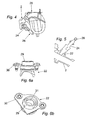
- FIGS 6a and 6b show views of the injector socket 22.
- a socket 22 can easily be formed by plastic injection moulding or the like, at relatively low cost, and having ease of fittment into the port 4.
- limited new tooling is required to effect the ability of the engine to which the flange 2 is attached to now have a gasoline fuel system and a gaseous fuel system.
- FIGS 6a and 6b show socket 22 comprising a gaseous fuel injector receiving portion 29, and a port connection portion 30.
- a fuel injector mounting aperture 31 is provided within the receiving portion 29 of the socket 22 for insertion of the lower portion of a gaseous fuel injector 24.
- the longitudinal axis of the mounting aperture 31 is inclined with respect to the axis of the port 4 within which the socket 20 is received such that the gaseous fuel injector directs fuel in a downstream direction into the flow of air in the intake duct 16 of the flange 2 to improve fuel and air mixing within the duct 16, as best seen in Figure 5.
- Figure 7a shows a further view of the socket 22 and attached injector 24.
- the position of the injector 24 in relation to the airflow, as schematically shown in Figure 7b, is important in order to achieve a good mixture of the gaseous fuel and the air.
- the particular positioning of the injector 24 can even have an impact on the packaging of the injectors in the air intake system, leading to limiting packaging restrictions. If the packaging around the flange or the manifold does not allow the injector spray angle to best match the airflow direction, this can result in the spray of injected fuel into the airflow being 'too straight', which will compromise the intention to best mix the air and fuel prior to their ignition.
- the present invention also provides a fuel injector socket 40 as shown in Figure 8a, having a port connection portion 42, and a modified port entry portion 44.
- the modification include the introduction of a lip 46 in the port entry portion 44, so as to deflect air flow within the intake duct 16 and direct the injected fuel into a more aligned path with the air flow as better shown schematically in Figure 8b. Greater alignment of the injected fuel with the airflow increases the intermixing of the components, and thus their better combustion.
- this lip 46 can vary, and would be tailored for each particular situation in terms of configuration of the flange or manifold, port, etc.
- the lip 46 is formed integrally with the rest of the socket piece 40, thereby reducing costs and increasing ease of installation.
- the present invention provides simple but effective enhancements to existing engines, both to allow the introduction of gaseous fuel, and for better mixing of the fuel and air, particularly in a restricted packaging volume.
Landscapes
- Engineering & Computer Science (AREA)
- Chemical & Material Sciences (AREA)
- Combustion & Propulsion (AREA)
- Mechanical Engineering (AREA)
- General Engineering & Computer Science (AREA)
- Chemical Kinetics & Catalysis (AREA)
- General Chemical & Material Sciences (AREA)
- Oil, Petroleum & Natural Gas (AREA)
- Fuel-Injection Apparatus (AREA)
Applications Claiming Priority (4)
| Application Number | Priority Date | Filing Date | Title |
|---|---|---|---|
| GB0323944A GB0323944D0 (en) | 2003-10-13 | 2003-10-13 | Compressed natural gas injection system |
| GB0323944 | 2003-10-13 | ||
| GB0326548 | 2003-11-14 | ||
| GB0326548A GB0326548D0 (en) | 2003-10-13 | 2003-11-14 | Compressed natural gas injection system |
Publications (2)
| Publication Number | Publication Date |
|---|---|
| EP1524426A2 true EP1524426A2 (de) | 2005-04-20 |
| EP1524426A3 EP1524426A3 (de) | 2008-07-16 |
Family
ID=34379503
Family Applications (1)
| Application Number | Title | Priority Date | Filing Date |
|---|---|---|---|
| EP04255391A Withdrawn EP1524426A3 (de) | 2003-10-13 | 2004-09-04 | Adapterstück für die Naturgaseinspritzung |
Country Status (1)
| Country | Link |
|---|---|
| EP (1) | EP1524426A3 (de) |
Cited By (2)
| Publication number | Priority date | Publication date | Assignee | Title |
|---|---|---|---|---|
| GB2422406A (en) * | 2005-01-22 | 2006-07-26 | Christopher Seaton | Adapter for fitting fuel injectors in an i.c. engine converted to run on an alternative fuel, eg gas |
| CN103195591A (zh) * | 2012-01-05 | 2013-07-10 | 铃木株式会社 | 双燃料发动机 |
Family Cites Families (5)
| Publication number | Priority date | Publication date | Assignee | Title |
|---|---|---|---|---|
| US5713336A (en) * | 1995-01-24 | 1998-02-03 | Woodward Governor Company | Method and apparatus for providing multipoint gaseous fuel injection to an internal combustion engine |
| ES2117897T3 (es) * | 1996-02-16 | 1998-08-16 | Fiat Ricerche | Motor de combustion interna con sistema de inyeccion de metano. |
| US5673673A (en) * | 1996-04-30 | 1997-10-07 | Servojet Products International | Method and apparatus for the high Mach injection of a gaseous fuel into an internal combustion engine |
| FR2770876B1 (fr) * | 1997-11-10 | 1999-12-24 | Renault | Dispositif d'injection de carburant pour moteur a combustion interne |
| CA2279149C (en) * | 1999-07-30 | 2003-04-22 | James Mancuso | Fuel injector adaptor for conversion of single fuel engines to dual fuel engines |
-
2004
- 2004-09-04 EP EP04255391A patent/EP1524426A3/de not_active Withdrawn
Cited By (3)
| Publication number | Priority date | Publication date | Assignee | Title |
|---|---|---|---|---|
| GB2422406A (en) * | 2005-01-22 | 2006-07-26 | Christopher Seaton | Adapter for fitting fuel injectors in an i.c. engine converted to run on an alternative fuel, eg gas |
| CN103195591A (zh) * | 2012-01-05 | 2013-07-10 | 铃木株式会社 | 双燃料发动机 |
| CN103195591B (zh) * | 2012-01-05 | 2015-11-25 | 铃木株式会社 | 双燃料发动机 |
Also Published As
| Publication number | Publication date |
|---|---|
| EP1524426A3 (de) | 2008-07-16 |
Similar Documents
| Publication | Publication Date | Title |
|---|---|---|
| US7886713B2 (en) | Lower intake manifold with charge motion control valve | |
| CN1298968C (zh) | 具有窜缸混合气再循环系统的内燃机 | |
| EP1156206A2 (de) | Einlasskrümmer mit innerer Brennstoffleiste und Einspritzventilen | |
| EP0933518A2 (de) | Mischplatte für eine Brennkraftmaschine | |
| EP1304473A3 (de) | Ansaugvorrichtung für Mehrzylinderbrennkraftmaschine | |
| EP1138901A3 (de) | Kraftstoffversorgungssystem für eine Brennkraftmaschine | |
| CN107429636B (zh) | 具有废气再循环的气体燃料混合器 | |
| CN103161611A (zh) | 压缩天然气发动机的独立燃料喷射系统 | |
| JPH08193547A (ja) | V型多気筒エンジンの吸気装置 | |
| US7926473B2 (en) | Air supply system for an internal combustion engine | |
| CA2293040A1 (en) | Dual fuel system for internal combustion engine | |
| KR102472495B1 (ko) | 엔진 장치 | |
| US9394862B2 (en) | Interface part between a motor vehicle engine head and a heat exchanger | |
| EP1258614B1 (de) | Brennkraftmaschine mit mehreren Zylindern | |
| JPH1182197A (ja) | 内燃機関の吸気装置 | |
| US9074528B2 (en) | Bi-fuel engine for vehicle | |
| CN117287323A (zh) | 进料组件 | |
| EP1681459B1 (de) | Kraftstoffzufuhrvorrichtung, fahrzeug und kraftstoffzufuhrvorrichtungsmontageverfahren | |
| CN1944999B (zh) | 内燃机的涡流系统进气歧管 | |
| CN110410244A (zh) | 具有一体化的水喷射喷嘴的进气歧管 | |
| EP1028250A3 (de) | Kraftstoffeinspritzvorrichtung für Brennkraftmaschine mit Direkteinspritzung | |
| US8061332B1 (en) | Fuel rail and wiring harness management assembly | |
| RU2493426C2 (ru) | Устройство впрыскивания топлива | |
| CN212202291U (zh) | 发动机的燃料供给装置 | |
| CA2359203A1 (en) | Gaseous fuel system for bi-fuel engines |
Legal Events
| Date | Code | Title | Description |
|---|---|---|---|
| PUAI | Public reference made under article 153(3) epc to a published international application that has entered the european phase |
Free format text: ORIGINAL CODE: 0009012 |
|
| AK | Designated contracting states |
Kind code of ref document: A2 Designated state(s): AT BE BG CH CY CZ DE DK EE ES FI FR GB GR HU IE IT LI LU MC NL PL PT RO SE SI SK TR |
|
| AX | Request for extension of the european patent |
Extension state: AL HR LT LV MK |
|
| PUAL | Search report despatched |
Free format text: ORIGINAL CODE: 0009013 |
|
| AK | Designated contracting states |
Kind code of ref document: A3 Designated state(s): AT BE BG CH CY CZ DE DK EE ES FI FR GB GR HU IE IT LI LU MC NL PL PT RO SE SI SK TR |
|
| AX | Request for extension of the european patent |
Extension state: AL HR LT LV MK |
|
| AKX | Designation fees paid | ||
| REG | Reference to a national code |
Ref country code: DE Ref legal event code: 8566 |
|
| STAA | Information on the status of an ep patent application or granted ep patent |
Free format text: STATUS: THE APPLICATION IS DEEMED TO BE WITHDRAWN |
|
| 18D | Application deemed to be withdrawn |
Effective date: 20090117 |