EP1524419A1 - Luftansaugkanalsystem - Google Patents
Luftansaugkanalsystem Download PDFInfo
- Publication number
- EP1524419A1 EP1524419A1 EP04024238A EP04024238A EP1524419A1 EP 1524419 A1 EP1524419 A1 EP 1524419A1 EP 04024238 A EP04024238 A EP 04024238A EP 04024238 A EP04024238 A EP 04024238A EP 1524419 A1 EP1524419 A1 EP 1524419A1
- Authority
- EP
- European Patent Office
- Prior art keywords
- air intake
- intake duct
- bearing element
- duct system
- flap
- Prior art date
- Legal status (The legal status is an assumption and is not a legal conclusion. Google has not performed a legal analysis and makes no representation as to the accuracy of the status listed.)
- Withdrawn
Links
- 238000002485 combustion reaction Methods 0.000 claims abstract description 7
- 239000000853 adhesive Substances 0.000 description 1
- 230000001070 adhesive effect Effects 0.000 description 1
- 230000006378 damage Effects 0.000 description 1
- 230000001747 exhibiting effect Effects 0.000 description 1
- 238000003780 insertion Methods 0.000 description 1
- 230000037431 insertion Effects 0.000 description 1
Images


Classifications
-
- F—MECHANICAL ENGINEERING; LIGHTING; HEATING; WEAPONS; BLASTING
- F02—COMBUSTION ENGINES; HOT-GAS OR COMBUSTION-PRODUCT ENGINE PLANTS
- F02M—SUPPLYING COMBUSTION ENGINES IN GENERAL WITH COMBUSTIBLE MIXTURES OR CONSTITUENTS THEREOF
- F02M35/00—Combustion-air cleaners, air intakes, intake silencers, or induction systems specially adapted for, or arranged on, internal-combustion engines
- F02M35/10—Air intakes; Induction systems
- F02M35/1034—Manufacturing and assembling intake systems
- F02M35/10354—Joining multiple sections together
-
- F—MECHANICAL ENGINEERING; LIGHTING; HEATING; WEAPONS; BLASTING
- F02—COMBUSTION ENGINES; HOT-GAS OR COMBUSTION-PRODUCT ENGINE PLANTS
- F02B—INTERNAL-COMBUSTION PISTON ENGINES; COMBUSTION ENGINES IN GENERAL
- F02B27/00—Use of kinetic or wave energy of charge in induction systems, or of combustion residues in exhaust systems, for improving quantity of charge or for increasing removal of combustion residues
- F02B27/02—Use of kinetic or wave energy of charge in induction systems, or of combustion residues in exhaust systems, for improving quantity of charge or for increasing removal of combustion residues the systems having variable, i.e. adjustable, cross-sectional areas, chambers of variable volume, or like variable means
- F02B27/0205—Use of kinetic or wave energy of charge in induction systems, or of combustion residues in exhaust systems, for improving quantity of charge or for increasing removal of combustion residues the systems having variable, i.e. adjustable, cross-sectional areas, chambers of variable volume, or like variable means characterised by the charging effect
- F02B27/0215—Oscillating pipe charging, i.e. variable intake pipe length charging
-
- F—MECHANICAL ENGINEERING; LIGHTING; HEATING; WEAPONS; BLASTING
- F02—COMBUSTION ENGINES; HOT-GAS OR COMBUSTION-PRODUCT ENGINE PLANTS
- F02B—INTERNAL-COMBUSTION PISTON ENGINES; COMBUSTION ENGINES IN GENERAL
- F02B27/00—Use of kinetic or wave energy of charge in induction systems, or of combustion residues in exhaust systems, for improving quantity of charge or for increasing removal of combustion residues
- F02B27/02—Use of kinetic or wave energy of charge in induction systems, or of combustion residues in exhaust systems, for improving quantity of charge or for increasing removal of combustion residues the systems having variable, i.e. adjustable, cross-sectional areas, chambers of variable volume, or like variable means
- F02B27/0226—Use of kinetic or wave energy of charge in induction systems, or of combustion residues in exhaust systems, for improving quantity of charge or for increasing removal of combustion residues the systems having variable, i.e. adjustable, cross-sectional areas, chambers of variable volume, or like variable means characterised by the means generating the charging effect
- F02B27/0247—Plenum chambers; Resonance chambers or resonance pipes
- F02B27/0257—Rotatable plenum chambers
-
- F—MECHANICAL ENGINEERING; LIGHTING; HEATING; WEAPONS; BLASTING
- F02—COMBUSTION ENGINES; HOT-GAS OR COMBUSTION-PRODUCT ENGINE PLANTS
- F02B—INTERNAL-COMBUSTION PISTON ENGINES; COMBUSTION ENGINES IN GENERAL
- F02B27/00—Use of kinetic or wave energy of charge in induction systems, or of combustion residues in exhaust systems, for improving quantity of charge or for increasing removal of combustion residues
- F02B27/02—Use of kinetic or wave energy of charge in induction systems, or of combustion residues in exhaust systems, for improving quantity of charge or for increasing removal of combustion residues the systems having variable, i.e. adjustable, cross-sectional areas, chambers of variable volume, or like variable means
- F02B27/0226—Use of kinetic or wave energy of charge in induction systems, or of combustion residues in exhaust systems, for improving quantity of charge or for increasing removal of combustion residues the systems having variable, i.e. adjustable, cross-sectional areas, chambers of variable volume, or like variable means characterised by the means generating the charging effect
- F02B27/0247—Plenum chambers; Resonance chambers or resonance pipes
- F02B27/0263—Plenum chambers; Resonance chambers or resonance pipes the plenum chamber and at least one of the intake ducts having a common wall, and the intake ducts wrap partially around the plenum chamber, i.e. snail-type
-
- F—MECHANICAL ENGINEERING; LIGHTING; HEATING; WEAPONS; BLASTING
- F02—COMBUSTION ENGINES; HOT-GAS OR COMBUSTION-PRODUCT ENGINE PLANTS
- F02D—CONTROLLING COMBUSTION ENGINES
- F02D9/00—Controlling engines by throttling air or fuel-and-air induction conduits or exhaust conduits
- F02D9/08—Throttle valves specially adapted therefor; Arrangements of such valves in conduits
- F02D9/10—Throttle valves specially adapted therefor; Arrangements of such valves in conduits having pivotally-mounted flaps
- F02D9/109—Throttle valves specially adapted therefor; Arrangements of such valves in conduits having pivotally-mounted flaps having two or more flaps
- F02D9/1095—Rotating on a common axis, e.g. having a common shaft
-
- F—MECHANICAL ENGINEERING; LIGHTING; HEATING; WEAPONS; BLASTING
- F02—COMBUSTION ENGINES; HOT-GAS OR COMBUSTION-PRODUCT ENGINE PLANTS
- F02M—SUPPLYING COMBUSTION ENGINES IN GENERAL WITH COMBUSTIBLE MIXTURES OR CONSTITUENTS THEREOF
- F02M35/00—Combustion-air cleaners, air intakes, intake silencers, or induction systems specially adapted for, or arranged on, internal-combustion engines
- F02M35/10—Air intakes; Induction systems
- F02M35/10006—Air intakes; Induction systems characterised by the position of elements of the air intake system in direction of the air intake flow, i.e. between ambient air inlet and supply to the combustion chamber
- F02M35/10026—Plenum chambers
- F02M35/10039—Intake ducts situated partly within or on the plenum chamber housing
-
- F—MECHANICAL ENGINEERING; LIGHTING; HEATING; WEAPONS; BLASTING
- F02—COMBUSTION ENGINES; HOT-GAS OR COMBUSTION-PRODUCT ENGINE PLANTS
- F02M—SUPPLYING COMBUSTION ENGINES IN GENERAL WITH COMBUSTIBLE MIXTURES OR CONSTITUENTS THEREOF
- F02M35/00—Combustion-air cleaners, air intakes, intake silencers, or induction systems specially adapted for, or arranged on, internal-combustion engines
- F02M35/10—Air intakes; Induction systems
- F02M35/10091—Air intakes; Induction systems characterised by details of intake ducts: shapes; connections; arrangements
- F02M35/10111—Substantially V-, C- or U-shaped ducts in direction of the flow path
-
- F—MECHANICAL ENGINEERING; LIGHTING; HEATING; WEAPONS; BLASTING
- F02—COMBUSTION ENGINES; HOT-GAS OR COMBUSTION-PRODUCT ENGINE PLANTS
- F02M—SUPPLYING COMBUSTION ENGINES IN GENERAL WITH COMBUSTIBLE MIXTURES OR CONSTITUENTS THEREOF
- F02M35/00—Combustion-air cleaners, air intakes, intake silencers, or induction systems specially adapted for, or arranged on, internal-combustion engines
- F02M35/10—Air intakes; Induction systems
- F02M35/10091—Air intakes; Induction systems characterised by details of intake ducts: shapes; connections; arrangements
- F02M35/10144—Connections of intake ducts to each other or to another device
-
- F—MECHANICAL ENGINEERING; LIGHTING; HEATING; WEAPONS; BLASTING
- F02—COMBUSTION ENGINES; HOT-GAS OR COMBUSTION-PRODUCT ENGINE PLANTS
- F02M—SUPPLYING COMBUSTION ENGINES IN GENERAL WITH COMBUSTIBLE MIXTURES OR CONSTITUENTS THEREOF
- F02M35/00—Combustion-air cleaners, air intakes, intake silencers, or induction systems specially adapted for, or arranged on, internal-combustion engines
- F02M35/10—Air intakes; Induction systems
- F02M35/10242—Devices or means connected to or integrated into air intakes; Air intakes combined with other engine or vehicle parts
- F02M35/10268—Heating, cooling or thermal insulating means
-
- F—MECHANICAL ENGINEERING; LIGHTING; HEATING; WEAPONS; BLASTING
- F02—COMBUSTION ENGINES; HOT-GAS OR COMBUSTION-PRODUCT ENGINE PLANTS
- F02M—SUPPLYING COMBUSTION ENGINES IN GENERAL WITH COMBUSTIBLE MIXTURES OR CONSTITUENTS THEREOF
- F02M35/00—Combustion-air cleaners, air intakes, intake silencers, or induction systems specially adapted for, or arranged on, internal-combustion engines
- F02M35/10—Air intakes; Induction systems
- F02M35/104—Intake manifolds
- F02M35/108—Intake manifolds with primary and secondary intake passages
- F02M35/1085—Intake manifolds with primary and secondary intake passages the combustion chamber having multiple intake valves
-
- F—MECHANICAL ENGINEERING; LIGHTING; HEATING; WEAPONS; BLASTING
- F02—COMBUSTION ENGINES; HOT-GAS OR COMBUSTION-PRODUCT ENGINE PLANTS
- F02M—SUPPLYING COMBUSTION ENGINES IN GENERAL WITH COMBUSTIBLE MIXTURES OR CONSTITUENTS THEREOF
- F02M35/00—Combustion-air cleaners, air intakes, intake silencers, or induction systems specially adapted for, or arranged on, internal-combustion engines
- F02M35/10—Air intakes; Induction systems
- F02M35/104—Intake manifolds
- F02M35/116—Intake manifolds for engines with cylinders in V-arrangement or arranged oppositely relative to the main shaft
-
- Y—GENERAL TAGGING OF NEW TECHNOLOGICAL DEVELOPMENTS; GENERAL TAGGING OF CROSS-SECTIONAL TECHNOLOGIES SPANNING OVER SEVERAL SECTIONS OF THE IPC; TECHNICAL SUBJECTS COVERED BY FORMER USPC CROSS-REFERENCE ART COLLECTIONS [XRACs] AND DIGESTS
- Y02—TECHNOLOGIES OR APPLICATIONS FOR MITIGATION OR ADAPTATION AGAINST CLIMATE CHANGE
- Y02T—CLIMATE CHANGE MITIGATION TECHNOLOGIES RELATED TO TRANSPORTATION
- Y02T10/00—Road transport of goods or passengers
- Y02T10/10—Internal combustion engine [ICE] based vehicles
- Y02T10/12—Improving ICE efficiencies
Definitions
- the invention relates to an air intake duct system for motor vehicle internal combustion engines.
- the air intake duct system for V-engines suitable.
- Switching flaps serve to vary the length of intake ducts.
- a known from DE 196 14 474 Heilansaugkanalsystem has for each Cylinder on a spiral-shaped air intake duct. This takes place the intake of air through a central, within the spiral Inlet ducts arranged collecting inlet channel.
- collection intake duct becomes air sucked in and over the individual air intake ducts to the engine directed.
- a Shorting channel provided. This open with a switching flap and lockable short-circuit channel is with the collecting inlet channel and respectively connected to an air intake passage.
- the individual switching flaps are over one common wave interconnected.
- the bearing of the shaft takes place in the housing of the air intake duct system.
- the Air intake duct system on two housing halves, wherein the shift shaft is inserted between the housing halves.
- the object of the invention is an air intake duct system for To provide internal combustion engines, in which the risk of loosing Fastening elements reduced, preferably excluded.
- An air intake duct system has a plurality of air intake ducts passing through a plurality, in particular two housing parts are formed.
- the air intake ducts are with individual combustion chambers of the internal combustion engine, in which it is In particular, a series or V-engine, connected. to Change in the flow behavior and / or the Lucasansaugkanalin
- Each air intake channel has a flap.
- the flaps can be For example, act throttle, swirl, tambling and / or switching flaps.
- the flaps are each within an air intake duct arranged so that the flap shaft is located in the air intake passage and the flap is mounted centrally in the channel.
- a Bearing element provided which carries at least one flap.
- the Bearing element has a first locking element, which with a second on the Housing part provided latching element for fastening of the bearing element in the housing part cooperates.
- the bearing element carries the flap, i. the Flap shaft connected to the flap.
- the flap shaft is in the Bearing element arranged such that the flap by the bearing element worn.
- the locking element channel-forming is. This has the advantage that the design of the housing parts is simplified and in the housing part no narrow slots or openings to Insertion of the first adhesive element must be provided. An in Direction of the intake passage facing surface of the first locking element thus forms the channel inner wall.
- the first locking element designed so that no edges or heels on the inside of the Channels that could lead to undesirable turbulence.
- a single bearing element carries a plurality of flaps.
- flaps for example, in a V-type engine, there are two rows of cylinders and thus also provided two rows of flaps, each with a common Bearing element are stored.
- the flaps for each one Series of the V engine on a common shaft are stored.
- the two flap waves by a single bear common bearing element. This particular has in the assembly considerable advantages, since the assembly is simplified and executed faster can be.
- the flap and the flap shaft or the flaps and the common Folding shaft are preferably formed in one piece. This has the advantage that no fasteners for securing the flap or the flaps are required on the valve shaft.
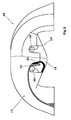
- An air intake duct system has a housing part 10, in which several Air intake ducts 12 are formed. When connecting the housing part 10th with a second housing part, the intake ports 12 to in in Circumferentially formed closed air intake ducts. Within the Air intake ducts are openings 14 which are formed by not shown Flaps can be closed. The valves are in the illustrated embodiment by switching flaps, through which the length of the Air intake ducts 12 can be varied.
- the flaps are mounted in a common bearing element 16, wherein the Bearing element 16 in the illustrated embodiment for storage all the flaps of a intake duct system for a V-engine is used.
- the bearing element openings 18, 20, wherein the openings or Bearing 18 and the openings or bearings 20 in each case one behind the other are arranged and serve for storage in each case a flap shaft.
- flaps are alternately from the one and the other flap shaft carried.
- By turning the respective Damper shaft thus become all damper positions of those channels changed, arranged in series to those on one side of the V-engine Cylinders lead.
- By mounted in the bearings 20 valve shaft which are leading in the to the other series of the V-engine Air intake ducts mounted flaps worn and pivoted together.
- the two flap shafts can be connected to one another common, uniform opening and closing of the flaps enable.
- the bearing element 16 has a plurality of first latching elements 22 on.
- the locking elements 22 are arcuate and have an in Direction of the air intake channel facing convex portion 24. At this joins a Rasthacken 26 exhibiting part.
- the convex Channel-forming configuration of the first locking element 22 is the Rasthacken in a certain range elastically deformable, as indicated by the arrow 28th indicated.
- a bearing part 36 of the bearing member 16 For mounting the bearing shafts in the openings or bearing receivers 18, 20 is a bearing part 36 of the bearing member 16 with this via a film hinge 38th connected, so that the bearing part 36 for inserting the flap shaft in Direction of an arrow 40 can be opened.
- a film hinge 38 may also be a separate one in the bearing part Part act that, for example, at a contact surface 42 with the Bearing element 18 is glued. It is also possible to store the To realize flap shaft in the openings 28 by mounting syringes.
- the channel-forming first latching elements 22 preferably extend over the entire channel width (Fig. 3), wherein each air intake passage 12 only one Locking element 22 is provided.
- the secure fixation of the bearing element 16 in the housing part 10 is ensured, for example, that the Locking elements 22 adjacent air intake ducts 12 to each other are aligned.
- the channel-forming surface of the locking element 22 includes adjacent latching elements 22 thus in the opposite direction.
- the openings 18, 20 for supporting the flap shafts in lugs provided in accordance with the recesses 30 of the housing part 10th intervene and are guided herein.
- the position of the bearing element 16 additionally defined in the housing part 10. Since it is the first Locking element 22 is preferably a channel-forming locking element is the second latching element 32 preferably completely from the first Locking element 22 covers (Fig. 2).
- bearing element 16 in the preferred embodiment for storage all flaps is used and it is in the illustrated embodiment is an air intake duct system for V-engines, is the bearing element 16 preferably zigzag-shaped, wherein the bearing element constructed according to juxtaposed U's whose open side alternately facing in opposite directions.
Landscapes
- Engineering & Computer Science (AREA)
- Chemical & Material Sciences (AREA)
- Combustion & Propulsion (AREA)
- Mechanical Engineering (AREA)
- General Engineering & Computer Science (AREA)
- Manufacturing & Machinery (AREA)
- Characterised By The Charging Evacuation (AREA)
- Control Of Throttle Valves Provided In The Intake System Or In The Exhaust System (AREA)
Abstract
Description
- Fig. 1
- eine schematische teilweise geschnittene Seitenansicht eines Gehäuseteils und des Lagerelements vor der Montage,
- Fig. 2
- eine schematische teilweise geschnittene Seitenansicht des Gehäuseteils und des Lagerelements in eingebautem Zustand, und
- Fig. 3
- eine schematische perspektivische Ansicht des Gehäuseteils mit montiertem Lagerelement.
Claims (10)
- Luftansaugkanalsystem für Brennkraftmaschinen, mitwobei das Lagerelement (16) ein erstes Rastelement (22) aufweist, das mit einem zweiten an dem Gehäuseteil (10) vorgesehenen Rastelement (32) zur Befestigung des Lagerelements (16) zusammenwirkt.mehreren Luftansaugkanälen (12) bildenden Gehäuseteilen (10),jeweils eine je Luftansaugkanal (12) vorgesehenen Klappe undeinem mindestens eine Klappe tragenden Lagerelement (16),
- Luftansaugkanalsystem nach Anspruch 1, dadurch gekennzeichnet, dass das erste Rastelement (22) kanalbildend ausgestaltet ist.
- Luftansaugkanalsystem nach Anspruch 1 oder 2, dadurch gekennzeichnet, dass das erste Rastelement (22) sich über die gesamte Breite des Luftansaugkanals (12) erstreckt.
- Luftansaugkanalsystem nach einem der Ansprüche 1 bis 3, dadurch gekennzeichnet, dass das erste Rastelement (22) in Richtung des Luftansaugkanals (12) konvex ausgebildet ist.
- Luftansaugkanalsystem nach einem der Ansprüche 1 bis 4, dadurch gekennzeichnet, dass das erste Rastelement (22) das zweite Rastelement (32) überdeckt.
- Luftansaugkanalsystem nach einem der Ansprüche 1 bis 5, dadurch gekennzeichnet, dass das Lagerelement (16) mehrere, insbesondere alle Klappen trägt.
- Luftansaugkanalsystem nach einem der Ansprüche 1 bis 6, dadurch gekennzeichnet, dass das Lagerelement (16) zwei Klappenwellen trägt.
- Luftansaugkanalsystem nach Anspruch 6 oder 7, dadurch gekennzeichnet, dass das Lagerelement zickzackförmig ausgebildet ist.
- Luftansaugkanalsystem nach einem der Ansprüche 1 bis 8, dadurch gekennzeichnet, dass benachbarte erste Rastelemente (22) aufeinander zu ausgerichtet sind.
- Luftansaugkanalsystem nach einem der Ansprüche 1 bis 9, dadurch gekennzeichnet, dass das Lagerelement (16) einstückig ausgebildet ist.
Applications Claiming Priority (2)
| Application Number | Priority Date | Filing Date | Title |
|---|---|---|---|
| DE10347574 | 2003-10-14 | ||
| DE10347574A DE10347574B3 (de) | 2003-10-14 | 2003-10-14 | Luftansaugkanalsystem |
Publications (1)
| Publication Number | Publication Date |
|---|---|
| EP1524419A1 true EP1524419A1 (de) | 2005-04-20 |
Family
ID=33441830
Family Applications (1)
| Application Number | Title | Priority Date | Filing Date |
|---|---|---|---|
| EP04024238A Withdrawn EP1524419A1 (de) | 2003-10-14 | 2004-10-12 | Luftansaugkanalsystem |
Country Status (2)
| Country | Link |
|---|---|
| EP (1) | EP1524419A1 (de) |
| DE (1) | DE10347574B3 (de) |
Citations (4)
| Publication number | Priority date | Publication date | Assignee | Title |
|---|---|---|---|---|
| US4854271A (en) * | 1985-09-09 | 1989-08-08 | Honda Giken Kogyo Kabushiki Kaisha | Intake manifold assembly for engines |
| US5211139A (en) * | 1992-09-08 | 1993-05-18 | Siemens Automotive Limited | Active manifold |
| US6446591B1 (en) * | 1999-10-12 | 2002-09-10 | Siemens Vdo Automotive Inc. | Air gap filler for a multi-portion air directing manifold |
| EP1264974A1 (de) * | 2001-05-15 | 2002-12-11 | Honda Giken Kogyo Kabushiki Kaisha | Einlasssystem für eine mehrzylindrige Brennkraftmaschine |
Family Cites Families (2)
| Publication number | Priority date | Publication date | Assignee | Title |
|---|---|---|---|---|
| DE19614474B4 (de) * | 1996-04-12 | 2005-08-04 | Pierburg Gmbh | Luftansaugkanalsystem für Brennkraftmaschinen |
| DE10137077C2 (de) * | 2001-07-28 | 2003-05-28 | Pierburg Gmbh | Luftansaugkanalsystem für Brennkraftmaschinen |
-
2003
- 2003-10-14 DE DE10347574A patent/DE10347574B3/de not_active Expired - Fee Related
-
2004
- 2004-10-12 EP EP04024238A patent/EP1524419A1/de not_active Withdrawn
Patent Citations (4)
| Publication number | Priority date | Publication date | Assignee | Title |
|---|---|---|---|---|
| US4854271A (en) * | 1985-09-09 | 1989-08-08 | Honda Giken Kogyo Kabushiki Kaisha | Intake manifold assembly for engines |
| US5211139A (en) * | 1992-09-08 | 1993-05-18 | Siemens Automotive Limited | Active manifold |
| US6446591B1 (en) * | 1999-10-12 | 2002-09-10 | Siemens Vdo Automotive Inc. | Air gap filler for a multi-portion air directing manifold |
| EP1264974A1 (de) * | 2001-05-15 | 2002-12-11 | Honda Giken Kogyo Kabushiki Kaisha | Einlasssystem für eine mehrzylindrige Brennkraftmaschine |
Also Published As
| Publication number | Publication date |
|---|---|
| DE10347574B3 (de) | 2004-12-16 |
Similar Documents
| Publication | Publication Date | Title |
|---|---|---|
| DE60121108T2 (de) | Einlasskrümmer einer Brennkraftmaschine | |
| DE69317581T2 (de) | Aktive luftanzugsanlage | |
| DE19811051B4 (de) | Luftansaugeinrichtung für einen Verbrennungsmotor | |
| DE10212596A1 (de) | Variable Einlassvorrichtung für einen Mehrzylinderverbrennungsmotor | |
| DE19614474B4 (de) | Luftansaugkanalsystem für Brennkraftmaschinen | |
| WO1999017012A1 (de) | Schalldämpfer mit einem nebenschlussresonator | |
| EP0492122B1 (de) | Luftansauganlage für eine Brennkraftmaschine | |
| DE102010036726A1 (de) | Variable Ansaugkanalstruktur eines Motors | |
| DE102005031393A1 (de) | Variabler Einlasskrümmer mit einem Steuerventil zur Resonanzabstimmung in drei Betriebsarten | |
| DE60203475T2 (de) | Drosselklappe und Drossel | |
| DE10347574B3 (de) | Luftansaugkanalsystem | |
| DE102007007111A1 (de) | Klappenventil | |
| EP1388652B1 (de) | Ansaugkanalsystem | |
| DE10101412B4 (de) | Abgasrückführeinrichtung für eine Brennkraftmaschine | |
| DE19709882B4 (de) | Schaltwalze | |
| EP1296051B1 (de) | Luftansaugkanalsystem | |
| DE102009043627A1 (de) | Ansaugeinrichtung für Verbrennungsmotoren | |
| DE102011103841A1 (de) | Klappenventilanordnung und Herstellungsverfahren | |
| DE10319403A1 (de) | Klappenvorrichtung | |
| WO2016102256A1 (de) | Ventil zur steuerung eines gasstroms, flüssigkeitsabscheider, entlüftungssystem und verbrennungsmotor mit einem derartigen ventil | |
| DE202005011254U1 (de) | Saugmodul, insbesondere für eine Brennkraftmaschine | |
| DE4113248A1 (de) | Luftansauganlage fuer otto-brennkraftmaschinen | |
| EP1251253A2 (de) | Schaltverband zum Verschluss von Saugkanälen einer Ansaugvorrichtung | |
| DE10352096B4 (de) | Zylinderkopf für eine Hubkolben-Brennkraftmaschine | |
| DE19612036B4 (de) | Saugrohranlage für eine mehrzylindrige Brennkraftmaschine in V-Anordnung |
Legal Events
| Date | Code | Title | Description |
|---|---|---|---|
| PUAI | Public reference made under article 153(3) epc to a published international application that has entered the european phase |
Free format text: ORIGINAL CODE: 0009012 |
|
| AK | Designated contracting states |
Kind code of ref document: A1 Designated state(s): AT BE BG CH CY CZ DE DK EE ES FI FR GB GR HU IE IT LI LU MC NL PL PT RO SE SI SK TR |
|
| AX | Request for extension of the european patent |
Extension state: AL HR LT LV MK |
|
| 17P | Request for examination filed |
Effective date: 20050406 |
|
| AKX | Designation fees paid |
Designated state(s): AT BE BG CH CY CZ DE DK EE ES FI FR GB GR HU IE IT LI LU MC NL PL PT RO SE SI SK TR |
|
| 17Q | First examination report despatched |
Effective date: 20060928 |
|
| STAA | Information on the status of an ep patent application or granted ep patent |
Free format text: STATUS: THE APPLICATION IS DEEMED TO BE WITHDRAWN |
|
| 18D | Application deemed to be withdrawn |
Effective date: 20110502 |