EP1524418A1 - Method for controlling a fan with multiple characteristics and control program for the power control of the fan - Google Patents
Method for controlling a fan with multiple characteristics and control program for the power control of the fan Download PDFInfo
- Publication number
- EP1524418A1 EP1524418A1 EP04023782A EP04023782A EP1524418A1 EP 1524418 A1 EP1524418 A1 EP 1524418A1 EP 04023782 A EP04023782 A EP 04023782A EP 04023782 A EP04023782 A EP 04023782A EP 1524418 A1 EP1524418 A1 EP 1524418A1
- Authority
- EP
- European Patent Office
- Prior art keywords
- fan
- control
- fan motor
- filter
- characteristic
- Prior art date
- Legal status (The legal status is an assumption and is not a legal conclusion. Google has not performed a legal analysis and makes no representation as to the accuracy of the status listed.)
- Withdrawn
Links
- 238000000034 method Methods 0.000 title claims abstract description 28
- 238000013016 damping Methods 0.000 claims abstract description 6
- 238000001816 cooling Methods 0.000 claims description 51
- 238000002485 combustion reaction Methods 0.000 claims description 39
- 230000008859 change Effects 0.000 claims description 15
- 230000001105 regulatory effect Effects 0.000 claims description 11
- 238000012423 maintenance Methods 0.000 abstract 2
- 239000000498 cooling water Substances 0.000 description 36
- 235000006506 Brasenia schreberi Nutrition 0.000 description 12
- 238000010586 diagram Methods 0.000 description 9
- 239000002826 coolant Substances 0.000 description 8
- 230000008569 process Effects 0.000 description 8
- 238000010438 heat treatment Methods 0.000 description 5
- 238000013021 overheating Methods 0.000 description 5
- 230000004913 activation Effects 0.000 description 3
- 230000008901 benefit Effects 0.000 description 3
- 230000001276 controlling effect Effects 0.000 description 3
- 230000000694 effects Effects 0.000 description 3
- 230000006870 function Effects 0.000 description 3
- 238000012544 monitoring process Methods 0.000 description 3
- 230000009993 protective function Effects 0.000 description 3
- 238000013459 approach Methods 0.000 description 2
- 238000012545 processing Methods 0.000 description 2
- 238000005070 sampling Methods 0.000 description 2
- 239000000725 suspension Substances 0.000 description 2
- 230000002123 temporal effect Effects 0.000 description 2
- 230000003213 activating effect Effects 0.000 description 1
- 238000005265 energy consumption Methods 0.000 description 1
- 230000007613 environmental effect Effects 0.000 description 1
- 239000000446 fuel Substances 0.000 description 1
- 230000003993 interaction Effects 0.000 description 1
- 230000007246 mechanism Effects 0.000 description 1
- 238000004377 microelectronic Methods 0.000 description 1
- 230000001960 triggered effect Effects 0.000 description 1
- 238000011144 upstream manufacturing Methods 0.000 description 1
- 230000003936 working memory Effects 0.000 description 1
Images


Classifications
-
- F—MECHANICAL ENGINEERING; LIGHTING; HEATING; WEAPONS; BLASTING
- F01—MACHINES OR ENGINES IN GENERAL; ENGINE PLANTS IN GENERAL; STEAM ENGINES
- F01P—COOLING OF MACHINES OR ENGINES IN GENERAL; COOLING OF INTERNAL-COMBUSTION ENGINES
- F01P7/00—Controlling of coolant flow
- F01P7/02—Controlling of coolant flow the coolant being cooling-air
- F01P7/04—Controlling of coolant flow the coolant being cooling-air by varying pump speed, e.g. by changing pump-drive gear ratio
- F01P7/048—Controlling of coolant flow the coolant being cooling-air by varying pump speed, e.g. by changing pump-drive gear ratio using electrical drives
-
- F—MECHANICAL ENGINEERING; LIGHTING; HEATING; WEAPONS; BLASTING
- F01—MACHINES OR ENGINES IN GENERAL; ENGINE PLANTS IN GENERAL; STEAM ENGINES
- F01P—COOLING OF MACHINES OR ENGINES IN GENERAL; COOLING OF INTERNAL-COMBUSTION ENGINES
- F01P2023/00—Signal processing; Details thereof
-
- F—MECHANICAL ENGINEERING; LIGHTING; HEATING; WEAPONS; BLASTING
- F01—MACHINES OR ENGINES IN GENERAL; ENGINE PLANTS IN GENERAL; STEAM ENGINES
- F01P—COOLING OF MACHINES OR ENGINES IN GENERAL; COOLING OF INTERNAL-COMBUSTION ENGINES
- F01P2023/00—Signal processing; Details thereof
- F01P2023/08—Microprocessor; Microcomputer
-
- F—MECHANICAL ENGINEERING; LIGHTING; HEATING; WEAPONS; BLASTING
- F01—MACHINES OR ENGINES IN GENERAL; ENGINE PLANTS IN GENERAL; STEAM ENGINES
- F01P—COOLING OF MACHINES OR ENGINES IN GENERAL; COOLING OF INTERNAL-COMBUSTION ENGINES
- F01P7/00—Controlling of coolant flow
- F01P7/14—Controlling of coolant flow the coolant being liquid
- F01P7/16—Controlling of coolant flow the coolant being liquid by thermostatic control
- F01P7/167—Controlling of coolant flow the coolant being liquid by thermostatic control by adjusting the pre-set temperature according to engine parameters, e.g. engine load, engine speed
Definitions
- the invention relates to a method for power control a fan motor and a control program with which the Power control of the fan motor is performed.
- method and control program are particularly suitable for Control of fan motors, as with fans in cooling systems be used for internal combustion engines.
- the control program determines the fan power based on Characteristics of the fan motor as well as the operating parameters of the cooling system and on the basis of predetermined reference variables, which specify a temperature level to be regulated.
- method and control program are here but in none Limited way to cooling systems in motor vehicles, but can always be used, if it applies, with one Fan motor to regulate different temperature levels.
- a generic method and a generic control program are from the German patent application DE 197 28 814 A1.
- the to be set Temperature levels are the reference variables for this Fan controller, which with a control program the required Fan power determined.
- the fan power is determined from the operating parameters of the cooling system, the predetermined reference variable. As well as from maps and Characteristics of the fan motor. The operation of the fan will in this case suspended until the coolant in the cooling system has reached and exceeded a minimum temperature. This is to ensure that the internal combustion engine comes as soon as possible to operating temperature and a Cooling effect of the fan motor can not prematurely use.
- the fan function Once the fan function is enabled, it fits Control program the fan power to be regulated Temperature level. There are in particular two temperature levels of 90 degrees Celsius and 108 degrees Celsius provided, to which the fan power is to be adapted.
- the aforementioned power control is thus an efficient one Process the temperature levels specified as reference variables to reach as soon as possible. Disadvantages arise However, if from a high temperature level to a low temperature level to be changed. The change the temperature level is namely by changing the reference variable specified for the power control. This reference makes a step of 108 degrees Celsius to 95 degrees Celsius. For the power control of the fan motor This means that he is due to the large temperature difference when changing the reference variable from a high one to a low value a large temperature difference to current actual temperature determines it applies as possible compensate quickly. This means that the fan motor with maximum power. While this has the advantage that the low temperature level is reached as quickly as possible is, but is usually neither desired nor necessary. The whine of the fan motor therefore leads to a noise annoyance and to an unnecessary energy consumption.
- the invention does it is the task, in the case of a change of the one to be regulated Temperature levels from a high level to a low level Value to prevent a whining of the fan motor.
- the solution works mainly with a power control, when the fan power from the characteristics of the fan motor, the operating parameters of the cooling system and the determined in the form of temperature levels predetermined reference variables becomes.
- the different temperature levels to be regulated Here are different characteristics for the control assigned to the fan motor.
- Changes the reference variable for the control this also means a change of Characteristic curves for controlling the fan motor.
- To a howl the fan motor is prevented when changing the Reference variable for the fan control the operation of the fan motor kept constant for an adjustable minimum waiting time becomes. During this minimum waiting time, the operating parameters may change of the cooling system, if necessary by others control mechanisms independent of the fan to the new reference variable have adjusted so far that a howl of the Fan motor is no longer to get.
- the Start-up of the fan motor with a filter in the control the fan motor is switched on, damped.
- this filter has a so-called PT1 characteristic.
- Further advantageous embodiments of the invention include the possibility of the minimum waiting time until the onset of Fan motor and the way of any necessary Fan start-up adapted to the system conditions.
- the minimum waiting time depending on the thermal load of the system to be cooled be shortened or the filter characteristics, with which the startup of the fan motor is influenced targeted be changed so that the fan faster to larger Achievements goes up.
- a sensor monitoring of the the system to be cooled and the ambient conditions can be Duration of the effectiveness of an adjusted filter setting be reduced when the environmental conditions too much change than that the selected filter settings would still be useful.
- this is the minimum waiting time for the suspension of the fan motor depending on of the temperature level to be regulated or the current one Operating parameters set.
- the filter settings depending on the current operating parameters set are the minimum waiting time for the suspension of the fan motor depending on of the temperature level to be regulated or the current one Operating parameters set.
- the invention is particularly suitable for use in cooling systems of internal combustion engines.
- the relevant operating parameters according to which the filter settings and the minimum waiting time to be selected currently applied engine load of the internal combustion engine and the Intake air temperature of the internal combustion engine.
- fan motors are used as a safeguard against overheating a system to be cooled used.
- the thing to cool System usually has besides the fan control a primary temperature control. With this primary temperature control the temperature in the cooling system is preferably controlled.
- thermostats work much more energy-saving than fan motors and have the advantage of being in the system Keep energy better in the system.
- fan motors This has the disadvantage that they consume a lot of energy only for the purpose of taking energy out of an existing system. However, it is better to use the energy in the system too leave and try to derive as much active power as possible to be able to remove.
- the temperature control in a cooling system Therefore, it is preferably done with an energy-saving Primary control, while the fan motor and fan control to be used only as an additional backup, if with the primary control a reliable temperature control can no longer be met.
- the fan In particular in Motor vehicles should therefore the fan as possible at all not used for temperature control in the cooling system.
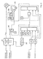
- known fan controllers from the prior art However, problems arise when, as at the beginning already stated, the temperature level in a cooling system from a high value to a lower temperature level should be lowered. These problems are based on Figure 1 clearly illustrated and it is at the same time the advantageous Operation of a fan control according to the invention compared with the prior art.
- the sampling ratio of a pulse width modulation for controlling a fan motor in percent PWM is plotted against the temperature in the cooling system.
- the cooling system should be able to adjust two different temperature levels. A temperature level at 90 degrees and a second temperature level at 105 degrees Celsius.
- the temperature control should be done predominantly with a primary control.
- the fan should then jump in as an additional safety element against overheating, if the predetermined temperature levels can not be maintained with the primary control. Typically, this will provide a threshold level for each temperature level beyond which the fan motor will provide more cooling to the system as the temperature increases with increasing power.
- a threshold value of 95 degrees Celsius is provided for the temperature level of 90 degrees and a threshold value of 107 degrees Celsius for the temperature level of 105 degrees Celsius.
- the fan control is initially exposed to a change in the reference variable for a minimum time in order to give the primary control the opportunity to set the lower temperature level in the cooling system. If, after the minimum waiting time, the lower temperature level has not yet been reached with the primary control, it is still possible to prevent the fan motor from howling, by ensuring that the fan motor does not immediately start up at maximum power.
- filters which mitigates abrupt load changes on the fan motor. This can be done, for example, by taking the control signal for the fan motor from the characteristic of the fan motor, but not directly the fan motor drives, but with an upstream filter ensures that the fan power asymptotically to the operating point on the fan characteristic approaches.
- the primary control has the opportunity to cause a temperature drop, which will still be supported by the low starting fan. Due to the time-delayed startup, possibly in combination with an additionally damped startup of the fan motor, the method according to the invention or the control program according to the invention rather results in a signal curve for the pulse width modulation of the fan motor as shown in curves D5 and D60.
- the course of the curve D60 corresponds to a strong damping filter, while the course of the curve D5 corresponds to a low attenuation filter in the startup control of the fan.
- the fan control according to the invention is in this case in particular suitable for use in a cooling system for one Combustion engine.
- Figure 2 shows schematically a typical Cooling system for a six-cylinder internal combustion engine 1.
- the internal combustion engine are in the cooling system, a vehicle radiator 2 and a heating heat exchanger 3 integrated.
- the cooling capacity The vehicle radiator can be powered by an electric Fan 4 are affected.
- To regulate the Fan power is the electric motor of the fan with a Control unit 5 regulated.
- From the vehicle radiator is using taken from the supply line 6 cooled coolant and with the coolant pump 7 in the cooling lines 8 for feeding the cooling channels, not shown for the combustion cylinder 9 fed.
- From the combustion cylinders 9 the heated coolant via return lines 10 to a Dreiwegethermostaten 11 out.
- the coolant passes from the Internal combustion engine via the radiator return 12 back in the vehicle radiator or via the radiator short 13 and the Coolant pump 7 back into the cooling lines 8 of the Combustion engine.
- the heating heat exchanger 3 is a temperature-controlled shut-off valve 14 to the high-temperature branch connected to the cooling system in the internal combustion engine.
- an additional coolant pump 15 and a clocked Shut-off valve 16 are regulated.
- the control of the actuators on the valves of the Dreiwegethermostaten 11 is hereby set by the control unit 5.
- a logic component logic in the form of a microelectronic computing unit is included.
- the control unit is formed by the control unit of the engine electronics or is a component in the control unit of the engine electronics.
- the Dreiwegethermostat 11 and the fan motor 4 is driven.
- the control of the heating element in the Dreiwegethermostaten 11 takes place here in a conventional manner.
- the Dreiwegethermostat 11 here is the actuator for the above-mentioned primary control, which is also implemented as a control program for the control of the heating element in the Dreiwegethermostaten 11 in the control unit 5.
- suitable control of the Dreiwegethermostaten 11 3 different temperature levels of 80 degrees Celsius, 90 degrees Celsius, 105 degrees Celsius can be set and regulated in the cooling system for the internal combustion engine in particular.
- the adjustment of the temperature levels is predominantly load-controlled. That is, from the operating modes of the internal combustion engine, which are usually in the engine electronics of a modern internal combustion engine in the form of digital signal values can be tapped from the requirements of the engine to the current requirement suitable temperature set in the cooling system.
- the most important factor here is the engine load, which is determined in particular from the engine speed, the intake air quantity or the fuel quantity injected into the combustion cylinder. If satisfactory temperature control is no longer possible with the three-way thermostat 11 alone, the fan can be used for additional cooling.
- the control of the fan motor 4 takes place here also with the control unit 5.
- the fan motors are regulated in their performance with a pulse width modulation.
- the required cooling capacity is calculated by a control program from the operating parameters of the cooling system and the knowledge of the currently required cooling capacity from the fan characteristics determines the sampling ratio of the pulse width modulation, with which the required cooling capacity can be provided.
- the most important factors influencing the determination of the appropriate fan power are the currently applied engine load, the cooling water setpoint temperature, the actual cooling water temperature, the intake air temperature and the fan characteristics. If different temperature levels are to be run with the cooling system, different fan characteristics K high , K low can be used for the different temperature levels.
- the control program for the control the fan motor extended so that at a lowering of the temperature level in the cooling system Starting the fan motor at least for a minimum waiting time is stopped and if after the minimum waiting still another Fan startup is necessary, this fan start so damped is that the operating point of the fan control on the fan characteristic can be approached asymptotically.
- FIG. 3 shows the functional framework and the signal flow plan of the Control program according to the invention.
- Becoming input side processed by the control program signal values preferably from the engine control and here from the engine control unit be removed. These are the cooling water target temperature, the actual cooling water temperature, the intake air temperature, and a characteristic for the engine load, with the Internal combustion engine is currently operated.
- From the engine management specified cooling water target temperature is with a program module 31 an associated fan characteristic or a corresponding fan map selected and in a working memory read.
- By monitoring the actual cooling water temperature can with the program module 31 in the current Characteristic map of the fan or the current characteristic of the operating point be found, with the fan motor to operate.
- Result of this processing process is a Control signal to the power electronics of the fan motor.
- this drive signal is a pulse width modulation ratio, with the power control of the fan motor is set.
- the above-described process for the new cooling-water setpoint temperature is carried out with the program module 31 for selecting a new fan characteristic curve.
- the program module 31 to a certain extent switches from a characteristic K high for the high cooling water setpoint temperature to a characteristic curve K low for a lower cooling water setpoint temperature.
- the actual cooling water temperature is constantly monitored. So that even on the new fan characteristic K low an operating point for the fan motor can be found and adjusted.
- the change in the cooling water setpoint temperature and the change in the associated characteristic curve is evaluated programmatically with a subroutine 33. It is checked whether the cooling water target temperature has changed from a high temperature setting to a lower temperature setting.
- timer 1 another program module, referred to as timer 1 is activated.
- the activation step is shown symbolically with the truth variable true.
- a minimum waiting time ⁇ t1 is calculated and determined in dependence on further operating parameters of the system to be cooled, during which the operating point of the fan motor is maintained.
- the suspension of changes in the power control of the fan motor is expediently such that with the program module timer 1, a switching operation 34 is addressed, with which a change in the power control of the fan motor can be prevented. How long the power control of the fan motor is to be suspended is determined by the current operating parameters of the internal combustion engine and the cooling system.
- Minimum waiting times of 5 seconds, 30 seconds, 60 seconds are provided symbolically in FIG.
- the most important influencing factors for determining the minimum waiting time are the currently applied engine load, the currently applied intake air temperature of the internal combustion engine, the current cooling water actual temperature and the magnitude of the temperature jump at the specified cooling water target temperature.
- the currently applied intake air temperature of the internal combustion engine In modern internal combustion engines depending on the power requirement of the engine from the engine management up to three different cooling water target temperatures are set and set to the cooling system of the engine. Typical temperature levels for the cooling water target temperatures are 80 degrees Celsius, 90 degrees Celsius and 105 degrees Celsius.
- a minimum waiting time of 60 seconds is provided, with a change of the cooling water target temperature from 105 degrees Celsius to 90 degrees Celsius a minimum waiting time of 30 seconds is provided ,
- the aforementioned minimum waiting times can be aborted if this is necessary to protect against overheating of the cooling system or the internal combustion engine. In all cases, however, a minimum waiting time of 5 seconds is provided.
- the possibility of aborting the minimum waiting times at the risk of overloading provides a protective function for the internal combustion engine.
- This protective function is always activated when the actual cooling water temperature exceeds a critical value of, for example, 107 degrees Celsius, when the intake air temperature of the internal combustion engine is above 50 degrees Celsius, or when the engine load of the internal combustion engine, determined from the speed of the internal combustion engine and the degree of filling of the combustion cylinder, over 90 percent of the maximum load of the internal combustion engine.
- timer 1 shortens the minimum waiting time to 5 seconds or, if the overload of the internal combustion engine occurs during the two longer waiting times of 60 seconds and 30 seconds, the longer minimum waiting times are aborted.
- the calculation of the current engine load and the determination of the current intake air temperature is also determined by the engine management respectively the engine control unit and further processed by the control program according to the invention.
- the program module timer 1 contains comparison operations for this further processing, with which it is checked whether the operating parameters of the cooling system and of the internal combustion engine are within the ranges defined as permissible or not.
- the low characteristic K low is released to the fan motor.
- the high characteristic K high is not switched and remains constantly active.
- the release of the characteristic curve is shown symbolically in FIG. 3 with the switching operation 34, which can be designed as a switch or is preferably realized with a program-technical switching operation. Is after switching the cooling water target temperature and after the minimum waiting time, the temperature difference between new cooling water target temperature and current cooling water actual temperature so large that still a fan insert is necessary, the now possible fan startup with the control program of the invention dampened. This prevents the fan from howling. Whether a fan start is necessary is calculated with the program module 31 in a conventional manner, in which it is checked whether the deviation of the actual cooling water temperature is greater than tolerable.
- the damping of the fan startup is done with an adjustable digital filter 32, with which the drive signal to the Electronics of the fan motor is filtered.
- the filter ensures that the signal applied to the filter input side on the filter output with an asymptotic to the input value up-streaming filter characteristic is transmitted.
- the filter is a filter with so-called PT1 characteristic.
- These filters stand out through a filter characteristic curve with an exponential profile, where the time constant indicates the exponential function what time the output signal is 66 percent of the value of Input signal has reached.
- the exponential function allows these filters to work adapted and adjusted. This also makes the Invention exploit, in which with a subroutine 35, the filter constant of the filter 32 is made interchangeable.
- time constants of the filter are triggered by the program module Timer 2, by activating a selection process 35.
- Selection process is shown in Figure 3 as a switching process, however, is usually a program selection process be realized.
- the program module Timer 2 serves mainly to reset the time constant of the filter 32 from a high time constant to a lower time constant. In the exemplary embodiment of FIG. 3, these are the two time constants of 5 seconds and 60 seconds for influencing the time characteristic of the filter 32. In this case, the timer 2 is timed to the output signal of the program module Timer 1. More precisely, the end of the minimum waiting time ⁇ t1 is taken as a time starting point for the activation of the program module Timer 2. With the beginning of the minimum waiting time ⁇ t1 or with the activation of the characteristic curve K low , the time constant of the filter 32 is set regularly to its high value of, for example, 60 seconds.
- This setting remains active until the filter constant is set to the lower value of, for example, 5 seconds with a changeover signal from the program module Timer 2.
- This reset signal is given by the program module timer 2 after a period of time .DELTA.t2, which adjoins the end of the minimum waiting time .DELTA.t1 in time. For example, this add-on time is regularly 60 seconds. If there are no special circumstances, the filter settings of the filter 32 remain active after the minimum waiting time ⁇ t1 has elapsed for the period ⁇ t2 of, for example, 60 seconds.
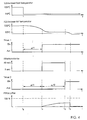
- FIG. 4 shows a total of six related time diagrams, of which the first diagram shows the time course the desired cooling water temperature, the second diagram shows the History of the cooling water actual temperature shows the third diagram the time course of the signal level at the output of Program module Timer 1 shows, the fourth diagram the switching the filter constant of the filter 32 shows the fifth Diagram the signal level profile at the output of the program module Timer 2 shows, and the sixth graph finally shows the effects the settings made with the control program on the PWM ratio for controlling the fan motor shows.
- Starting point of the whole process is the switching of the Cooling water target temperature of a high value, here for example 105 degrees Celsius, to a lower value, here, for example, 95 degrees Celsius. With this switching will be First, the primary control for temperature control in the cooling system of the internal combustion engine active.
- the thermostat 11 of the primary control is switched such that the Cooling water actual temperature begins to fall.
- the power control of the fan remains up switched off at time T1.
- the fan control is enabled. Indeed the fan control via the filter 32, the first works with the time constant of 60 seconds.
- the program module Timer 2 determines. With the program module Timer 2, a time period ⁇ t2 is calculated and determined, after the filter constant of the filter 32 from 60 seconds to 5 Seconds is reset. After that, so from the time T2, the filter operates until the next change in the cooling water setpoint temperature with the time constant of 5 seconds.
- the reset of the time constants the filter has no influence on the pulse width modulation to have.
- the fan motor up to his working point on the new unlocked characteristic be up. Resetting the time constant has
- the advantage that the fan control with a shorter time constant on a change of the operating point can react. That means with a shorter time constant of the filter
- the fan motor can better a walking of the working point follow the fan characteristic.
- the minimum waiting time ⁇ t1 should normally with the primary control the actual cooling water temperature below the threshold for the fan motor has dropped.
- These Threshold is in the embodiment discussed here at 95 degrees Celsius. Is the cooling water temperature not fallen below this threshold, so sets the fan after the minimum waiting time ⁇ t1 has elapsed at time T1 a muted start.
- the damping of the fan start causes the drive signal for the PWM modulation fan asymptotically to operating point on fan characteristic approaches.
- This course is exemplary in the sixth Diagram of Figure 4 shown.
- the start of the fan motor of course, in the diagram for the actual cooling water temperature a faster decrease in the actual cooling water temperature to the new cooling water target temperature of 95 Centigrade. If the actual cooling water temperature reaches the new one Target temperature at time T3 is the fan assist no longer necessary and the fan can be switched off. Turning off the fan is effected in this case the duty cycle for the PWM modulation goes to zero.
Landscapes
- Engineering & Computer Science (AREA)
- Chemical & Material Sciences (AREA)
- Combustion & Propulsion (AREA)
- Mechanical Engineering (AREA)
- General Engineering & Computer Science (AREA)
- Control Of Positive-Displacement Air Blowers (AREA)
- Control Of Direct Current Motors (AREA)
- Control Of Electric Motors In General (AREA)
- Control Of Temperature (AREA)
Abstract
Description
Die Erfindung betrifft ein Verfahren zur Leistungssteuerung eines Lüftermotors sowie ein Steuerungsprogramm, mit dem die Leistungssteuerung des Lüftermotors durchgeführt wird. Verfahren und Steuerungsprogramm sind insbesondere geeignet zur Ansteuerung von Lüftermotoren, wie sie bei Lüftern in Kühlsystemen für Verbrennungsmotoren eingesetzt werden. Das Steuerungsprogramm bestimmt hierbei die Lüfterleistung anhand von Kennlinien des Lüftermotors sowie anhand der Betriebsparameter des Kühlsystems und anhand von vorgegebenen Führungsgrößen, die ein einzuregelndes Temperaturniveau vorgeben. Verfahren und Steuerungsprogramm sind hierbei jedoch in keinster Weise auf Kühlsysteme in Kraftfahrzeugen beschränkt, sondern können immer dann eingesetzt werden, wenn es gilt, mit einem Lüftermotor verschiedene Temperaturniveaus einzuregeln.The invention relates to a method for power control a fan motor and a control program with which the Power control of the fan motor is performed. method and control program are particularly suitable for Control of fan motors, as with fans in cooling systems be used for internal combustion engines. The control program determines the fan power based on Characteristics of the fan motor as well as the operating parameters of the cooling system and on the basis of predetermined reference variables, which specify a temperature level to be regulated. method and control program are here but in none Limited way to cooling systems in motor vehicles, but can always be used, if it applies, with one Fan motor to regulate different temperature levels.
Ein gattungsgemäßes Verfahren und ein gattungsgemäßes Steuerungsprogramm sind aus der deutschen Patentanmeldung DE 197 28 814 A1 bekannt. In einem Kühlsystem für einen Verbrennungsmotor eines Kraftfahrzeuges sollen verschiedene Temperaturniveaus eingestellt werden. Die einzustellenden Temperaturniveaus sind hierbei die Führungsgrößen für eine Lüftersteuerung, die mit einem Steuerungsprogramm die erforderliche Lüfterleistung bestimmt. Die Lüfterleistung wird hierbei bestimmt aus den Betriebsparametern des Kühlsystems, der vorgegebenen Führungsgröße. Sowie aus Kennfeldern und Kennlinien des Lüftermotors. Der Betrieb des Lüfters wird hierbei so lange ausgesetzt, bis das Kühlmittel in dem Kühlsystem eine Mindesttemperatur erreicht und überschritten hat. Hiermit soll sichergestellt werden, dass der Verbrennungsmotor möglichst schnell auf Betriebstemperatur kommt und eine Kühlwirkung des Lüftermotors nicht vorzeitig einsetzen kann. Ist die Lüfterfunktion erst einmal freigegeben, so passt das Steuerungsprogramm die Lüfterleistung an das einzuregelnde Temperaturniveau an. Es sind hierbei insbesondere zwei Temperaturniveaus von 90 Grad Celsius und von 108 Grad Celsius vorgesehen, an die die Lüfterleistung anzupassen ist.A generic method and a generic control program are from the German patent application DE 197 28 814 A1. In a cooling system for one Internal combustion engine of a motor vehicle to be different Temperature levels are set. The to be set Temperature levels are the reference variables for this Fan controller, which with a control program the required Fan power determined. The fan power is determined from the operating parameters of the cooling system, the predetermined reference variable. As well as from maps and Characteristics of the fan motor. The operation of the fan will in this case suspended until the coolant in the cooling system has reached and exceeded a minimum temperature. This is to ensure that the internal combustion engine comes as soon as possible to operating temperature and a Cooling effect of the fan motor can not prematurely use. Once the fan function is enabled, it fits Control program the fan power to be regulated Temperature level. There are in particular two temperature levels of 90 degrees Celsius and 108 degrees Celsius provided, to which the fan power is to be adapted.
Die vorgenannte Leistungssteuerung ist somit ein effizientes Verfahren die als Führungsgrößen vorgegebenen Temperaturniveaus so schnell wie möglich zu erreichen. Nachteile ergeben sich jedoch, wenn von einem hohen Temperaturniveau auf ein niederes Temperaturniveau gewechselt werden soll. Der Wechsel des Temperaturniveaus wird nämlich durch den Wechsel der Führungsgröße für die Leistungssteuerung vorgegeben. Diese Führungsgröße macht hierbei einen Schritt von 108 Grad Celsius auf 95 Grad Celsius. Für die Leistungssteuerung des Lüftermotors bedeutet dies, dass er aufgrund der großen Temperaturdifferenz bei einem Wechsel der Führungsgröße von einem hohen auf einen niederen Wert eine große Temperaturdifferenz zur aktuellen Ist-Temperatur feststellt, die es gilt möglichst schnell auszugleichen. Das bedeutet, dass der Lüftermotor mit maximaler Leistung aufheult. Dies hat zwar den Vorteil, dass das niedere Temperaturniveau so schnell wie möglich erreicht wird, ist aber in der Regel weder erwünscht noch notwendig. Das Aufheulen des Lüftermotors führt daher zu einer Lärmbelästigung und zu einem unnötigen Energieverbrauch. The aforementioned power control is thus an efficient one Process the temperature levels specified as reference variables to reach as soon as possible. Disadvantages arise However, if from a high temperature level to a low temperature level to be changed. The change the temperature level is namely by changing the reference variable specified for the power control. This reference makes a step of 108 degrees Celsius to 95 degrees Celsius. For the power control of the fan motor This means that he is due to the large temperature difference when changing the reference variable from a high one to a low value a large temperature difference to current actual temperature determines it applies as possible compensate quickly. This means that the fan motor with maximum power. While this has the advantage that the low temperature level is reached as quickly as possible is, but is usually neither desired nor necessary. The whine of the fan motor therefore leads to a noise annoyance and to an unnecessary energy consumption.
An dieser Stelle setzt die Erfindung ein. Die Erfindung macht es sich nämlich zur Aufgabe, bei einem Wechsel des einzuregelnden Temperaturniveaus von einem hohen Wert auf einen niederen Wert ein Aufheulen des Lüftermotors zu verhindern.At this point, the invention begins. The invention does it is the task, in the case of a change of the one to be regulated Temperature levels from a high level to a low level Value to prevent a whining of the fan motor.
Diese Aufgabe wird gelöst mit einem Verfahren nach Anspruch 1
und einem Steuerungsprogramm nach Anspruch 11. Vorteilhafte
Ausgestaltungen des erfindungsgemäßen Verfahrens und des erfindungsgemäßen
Steuerungsprogramms sind in den Unteransprüchen
und in der Beschreibung der Ausführungsbeispiele enthalten.This object is achieved by a method according to
Die Lösung gelingt hauptsächlich mit einer Leistungssteuerung, bei der die Lüfterleistung aus den Kennlinien des Lüftermotors, den Betriebsparametern des Kühlsystems sowie den in Form von Temperaturniveaus vorgegebenen Führungsgrößen bestimmt wird. Den verschiedenen einzuregelnden Temperaturniveaus sind hierbei verschiedene Kennlinien für die Ansteuerung des Lüftermotors zugeordnet. Wechselt die Führungsgröße für die Steuerung, so bedeutet das auch einen Wechsel der Kennlinien zur Ansteuerung des Lüftermotors. Um ein Aufheulen des Lüftermotors zu verhindern, wird bei einem Wechsel der Führungsgröße für die Lüftersteuerung der Betrieb des Lüftermotors für eine einstellbare Mindestwartezeit konstant gehalten wird. Während dieser Mindestwartezeit können sich die Betriebsparameter des Kühlsystems gegebenenfalls durch andere vom Lüfter unabhängige Steuerungsmechanismen an die neue Führungsgröße so weit angepasst haben, dass ein Aufheulen des Lüftermotors nicht mehr zu besorgen ist.The solution works mainly with a power control, when the fan power from the characteristics of the fan motor, the operating parameters of the cooling system and the determined in the form of temperature levels predetermined reference variables becomes. The different temperature levels to be regulated Here are different characteristics for the control assigned to the fan motor. Changes the reference variable for the control, this also means a change of Characteristic curves for controlling the fan motor. To a howl the fan motor is prevented when changing the Reference variable for the fan control the operation of the fan motor kept constant for an adjustable minimum waiting time becomes. During this minimum waiting time, the operating parameters may change of the cooling system, if necessary by others control mechanisms independent of the fan to the new reference variable have adjusted so far that a howl of the Fan motor is no longer to get.
In einer vorteilhaften Ausgestaltung der Erfindung wird der Anlauf des Lüftermotors mit einem Filter, das in die Ansteuerung des Lüftermotors zugeschaltet wird, gedämpft. Dadurch wird ein langsames Anlaufen des Lüfters ermöglicht, auch dann, wenn bei einem Wechsel des einzuregelnden Temperaturniveaus große Temperaturdifferenzen zu den aktuellen Ist-Temperaturen des zu kühlenden Systems auftreten. Vorzugsweise hat dieses Filter eine sogenannte PT1-Charakteristik.In an advantageous embodiment of the invention, the Start-up of the fan motor with a filter in the control the fan motor is switched on, damped. Thereby Slow start of the fan is possible, too when, when changing the temperature level to be regulated large temperature differences to the current actual temperatures of the system to be cooled occur. Preferably this filter has a so-called PT1 characteristic.
Weitere vorteilhafte Ausgestaltungen der Erfindung beinhalten die Möglichkeit die Mindestwartezeit bis zum Einsetzen des Lüftermotors und die Art und Weise eines eventuellen notwendigen Lüfteranlaufs gezielt an die Systembedingungen anzupassen. Hierzu kann zum Beispiel die Mindestwartezeit in Abhängigkeit der thermischen Belastung des zu kühlenden Systems verkürzt werden oder es können die Filtercharakteristiken, mit denen das Anlaufen des Lüftermotors beeinflusst wird, gezielt verändert werden, so dass der Lüfter schneller auf größere Leistungen hoch läuft. Mit einer Sensorüberwachung des zu kühlenden Systems und der Umgebungsbedingungen kann die zeitliche Dauer der Wirksamkeit einer angepassten Filtereinstellung reduziert werden, wenn sich die Umgebungsbedingungen zu stark ändern, als dass die ausgewählten Filtereinstellungen noch sinnvoll wären. Hierzu wird zum Beispiel die Mindestwartezeit für das Aussetzen des Lüftermotors in Abhängigkeit des einzuregelnden Temperaturniveaus oder der aktuellen Betriebsparameter eingestellt. Ebenso werden die Filtereinstellungen in Abhängigkeit der aktuellen Betriebsparameter eingestellt.Further advantageous embodiments of the invention include the possibility of the minimum waiting time until the onset of Fan motor and the way of any necessary Fan start-up adapted to the system conditions. For this purpose, for example, the minimum waiting time depending on the thermal load of the system to be cooled be shortened or the filter characteristics, with which the startup of the fan motor is influenced targeted be changed so that the fan faster to larger Achievements goes up. With a sensor monitoring of the the system to be cooled and the ambient conditions can be Duration of the effectiveness of an adjusted filter setting be reduced when the environmental conditions too much change than that the selected filter settings would still be useful. For example, this is the minimum waiting time for the suspension of the fan motor depending on of the temperature level to be regulated or the current one Operating parameters set. Likewise, the filter settings depending on the current operating parameters set.
Die Erfindung ist besonders geeignet für den Einsatz in Kühlsystemen von Verbrennungsmotoren. In diesem Fall sind die maßgeblichen Betriebsparameter, nach denen die Filtereinstellungen und die Mindestwartezeit ausgewählt werden, die aktuell anliegende Motorlast des Verbrennungsmotors sowie die Ansauglufttemperatur des Verbrennungsmotors. The invention is particularly suitable for use in cooling systems of internal combustion engines. In this case, the relevant operating parameters, according to which the filter settings and the minimum waiting time to be selected currently applied engine load of the internal combustion engine and the Intake air temperature of the internal combustion engine.
Im folgenden wird die Erfindung ohne Beschränkung der Allgemeinheit am Beispiel eines Kühlsystems für einen Verbrennungsmotor näher erläutert. Dazu wird auf die folgenden Zeichnungen Bezug genommen. Es zeigen:
- Figur 1:
- einen Vergleich zwischen einer Lüfteransteuerung aus dem Stand der Technik und zwei Beispielen einer Lüfteransteuerung gemäß der Erfindung,
- Figur 2:
- ein typisches Kühlsystem für einen Verbrennungsmotor, bei dem die Temperaturregelung und die Lüfteransteuerung mit einem Steuergerät erfolgen, in dem mit einem Steuergerät die gemäß der Erfindung wichtigsten Einflussgrößen verarbeitet werden,
- Figur 3:
- einen vereinfachten Funktionsrahmen und Signalflussplan für das erfindungsgemäße Verfahren und das erfindungsgemäße Steuerungsprogramm,
- Figur 4:
- eine zeitliche Abfolge der mit dem Signalflussplan
nach
Figur 3 getroffenen Einstellungen und deren zeitlichen Einfluss auf den Lüfter und die Kühlwasser-Ist-Temperatur.
- FIG. 1:
- a comparison between a fan drive of the prior art and two examples of a fan drive according to the invention,
- FIG. 2:
- a typical cooling system for an internal combustion engine, in which the temperature control and the fan control are carried out with a control unit in which are processed with a control device, the most important influencing variables according to the invention,
- FIG. 3:
- a simplified functional framework and signal flow diagram for the method according to the invention and the control program according to the invention,
- FIG. 4:
- a temporal sequence of the settings made with the signal flow plan of Figure 3 and their temporal influence on the fan and the cooling water actual temperature.
Üblicherweise werden Lüftermotoren als Sicherung gegen Überhitzung eines zu kühlenden Systems eingesetzt. Das zu kühlende System hat dabei üblicherweise neben der Lüftersteuerung eine primäre Temperaturregelung. Mit dieser primären Temperaturregelung wird die Temperatur im Kühlsystem bevorzugt geregelt. Insbesondere bei Verbrennungsmotoren werden für die primäre Temperaturregelung Thermostaten eingesetzt, mit denen geschlossene Kühlkreisläufe umgeschaltet werden. Thermostaten arbeiten hierbei wesentlich energieschonender als Lüftermotoren und haben zu dem den Vorteil, dass sie die im System befindliche Energie besser im System belassen. Lüftermotoren haben hierbei den Nachteil, dass sie viel Energie verbrauchen nur zu dem Zweck, Energie aus einem bestehenden System herauszunehmen. Es ist jedoch besser, die Energie im System zu belassen und zu versuchen, daraus möglichst viel Wirkleistung entnehmen zu können. Die Temperaturregelung in einem Kühlsystem erfolgt deshalb vorzugsweise mit einer energieschonenden Primärregelung, während der Lüftermotor und die Lüftersteuerung lediglich als zusätzliche Sicherung eingesetzt werden, wenn mit der Primärregelung eine verlässliche Temperaturregelung nicht mehr eingehalten werden kann. Insbesondere in Kraftfahrzeugen soll deshalb der Lüfter möglichst überhaupt nicht zur Temperaturregelung im Kühlsystem herangezogen werden. Bei bekannten Lüftersteuerungen aus dem Stand der Technik ergeben sich hierbei jedoch dann Probleme, wenn wie eingangs bereits ausgeführt, das Temperaturniveau in einem Kühlsystem von einem hohen Wert auf ein niedrigeres Temperaturniveau abgesenkt werden soll. Diese Probleme werden anhand von Figur 1 anschaulich dargestellt und es wird zugleich die vorteilhafte Wirkungsweise einer erfindungsgemäßen Lüftersteuerung dem Stand der Technik gegenüber gestellt.Usually, fan motors are used as a safeguard against overheating a system to be cooled used. The thing to cool System usually has besides the fan control a primary temperature control. With this primary temperature control the temperature in the cooling system is preferably controlled. In particular, in internal combustion engines are for the primary temperature control thermostats used with those closed cooling circuits are switched. thermostats work much more energy-saving than fan motors and have the advantage of being in the system Keep energy better in the system. fan motors This has the disadvantage that they consume a lot of energy only for the purpose of taking energy out of an existing system. However, it is better to use the energy in the system too leave and try to derive as much active power as possible to be able to remove. The temperature control in a cooling system Therefore, it is preferably done with an energy-saving Primary control, while the fan motor and fan control to be used only as an additional backup, if with the primary control a reliable temperature control can no longer be met. In particular in Motor vehicles should therefore the fan as possible at all not used for temperature control in the cooling system. In known fan controllers from the prior art However, problems arise when, as at the beginning already stated, the temperature level in a cooling system from a high value to a lower temperature level should be lowered. These problems are based on Figure 1 clearly illustrated and it is at the same time the advantageous Operation of a fan control according to the invention compared with the prior art.
In Figur 1 ist das Abtastverhältnis einer Pulsweitenmodulation zur Ansteuerung eines Lüftermotors in Prozent PWM gegenüber der Temperatur im Kühlsystem aufgetragen. Mit dem Kühlsystem sollen zwei verschiedene Temperaturniveaus eingeregelt werden können. Ein Temperaturniveau bei 90 Grad und ein zweites Temperaturniveau bei 105 Grad Celsius. Die Temperaturregelung soll überwiegend mit einer Primärregelung erfolgen. Der Lüfter soll als zusätzliches Sicherheitselement gegen Überhitzung dann einspringen, wenn mit der Primärregelung die vorgegebenen Temperaturniveaus nicht gehalten werden können. Typischerweise wird man dazu für jedes Temperaturniveau einen Schwellwert vorsehen, ab dem der Lüftermotor mit steigender Temperatur mit zunehmender Leistung für mehr Kühlung des Systems sorgt. Im Ausführungsbeispiel der Figur 1 ist für das Temperaturniveau von 90 Grad ein Schwellwert von 95 Grad Celsius und für das Temperaturniveau von 105 Grad Celsius ein Schwellwert von 107 Grad Celsius vorgesehen. Je höher die Ist-Temperatur gegenüber diesem Schwellwert abweicht, desto mehr Kühlleistung wird erforderlich sein, um zu dem ursprünglichen einzuregelnden Temperaturniveau zurückzukommen. Für die PWM Ansteuerung des Lüftermotors ergeben sich hierbei für jedes einzuregelnde Temperaturniveau im einfachsten Fall Lüfterkennlinien und bei komplexen Sachverhalten Temperaturkennfelder aus mehreren Lüfterkennlinien, aus denen zu jeder Ist-Temperatur des Kühlmittels im Kühlsystem ein gewünschtes Ansteuersignal für die Leistungsregulierung des Lüftermotors entnehmbar ist. Im Ausführungsbeispiel der Figur 1 sind das die beiden Kennlinien Khigh, Klow bei einem Wechsel des einzuregelnden Temperaturniveaus von 105 Grad Celsius nach 90 Grad Celsius wird für die Lüftersteuerung im Prinzip auch die Kennlinie von Khigh nach Klow gewechselt. Die Ist-Temperatur des Kühlsystems wird jedoch dem Wechsel der Führungsgröße von 105 Grad Celsius nach 90 Grad Celsius nicht sofort folgen können. Für Lüftersteuerungen aus dem Stand der Technik ergibt sich bei diesem Szenario daher das folgende Problem, dass bei einem Wechsel der Führungsgröße auf 90 Grad Celsius die Lüftersteuerung eine extreme Überhitzung des Kühlsystems feststellen wird und der Lüftermotor am oberen Leistungsende seiner Kennlinie anspringen wird. Der Lüftermotor wird regelrecht aufheulen. In Figur 1 ist der Verlauf des Ansteuerungssignals über die Pulsweitenmodulation des Lüftermotors nach dem Stand der Technik strichpunktiert dargestellt und mit StdT bezeichnet. Man erkennt, dass bei einem Wechsel der Führungsgröße von hoch nach tief der Arbeitspunkt von dem unteren Punkt der Kennlinie Khigh für das obere Temperaturniveau auf einen oberen hohen Punkt der Kennlinie Klow für das untere Temperaturniveau springen wird. Dies gilt es, mit der Erfindung zu verhindern. Erfindungsgemäß wird dies gelöst, in dem die Lüfteransteuerung bei einem Wechsel der Führungsgröße zunächst für eine Mindestzeit ausgesetzt wird, um der Primärregelung die Möglichkeit zu geben, das tiefere Temparaturniveau im Kühlsystem einzustellen. Ist nach Ablauf der Mindestwartezeit das tiefere Temperaturniveau mit der Primärregelung noch nicht erreicht, so kann immer noch ein Aufheulen des Lüftermotors verhindert werden, in dem man dafür Sorge trägt, dass der Lüftermotor nicht sofort mit maximaler Leistung anspringt. Dies erfolgt erfindungsgemäß durch Filter, mit denen man abrupte Lastwechsel am Lüftermotor abschwächt. Dies kann zum Beispiel dadurch erfolgen, dass man das Ansteuersignal für den Lüftermotor zwar aus der Kennlinie des Lüftermotors entnimmt, jedoch damit nicht direkt den Lüftermotor ansteuert, sondern mit einem vorgeschalteten Filter dafür Sorge trägt, dass sich die Lüfterleistung asymptotisch an den Arbeitspunkt auf der Lüfterkennlinie annähert. Während dieser Zeit hat die Primärregelung Gelegenheit eine Temperaturabsenkung zu bewirken, die noch durch den schwach anlaufenden Lüfter unterstützt werden wird. Durch den zeitlich verzögerten Anlauf gegebenenfalls in Kombination mit einem noch zusätzlich gedämpften Anlauf des Lüftermotors ergibt sich mit dem erfindungsgemäßen Verfahren beziehungsweise mit dem erfindungsgemäßen Steuerungsprogramm eher ein Signalverlauf für die Pulsweitenmodulation des Lüftermotors wie er in den Kurven D5 und D60 dargestellt ist. Der Verlauf der Kurve D60 entspricht hierbei einem starkdämpfenden Filter, während der Verlauf der Kurve D5 einem schwachdämpfenden Filter in der Anlaufsteuerung des Lüfters entspricht.In Figure 1, the sampling ratio of a pulse width modulation for controlling a fan motor in percent PWM is plotted against the temperature in the cooling system. The cooling system should be able to adjust two different temperature levels. A temperature level at 90 degrees and a second temperature level at 105 degrees Celsius. The temperature control should be done predominantly with a primary control. The fan should then jump in as an additional safety element against overheating, if the predetermined temperature levels can not be maintained with the primary control. Typically, this will provide a threshold level for each temperature level beyond which the fan motor will provide more cooling to the system as the temperature increases with increasing power. In the exemplary embodiment of FIG. 1, a threshold value of 95 degrees Celsius is provided for the temperature level of 90 degrees and a threshold value of 107 degrees Celsius for the temperature level of 105 degrees Celsius. The higher the actual temperature deviates from this threshold, the more cooling power will be required to return to the original temperature level to be adjusted. For the PWM control of the fan motor arise here for each einzeegelnde temperature level in the simplest case fan characteristics and complex issues temperature maps of several fan characteristics from which a desired drive signal for the power regulation of the fan motor can be removed for each actual temperature of the coolant in the cooling system. In the embodiment of Figure 1 are the two curves K high , K low at a change of einzuregelnden temperature levels of 105 degrees Celsius to 90 degrees Celsius for the fan control in principle, the characteristic of K high to K low is changed. However, the actual temperature of the cooling system will not be able to immediately follow the change in the reference variable from 105 degrees Celsius to 90 degrees Celsius. For fan controls of the prior art, therefore, the following problem arises in this scenario that when changing the reference variable to 90 degrees Celsius, the fan control will notice extreme overheating of the cooling system and the fan motor will start at the upper end of its performance curve. The fan motor will literally howl. In Figure 1, the course of the drive signal via the pulse width modulation of the fan motor according to the prior art is shown in phantom and designated StdT. It can be seen that when the reference variable changes from high to low, the operating point will jump from the lower point of the characteristic K high for the upper temperature level to an upper high point of the characteristic K low for the lower temperature level. This is to be avoided with the invention. This is achieved according to the invention, in which the fan control is initially exposed to a change in the reference variable for a minimum time in order to give the primary control the opportunity to set the lower temperature level in the cooling system. If, after the minimum waiting time, the lower temperature level has not yet been reached with the primary control, it is still possible to prevent the fan motor from howling, by ensuring that the fan motor does not immediately start up at maximum power. This is done according to the invention by filters, which mitigates abrupt load changes on the fan motor. This can be done, for example, by taking the control signal for the fan motor from the characteristic of the fan motor, but not directly the fan motor drives, but with an upstream filter ensures that the fan power asymptotically to the operating point on the fan characteristic approaches. During this time, the primary control has the opportunity to cause a temperature drop, which will still be supported by the low starting fan. Due to the time-delayed startup, possibly in combination with an additionally damped startup of the fan motor, the method according to the invention or the control program according to the invention rather results in a signal curve for the pulse width modulation of the fan motor as shown in curves D5 and D60. The course of the curve D60 corresponds to a strong damping filter, while the course of the curve D5 corresponds to a low attenuation filter in the startup control of the fan.
Die erfindungsgemäße Lüftersteuerung ist hierbei insbesondere
geeignet für den Einsatz in einem Kühlsystem für einen
Verbrennungsmotor. Figur 2 zeigt schematisch ein typisches
Kühlsystem für einen Sechszylinder-Verbrennungsmotor 1. Neben
dem Verbrennungsmotor sind in das Kühlsystem ein Fahrzeugkühler
2 und ein Heizungswärmetauscher 3 integriert. Die Kühlleistung
des Fahrzeugkühlers kann mit einem elektrisch angetriebenen
Lüfter 4 beeinflusst werden. Zur Regulierung der
Lüfterleistung wird der elektrische Motor des Lüfters mit einem
Steuergerät 5 geregelt. Aus dem Fahrzeugkühler wird mittels
der Vorlaufleitung 6 gekühltes Kühlmittel entnommen und
mit der Kühlmittelpumpe 7 in die Kühlleitungen 8 zur Speisung
der nicht näher dargestellten Kühlkanäle für die Verbrennungszylinder
9 eingespeist. Von den Verbrennungszylindern 9
wird das erhitzte Kühlmittel über Rückleitungen 10 zu einem
Dreiwegethermostaten 11 geführt. Je nach Stellung der Ventile
in dem Dreiwegethermostaten 11 gelangt das Kühlmittel aus dem
Verbrennungsmotor über den Kühlerrücklauf 12 wieder zurück in
den Fahrzeugkühler oder über den Kühlerkurzschluss 13 und die
Kühlmittelpumpe 7 wieder zurück in die Kühlleitungen 8 des
Verbrennungsmotors.The fan control according to the invention is in this case in particular
suitable for use in a cooling system for one
Combustion engine. Figure 2 shows schematically a typical
Cooling system for a six-cylinder
Je nach Stellung der Ventile im Dreiwegethermostaten 11 kann
das Kühlsystem hierbei in an sich bekannter Weise im Kurzschlussbetrieb,
im Mischbetrieb oder im großen Kühlkreislauf
gefahren werden. Der Heizungswärmetauscher 3 ist über ein
temperaturgesteuertes Absperrventil 14 an den Hochtemperaturzweig
des Kühlsystems im Verbrennungsmotor angeschlossen. Der
Durchsatz nach Öffnen des Absperrventils 14 durch den Heizungswärmetauscher
kann zur Regulierung der Heizleistung mit
einer zusätzlichen Kühlmittelpumpe 15 und einem getakteten
Absperrventil 16 reguliert werden.Depending on the position of the valves in
Die Ansteuerung der Betätigungselemente an den Ventilen des
Dreiwegethermostaten 11 wird hierbei von dem Steuergerät 5
eingestellt. In dem Steuergerät ist ein logisches Bauelement
Logik in Form einer mikroelektronischen Recheneinheit enthalten.
Vorzugsweise wird das Steuergerät durch das Steuergerät
der Motorelektronik gebildet oder ist ein Bestandteil im
Steuergerät der Motorelektronik. Mit dem Steuergerät 5 wird
hierbei der Dreiwegethermostat 11 sowie der Lüftermotor 4 angesteuert.
Die Ansteuerung des Heizelementes in dem Dreiwegethermostaten
11 erfolgt hierbei in an sich bekannter Weise.
Der Dreiwegethermostat 11 ist hierbei das Stellelement für
die eingangs angesprochene Primärregelung, die ebenfalls als
Steuerprogramm für die Ansteuerung des Heizelements in dem
Dreiwegethermostaten 11 in dem Steuergerät 5 implementiert
ist. Durch geeignete Ansteuerung des Dreiwegethermostaten 11
können in dem Kühlsystem für den Verbrennungsmotor insbesondere
3 verschiedene Temperaturniveaus von 80 Grad Celsius, 90
Grad Celsius, 105 Grad Celsius eingestellt und geregelt werden.
Die Einstellung der Temperaturniveaus erfolgt hierbei
überwiegend lastgeregelt. Das heißt, aus den Betriebsarten
des Verbrennungsmotors, die üblicherweise in der Motorelektronik
eines modernen Verbrennungsmotors in Form von digitalen
Signalwerten abgreifbar sind, wird aus den Anforderungen an
den Motor die zu der aktuellen Anforderung geeignete Temperatur
im Kühlsystem eingestellt. Wichtigste Einflussgröße ist
hierbei die Motorlast, die insbesondere aus der Motordrehzahl,
der angesaugten Luftmenge oder der in die Verbrennungszylinder
eingespritzten Kraftstoffmenge bestimmt wird. Gelingt
eine zufriedenstellende Temperaturregelung mit dem
Dreiwegethermostaten 11 alleine nicht mehr, so kann für eine
zusätzliche Kühlung der Lüfter eingesetzt werden. Die Ansteuerung
des Lüftermotors 4 erfolgt hierbei ebenfalls mit dem
Steuergerät 5. Üblicherweise werden die Lüftermotoren in ihrer
Leistung mit einer Pulsweitenmodulation geregelt. Hierzu
wird von einem Steuerprogramm aus den Betriebsparametern des
Kühlsystems die erforderliche Kühlleistung berechnet und bei
Kenntnis der aktuell erforderlichen Kühlleistung aus den Lüfterkennlinien
das Abtastverhältnis der Pulsweitenmodulation
ermittelt, mit dem die geforderte Kühlleistung erbracht werden
kann. Die wichtigsten Einflussgrößen für die Ermittlung
der geeigneten Lüfterleistung sind hierbei die aktuell anliegende
Motorlast, die Kühlwasser-Soll-Temperatur, die Kühlwasser-Ist-Temperatur,
die Ansaugluftemperatur sowie die Lüfterkennlinien.
Sollen verschiedene Temperaturniveaus mit dem
Kühlsystem gefahren werden, so können für die verschiedenen
Temperaturniveaus verschiedene Lüfterkennlinien Khigh, Klow zum
Einsatz kommen.The control of the actuators on the valves of the
Erfindungsgemäß wird nun das Steuerungsprogramm für die Ansteuerung des Lüftermotors dahingehend erweitert, dass bei einer Absenkung des Temperaturniveaus in dem Kühlsystem ein Anlaufen des Lüftermotors zumindest für eine Mindestwartezeit unterbunden wird und falls nach der Mindestwartezeit noch ein Lüfteranlauf notwendig ist, dieser Lüfteranlauf derart abgedämpft wird, dass der Arbeitspunkt der Lüftersteuerung auf der Lüfterkennlinie asymptotisch angefahren werden kann. Dies gelingt erfindungsgemäß mit einem Steuerungsprogramm, wie es im folgenden in Zusammenhang mit der Figur 3 näher beschrieben wird.According to the invention, the control program for the control the fan motor extended so that at a lowering of the temperature level in the cooling system Starting the fan motor at least for a minimum waiting time is stopped and if after the minimum waiting still another Fan startup is necessary, this fan start so damped is that the operating point of the fan control on the fan characteristic can be approached asymptotically. This succeeds according to the invention with a control program, as it in the following in connection with the figure 3 described in more detail becomes.
Figur 3 zeigt den Funktionsrahmen und den Signalflussplan des
erfindungsgemäßen Steuerungsprogramms. Eingangsseitig werden
von dem Steuerungsprogramm Signalwerte verarbeitet, die vorzugsweise
aus der Motorsteuerung und hier aus dem Motorsteuergerät
entnommen werden. Es sind dies die Kühlwasser-Soll-Temperatur,
die Kühlwasser-Ist-Temperatur, die Ansauglufttemperatur,
sowie eine Kenngröße für die Motorlast, mit der der
Verbrennungsmotor aktuell betrieben wird. Aus der vom Motormanagement
vorgegebenen Kühlwasser-Soll-Temperatur wird mit
einem Programmmodul 31 eine zugehörige Lüfterkennlinie oder
ein zugehöriges Lüfterkennfeld ausgewählt und in einen Arbeitsspeicher
eingelesen. Durch Überwachung der Kühlwasser-Ist-Temperatur
kann mit dem Programmmodul 31 in dem aktuellen
Kennfeld des Lüfters oder der aktuellen Kennlinie der Arbeitspunkt
gefunden werden, mit dem der Lüftermotor zu
betreiben ist. Ergebnis dieses Verarbeitungsprozesses ist ein
Ansteuersignal an die Leistungselektronik des Lüftermotors.
Vorzugsweise ist dieses Ansteuersignal ein Pulsweitenmodulationsverhältnis,
mit dem die Leistungssteuerung des Lüftermotors
eingestellt wird.FIG. 3 shows the functional framework and the signal flow plan of the
Control program according to the invention. Becoming input side
processed by the control program signal values, preferably
from the engine control and here from the engine control unit
be removed. These are the cooling water target temperature,
the actual cooling water temperature, the intake air temperature,
and a characteristic for the engine load, with the
Internal combustion engine is currently operated. From the engine management
specified cooling water target temperature is with
a
Ändert sich die vom Motormanagement vorgegebene Kühlwasser-Soll-Temperatur,
so wird mit dem Programmmodul 31 zur Auswahl
einer neuen Lüfterkennlinie der vorbeschriebene Prozess für
die neue Kühlwasser-Soll-Temperatur durchgeführt. Das Programmmodul
31 schaltet gewissermaßen von einer Kennlinie Khigh
für die hohe Kühlwasser-Soll-Temperatur auf eine Kennlinie
Klow für eine niedrigere Kühlwasser-Soll-Temperatur um. Weiterhin
wird permanent die Kühlwasser-Ist-Temperatur überwacht.
So dass auch auf der neuen Lüfterkennlinie Klow ein Arbeitspunkt
für den Lüftermotor gefunden und eingestellt werden
kann. Der Wechsel der Kühlwasser-Soll-Temperatur und der
Wechsel der zugehörigen Kennlinie wird programmtechnisch mit
einem Unterprogramm 33 ausgewertet. Es wird geprüft, ob sich
die Kühlwasser-Soll-Temperatur von einer hohen Temperaturvorgabe
auf eine niedrigere Temperaturvorgabe geändert hat. Ist
dies der Fall, so wird ein weiteres Programmmodul, mit Timer
1 bezeichnet, aktiviert. In Figur 3 ist der Aktivierungsschritt
symbolisch mit der Wahrheitsvariablen true dargestellt.
Mit dem Programmmodul Timer 1 wird in Abhängigkeit
weiterer Betriebsparameter des zu kühlenden Systems eine Mindestwartezeit
Δt1 berechnet und bestimmt, während derer der
Betriebpunkt des Lüftermotors beibehalten wird. Das Aussetzen
von Änderungen der Leistungssteuerung des Lüftermotors erfolgt
zweckmäßigerweise derart, dass mit dem Programmmodul
Timer 1 ein Schaltvorgang 34 angesprochen wird, mit dem eine
Änderungen der Leistungssteuerung des Lüftermotors unterbunden
werden kann. Wie lange die Leistungssteuerung des Lüftermotor
auszusetzen ist, bestimmt sich aus den aktuellen Betriebsparametern
des Verbrennungsmotors und des Kühlsystems.
Vorgesehen sind Mindestwartezeiten von 5 Sekunden, 30 Sekunden,
60 Sekunden, in Figur 3 symbolisch als Eingabegrößen 5,
30 und 60 zu dem Programmmodul Timer 1 dargestellt. Wichtigste
Einflussgrößen für die Bestimmung der Mindestwartezeit
sind die aktuell anliegende Motorlast, die aktuell anliegende
Ansauglufttemperatur des Verbrennungsmotors, die aktuelle
Kühlwasser-Ist-Temperatur und die Größe des Temperatursprungs
bei der vorgegebenen Kühlwasser-Soll-Temperatur. In modernen
Verbrennungsmotoren werden je nach Leistungsanforderung an
den Verbrennungsmotor von dem Motormanagement bis zu drei
verschiedene Kühlwasser-Soll-Temperaturen an das Kühlsystem
des Verbrennungsmotors vorgegeben und eingestellt. Typische
Temperaturniveaus für die Kühlwasser-Soll-Temperaturen sind
hierbei 80 Grad Celsius, 90 Grad Celsius und 105 Grad Celsius.
Bei einem Wechsel der Kühlwasser-Soll-Temperatur von 105
Grad Celsius auf 80 Grad Celsius ist hierbei eine Mindestwartezeit
von 60 Sekunden vorgesehen, bei einem Wechsel der
Kühlwasser-Soll-Temperatur von 105 Grad Celsius auf 90 Grad
Celsius ist eine Mindestwartezeit von 30 Sekunden vorgesehen.
Die vorgenannten Mindestwartezeiten können abgebrochen werden,
wenn dies zum Schutz gegen Überhitzung des Kühlsystems
oder des Verbrennungsmotors notwendig ist. In allen Fällen
ist jedoch eine Mindestwartezeit von 5 Sekunden vorgesehen.
Die Möglichkeit die Mindestwartezeiten bei der Gefahr der Überlastung
abzubrechen, stellt eine Schutzfunktion für den
Verbrennungsmotor dar. Diese Schutzfunktion wird immer dann
aktiviert, wenn die Kühlwasser-Ist-Temperatur einen kritischen
Wert von zum Beispiel von 107 Grad Celsius übersteigt,
wenn die Ansauglufttemperatur des Verbrennungsmotors über 50
Grad Celsius liegt, oder wenn die Motorlast des Verbrennungsmotors,
bestimmt aus der Drehzahl des Verbrennungsmotors und
dem Füllungsgrad der Verbrennungszylinder, über 90 Prozent
der Maximallast des Verbrennungsmotors liegt. In diesen Fällen
wird mit dem Timer 1 die Mindestwartezeit auf 5 Sekunden
verkürzt, beziehungsweise, falls die Überlast des Verbrennungsmotors
während der beiden längeren Wartezeiten von 60
Sekunden und 30 Sekunden auftritt, die längeren Mindestwartezeiten
abgebrochen. Die Berechnung der aktuellen Motorlast
und die Bestimmung der aktuellen Ansauglufttemperatur wird
hierbei ebenfalls vom Motormanagement respektive dem Motorsteuergerät
bestimmt und vom erfindungsgemäßen Steuerprogramm
weiterverarbeitet. Im einfachsten Fall enthält für diese
Weiterverarbeitung das Programmmodul Timer 1 Vergleichsoperationen,
mit denen überprüft wird, ob die Betriebsparameter
des Kühlsystems und des Verbrennungsmotors in den jeweils
als zulässig definierten Bereichen liegen oder nicht.If the cooling-water setpoint temperature predefined by the engine management system changes, then the above-described process for the new cooling-water setpoint temperature is carried out with the
Nach Ablauf der vom Timer 1 bestimmten Mindestwartezeit wird
die Low-Kennlinie Klow, beziehungsweise genauer das auf Grundlage
der Low-Kennlinie berechnete Ansteuersignal an den Lüftermotor,
freigegeben. Die High-Kennlinie Khigh wird nicht geschaltet
und bleibt ständig aktiv. Die Freigabe der Kennlinie
ist in Figur 3 symbolisch mit dem Schaltvorgang 34 dargestellt,
der als Schalter ausgebildet sein kann oder bevorzugter
Weise mit einer programmtechnischen Schaltoperation realisiert
ist. Ist nach Umschalten der Kühlwasser-Soll-Temperatur
und nach Ablauf der Mindestwartezeit die Temperaturdifferenz
zwischen neuer Kühlwasser-Soll-Temperatur und
aktueller Kühlwasser-Ist-Temperatur so groß, dass noch ein
Lüftereinsatz notwendig wird, so wird der nun mögliche Lüfteranlauf
mit dem erfindungsgemäßen Steuerungsprogramm abgedämpft.
Damit wird ein Aufheulen des Lüfters verhindert. Ob
ein Lüfteranlauf notwendig ist, wird mit dem Programmmodul 31
in an sich bekannter Weise berechnet, in dem geprüft wird, ob
die Abweichung der Kühlwasser-Ist-Tempartur größer als tolerierbar
ist. After the minimum waiting time determined by the
Die Dämpfung des Lüfteranlaufs erfolgt mit einem einstellbaren
digitalen Filter 32, mit dem das Ansteuersignal an die
Elektronik des Lüftermotors gefiltert wird. Das Filter sorgt
dafür, dass das filtereingangsseitig anliegende Ansteuersignal
auf den Filterausgang mit einer asymptotisch auf den Eingangswert
hochlaufenden Filterkennlinie übertragen wird. Vorzugsweise
handelt es sich bei dem Filter um ein Filter mit
sogenannter PT1-Charakteristik. Diese Filter zeichnen sich
durch eine Filterkennlinie mit exponentiellem Verlauf aus,
wobei die Zeitkonstante der Exponentialfunktion angibt, nach
welcher Zeit das Ausgangssignal 66 Prozent des Wertes des
Eingangssignal erreicht hat. Durch Wahl der Zeitkonstanten
der Exponentialfunktion können diese Filter in ihrer Wirkung
angepasst und eingestellt werden. Dies macht sich auch die
Erfindung zunutze, in dem mit einem Unterprogramm 35 die Filterkonstante
des Filters 32 austauschbar ausgeführt ist. Vorgesehen
sind hierbei eine Zeitkonstante von 5 Sekunden und
eine Zeitkonstante von 60 Sekunden. Die Umschaltung der Zeitkonstanten
des Filters wird von dem Programmmodul Timer 2 getriggert,
indem ein Auswahlvorgang 35 aktiviert wird. Der
Auswahlvorgang ist in Figur 3 als Schaltvorgang dargestellt,
wird jedoch in der Regel als programmtechnischer Auswahlprozess
realisiert sein.The damping of the fan startup is done with an adjustable
Mit dem Programmmodul Timer 2 wird die Dauer der Filtereinstellungen
des vorgenannten Filters 32 eingestellt. Das Programmmodul
Timer 2 dient hierbei hauptsächlich der Rücksetzung
der Zeitkonstanten des Filters 32 von einer hohen Zeitkonstante
auf eine niedrigere Zeitkonstante. In dem Ausführungsbeispiel
der Figur 3 sind dies die beiden Zeitkonstanten
5 Sekunden und 60 Sekunden zur Beeinflussung der Zeitcharakteristik
des Filters 32. Der Timer 2 setzt hierbei zeitlich
auf das Ausgangssignal des Programmmoduls Timer 1 auf. Genauer
wird das Ende der Mindestwartezeit Δt1 als zeitlicher Anknüpfungspunkt
für die Aktivierung des Programmmoduls Timer 2
genommen. Mit dem Beginn der Mindestwartezeit Δt1 beziehungsweise
mit dem Freischalten der Kennlinie Klow wird die Zeitkonstante
des Filters 32 regelmäßig auf ihren hohen Wert von
beispielsweise 60 Sekunden gesetzt. Diese Einstellung bleibt
so lange aktiv, bis mit einem Umschaltsignal aus dem Programmmodul
Timer 2 die Filterkonstante wieder auf den niedrigeren
Wert von beispielsweise 5 Sekunden gesetzt wird. Dieses
Rücksetzsignal wird von dem Programmmodul Timer 2 nach Ablauf
einer Zeitdauer Δt2, die sich zeitlich an das Ende der Mindestwartezeit
Δt1 anschließt, gegeben. Diese add-on-Zeit beträgt
zum Beispiel regelmäßig 60 Sekunden. Liegen keine besonderen
Umstände vor, so bleiben die Filtereinstellungen des
Filters 32 nach Ablauf der Mindestwartezeit Δt1 für die Zeitspanne
Δt2 von zum Beispiel 60 Sekunden aktiv.With the
Besondere Umstände liegen jedoch dann vor, wenn die Gefahr
einer Überhitzung aufgrund zu hoher Dämpfungswirkung des Filters
32 besteht. Diese Gefahr kann dann bestehen, wenn die
Filtereinstellungen lediglich einen langsamen Lüfteranlauf
zulassen. Deshalb ist mit dem Programmmodul Timer 2 eine
Schutzfunktion realisiert, mit der die Zeitdauer der Filtereinstellungen
verkürzt werden kann. Hierzu wird mit dem Programmmodul
Timer 2 ebenfalls die Ansauglufttemperatur des
Verbrennungsmotors sowie die aktuelle Motorlast des Verbrennungsmotors
durch Überwachung der entsprechenden Kenngrößen
aus dem Motorsteuergerät mitgelesen. Übersteigt die Ansauglufttemperatur
den Wert von 50 Grad Celsius oder liegt die
Motorlast über einem Wert von 90 Prozent der maximalen möglichen
Motorlast, so wird die Zeitkonstante des Filters 32 sofort
auf den niedrigeren Wert von 5 Sekunden zurückgesetzt.
Dadurch kann im Falle der Gefahr einer Überlastung der Lüfter
schneller zu seiner Maximalleistung hochlaufen. Der Lüfter
wird nämlich bei einer kleineren Zeitkonstante des Filters 32
schneller wirksam.However, special circumstances exist when the danger
Overheating due to excessive damping effect of the
Das Zusammenspiel der einzelnen Programmmodule, wie in Figur 3 beschrieben, und die Wirkungsweise des erfindungsgemäßen Steuerprogramms wird im folgenden nochmals anhand von Figur 4 erläutert.The interaction of the individual program modules, as shown in FIG 3 described, and the operation of the invention Control program will be described again below with reference to FIG. 4 explained.
Figur 4 zeigt insgesamt sechs aufeinander bezogene Zeitdiagramme,
von denen das erste Diagramm den zeitlichen Verlauf
der Kühlwasser-Soll-Temperatur zeigt, das zweite Diagramm den
Verlauf der Kühlwasser-Ist-Temperatur zeigt, das dritte Diagramm
den zeitlichen Verlauf des Signalpegels am Ausgang des
Programmmoduls Timer 1 zeigt, das vierte Diagramm das Umschalten
der Filterkonstante des Filters 32 zeigt, das fünfte
Diagramm den Signalpegelverlauf am Ausgang des Programmmoduls
Timer 2 zeigt, und das sechste Diagramm schließlich die Auswirkungen
der mit dem Steuerprogramm getroffenen Einstellungen
auf das PWM-Verhältnis zur Ansteuerung des Lüftermotors
zeigt. Startpunkt des ganzen Prozesses ist das Umschalten der
Kühlwasser-Soll-Temperatur von einem hohen Wert, hier beispielsweise
105 Grad Celsius, auf einen niedrigeren Wert,
hier zum Beispiel 95 Grad Celsius. Mit diesem Umschalten wird
zunächst die Primärregelung zur Temperaturregelung im Kühlsystem
des Verbrennungsmotors aktiv. Das heißt der Thermostat
11 der Primärregelung wird derart geschaltet, dass die
Kühlwasser-Ist-Temperatur zu fallen beginnt. Für eine Zeitdauer
Δt1, die vom Programmmodul Timer 1 berechnet und eingestellt
wird, bleibt die Leistungssteuerung des Lüfters bis
zum Zeitpunkt T1 ausgeschaltet. Nach Ablauf der Mindestwartezeit
Δt1 wird die Lüfteransteuerung freigegeben. Allerdings
erfolgt die Lüfteransteuerung über den Filter 32, der zunächst
mit der Zeitkonstanten von 60 Sekunden arbeitet. Wie
lange die Filtereinstellungen erhalten bleiben, wird durch
das Programmmodul Timer 2 bestimmt. Mit dem Programmmodul Timer
2 wird eine Zeitdauer Δt2 berechnet und bestimmt, nach
der die Filterkonstante des Filters 32 von 60 Sekunden auf 5
Sekunden zurückgesetzt wird. Danach, also ab dem Zeitpunkt
T2, arbeitet das Filter bis zum nächsten Wechsel der Kühlwasser-Soll-Temperatur
mit der Zeitkonstante von 5 Sekunden. In
der Mehrzahl der Fälle wird das Rücksetzen der Zeitkonstanten
des Filters keinen Einfluss mehr auf die Pulsweitenmodulation
haben. In der Mehrzahl der Fälle wird nämlich nach Ablauf der
Zeitdauer Δt2 also bis zum Zeitpunkt T2 der Lüftermotor bis
zu seinem Arbeitspunkt auf der neuen freigeschalteten Kennlinie
hochgelaufen sein. Das Rücksetzen der Zeitkonstante hat
allerdings den Vorteil, dass die Lüftersteuerung mit einer
kürzeren Zeitkonstante auf eine Änderung des Arbeitspunktes
reagieren kann. Das heißt mit kürzerer Zeitkonstante des Filters
kann der Lüftermotor besser einem Wandern des Arbeitspunktes
auf der Lüfterkennlinie folgen.FIG. 4 shows a total of six related time diagrams,
of which the first diagram shows the time course
the desired cooling water temperature, the second diagram shows the
History of the cooling water actual temperature shows the third diagram
the time course of the signal level at the output of
Nach Ende der Mindestwartezeit Δt1 sollte im Regelfall mit der Primärregelung die Kühlwasser-Ist-Temperatur unterhalb der Einsatzschwelle für den Lüftermotor gefallen sein. Diese Einsatzschwelle liegt in dem hier diskutierten Ausführungsbeispiel bei 95 Grad Celsius. Ist die Kühlwassertemperatur nicht unter diese Einsatzschwelle gefallen, so setzt der Lüfter nach Ablauf der Mindestwartezeit Δt1 zum Zeitpunkt T1 mit einem gedämpften Anlauf ein. Die Dämpfung des Lüfteranlaufs bewirkt, dass sich das Ansteuersignal für die PWM-Modulation des Lüfters asymptotisch dem Arbeitspunkt auf der Lüfterkennlinie nähert. Dieser Verlauf ist exemplarisch im sechsten Diagramm der Figur 4 dargestellt. Der Anlauf des Lüftermotors bewirkt natürlich im Diagramm für die Kühlwasser-Ist-Temperatur ein schnelleres Absinken der Kühlwasser-Ist-Temperatur auf die neue Kühlwasser-Soll-Temperatur von 95 Grad Celsius. Erreicht die Kühlwasser-Ist-Temperatur die neue Soll-Temperatur zum Zeitpunkt T3 ist die Lüfterunterstützung nicht mehr notwendig und der Lüfter kann ausgeschaltet werden. Das Ausschalten des Lüfters wird hierbei bewirkt in dem das Tastverhältnis für die PWM-Modulation auf Null geht.After the minimum waiting time Δt1 should normally with the primary control the actual cooling water temperature below the threshold for the fan motor has dropped. These Threshold is in the embodiment discussed here at 95 degrees Celsius. Is the cooling water temperature not fallen below this threshold, so sets the fan after the minimum waiting time Δt1 has elapsed at time T1 a muted start. The damping of the fan start causes the drive signal for the PWM modulation fan asymptotically to operating point on fan characteristic approaches. This course is exemplary in the sixth Diagram of Figure 4 shown. The start of the fan motor of course, in the diagram for the actual cooling water temperature a faster decrease in the actual cooling water temperature to the new cooling water target temperature of 95 Centigrade. If the actual cooling water temperature reaches the new one Target temperature at time T3 is the fan assist no longer necessary and the fan can be switched off. Turning off the fan is effected in this case the duty cycle for the PWM modulation goes to zero.
Claims (19)
dadurch gekennzeichnet, dass jedem Temperaturniveau eine Kennlinie (Khigh, Klow) zur Leistungssteuerung zugeordnet ist und das bei einem Wechsel der Führungsgröße die Lüftersteuerung für eine einstellbare Mindestwartezeit (Δt1) lang den Betrieb des Lüftermotors (4) konstant hält.Method for power control of a fan motor (4), in which the power control is performed with a fan control, the fan power based on several characteristics (K high , K low ) of the fan motor (4) and the operating parameters of the cooling system (2,6,7,8, 10, 11, 12) and the operating parameters of the cooling system include a plurality of selectable temperature levels as a power control reference.
characterized in that each temperature level is associated with a characteristic curve (K high , K low ) for power control and the fan control for an adjustable minimum waiting time (.DELTA.t1) long keeps the operation of the fan motor (4) constant when changing the reference variable.
dadurch gekennzeichnet, dass bei einem Wechsel der Führungsgröße die Lüftersteuerung die Kennlinie (Khigh, Klow) wechselt.Method according to claim 1,
characterized in that when changing the reference variable, the fan control, the characteristic (K high , K low ) changes.
dadurch gekennzeichnet, dass bei einem Wechsel der Kennlinie (Khigh, Klow) ein Filter (32), insbesondere ein dämpfendes Filter, in die Ansteuerung des Lüftermotors zugeschaltet wird.Method according to claim 2,
characterized in that when changing the characteristic (K high , K low ), a filter (32), in particular a damping filter, is switched into the control of the fan motor.
dadurch gekennzeichnet, dass das Filter (32) PT1-Charakteristik hat.Method according to claim 3,
characterized in that the filter (32) has PT1 characteristic.
dadurch gekennzeichnet,
mit einem Programmmodul (TIMER1) die Mindestwartezeit (Δt1) veränderbar und einstellbar ist.Method according to one of claims 1 to 4
characterized
With a program module (TIMER1), the minimum waiting time (Δt1) can be changed and set.
dadurch gekennzeichnet, dass mit einem zweiten Programmmodul (TIMER2) die Charakteristik des Filters veränderbar und einstellbar ist.Method according to one of claims 3 to 5
characterized in that with a second program module (TIMER2) the characteristic of the filter is variable and adjustable.
dadurch gekennzeichnet, dass mit dem zweiten Programmmodul (TIMER2) und mit einer Auswahl (35) die Zeitkonstanten des Filters und die Dauer (Δt2) der Filtereinstellungen einstellbar sind.Method according to claim 6,
characterized in that with the second program module (TIMER2) and with a selection (35) the time constants of the filter and the duration (.DELTA.t2) of the filter settings are adjustable.
dadurch gekennzeichnet, dass die Mindestwartezeit (Δt1) in Abhängigkeit des einzuregelnden Temperaturniveaus oder der aktuellen Betriebsparameter eingestellt wird.Method according to one of claims 1 to 7
characterized in that the minimum waiting time (Δt1) is set as a function of the temperature level to be regulated or the current operating parameters.
dadurch gekennzeichnet, dass die Zeitkonstante des Filters in Abhängigkeit der aktuellen Betriebsparameter eingestellt wird. Method according to one of claims 3 to 8
characterized in that the time constant of the filter is set as a function of the current operating parameters.
dadurch gekennzeichnet, dass die Betriebsparameter insbesondere Motorlast und Ansauglufttemperatur eines Verbrennungsmotors (1) sind.Method according to claim 8 or 9,
characterized in that the operating parameters are in particular engine load and intake air temperature of an internal combustion engine (1).
dadurch gekennzeichnet, dass das Steuerungsprogramm ein Programmmodul (31) zur Auswahl und zum Wechsel der Kennlinie des Lüftermotors (4) hat, wobei die auszuwählende Kennlinie (Khigh, Klow) anhand einer an den Schnittstellen vorgegebenen Führungsgröße ausgewählt wird,
und dass das Steuerungsprogramm ein Programmmodul (TIMER1) hat, mit dem bei einem Wechsel der Kennlinie (Khigh, Klow) der Betrieb des Lüftermotors (4) für eine Mindestwartezeit (Δt1) konstant gehalten wird.Control program for power control of a fan motor (4) with the fan power based on several characteristics (K high , K low ) of the fan motor, based on current operating parameters of the system to be cooled (2,6,7,8,10,11,12) and is adjusted in the form of temperature levels using
characterized in that the control program has a program module (31) for selecting and changing the characteristic curve of the fan motor (4), wherein the characteristic curve to be selected (K high , K low ) is selected on the basis of a reference variable predetermined at the interfaces,
and that the control program has a program module (TIMER1), with which the operation of the fan motor (4) for a minimum waiting time (.DELTA.t1) is kept constant when changing the characteristic (K high , K low ).
dadurch gekennzeichnet, dass das Steuerprogramm ein digitales Filter (32) enthält, das bei einem Wechsel der Kennlinie in den Programmablauf zur Ansteuerung des Lüftermotors miteinbezogen wird.Control program according to claim 11,
characterized in that the control program includes a digital filter (32), which is included in a change of the characteristic in the program sequence for driving the fan motor.
dadurch gekennzeichnet, dass die Mindestwartezeit (Δt1) mit einem Programmmodul (TIMER1) veränderbar und einstellbar ist. Control program according to Claim 11 or 12,
characterized in that the minimum waiting time (Δt1) with a program module (TIMER1) is variable and adjustable.
dadurch gekennzeichnet, dass mit dem Programmmodul (TIMER2) und einer Auswahl (35) die Charakteristik des digitalen Filters (31) veränderbar und einstellbar ist.Control program according to one of claims 11 to 13,
characterized in that with the program module (TIMER2) and a selection (35), the characteristic of the digital filter (31) is variable and adjustable.
dadurch gekennzeichnet, dass mit dem Programmmodul (TIMER2) und der Auswahl (35) die Zeitkonstanten des Filters und die Dauer (Δt2) der Filtereinstellungen einstellbar sind.Control program according to claim 14
characterized in that with the program module (TIMER2) and the selection (35) the time constants of the filter and the duration (.DELTA.t2) of the filter settings are adjustable.
dadurch gekennzeichnet, dass mit einem Programmmodul (TIMER1) die Mindestwartezeit (Δt1) in Abhängigkeit der Führungsgröße oder der aktuellen Betriebsparameter ausgewählt wird.Control program according to one of claims 11 to 15,
characterized in that with a program module (TIMER1) the minimum waiting time (Δt1) is selected as a function of the reference variable or the current operating parameters.
dadurch gekennzeichnet, dass die Charakteristik des digitalen Filters (31) in Abhängigkeit der aktuellen Betriebsparameter eingestellt wird.Control program according to one of claims 14 to 16,
characterized in that the characteristic of the digital filter (31) is set as a function of the current operating parameters.
dadurch gekennzeichnet, dass die Betriebsparameter insbesondere Motorlast und Ansauglufttemperatur eines Verbrennungsmotors sind.Control program according to Claim 16 or 17, characterized
characterized in that the operating parameters are in particular engine load and intake air temperature of an internal combustion engine.
dadurch gekennzeichnet, dass das digitale Filter (32) PT1-Charakteristik hat.Control program according to one of Claims 1 to 18,
characterized in that the digital filter (32) has PT1 characteristic.
Applications Claiming Priority (2)
| Application Number | Priority Date | Filing Date | Title |
|---|---|---|---|
| DE10348133A DE10348133A1 (en) | 2003-10-16 | 2003-10-16 | Method for driving a fan with multiple characteristics and control program for the power control of the fan |
| DE10348133 | 2003-10-16 |
Publications (1)
| Publication Number | Publication Date |
|---|---|
| EP1524418A1 true EP1524418A1 (en) | 2005-04-20 |
Family
ID=34353439
Family Applications (1)
| Application Number | Title | Priority Date | Filing Date |
|---|---|---|---|
| EP04023782A Withdrawn EP1524418A1 (en) | 2003-10-16 | 2004-10-06 | Method for controlling a fan with multiple characteristics and control program for the power control of the fan |
Country Status (4)
| Country | Link |
|---|---|
| US (1) | US7310959B2 (en) |
| EP (1) | EP1524418A1 (en) |
| JP (1) | JP4167641B2 (en) |
| DE (1) | DE10348133A1 (en) |
Cited By (2)
| Publication number | Priority date | Publication date | Assignee | Title |
|---|---|---|---|---|
| FR2901311A1 (en) * | 2006-05-16 | 2007-11-23 | Renault Sas | METHOD AND SYSTEM FOR CONTROLLING TEMPERATURE IN AN ENGINE |
| WO2015131723A1 (en) * | 2014-08-21 | 2015-09-11 | 中兴通讯股份有限公司 | Method and apparatus for regulating speed of ptn device fan |
Families Citing this family (25)
| Publication number | Priority date | Publication date | Assignee | Title |
|---|---|---|---|---|
| DE10336599B4 (en) * | 2003-08-08 | 2016-08-04 | Daimler Ag | Method for controlling a thermostat in a cooling circuit of an internal combustion engine |
| US7788938B2 (en) * | 2004-04-19 | 2010-09-07 | Behr Gmbh & Co. Kg | Method and device for regulating a coolant circuit of a vehicle air conditioning system |
| JP2008517195A (en) * | 2004-10-15 | 2008-05-22 | ベール ゲーエムベーハー ウント コー カーゲー | Automotive fan system |
| US7484925B2 (en) * | 2005-05-10 | 2009-02-03 | Emp Advanced Development, Llc | Rotary axial fan assembly |
| US20070237656A1 (en) * | 2006-04-11 | 2007-10-11 | Pipkorn Nicholas T | Rotary fan with encapsulated motor assembly |
| KR20080042397A (en) * | 2006-11-09 | 2008-05-15 | 삼성전자주식회사 | Operation system of air conditioning system and its control method |
| WO2009012323A2 (en) * | 2007-07-16 | 2009-01-22 | Earth To Air Systems, Llc | Direct exchange heating/cooling system |
| US8825284B2 (en) * | 2007-08-01 | 2014-09-02 | Cummins Inc. | Automatic fan curve selection |
| WO2011113045A2 (en) * | 2010-03-12 | 2011-09-15 | Biofuels Automation, Inc. | Heat transfer processes and equipment for industrial applications |
| US8714116B2 (en) * | 2011-05-12 | 2014-05-06 | Cnh Industrial America Llc | Engine cooling fan speed control system |
| JP5853690B2 (en) * | 2011-12-28 | 2016-02-09 | 日産自動車株式会社 | Automatic engine stop control device for vehicle |
| CN103115016A (en) * | 2013-03-18 | 2013-05-22 | 江苏苏南药业实业有限公司 | Double-effect extraction pot cooling fan energy-saving device and temperature control method |
| DE102014006275A1 (en) * | 2014-05-02 | 2015-11-19 | Khs Corpoplast Gmbh | Method and device for tempering preforms |
| US9551275B2 (en) * | 2014-08-07 | 2017-01-24 | Caterpillar Inc. | Cooling system having pulsed fan control |
| US9353673B2 (en) * | 2014-10-23 | 2016-05-31 | Caterpillar Inc. | Engine fan control system and method |
| WO2016105315A1 (en) * | 2014-12-24 | 2016-06-30 | Otokar Otomotiv Ve Savunma Sanayi Anonim Sirketi | A multiplex hydrofan system |
| US9752492B2 (en) | 2015-03-06 | 2017-09-05 | Deere & Company | Fan control system and method |
| US9605583B2 (en) * | 2015-03-06 | 2017-03-28 | Deere & Company | Fan control system and method |
| US10648713B2 (en) | 2017-02-08 | 2020-05-12 | Titan, Llc | Industrial heat transfer unit |
| WO2018206152A1 (en) | 2017-05-11 | 2018-11-15 | Sew-Eurodrive Gmbh & Co. Kg | Method for controlling a fan of a mobile part, and device for carrying out such a method |
| US11058027B2 (en) * | 2019-04-03 | 2021-07-06 | Lenovo Enterprises Solutions (Singapore) Pte. Ltd. | Systems and methods for controlling air distribution to electronic components |
| CN115788651B (en) * | 2022-11-03 | 2025-05-16 | 东风商用车有限公司 | Engine fan control method, device, equipment and storage medium |
| CN116241495B (en) * | 2023-03-10 | 2024-08-27 | 中国航发沈阳发动机研究所 | Fan characteristic recording method based on complete machine test run condition |
| CN116538123A (en) * | 2023-06-01 | 2023-08-04 | 英业达科技有限公司 | Fan control method and control system |
| SE2450745A1 (en) * | 2024-07-02 | 2026-01-03 | Scania Cv Ab | A method for controlling operation of a fan, a computer program, a control arrangement, a cooling system and a vehicle |
Citations (3)
| Publication number | Priority date | Publication date | Assignee | Title |
|---|---|---|---|---|
| DE19728814A1 (en) * | 1997-07-05 | 1999-01-07 | Behr Thermot Tronik Gmbh & Co | Cooling system for an internal combustion engine of a motor vehicle |
| US6045482A (en) * | 1998-03-02 | 2000-04-04 | Cummins Engine Company, Inc. | System for controlling air flow to a cooling system of an internal combustion engine |
| US6199398B1 (en) * | 1997-12-10 | 2001-03-13 | Denso Corporation | Vehicle cooling system with system motor control apparatus |
Family Cites Families (2)
| Publication number | Priority date | Publication date | Assignee | Title |
|---|---|---|---|---|
| DE3342031B4 (en) * | 1982-11-23 | 2005-01-13 | Papst Licensing Gmbh & Co. Kg | Circuit arrangement for speed control of an electric motor |
| US6291956B1 (en) * | 2000-05-02 | 2001-09-18 | Taiwan Da-Long Industrial Co., Ltd. | Temperature controlled radiating fan |
-
2003
- 2003-10-16 DE DE10348133A patent/DE10348133A1/en not_active Withdrawn
-
2004
- 2004-10-06 EP EP04023782A patent/EP1524418A1/en not_active Withdrawn
- 2004-10-15 JP JP2004301899A patent/JP4167641B2/en not_active Expired - Fee Related
- 2004-10-18 US US10/966,103 patent/US7310959B2/en not_active Expired - Lifetime
Patent Citations (3)
| Publication number | Priority date | Publication date | Assignee | Title |
|---|---|---|---|---|
| DE19728814A1 (en) * | 1997-07-05 | 1999-01-07 | Behr Thermot Tronik Gmbh & Co | Cooling system for an internal combustion engine of a motor vehicle |
| US6199398B1 (en) * | 1997-12-10 | 2001-03-13 | Denso Corporation | Vehicle cooling system with system motor control apparatus |
| US6045482A (en) * | 1998-03-02 | 2000-04-04 | Cummins Engine Company, Inc. | System for controlling air flow to a cooling system of an internal combustion engine |
Cited By (2)
| Publication number | Priority date | Publication date | Assignee | Title |
|---|---|---|---|---|
| FR2901311A1 (en) * | 2006-05-16 | 2007-11-23 | Renault Sas | METHOD AND SYSTEM FOR CONTROLLING TEMPERATURE IN AN ENGINE |
| WO2015131723A1 (en) * | 2014-08-21 | 2015-09-11 | 中兴通讯股份有限公司 | Method and apparatus for regulating speed of ptn device fan |
Also Published As
| Publication number | Publication date |
|---|---|
| JP2005121027A (en) | 2005-05-12 |
| JP4167641B2 (en) | 2008-10-15 |
| US20050081542A1 (en) | 2005-04-21 |
| DE10348133A1 (en) | 2005-05-12 |
| US7310959B2 (en) | 2007-12-25 |
Similar Documents
| Publication | Publication Date | Title |
|---|---|---|
| EP1524418A1 (en) | Method for controlling a fan with multiple characteristics and control program for the power control of the fan | |
| EP0640753B1 (en) | Cooling system for an internal combustion engine | |
| DE102005048859B4 (en) | Blower clutch control method in the manner of an external control | |
| EP1509687B1 (en) | Method for regulating the heat of an internal combustion engine for vehicles | |
| DE3601532C2 (en) | ||
| DE60318759T2 (en) | Control method of an electronic thermostatic valve | |
| EP1461517B1 (en) | Method for controlling electrically-operated components of a cooling system, computer programme, controller, cooling system and internal combustion engine | |
| DE10234608A1 (en) | Method for operating a cooling and heating circuit of a motor vehicle | |
| EP1528232A1 (en) | Cooling system for an internal combustion engine of a vehicle | |
| DE102017109005B4 (en) | internal combustion engine | |
| DE10336599B4 (en) | Method for controlling a thermostat in a cooling circuit of an internal combustion engine | |
| DE102014208672A1 (en) | COOLING CONTROL DEVICE | |
| DE10228355A1 (en) | Internal combustion engine heat regulation involves controlling influencing devices according to prevailing state associated with certain coolant temperatures and/or other operating parameter values | |
| DE19500648B4 (en) | Cooling system for an internal combustion engine of a motor vehicle with a thermostatic valve | |
| WO2006066713A1 (en) | System and method for regulating the temperature of the motor oil in an internal combustion engine of a motor vehicle | |
| EP1308610B1 (en) | Method and device for controlling a cooling system of an internal combustion engine | |
| EP1461516B1 (en) | Method for controlling electrically-operated components of a cooling system, computer programme, controller, cooling system and internal combustion engine | |
| DE102015006302A1 (en) | Cooling system with a coolant pump for an internal combustion engine | |
| WO2005017328A1 (en) | Method for adjusting a coolant flow by means of a heating cut-off valve | |
| WO2005017327A1 (en) | Method for triggering a thermostat | |
| DE4005466A1 (en) | Idling revolution. control for vehicle IC engine | |
| DE112019007670B4 (en) | Engine cooling device | |
| EP3740718B1 (en) | Method for regulating a circulation pump, circulation pump, and heating system | |
| EP1523612B1 (en) | Method and device for regulating the temperature of a coolant in an internal combustion engine | |
| DE102007008240A1 (en) | Internal combustion engine (ICE) for controlling an ICE's radiator cooling fan in a motor vehicle relies on coolant entry temperature, ICE load status, revs per minute and environmental temperature |
Legal Events
| Date | Code | Title | Description |
|---|---|---|---|
| PUAI | Public reference made under article 153(3) epc to a published international application that has entered the european phase |
Free format text: ORIGINAL CODE: 0009012 |
|
| 17P | Request for examination filed |
Effective date: 20050129 |
|
| AK | Designated contracting states |
Kind code of ref document: A1 Designated state(s): AT BE BG CH CY CZ DE DK EE ES FI FR GB GR HU IE IT LI LU MC NL PL PT RO SE SI SK TR |
|
| AX | Request for extension of the european patent |
Extension state: AL HR LT LV MK |
|
| AKX | Designation fees paid |
Designated state(s): DE FR GB IT |
|
| STAA | Information on the status of an ep patent application or granted ep patent |
Free format text: STATUS: THE APPLICATION HAS BEEN WITHDRAWN |
|
| 18W | Application withdrawn |
Effective date: 20060511 |