JP4167641B2 - Fan control for operating a fan using a plurality of characteristic curves and a control program for controlling the fan output - Google Patents
Fan control for operating a fan using a plurality of characteristic curves and a control program for controlling the fan output Download PDFInfo
- Publication number
- JP4167641B2 JP4167641B2 JP2004301899A JP2004301899A JP4167641B2 JP 4167641 B2 JP4167641 B2 JP 4167641B2 JP 2004301899 A JP2004301899 A JP 2004301899A JP 2004301899 A JP2004301899 A JP 2004301899A JP 4167641 B2 JP4167641 B2 JP 4167641B2
- Authority
- JP
- Japan
- Prior art keywords
- fan
- coolant
- temperature
- characteristic curve
- fan motor
- Prior art date
- Legal status (The legal status is an assumption and is not a legal conclusion. Google has not performed a legal analysis and makes no representation as to the accuracy of the status listed.)
- Expired - Fee Related
Links
Images
Classifications
-
- F—MECHANICAL ENGINEERING; LIGHTING; HEATING; WEAPONS; BLASTING
- F01—MACHINES OR ENGINES IN GENERAL; ENGINE PLANTS IN GENERAL; STEAM ENGINES
- F01P—COOLING OF MACHINES OR ENGINES IN GENERAL; COOLING OF INTERNAL-COMBUSTION ENGINES
- F01P7/00—Controlling of coolant flow
- F01P7/02—Controlling of coolant flow the coolant being cooling-air
- F01P7/04—Controlling of coolant flow the coolant being cooling-air by varying pump speed, e.g. by changing pump-drive gear ratio
- F01P7/048—Controlling of coolant flow the coolant being cooling-air by varying pump speed, e.g. by changing pump-drive gear ratio using electrical drives
-
- F—MECHANICAL ENGINEERING; LIGHTING; HEATING; WEAPONS; BLASTING
- F01—MACHINES OR ENGINES IN GENERAL; ENGINE PLANTS IN GENERAL; STEAM ENGINES
- F01P—COOLING OF MACHINES OR ENGINES IN GENERAL; COOLING OF INTERNAL-COMBUSTION ENGINES
- F01P2023/00—Signal processing; Details thereof
-
- F—MECHANICAL ENGINEERING; LIGHTING; HEATING; WEAPONS; BLASTING
- F01—MACHINES OR ENGINES IN GENERAL; ENGINE PLANTS IN GENERAL; STEAM ENGINES
- F01P—COOLING OF MACHINES OR ENGINES IN GENERAL; COOLING OF INTERNAL-COMBUSTION ENGINES
- F01P2023/00—Signal processing; Details thereof
- F01P2023/08—Microprocessor; Microcomputer
-
- F—MECHANICAL ENGINEERING; LIGHTING; HEATING; WEAPONS; BLASTING
- F01—MACHINES OR ENGINES IN GENERAL; ENGINE PLANTS IN GENERAL; STEAM ENGINES
- F01P—COOLING OF MACHINES OR ENGINES IN GENERAL; COOLING OF INTERNAL-COMBUSTION ENGINES
- F01P7/00—Controlling of coolant flow
- F01P7/14—Controlling of coolant flow the coolant being liquid
- F01P7/16—Controlling of coolant flow the coolant being liquid by thermostatic control
- F01P7/167—Controlling of coolant flow the coolant being liquid by thermostatic control by adjusting the pre-set temperature according to engine parameters, e.g. engine load, engine speed
Landscapes
- Engineering & Computer Science (AREA)
- Chemical & Material Sciences (AREA)
- Combustion & Propulsion (AREA)
- Mechanical Engineering (AREA)
- General Engineering & Computer Science (AREA)
- Control Of Positive-Displacement Air Blowers (AREA)
- Control Of Direct Current Motors (AREA)
- Control Of Electric Motors In General (AREA)
- Control Of Temperature (AREA)
Description
本発明は、ファンモーターの出力を制御するファン制御方法、及びファンモーターの出力を制御するための制御プログラムに関する。この方法及び制御プログラムは、内燃機関のための冷却システム内のファンと共に使用されるファンモーターなどを作動させるのに、特に好適である。制御プログラムは、本明細書においては、ファンモーターの特性曲線を用いて、冷却システムの運転パラメーターを用いて、かつ設定すべき温度レベルを予め設定する、予め定められた基準入力変数を用いて、ファンの出力を決定する。しかし、本明細書におけるこの方法及び制御プログラムは、決して自動車の冷却システムに限られるものではなく、ファンモーターを用いて、様々な温度レベルを設定するという目的がある場合に常に使用され得るものである。 The present invention relates to a fan control method for controlling the output of a fan motor and a control program for controlling the output of the fan motor. This method and control program is particularly suitable for operating a fan motor or the like used with a fan in a cooling system for an internal combustion engine. In this specification, the control program uses the characteristic curve of the fan motor, uses the operating parameters of the cooling system, and uses a predetermined reference input variable that presets the temperature level to be set, Determine the fan output. However, the method and control program herein is not limited to automotive cooling systems and can be used whenever there is a goal of setting various temperature levels using a fan motor. is there.
特許文献1では、包括的な方法及び制御プログラムについて開示している。自動車の内燃機関のための冷却システムにおいては、様々な温度レベルが設定される。設定すべき温度レベルとは、ここでは、制御プログラムを用いて所望のファン出力を決定するファン制御装置のための基準入力変数である。ファン出力は、ここでは、冷却システムの運転パラメーターから、基準入力変数から、かつファンモーターの数組の特性曲線及び特性から決定される。ファンの動作は、ここでは、冷却システム内の冷却剤が、最低温度に到達し、これを超えるまで一時停止される。これは、内燃機関ができる限り素早く運転温度に達し、かつファンモーターが余りにも早く冷却効果を発揮し始めないよう保証することが、その目的である。ファン機能が使用可能になると、制御プログラムは、ファン出力を設定温度レベルに調整する。ここでは、ファン出力を調整すべき2つの所定の温度レベル、90℃及び108℃がある。
したがって、上述した出力の制御は、基準入力変数として予め定められた温度レベルに、できる限り素早く到達するという点で効率的な方法である。しかし、温度レベルが出力制御装置のための基準入力変数の変更によって変更することが予め定められているために、高い温度レベルから低い温度レベルに変わる時に、欠点が発生する。例えば、この基準入力変数が108℃から95℃のように高い値から低い値へ変更されると、ファンモーターの出力制御装置が現在の実際の温度に対する大きな温度差を検出する。すると、ファンモーターは、最大の出力で回転し始め、うなり音(騒音)を出し始める。このことは、できる限り素早く低い温度レベルが得られるという利点を有するが、概して、うなり音は望ましいことでも必要なことでもない。したがって、ファンモーターのうなり音は、騒音障害となり、不必要なエネルギ消費の原因となる。 Therefore, the above-described output control is an efficient method in that it reaches a temperature level predetermined as a reference input variable as quickly as possible. However, disadvantages arise when changing from a high temperature level to a low temperature level because the temperature level is predetermined to change by changing the reference input variable for the output controller. For example, when the reference input variable is changed from a high value to a low value such as 108 ° C. to 95 ° C., the output control device of the fan motor detects a large temperature difference with respect to the current actual temperature. Then, the fan motor starts to rotate at the maximum output and starts to make a noise (noise). This has the advantage that a low temperature level can be obtained as quickly as possible, but in general, a beat is not desirable or necessary. Therefore, the roaring sound of the fan motor becomes a noise obstacle and causes unnecessary energy consumption.
本発明の目的は、設定すべき温度レベルが高い値から低い値に変わる時に発する、ファンモーターのうなり音を防止することである。 An object of the present invention is to prevent fan motor roaring sound that occurs when the temperature level to be set changes from a high value to a low value.
この目的は、請求項1に記載の方法を用いて、かつ請求項11に記載の制御プログラムを用いて達成される。本発明による方法の及び本発明による制御プログラムの好ましい改良形態が、従属請求項及び発明を実施するための最良の形態の説明内に記載されている。
This object is achieved with the method according to
この解決方法は、主に、ファンの出力が、ファンモーターの特性曲線、冷却システムの運転パラメーター、及び温度レベルの形態で予め定められた基準入力変数から決定される出力制御工程に適用される。設定すべき様々な温度レベルは、ファンモーターを作動させるための、様々に関連する特性曲線を有する。制御のための基準入力変数が変わると、ファンモーターを作動させるための特性曲線も変わる。ファンモーターのうなり音を防止するために、ファンモーターの運転は、ファンを制御するための基準入力変数が変わる時の、設定可能な最小の待ち時間の間、一定に保たれる。この最小の待ち時間の間、冷却システムの運転パラメーターを、適宜、ファンとは無関係な他の制御メカニズムにより、新しい基準入力変数に適合して、ファンモーターのうなり音に対する対策をとる必要がもはやないようにすることができる。 This solution is mainly applied to a power control process in which the fan output is determined from predetermined reference input variables in the form of fan motor characteristic curves, cooling system operating parameters, and temperature levels. The various temperature levels to be set have various associated characteristic curves for operating the fan motor. When the reference input variable for control changes, the characteristic curve for operating the fan motor also changes. To prevent fan motor roaring, fan motor operation is kept constant for a minimum configurable latency when the reference input variable for controlling the fan changes. During this minimum waiting time, it is no longer necessary to adapt the operating parameters of the cooling system to new reference input variables and take measures against fan motor roaring, as appropriate, by other control mechanisms unrelated to the fan. Can be.
本発明の好ましい一改良形態においては、ファンモーターの始動は、ファンモーターを作動させるための回路に接続されたフィルタを用いて減衰される。この結果、設定すべき温度レベルが変わった時に、たとえ冷却すべきシステムの現在の実際の温度に対して大きな温度差が発生したとしても、ファンをゆっくりと始動することが可能となる。このフィルタは、いわゆるPT1特性を有することが好ましい。 In a preferred refinement of the invention, the start-up of the fan motor is attenuated using a filter connected to a circuit for operating the fan motor. As a result, when the temperature level to be set changes, the fan can be started slowly even if a large temperature difference occurs with respect to the current actual temperature of the system to be cooled. This filter preferably has a so-called PT1 characteristic.
本発明のさらに好ましい改良形態においては、ファンモーターが開始するまでの最小の待ち時間、及び恐らく必要なファンの始動方法を、システム状況に選択的に適合できる。このため、たとえば、最小の待ち時間を、冷却すべきシステムの熱負荷に応じて短縮することができ、又はファンモーターの始動に影響を及ぼすフィルタ特性を選択的に変更でき、この結果ファンはより素早くより高い出力レベルへと加速する。センサを用いて、内燃機関、冷却回路、及び周囲条件を監視することにより、選択されたフィルタ設定が保証できない程度にまで運転条件が変わった場合にも、フィルタ設定の調整に有効な持続期間を減少することができる。このため、たとえば、ファンモーターを遮断するための最小の待ち時間は、設定温度レベル又は関連する運転パラメーターに応じて調整される。フィルタ設定も同様に、関連する運転パラメーターに応じて調整される。 In a further preferred refinement of the invention, the minimum waiting time for the fan motor to start and possibly the required method of starting the fan can be selectively adapted to the system situation. Thus, for example, the minimum waiting time can be reduced depending on the thermal load of the system to be cooled, or the filter characteristics that affect the starting of the fan motor can be selectively changed, so that the fan is more Accelerate quickly to higher power levels. Using sensors to monitor the internal combustion engine, cooling circuit, and ambient conditions, even if the operating conditions change to the extent that the selected filter settings cannot be guaranteed, the effective duration for adjusting the filter settings is increased. Can be reduced. Thus, for example, the minimum waiting time for shutting off the fan motor is adjusted according to the set temperature level or the associated operating parameters. The filter settings are likewise adjusted according to the relevant operating parameters.
本発明は、内燃機関の冷却システムで使用するのに、特に好適である。この場合、これに従ってフィルタ設定及び最小の待ち時間が選択される、関連運転パラメーターとは、内燃機関の現在のエンジン負荷及び内燃機関の吸気温度である。一般的な適用性を制限することなく、内燃機関のための冷却システムの例を用いて、本発明についてより詳細に説明する。 The invention is particularly suitable for use in internal combustion engine cooling systems. In this case, the relevant operating parameters according to which the filter setting and the minimum waiting time are selected are the current engine load of the internal combustion engine and the intake air temperature of the internal combustion engine. Without limiting the general applicability, the present invention will be described in more detail using an example of a cooling system for an internal combustion engine.
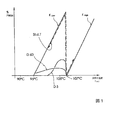
ファンモーターは、通常、冷却すべきシステムのオーバーヒーティングからの保護として使用される。冷却すべきシステムは、本明細書においては、通常、ファンの制御装置に加え、一次温度制御装置を備える。冷却システム内の温度は、この一次温度制御装置を用いて制御されることが好ましい。特に内燃機関においては、閉じた冷却回路を切り替えるサーモスタットが、一次温度制御装置として使用される。サーモスタットは、本明細書においては、ファンモーターよりもはるかにエネルギ効率良く動作し、システム内にあるエネルギがよりうまくシステム内で保持されるという利点を有する。ファンモーターは、本明細書においては、既存システムからエネルギを取り出すためだけに、多くのエネルギを使い果たしてしまうという欠点を有する。しかし、システム内にエネルギを残しておいて、それからできる限り多くの有効な出力を得ることができるようにする方が良い。したがって、冷却システム内の温度制御は、エネルギ効率の良い一次制御装置で行われ、ファンモーター及びファン制御装置は、信頼性の高い温度制御が一次制御装置を用いても維持できなくなった場合の、追加保護としてのみ使用されることが好ましい。このため、特に自動車においては、ファンは、冷却システム内の温度制御にはできる限り使用しないようにされている。しかし、先行技術による既知のファン制御装置においては、既に冒頭で述べたように、本明細書においては、冷却システム内の温度レベルが高レベルからより低い温度レベルに減少すると、問題が発生する。これらの問題を図1に例示し、同時に、本発明によるファン制御装置の好ましい運転モードを先行技術と対比させている。 Fan motors are usually used as protection from overheating of the system to be cooled. The system to be cooled typically comprises a primary temperature control device in addition to the fan control device. The temperature in the cooling system is preferably controlled using this primary temperature controller. Particularly in an internal combustion engine, a thermostat for switching a closed cooling circuit is used as a primary temperature control device. Thermostats here have the advantage that they operate much more energy efficient than fan motors and that the energy present in the system is better retained in the system. Fan motors here have the disadvantage of using up a lot of energy just to extract energy from existing systems. However, it is better to leave energy in the system so that as many effective outputs as possible can be obtained. Therefore, the temperature control in the cooling system is performed by an energy-efficient primary controller, and the fan motor and the fan controller are used when reliable temperature control cannot be maintained even by using the primary controller. It is preferably used only as additional protection. For this reason, especially in a motor vehicle, the fan is not used as much as possible for temperature control in the cooling system. However, in the known fan control devices according to the prior art, problems have arisen here as the temperature level in the cooling system is reduced from a high level to a lower temperature level, as already mentioned at the outset. These problems are illustrated in FIG. 1 and at the same time the preferred mode of operation of the fan control device according to the invention is compared with the prior art.
図1では、ファンモーターを作動するのに使用され、かつ百分率PWMで表されたパルス幅変調のパルス占有率が、冷却システム内の温度に対してプロットされている。冷却システムは、例えば2つの異なる温度レベルを設定することが可能である。1つの温度レベルは摂氏90度、第2の温度レベルは摂氏105度である。温度制御は、主に一次制御装置を用いて行われる。予め定められた温度レベルを一次制御装置で維持できない場合に、オーバーヒーティングを防止するためにファンが稼働される。このため、閾値を超えた場合に、温度が上昇するにつれて出力が増加すると、システムがより冷却されることがファンモーターによって保証される閾値が、一般に、それぞれの温度レベルに対して設けられる。図1の例示的実施形態においては、90度の温度レベルに対して摂氏95度の閾値が設けられ、摂氏105度の温度レベルに対して摂氏107度の閾値が設けられる。この閾値からの実際の温度の偏差が大きくなればなる程、設定すべき元の温度レベルに戻すために、より大きな冷却力が必要となる。ファンモーターのPWM作動については、この結果、最も簡単な場合においては、設定すべきそれぞれの温度レベルのためのファン特性曲線が、複雑な状況においては、複数のファン特性曲線からなる温度特性要因図ができ、これから、ファンモーターの出力を制御するのに必要な作動信号が、冷却システム内の冷却剤(水やクーラント液)のそれぞれの実際の温度に対して得られる。図1の例示的実施形態においては、これらの曲線は、2つの特性曲線Khigh、Klowであり、設定すべき温度レベルが摂氏105度から摂氏90度に変わる時には、基本的に、ファンを制御するために、特性曲線もKhighからKlowに変わる。しかし、冷却システムの実際の温度は、摂氏105度から摂氏90度への基準入力変数の変更に直ちに従うことができない。このため、先行技術によるファン制御装置を用いたこのシナリオでは、基準入力変数が摂氏90度に変わる時に、ファン制御装置が、冷却システムの極端なオーバーヒーティングを検出し、ファンモーターがその特性曲線の上限出力値で起動するという、以下に記載するような問題が生じる。 In FIG. 1, the pulse occupancy of the pulse width modulation used to operate the fan motor and expressed in percentage PWM is plotted against the temperature in the cooling system. The cooling system can, for example, set two different temperature levels. One temperature level is 90 degrees Celsius and the second temperature level is 105 degrees Celsius. The temperature control is mainly performed using a primary control device. When the predetermined temperature level cannot be maintained by the primary control device, the fan is operated to prevent overheating. For this reason, a threshold is generally provided for each temperature level where the fan motor ensures that the system will be more cooled as the output increases as the temperature rises when the threshold is exceeded. In the exemplary embodiment of FIG. 1, a threshold of 95 degrees Celsius is provided for a temperature level of 90 degrees, and a threshold of 107 degrees Celsius is provided for a temperature level of 105 degrees Celsius. The greater the deviation in actual temperature from this threshold, the greater the cooling power required to return to the original temperature level to be set. As a result of the PWM operation of the fan motor, in the simplest case, the fan characteristic curve for each temperature level to be set is a temperature characteristic factor diagram consisting of a plurality of fan characteristic curves in a complicated situation. From this, the actuation signals necessary to control the output of the fan motor are obtained for each actual temperature of the coolant (water or coolant fluid) in the cooling system. In the exemplary embodiment of FIG. 1, these curves are two characteristic curves K high , K low , and basically when the temperature level to be set changes from 105 degrees Celsius to 90 degrees Celsius, In order to control, the characteristic curve also changes from K high to K low . However, the actual temperature of the cooling system cannot immediately follow the change of the reference input variable from 105 degrees Celsius to 90 degrees Celsius. For this reason, in this scenario using a prior art fan controller, when the reference input variable changes to 90 degrees Celsius, the fan controller detects extreme overheating of the cooling system and the fan motor has its characteristic curve. The problem described below arises in that the system is started at the upper limit output value.
ファンモーターは、かなりのうなり音を立てる。図1は、一点鎖線を用い、かつSt−d−Tで表された、先行技術によるファンモーターのパルス幅変調に対してプロットされた作動信号のプロファイルを例示している。基準入力変数が高から低に変わる時に、作用高さが、より高い温度レベルの特性曲線Khighの低い点から、より低い温度レベルの特性曲線Klowのより高い点に飛ぶことは明らかである。本発明は、このことを防止することを目的とする。本発明によれば、このことは、基準入力変数が変わる時に、一次制御装置が冷却システム内でより低い温度レベルを設定できるようにするために、最初にファンの作動が、最小の時間、一時停止されることで達成される。最小の待ち時間が終了した後にも、一次制御装置を用いてまだより低い温度レベルに到達しない場合には、ファンモーターが最大の出力で直ちにカットインするようなことがないことを保証するための対策をとることにより、ファンモーターがうなり音を立てることを防止することが可能である。このことは、本発明に従って、ファンモーターでの突然の負荷変更を減衰するフィルタによって行われる。このことは、たとえば、ファンモーターを直接作動させるのではなく、上流フィルタを用いて、ファンの出力が漸近的にファン特性曲線の作用点に近づくことを保証する、ファンモーターの特性曲線から、ファンモーターのための作動信号を得ることによって行うことができる。この時間の間に、一次制御装置は、温度を減少させる機会を有し、このことは、静かに始動するファンによりさらにサポートされる。始動が遅延したことにより、また恐らくファンモーターのさらに減衰された始動と合わせて、本発明による方法及び本発明による制御プログラムは、曲線D5及びD60に例示されているファンモーターなどのパルス幅変調のための信号プロファイルを提供する。本明細書においては、曲線D60のプロファイルは高減衰フィルタに対応し、曲線D5のプロファイルは低減衰フィルタに対応する。 The fan motor makes a considerable roar. FIG. 1 illustrates an operating signal profile plotted against the pulse width modulation of a prior art fan motor using a dash-dot line and denoted St-d-T. It is clear that when the reference input variable changes from high to low, the working height jumps from the lower point of the higher temperature level characteristic curve K high to the higher point of the lower temperature level characteristic curve K low. . The present invention aims to prevent this. In accordance with the present invention, this means that the fan is initially turned on for a minimum amount of time to allow the primary controller to set a lower temperature level in the cooling system when the reference input variable changes. Achieved by being stopped. To ensure that the fan motor does not immediately cut in at maximum power if the primary controller is not used to reach the lower temperature level after the minimum waiting time has expired. By taking measures, it is possible to prevent the fan motor from making a roar. This is done in accordance with the present invention by a filter that attenuates sudden load changes at the fan motor. This is because, for example, the fan motor characteristic curve does not directly operate the fan motor but uses an upstream filter to ensure that the fan output asymptotically approaches the point of action of the fan characteristic curve. This can be done by obtaining an actuation signal for the motor. During this time, the primary controller has the opportunity to reduce the temperature, which is further supported by a fan that starts gently. Due to the delay in start-up, and possibly in conjunction with further damped start-up of the fan motor, the method according to the invention and the control program according to the invention can be used for pulse width modulation such as the fan motor illustrated in curves D5 and D60. Providing a signal profile for In the present specification, the profile of the curve D60 corresponds to a high attenuation filter, and the profile of the curve D5 corresponds to a low attenuation filter.
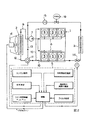
本発明によるファン制御装置は、本明細書においては、内燃機関のための冷却システムにおいて使用するのに、特に好適である。図2は、6気筒の内燃機関1のための代表的な冷却システムを示す概略図である。内燃機関に加えて、車両ラジエータ2及び加熱用熱交換器3が、冷却システム内に組み込まれる。車両ラジエータ2の冷却力は、電動ファン4の影響を受け得る。ファンの出力を調整するために、ファンの電動機は、制御装置5を用いて制御される。冷却された冷却剤が、前方フィードライン6により車両ラジエータから抽出され、燃焼気筒9のための冷却ダクト(詳細には図示せず)へと送られるために、冷却剤ポンプ7により、冷却ライン8内へと送られる。加熱された冷却剤は、戻りライン10を介して、燃焼気筒9から三方サーモスタット11に送られる。三方サーモスタット11内のバルブの位置により、冷却剤は、内燃機関からラジエータ戻り管12を介して車両ラジエータに、又はラジエータバイパス13及び冷却剤ポンプ7を介して内燃機関の冷却ライン8に戻る。
The fan control device according to the invention is particularly suitable here for use in a cooling system for an internal combustion engine. FIG. 2 is a schematic diagram showing a typical cooling system for a six-cylinder
三方サーモスタット11内のバルブの位置により、冷却システムは、本明細書においては、当技術分野で既知の方法によりバイパスモード(冷却剤をすべてラジエータバイパス13に送る)で、ハイブリッドモード(冷却剤をラジエータ戻り管12とラジエータバイパス13に所定の割合で送るモード)で、又はフル冷却回路(冷却剤をすべてラジエータ戻り管12に送る)で動作する。加熱用熱交換器3は、温度制御遮断弁14を介して、内燃機関内の冷却システムの高温分岐管に接続される。温度制御遮断弁14が開放された後に加熱用熱交換機3を通る流量は、加熱出力を調整するために、追加の電気冷却剤ポンプ15及び時間遮断弁16によって調整できる。
Depending on the position of the valve in the three-
三方サーモスタット11のバルブにある起動要素の作動は、本明細書においては、制御装置5によって設定される。この制御装置は、マイクロプロセッサの形態の論理構成要素(Logic)を含む。この制御装置は、モーター電子回路内の制御装置によって形成されるか、又はモーター電子回路の制御装置内の構成部品であることが好ましい。本明細書においては、三方サーモスタット11及びファンモーター4は、制御装置5を用いて作動される。三方サーモスタット11の加熱要素の作動は、本明細書においては、一般に知られている方法で行われる。三方サーモスタット11は、本明細書においては、冒頭で述べた一次制御装置のための作動要素であり、これは、制御装置5の三方サーモスタット11内の加熱要素を作動させるための制御プログラムとしても実施される。三方サーモスタット11を好適に作動させることにより、内燃機関のための冷却システムにおいて、特に、摂氏80度、摂氏90度、及び摂氏105度の、3つの異なる温度レベルを設定し、制御することができる。温度レベルは、本明細書においては、主に負荷制御方式で設定される。つまり、エンジンのための要件のうち、現在の要件に好適な温度が、冷却システムにおいて、ディジタル信号値の形態の、最新式の内燃機関の電子回路内で通常取ることができる内燃機関の運転モードから設定される。最も重要な影響変数とは、本明細書においては、特に、エンジン速度、空気の吸引量、又は燃焼気筒内に噴射される燃料油量から決定されるエンジン負荷である。三方サーモスタット11のみでは、もはや満足な温度制御ができなくなった場合には、追加冷却用に、ファンを使用することができる。ファンモーター4はまた、本明細書においては、制御装置5によって作動される。ファンモーターの出力は、通常、パルス幅変調で制御される。このため、必要な冷却力は、制御プログラムにより冷却システムの運転パラメーターから計算され、現在必要な冷却力が知られている場合には、それを用いて必要な冷却力を提供できるパルス幅変調の抽出率が、ファン特性曲線から決定される。好適なファンの出力を決定するための最も重要な影響変数とは、本明細書においては、現在のエンジン負荷、冷却剤設定温度、冷却剤の実際の温度、吸気温度、及びファン特性曲線である。冷却システムを用いて様々な温度レベルが設定される場合は、様々なファン特性曲線Khigh、Klowを、様々な温度レベルのために使用することができる。
The operation of the activation element in the valve of the three-
本発明によれば、次いで、制御プログラムは、冷却システム内の温度レベルが低下した場合には、少なくとも最小の待ち時間の間、ファンモーターが始動するのを防止し、最小の待ち時間の後にも、まだファンを始動することが必要な場合には、ファンの始動を減衰し、ファン特性曲線上のファン制御装置の作用点に漸近的に近づくことができるようにするように、ファンモーターを作動するために拡張される。このことは、本発明に従って、以下に図3についてより詳細に記載する制御プログラムなどを用いて可能となる。 In accordance with the present invention, the control program then prevents the fan motor from starting for at least a minimum waiting time if the temperature level in the cooling system decreases, and even after the minimum waiting time. If it is still necessary to start the fan, operate the fan motor to attenuate the fan start and asymptotically approach the point of action of the fan controller on the fan characteristic curve To be extended. This is possible according to the present invention using a control program or the like described in more detail below with respect to FIG.
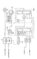
図3は、本発明による制御プログラムの、機能上の基本構成及び信号の流れを示す図である。入力端で、好ましくはエンジン制御装置から、本明細書でもエンジン制御装置から得られる信号値が、制御プログラムによって処理される。前記値とは、冷却剤設定温度、冷却剤の実際の温度、吸気温度、及び所定の時間に内燃機関が動作するエンジン負荷のための特性変数である。関連するファン特性曲線又は関連するファン特性要因図が、プログラムモジュール31を用いて、エンジン管理システムによって予め定められた冷却剤設定温度から選択され、主記憶装置内に入力される。冷却剤の実際の温度を監視することにより、プログラムモジュール31を用いて、ファンの現在の特性要因図又は現在の特性曲線において、ファンモーターが動作する作用点を見つけることができる。このような処理工程の結果、ファンモーターの出力系統への駆動信号が生じる。この駆動信号は、それによりファンモーターの制御が設定されるパルス幅変調率であることが好ましい。
FIG. 3 is a diagram showing a functional basic configuration and signal flow of the control program according to the present invention. The signal values obtained at the input, preferably from the engine control unit, also from the engine control unit in this description, are processed by the control program. The values are characteristic variables for the coolant set temperature, the actual coolant temperature, the intake air temperature, and the engine load at which the internal combustion engine operates at a predetermined time. The related fan characteristic curve or the related fan characteristic factor diagram is selected from the coolant set temperature predetermined by the engine management system using the
エンジン管理システムによって予め定められた冷却剤設定温度が変わると、プログラムモジュール31を用いて、新しい冷却剤設定温度のための、上述した工程が行われ、新しいファン特性曲線が選択される。プログラムモジュール31は、謂わば、高い冷却剤設定温度の特性曲線Khighから、より低い冷却剤設定温度の特性曲線Klowに切り替える。さらに、冷却剤の実際の温度は常に監視されており、したがって、ファンモーターの作用点も新しいファン特性曲線Klow上で見つけられ、設定することができる。冷却剤設定温度の変更及び関連する特性曲線の変更は、サブルーチン33を用いてプログラミングで評価される。冷却剤設定温度が、指定された高い温度値から指定されたより低い温度値に変わったかどうかを判断するための確認が行われる。変わった場合には、タイマ1として表された、さらなるプログラムモジュールが起動される。図3では、起動ステップは、真理変数−真という記号で例示されている。プログラムモジュールで構成されるタイマ1を用いて、ファンモーターの運転点が維持される最小の待ち時間Δt1が、冷却すべきシステムのさらなる運転パラメーターに応じて計算され、決定される。ファンモーターの出力制御装置への変更の解除については、ファンモーターの出力制御装置への変更を防止できる切り替え操作34が、タイマ1を用いて起動される形で行われることが好ましい。ファンモーターの出力制御装置の電源が切られるのに要する時間は、内燃機関の及び冷却システムの現在の運転パラメーターから決定される。5秒、30秒、及び60秒の、最小の待ち時間が設けられ、図3では、タイマ1に入力するための入力変数5、30、及び60の記号で表されている。最小の待ち時間を決定するための最も重要な影響変数とは、現在のエンジン負荷、内燃機関の現在の吸気温度、現在の冷却剤の実際の温度、及び予め定められた冷却剤設定温度での温度ジャンプの大きさである。最新式の内燃機関においては、最大3つまでの異なる冷却剤設定温度が、内燃機関の冷却システムについて予め定められ、内燃機関に必要な出力によって、エンジン管理システムによって設定される。冷却剤設定温度の代表的な温度レベルは、本明細書においては、摂氏80度、摂氏90度、及び摂氏105度である。冷却剤設定温度が摂氏105度から摂氏80度に変わる時には、60秒の最小の待ち時間が設けられ、冷却剤設定温度が摂氏105度から摂氏90度に変わる時には、30秒の最小の待ち時間が設けられる。必要な場合には、冷却システム又は内燃機関がオーバーヒーティングすることから保護するために、上述の最小の待ち時間を短縮することができる。しかし、すべての場合において、5秒の最小の待ち時間は設けられる。過負荷が生じる危険性がある場合に、最小の待ち時間をアボートできることは、内燃機関のための保護機能である。この保護機能は、冷却剤の実際の温度が、臨界値を超えた時にはいつでも起動される。たとえば、内燃機関の吸気温度が摂氏50度より上になった時、又は内燃機関の回転速度及び燃焼気筒の吸気の程度から判断された内燃機関のエンジン負荷が内燃機関の最大負荷の90パーセントより上になった時には、摂氏107度で起動される。これらの場合においては、最小の待ち時間は、タイマ1を用いて5秒に短縮されるか、又は60秒及び30秒の、2つの比較的長い待ち時間中に、内燃機関に過負荷が発生すると、その比較的長い最小の待ち時間がアボートされる。現在のエンジン負荷の計算及び現在の吸気温度の決定も、本明細書においては、エンジン管理システム又はエンジン制御装置によって行われ、本発明による制御プログラムによりさらに処理される。最も簡単な場合においては、このさらなる処理のために、タイマ1が、冷却システムの及び内燃機関の運転パラメーターが、それぞれ、許容できるものとして定められた範囲内にあるかどうかを判断するための確認を行う比較演算を含む。
When the coolant set temperature predetermined by the engine management system changes, the
タイマ1によって決定された最小の待ち時間が終了した後、低い特性曲線Klow、あるいはより正確には、低い特性曲線に基づいて計算された、ファンモーターに対する起動信号が使用可能となる。高い特性曲線Khighは切り替わらず、常にアクティブのままである。特性曲線を使用可能にすることは、図3に、切り替え操作34の記号で表され、これは、スイッチとして具現化されるか、又はプログラムによって行われる切り替え操作を用いて実施されることが好ましい。冷却剤設定温度が切り替えられた後、かつ最小の待ち時間が終了した後にも、新しい冷却剤設定温度と現在の冷却剤の実際の温度との間の温度差が大きすぎるので、ファンを再び使用すべき場合には、本発明による制御プログラムを用いて、その後可能となったファンの始動を減衰する。この結果、ファンがうなり音を立てることが防止される。プログラムモジュール31は、冷却剤の実際の温度の偏差が容認できる程度を超えているかどうかを確認することにより、ファンの始動が必要であるかどうかを、一般に知られている方法で計算する。
After minimum waiting time determined by the
ファン始動の減衰は、ファンモーターの電子システムに対する作動信号にフィルタをかける、設定可能なディジタルフィルタ32を用いて行われる。フィルタにより、フィルタの入力端にある作動信号が、漸近的に入力値に近づくフィルタ特性曲線を有するフィルタ出力部に伝達されることが保証される。このフィルタは、PT1特性と呼ばれる特性を有するフィルタであることが好ましい。これらのフィルタは、指数プロファイル、つまりどのぐらい後に出力信号が入力信号の値の66パーセントに到達したかを示す指数関数の時定数を有するフィルタ特性曲線によって定められる。指数関数の時定数を選択することにより、その効果及び設定の点で、これらのフィルタに適合させることができる。本発明はまた、サブルーチン35を用いて交換できるような、フィルタ32のフィルタ定数を具現化することによっても良い。本明細書においては、5秒の時定数及び60秒の時定数が設けられる。フィルタの時定数の切り替えは、選択操作35を起動することにより、タイマ2によって起動される。この選択工程は、図3には、切り替え工程として例示されているが、通常は、プログラムによって行われる選択ステップとして実施される。
Fan start attenuation is accomplished using a configurable
上述のフィルタ32のフィルタ設定の持続期間は、プログラムモジュールにより構成されるタイマ2を用いて設定される。タイマ2は、本明細書においては、高い時定数からより低い時定数へと、フィルタ32の時定数をリセットするのに、主に使用される。図3の例示的実施形態においては、これらは、フィルタ32のタイミング特性に影響を及ぼすための2つの時定数、5秒及び60秒である。タイマ2は、本明細書においては、プログラムモジュールにより構成されるタイマ1の出力信号のタイミングに基づく。より正確には、最小の待ち時間Δt1の終了を、タイマ2を起動するための開始時間とする。最小の待ち時間Δt1が開始したか、又は特性曲線Klowが使用可能になると、フィルタ32の時定数は、一般に、高い値、たとえば60秒に設定される。この設定は、タイマ2から切り替え信号が出た時に、フィルタ定数が、より低い値、たとえば5秒に再び設定されるまで、アクティブのままである。このリセット信号は、時間枠Δt2が終了した後に、タイマ2によって出力され、前記時間枠Δt2は、最小の待ち時間Δt1の終了の後に起こる。この追加の時間は、たとえば、一般的には60秒である。特別な状況がない場合には、フィルタ32のフィルタ設定は、時間枠Δt2の間、たとえば最小の待ち時間Δt1の終了後60秒間、アクティブのままである。
The filter setting duration of the above-described
しかし、フィルタ32の過度に高い減衰効果のためにオーバーヒーティングが生じる危険性がある場合には、所定の状況が適用される。フィルタ設定により、非常に遅いファンの始動が起こり得る場合に、このような危険性が存在する可能性がある。このため、タイマ2を用いて、保護機能が実施され、前記機能により、フィルタ設定の時間枠を短縮することができる。このため、内燃機関の吸気温度及び内燃機関の現在のエンジン負荷も、タイマ2を用いて、対応する特性変数を監視することにより、エンジン制御装置から読み取られる。吸気温度が摂氏50度の値を超えるか、又はエンジン負荷が可能な最大エンジン負荷の90パーセントの値より上になると、フィルタ32の時定数が、直ちに、5秒というより低い値にリセットされる。この結果、過負荷が生じる危険性がある場合には、ファンはより素早くその最大出力に加速することができる。ファンは、実際には、フィルタ32のより短い時定数で、より素早くアクティブとなる。
However, if there is a risk of overheating due to an excessively high attenuation effect of the
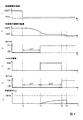
図3に表されている個々のプログラムモジュールの間の相互作用、及び本発明による制御プログラムの操作方法について、図4を参照しながら、以下に再び説明する。 The interaction between the individual program modules represented in FIG. 3 and the method of operating the control program according to the invention will be described again below with reference to FIG.
図4は、互いに関係しあう、全部で6つのタイミング図であり、この中の(1)は、冷却剤設定温度の時間プロファイルを示し、(2)は、冷却剤の実際の温度のプロファイルを示し、(3)は、タイマ1の出力部での信号レベルの時間プロファイルを示し、(4)は、フィルタ32のフィルタ定数の切り替えを示し、(5)は、タイマ2の出力部での信号レベルプロファイルを示し、最後に、(6)は、制御プログラムを用いて、ファンモーターを作動させるためのPWM比率に対して行われる設定の効果を示している。全工程の開始点は、高い値、本明細書ではたとえば摂氏105度から、より低い値、本明細書ではたとえば摂氏95度へ、冷却剤設定温度の切り替えが行われる時である。切り替えが行われると、一次制御装置が、最初に、内燃機関の冷却システム内の温度を制御するためにアクティブとなる。つまり、一次制御装置のサーモスタット11が切り替えられて、冷却剤の実際の温度が低下し始める。タイマ1によって計算され、設定された時間枠Δt1の間、ファンの出力制御装置の電源は、時間T1まで、切られたままである。最小の待ち時間Δt1が終了した後、ファンの作動が可能となる。しかし、ファンは、最初に60秒の時定数で動作するフィルタ32を用いて作動される。タイマ2は、どのぐらいの間、フィルタ設定を維持するかを決定する。フィルタ32のフィルタ定数が60秒から5秒にリセットされた後の時間枠Δt2が、タイマ2を用いて計算され、決定される。その後、つまり、時間T2から開始して、フィルタは、5秒の時定数で冷却剤設定温度の次の切り替えまで動作する。殆どの場合、フィルタの時定数をリセットしても、もはやパルス幅変調に対して何の影響も及ぼすことはない。殆どの場合、ファンモーターは、実際には、時間枠Δt2の終了後、つまり時間T2までには、新しく使用可能となった特性曲線上のその作用点まで加速されている。しかし、時定数をリセットすることは、ファン制御装置が、より短い時定数で、作用点の変更に反応することができるという利点を有する。つまり、ファンモーターは、フィルタのより短い時定数で、ファン特性曲線上の作用点の移動に、よりうまく従うことができる
FIG. 4 is a total of six timing diagrams that relate to each other, in which (1) shows the time profile of the coolant set temperature and (2) shows the profile of the actual temperature of the coolant. (3) shows the time profile of the signal level at the output section of the
一次制御装置を用いると、最小の待ち時間Δt1の終了後、冷却剤の実際の温度は、一般に、ファンモーターの起動閾値より下に低下しているはずである。この起動閾値は、本明細書で論じている例示的実施形態においては、摂氏95度である。冷却剤の温度がこの起動閾値より下に低下しない場合は、最小の待ち時間Δt1の終了後、時間T1で、ファンが減衰された始動で起動される。ファンの始動を減衰することは、ファンのPWM変調のための駆動信号が、ファン特性曲線上の作用点に漸近的に近づくという効果を有する。このプロファイルは、図4の(6)の例で示されている。冷却剤の実際の温度についての図では、ファンモーターを始動することにより、もちろん、冷却剤の実際の温度は、摂氏95度の新しい冷却剤設定温度に、より急速に低下する。冷却剤の実際の温度が時間T3で新しい設定温度に到達すると、ファンによるサポートはもはや不必要となり、ファンの電源を切ることができる。本明細書においては、PWM変調のためのパルス占有率がゼロに低下したことにより、ファンの電源が切られる。 With the primary controller, after the minimum waiting time Δt1 has expired, the actual temperature of the coolant should generally drop below the fan motor start threshold. This activation threshold is 95 degrees Celsius in the exemplary embodiment discussed herein. If the coolant temperature does not fall below this activation threshold, after the minimum waiting time Δt1, the fan is activated at time T1 with a damped start. Attenuating the start of the fan has the effect that the drive signal for PWM modulation of the fan asymptotically approaches the operating point on the fan characteristic curve. This profile is shown in the example of (6) in FIG. In the illustration of the actual temperature of the coolant, by starting the fan motor, of course, the actual temperature of the coolant will drop more rapidly to the new coolant set point of 95 degrees Celsius. When the actual temperature of the coolant reaches the new set temperature at time T3, fan support is no longer needed and the fan can be turned off. In this specification, the fan is turned off because the pulse occupancy for PWM modulation has dropped to zero.
以上のように、本発明の冷却システムによれば、自動車用のラジエータに設けられる電動ファンの制御に複数の特性曲線を用い、現在の冷却剤の温度と、その温度に対応する特性曲線上の駆動電力値(PWM値)に基づいて電動ファンを駆動する。このファンの駆動中に、設定された特性曲線が、高い側(Khigh)から低い方(Klow)に切り替わったときには、切り替え後の特性曲線値を直接供給しないで、フィルタ手段(32、33、34、35、タイマ1,2)を使って、ファンの始動を減衰させて、ファン特性曲線上のファン制御装置の作用点に漸近的に近づくことができるような形で、すなわちタイムラグを有する起動を行うように制御する。これによって、ファンが高パワーで起動することを防止でき、ファンのうなり音などの騒音の発生を防止することができる。
As described above, according to the cooling system of the present invention, a plurality of characteristic curves are used for controlling an electric fan provided in a radiator for an automobile, and the current coolant temperature and the characteristic curve corresponding to the temperature are used. The electric fan is driven based on the drive power value (PWM value). When the set characteristic curve is switched from the high side (K high ) to the low side (K low ) during driving of the fan, the characteristic value after switching is not directly supplied, and the filter means (32, 33). 34, 35,
尚、本発明は上記の実施の形態に限られることなくさまざまな応用が可能である。本形態では特性曲線は2種類であるが、複数種あってもよい。また、モータの駆動は、パルス幅変調方式だけではなく、他の公知の駆動方法であってもよい。さらに、タイマーの設定値やフィルタの時定数は、実際に適用される内燃機関や車両の特長により適宜設定すればよい。 Note that the present invention is not limited to the above-described embodiment, and various applications are possible. In this embodiment, there are two types of characteristic curves, but there may be a plurality of types. Further, the driving of the motor is not limited to the pulse width modulation method, but may be another known driving method. Furthermore, the set value of the timer and the time constant of the filter may be set as appropriate according to the features of the internal combustion engine and the vehicle that are actually applied.
1 内燃機関
2 車両ラジエータ
3 加熱用熱交換器
4 電動ファン
5 制御装置
6 フィードライン
7 冷却剤ポンプ
8 冷却ライン
9 燃焼気筒
10 戻り管
11 三方サーモスタット
12 ラジエータ戻り管
13 ラジエータバイパス
14 温度制御遮断弁
15 追加冷却剤ポンプ
16 クロック動作遮断弁
DESCRIPTION OF
Claims (19)
前記出力がファン制御装置を用いて制御され、該ファン制御装置が、前記ファンモーター(4)の前記出力と冷却システム(2、6、7、8、10、11、12)の冷却剤の実際の温度との関係を表す特性曲線(Khigh、Klow)及び冷却システムの運転パラメーターを用いて、前記ファンの前記出力を設定するものであり、前記冷却システムの前記運転パラメーターが、前記出力を制御するための基準入力変数として、複数の選択可能な冷却剤設定温度を含み、
それぞれの冷却剤設定温度に対応して、前記出力を制御するための特性曲線(Khigh、Klow)が設定されており、
前記冷却剤設定温度が高いレベルから低いレベルに変わり、これに伴い前記特性曲線(K high 、K low )が変わる時に、前記ファン制御装置が、設定可能な最小の待ち時間(Δt1)の間、前記ファンモーター(4)の運転を、前記特性曲線が前記冷却剤設定温度の変更に対応して変わることにより引き起こされる前記ファンモーター(4)の出力の急激な上昇を避けるために一定に保つことを特徴とするファン制御方法。 A method for controlling the output of a fan motor (4) used with a fan in a cooling system, comprising:
The output is controlled by means of a fan control, which controls the output of the fan motor (4) and the actual coolant in the cooling system (2, 6, 7, 8, 10, 11, 12). characteristic curve (K high, K low) representing the relationship between the temperature of using the operating parameters of and the cooling system, which sets the output of the fan, the operating parameters of the cooling system, the output Includes multiple selectable coolant setpoints as reference input variables to control,
Corresponding to each of the cooling water setpoint temperature, the characteristic curve (K high, K low) for controlling the output are set,
When the set temperature of the coolant changes from a high level to a low level , and the characteristic curves (K high , K low ) change accordingly, the fan control device performs a minimum settable waiting time (Δt1), The operation of the fan motor (4) is kept constant in order to avoid a sudden increase in the output of the fan motor (4) caused by the characteristic curve changing corresponding to the change of the coolant set temperature. A fan control method characterized by the above.
冷却剤設定温度と冷却剤の実際の温度との信号値が入力される手段と、
前記入力された冷却剤設定温度から、該冷却剤設定温度に対応する特性曲線(Khigh、Klow)を選択する手段と、
前記冷却剤設定温度が、高い温度値から低い温度値に変わったかどうかを判断するための手段と、
前記冷却剤設定温度が、高い温度値から低い温度値に変わったと判断された場合に、待ち時間(Δt1)を決定する手段と、
決定された待ち時間(Δt1)を計時する手段と、
前記待ち時間(Δt1)が経過するまで、ファンモータ(4)の運転を、前記選択された特性曲線が変化することよって引き起こされる前記ファンモーター(4)の出力の急激な上昇を避けるために一定に保つ手段と、
前記待ち時間(Δt1)が経過後に、前記選択された特性曲線に基づいてファンモーター(4)への出力信号を決定する手段と、
決定された出力信号でファンモーター(4)を運転させるために出力信号を出力する手段と、
して機能させるための制御プログラム。 Corresponding to the coolant set temperature of the cooling system, it has characteristic curves (K high , K low ) that represent the relationship between the fan motor operating signal and the actual temperature of the coolant, and is used with the fans in the cooling system A microprocessor that controls the output of the fan motor (4)
Means for inputting signal values of the coolant set temperature and the actual temperature of the coolant;
Means for selecting a characteristic curve (K high , K low ) corresponding to the coolant set temperature from the input coolant set temperature;
Means for determining whether the coolant set temperature has changed from a high temperature value to a low temperature value;
Means for determining a waiting time (Δt1) when it is determined that the coolant set temperature has changed from a high temperature value to a low temperature value;
Means for timing the determined waiting time (Δt1);
Until the waiting time (Δt1) elapses, the operation of the fan motor (4) is kept constant in order to avoid a sudden increase in the output of the fan motor (4) caused by the change of the selected characteristic curve. Means to keep
Means for determining an output signal to the fan motor (4) based on the selected characteristic curve after the waiting time (Δt1) has elapsed;
Means for outputting an output signal for operating the fan motor (4) with the determined output signal;
Control program to function.
Applications Claiming Priority (1)
| Application Number | Priority Date | Filing Date | Title |
|---|---|---|---|
| DE10348133A DE10348133A1 (en) | 2003-10-16 | 2003-10-16 | Method for driving a fan with multiple characteristics and control program for the power control of the fan |
Publications (2)
| Publication Number | Publication Date |
|---|---|
| JP2005121027A JP2005121027A (en) | 2005-05-12 |
| JP4167641B2 true JP4167641B2 (en) | 2008-10-15 |
Family
ID=34353439
Family Applications (1)
| Application Number | Title | Priority Date | Filing Date |
|---|---|---|---|
| JP2004301899A Expired - Fee Related JP4167641B2 (en) | 2003-10-16 | 2004-10-15 | Fan control for operating a fan using a plurality of characteristic curves and a control program for controlling the fan output |
Country Status (4)
| Country | Link |
|---|---|
| US (1) | US7310959B2 (en) |
| EP (1) | EP1524418A1 (en) |
| JP (1) | JP4167641B2 (en) |
| DE (1) | DE10348133A1 (en) |
Families Citing this family (24)
| Publication number | Priority date | Publication date | Assignee | Title |
|---|---|---|---|---|
| DE10336599B4 (en) * | 2003-08-08 | 2016-08-04 | Daimler Ag | Method for controlling a thermostat in a cooling circuit of an internal combustion engine |
| ATE439995T1 (en) * | 2004-04-19 | 2009-09-15 | Behr Gmbh & Co Kg | METHOD AND DEVICE FOR CONTROLLING A REFRIGERANT CIRCUIT OF AN AIR CONDITIONING SYSTEM FOR A VEHICLE |
| KR20070085335A (en) * | 2004-10-15 | 2007-08-27 | 베헤르 게엠베하 운트 콤파니 카게 | Ventilator system for a motor vehicle |
| US7484925B2 (en) * | 2005-05-10 | 2009-02-03 | Emp Advanced Development, Llc | Rotary axial fan assembly |
| US20070237656A1 (en) * | 2006-04-11 | 2007-10-11 | Pipkorn Nicholas T | Rotary fan with encapsulated motor assembly |
| FR2901311A1 (en) * | 2006-05-16 | 2007-11-23 | Renault Sas | Internal combustion engine temperature regulating method for vehicle, involves launching blocking time out so that threshold value of temperature transmitted to regulation unit, remains constant irrespective of variations of amplitude |
| KR20080042397A (en) * | 2006-11-09 | 2008-05-15 | 삼성전자주식회사 | Apparatus for operating of air conditioner system and control method thereof |
| US8833098B2 (en) * | 2007-07-16 | 2014-09-16 | Earth To Air Systems, Llc | Direct exchange heating/cooling system |
| US8825284B2 (en) * | 2007-08-01 | 2014-09-02 | Cummins Inc. | Automatic fan curve selection |
| US20110239666A1 (en) * | 2010-03-12 | 2011-10-06 | Allen Jack W | Heat transfer processes and equipment for industrial applications |
| US8714116B2 (en) * | 2011-05-12 | 2014-05-06 | Cnh Industrial America Llc | Engine cooling fan speed control system |
| JP5853690B2 (en) * | 2011-12-28 | 2016-02-09 | 日産自動車株式会社 | Automatic engine stop control device for vehicle |
| CN103115016A (en) * | 2013-03-18 | 2013-05-22 | 江苏苏南药业实业有限公司 | Double-effect extraction pot cooling fan energy-saving device and temperature control method |
| DE102014006275A1 (en) * | 2014-05-02 | 2015-11-19 | Khs Corpoplast Gmbh | Method and device for tempering preforms |
| US9551275B2 (en) * | 2014-08-07 | 2017-01-24 | Caterpillar Inc. | Cooling system having pulsed fan control |
| CN105402148B (en) * | 2014-08-21 | 2019-01-04 | 中兴通讯股份有限公司 | A kind of method and device of PTN device fan speed-regulating |
| US9353673B2 (en) * | 2014-10-23 | 2016-05-31 | Caterpillar Inc. | Engine fan control system and method |
| WO2016105315A1 (en) * | 2014-12-24 | 2016-06-30 | Otokar Otomotiv Ve Savunma Sanayi Anonim Sirketi | A multiplex hydrofan system |
| US9752492B2 (en) | 2015-03-06 | 2017-09-05 | Deere & Company | Fan control system and method |
| US9605583B2 (en) * | 2015-03-06 | 2017-03-28 | Deere & Company | Fan control system and method |
| US10648713B2 (en) | 2017-02-08 | 2020-05-12 | Titan, Llc | Industrial heat transfer unit |
| EP3621844A1 (en) | 2017-05-11 | 2020-03-18 | Sew-Eurodrive GmbH & Co. KG | Method for controlling a fan of a mobile part, and device for carrying out such a method |
| US11058027B2 (en) * | 2019-04-03 | 2021-07-06 | Lenovo Enterprises Solutions (Singapore) Pte. Ltd. | Systems and methods for controlling air distribution to electronic components |
| CN116241495B (en) * | 2023-03-10 | 2024-08-27 | 中国航发沈阳发动机研究所 | Fan characteristic recording method based on complete machine test run condition |
Family Cites Families (5)
| Publication number | Priority date | Publication date | Assignee | Title |
|---|---|---|---|---|
| DE3342031B4 (en) * | 1982-11-23 | 2005-01-13 | Papst Licensing Gmbh & Co. Kg | Circuit arrangement for speed control of an electric motor |
| DE19728814A1 (en) * | 1997-07-05 | 1999-01-07 | Behr Thermot Tronik Gmbh & Co | Cooling system for an internal combustion engine of a motor vehicle |
| JPH11229876A (en) * | 1997-12-10 | 1999-08-24 | Denso Corp | Cooling system for vehicle |
| US6045482A (en) * | 1998-03-02 | 2000-04-04 | Cummins Engine Company, Inc. | System for controlling air flow to a cooling system of an internal combustion engine |
| US6291956B1 (en) * | 2000-05-02 | 2001-09-18 | Taiwan Da-Long Industrial Co., Ltd. | Temperature controlled radiating fan |
-
2003
- 2003-10-16 DE DE10348133A patent/DE10348133A1/en not_active Withdrawn
-
2004
- 2004-10-06 EP EP04023782A patent/EP1524418A1/en not_active Withdrawn
- 2004-10-15 JP JP2004301899A patent/JP4167641B2/en not_active Expired - Fee Related
- 2004-10-18 US US10/966,103 patent/US7310959B2/en active Active
Also Published As
| Publication number | Publication date |
|---|---|
| JP2005121027A (en) | 2005-05-12 |
| DE10348133A1 (en) | 2005-05-12 |
| US7310959B2 (en) | 2007-12-25 |
| EP1524418A1 (en) | 2005-04-20 |
| US20050081542A1 (en) | 2005-04-21 |
Similar Documents
| Publication | Publication Date | Title |
|---|---|---|
| JP4167641B2 (en) | Fan control for operating a fan using a plurality of characteristic curves and a control program for controlling the fan output | |
| EP0965737B1 (en) | Internal combustion engine total cooling control system | |
| JP4164690B2 (en) | Method for controlling the heat of an internal combustion engine for automobiles | |
| US6101987A (en) | Method and apparatus for combined operation of a thermostatic valve and a radiator fan | |
| JP5330945B2 (en) | Hydraulic system and wind power generator equipped with the same | |
| JP4091937B2 (en) | Cooling system for automotive internal combustion engine | |
| US20030089319A1 (en) | Method for operating an internal combustion engine, and motor vehicle | |
| CN102384618A (en) | Method for controlling opening of electronic expansion valve in heat pump water heater system | |
| CN113818981B (en) | Warming method based on temperature control module, vehicle and storage medium | |
| EP3211194B1 (en) | Vehicle and method for controlling a variable speed water pump | |
| JP2006214281A (en) | Cooling device of engine | |
| JP2004360509A (en) | Cooling system for internal combustion engine | |
| US6571752B1 (en) | Cooling system and method for an internal combustion engine | |
| US8978599B2 (en) | Cooling apparatus of internal combustion engine for vehicle | |
| JP2012102639A (en) | Engine cooling system | |
| JP2007502381A (en) | Method for adjusting refrigerant flow with heating shut-off valve | |
| JP2010065608A (en) | Cooling system of internal combustion engine | |
| JP7206757B2 (en) | Cooling system for vehicle and control method thereof | |
| WO2013027495A1 (en) | Cooling control device for engine | |
| JP4337212B2 (en) | Cooling device for liquid-cooled internal combustion engine | |
| JP2008121434A (en) | Vehicle cooling system | |
| JPH074285A (en) | Automatic warming-up system | |
| KR102186161B1 (en) | Controller for automotive vehicles | |
| JP2901691B2 (en) | Compressor control device for vehicle air conditioner | |
| KR20100041254A (en) | Method for controlling car air-conditioner |
Legal Events
| Date | Code | Title | Description |
|---|---|---|---|
| A621 | Written request for application examination |
Free format text: JAPANESE INTERMEDIATE CODE: A621 Effective date: 20050627 |
|
| RD02 | Notification of acceptance of power of attorney |
Free format text: JAPANESE INTERMEDIATE CODE: A7422 Effective date: 20070710 |
|
| RD04 | Notification of resignation of power of attorney |
Free format text: JAPANESE INTERMEDIATE CODE: A7424 Effective date: 20070720 |
|
| RD04 | Notification of resignation of power of attorney |
Free format text: JAPANESE INTERMEDIATE CODE: A7424 Effective date: 20070710 |
|
| A131 | Notification of reasons for refusal |
Free format text: JAPANESE INTERMEDIATE CODE: A131 Effective date: 20071114 |
|
| RD03 | Notification of appointment of power of attorney |
Free format text: JAPANESE INTERMEDIATE CODE: A7423 Effective date: 20071122 |
|
| A521 | Request for written amendment filed |
Free format text: JAPANESE INTERMEDIATE CODE: A523 Effective date: 20080214 |
|
| A131 | Notification of reasons for refusal |
Free format text: JAPANESE INTERMEDIATE CODE: A131 Effective date: 20080311 |
|
| A521 | Request for written amendment filed |
Free format text: JAPANESE INTERMEDIATE CODE: A523 Effective date: 20080611 |
|
| TRDD | Decision of grant or rejection written | ||
| A01 | Written decision to grant a patent or to grant a registration (utility model) |
Free format text: JAPANESE INTERMEDIATE CODE: A01 Effective date: 20080729 |
|
| A01 | Written decision to grant a patent or to grant a registration (utility model) |
Free format text: JAPANESE INTERMEDIATE CODE: A01 |
|
| A61 | First payment of annual fees (during grant procedure) |
Free format text: JAPANESE INTERMEDIATE CODE: A61 Effective date: 20080801 |
|
| R150 | Certificate of patent or registration of utility model |
Free format text: JAPANESE INTERMEDIATE CODE: R150 |
|
| FPAY | Renewal fee payment (event date is renewal date of database) |
Free format text: PAYMENT UNTIL: 20110808 Year of fee payment: 3 |
|
| LAPS | Cancellation because of no payment of annual fees |