EP1509687B1 - Method for regulating the heat of an internal combustion engine for vehicles - Google Patents
Method for regulating the heat of an internal combustion engine for vehicles Download PDFInfo
- Publication number
- EP1509687B1 EP1509687B1 EP03714903A EP03714903A EP1509687B1 EP 1509687 B1 EP1509687 B1 EP 1509687B1 EP 03714903 A EP03714903 A EP 03714903A EP 03714903 A EP03714903 A EP 03714903A EP 1509687 B1 EP1509687 B1 EP 1509687B1
- Authority
- EP
- European Patent Office
- Prior art keywords
- internal combustion
- combustion engine
- coolant
- temperature
- coolant temperature
- Prior art date
- Legal status (The legal status is an assumption and is not a legal conclusion. Google has not performed a legal analysis and makes no representation as to the accuracy of the status listed.)
- Expired - Fee Related
Links
Images
Classifications
-
- F—MECHANICAL ENGINEERING; LIGHTING; HEATING; WEAPONS; BLASTING
- F01—MACHINES OR ENGINES IN GENERAL; ENGINE PLANTS IN GENERAL; STEAM ENGINES
- F01P—COOLING OF MACHINES OR ENGINES IN GENERAL; COOLING OF INTERNAL-COMBUSTION ENGINES
- F01P7/00—Controlling of coolant flow
- F01P7/14—Controlling of coolant flow the coolant being liquid
- F01P7/16—Controlling of coolant flow the coolant being liquid by thermostatic control
- F01P7/167—Controlling of coolant flow the coolant being liquid by thermostatic control by adjusting the pre-set temperature according to engine parameters, e.g. engine load, engine speed
-
- F—MECHANICAL ENGINEERING; LIGHTING; HEATING; WEAPONS; BLASTING
- F02—COMBUSTION ENGINES; HOT-GAS OR COMBUSTION-PRODUCT ENGINE PLANTS
- F02M—SUPPLYING COMBUSTION ENGINES IN GENERAL WITH COMBUSTIBLE MIXTURES OR CONSTITUENTS THEREOF
- F02M26/00—Engine-pertinent apparatus for adding exhaust gases to combustion-air, main fuel or fuel-air mixture, e.g. by exhaust gas recirculation [EGR] systems
- F02M26/13—Arrangement or layout of EGR passages, e.g. in relation to specific engine parts or for incorporation of accessories
- F02M26/22—Arrangement or layout of EGR passages, e.g. in relation to specific engine parts or for incorporation of accessories with coolers in the recirculation passage
- F02M26/23—Layout, e.g. schematics
- F02M26/28—Layout, e.g. schematics with liquid-cooled heat exchangers
-
- F—MECHANICAL ENGINEERING; LIGHTING; HEATING; WEAPONS; BLASTING
- F01—MACHINES OR ENGINES IN GENERAL; ENGINE PLANTS IN GENERAL; STEAM ENGINES
- F01P—COOLING OF MACHINES OR ENGINES IN GENERAL; COOLING OF INTERNAL-COMBUSTION ENGINES
- F01P5/00—Pumping cooling-air or liquid coolants
- F01P5/10—Pumping liquid coolant; Arrangements of coolant pumps
- F01P2005/105—Using two or more pumps
-
- F—MECHANICAL ENGINEERING; LIGHTING; HEATING; WEAPONS; BLASTING
- F01—MACHINES OR ENGINES IN GENERAL; ENGINE PLANTS IN GENERAL; STEAM ENGINES
- F01P—COOLING OF MACHINES OR ENGINES IN GENERAL; COOLING OF INTERNAL-COMBUSTION ENGINES
- F01P7/00—Controlling of coolant flow
- F01P7/14—Controlling of coolant flow the coolant being liquid
- F01P2007/146—Controlling of coolant flow the coolant being liquid using valves
-
- F—MECHANICAL ENGINEERING; LIGHTING; HEATING; WEAPONS; BLASTING
- F01—MACHINES OR ENGINES IN GENERAL; ENGINE PLANTS IN GENERAL; STEAM ENGINES
- F01P—COOLING OF MACHINES OR ENGINES IN GENERAL; COOLING OF INTERNAL-COMBUSTION ENGINES
- F01P2023/00—Signal processing; Details thereof
-
- F—MECHANICAL ENGINEERING; LIGHTING; HEATING; WEAPONS; BLASTING
- F01—MACHINES OR ENGINES IN GENERAL; ENGINE PLANTS IN GENERAL; STEAM ENGINES
- F01P—COOLING OF MACHINES OR ENGINES IN GENERAL; COOLING OF INTERNAL-COMBUSTION ENGINES
- F01P2023/00—Signal processing; Details thereof
- F01P2023/08—Microprocessor; Microcomputer
-
- F—MECHANICAL ENGINEERING; LIGHTING; HEATING; WEAPONS; BLASTING
- F01—MACHINES OR ENGINES IN GENERAL; ENGINE PLANTS IN GENERAL; STEAM ENGINES
- F01P—COOLING OF MACHINES OR ENGINES IN GENERAL; COOLING OF INTERNAL-COMBUSTION ENGINES
- F01P2025/00—Measuring
- F01P2025/04—Pressure
-
- F—MECHANICAL ENGINEERING; LIGHTING; HEATING; WEAPONS; BLASTING
- F01—MACHINES OR ENGINES IN GENERAL; ENGINE PLANTS IN GENERAL; STEAM ENGINES
- F01P—COOLING OF MACHINES OR ENGINES IN GENERAL; COOLING OF INTERNAL-COMBUSTION ENGINES
- F01P2025/00—Measuring
- F01P2025/08—Temperature
- F01P2025/13—Ambient temperature
-
- F—MECHANICAL ENGINEERING; LIGHTING; HEATING; WEAPONS; BLASTING
- F01—MACHINES OR ENGINES IN GENERAL; ENGINE PLANTS IN GENERAL; STEAM ENGINES
- F01P—COOLING OF MACHINES OR ENGINES IN GENERAL; COOLING OF INTERNAL-COMBUSTION ENGINES
- F01P2025/00—Measuring
- F01P2025/08—Temperature
- F01P2025/32—Engine outcoming fluid temperature
-
- F—MECHANICAL ENGINEERING; LIGHTING; HEATING; WEAPONS; BLASTING
- F01—MACHINES OR ENGINES IN GENERAL; ENGINE PLANTS IN GENERAL; STEAM ENGINES
- F01P—COOLING OF MACHINES OR ENGINES IN GENERAL; COOLING OF INTERNAL-COMBUSTION ENGINES
- F01P2025/00—Measuring
- F01P2025/08—Temperature
- F01P2025/33—Cylinder head temperature
-
- F—MECHANICAL ENGINEERING; LIGHTING; HEATING; WEAPONS; BLASTING
- F01—MACHINES OR ENGINES IN GENERAL; ENGINE PLANTS IN GENERAL; STEAM ENGINES
- F01P—COOLING OF MACHINES OR ENGINES IN GENERAL; COOLING OF INTERNAL-COMBUSTION ENGINES
- F01P2025/00—Measuring
- F01P2025/08—Temperature
- F01P2025/42—Intake manifold temperature
-
- F—MECHANICAL ENGINEERING; LIGHTING; HEATING; WEAPONS; BLASTING
- F01—MACHINES OR ENGINES IN GENERAL; ENGINE PLANTS IN GENERAL; STEAM ENGINES
- F01P—COOLING OF MACHINES OR ENGINES IN GENERAL; COOLING OF INTERNAL-COMBUSTION ENGINES
- F01P2025/00—Measuring
- F01P2025/08—Temperature
- F01P2025/46—Engine parts temperature
-
- F—MECHANICAL ENGINEERING; LIGHTING; HEATING; WEAPONS; BLASTING
- F01—MACHINES OR ENGINES IN GENERAL; ENGINE PLANTS IN GENERAL; STEAM ENGINES
- F01P—COOLING OF MACHINES OR ENGINES IN GENERAL; COOLING OF INTERNAL-COMBUSTION ENGINES
- F01P2025/00—Measuring
- F01P2025/08—Temperature
- F01P2025/50—Temperature using two or more temperature sensors
-
- F—MECHANICAL ENGINEERING; LIGHTING; HEATING; WEAPONS; BLASTING
- F01—MACHINES OR ENGINES IN GENERAL; ENGINE PLANTS IN GENERAL; STEAM ENGINES
- F01P—COOLING OF MACHINES OR ENGINES IN GENERAL; COOLING OF INTERNAL-COMBUSTION ENGINES
- F01P2060/00—Cooling circuits using auxiliaries
- F01P2060/02—Intercooler
-
- F—MECHANICAL ENGINEERING; LIGHTING; HEATING; WEAPONS; BLASTING
- F01—MACHINES OR ENGINES IN GENERAL; ENGINE PLANTS IN GENERAL; STEAM ENGINES
- F01P—COOLING OF MACHINES OR ENGINES IN GENERAL; COOLING OF INTERNAL-COMBUSTION ENGINES
- F01P2060/00—Cooling circuits using auxiliaries
- F01P2060/08—Cabin heater
-
- F—MECHANICAL ENGINEERING; LIGHTING; HEATING; WEAPONS; BLASTING
- F01—MACHINES OR ENGINES IN GENERAL; ENGINE PLANTS IN GENERAL; STEAM ENGINES
- F01P—COOLING OF MACHINES OR ENGINES IN GENERAL; COOLING OF INTERNAL-COMBUSTION ENGINES
- F01P7/00—Controlling of coolant flow
- F01P7/02—Controlling of coolant flow the coolant being cooling-air
- F01P7/04—Controlling of coolant flow the coolant being cooling-air by varying pump speed, e.g. by changing pump-drive gear ratio
-
- F—MECHANICAL ENGINEERING; LIGHTING; HEATING; WEAPONS; BLASTING
- F01—MACHINES OR ENGINES IN GENERAL; ENGINE PLANTS IN GENERAL; STEAM ENGINES
- F01P—COOLING OF MACHINES OR ENGINES IN GENERAL; COOLING OF INTERNAL-COMBUSTION ENGINES
- F01P7/00—Controlling of coolant flow
- F01P7/02—Controlling of coolant flow the coolant being cooling-air
- F01P7/10—Controlling of coolant flow the coolant being cooling-air by throttling amount of air flowing through liquid-to-air heat exchangers
- F01P7/12—Controlling of coolant flow the coolant being cooling-air by throttling amount of air flowing through liquid-to-air heat exchangers by thermostatic control
-
- F—MECHANICAL ENGINEERING; LIGHTING; HEATING; WEAPONS; BLASTING
- F01—MACHINES OR ENGINES IN GENERAL; ENGINE PLANTS IN GENERAL; STEAM ENGINES
- F01P—COOLING OF MACHINES OR ENGINES IN GENERAL; COOLING OF INTERNAL-COMBUSTION ENGINES
- F01P7/00—Controlling of coolant flow
- F01P7/14—Controlling of coolant flow the coolant being liquid
- F01P7/16—Controlling of coolant flow the coolant being liquid by thermostatic control
- F01P7/164—Controlling of coolant flow the coolant being liquid by thermostatic control by varying pump speed
-
- F—MECHANICAL ENGINEERING; LIGHTING; HEATING; WEAPONS; BLASTING
- F02—COMBUSTION ENGINES; HOT-GAS OR COMBUSTION-PRODUCT ENGINE PLANTS
- F02D—CONTROLLING COMBUSTION ENGINES
- F02D41/00—Electrical control of supply of combustible mixture or its constituents
- F02D41/02—Circuit arrangements for generating control signals
- F02D41/14—Introducing closed-loop corrections
- F02D41/1438—Introducing closed-loop corrections using means for determining characteristics of the combustion gases; Sensors therefor
- F02D41/1444—Introducing closed-loop corrections using means for determining characteristics of the combustion gases; Sensors therefor characterised by the characteristics of the combustion gases
- F02D41/1446—Introducing closed-loop corrections using means for determining characteristics of the combustion gases; Sensors therefor characterised by the characteristics of the combustion gases the characteristics being exhaust temperatures
Abstract
Description
Die Erfindung betrifft ein Verfahren zur Wärmeregulierung einer Brennkraftmaschine für Fahrzeuge mit einem Kühlmittelkreislauf und ansteuerbaren Einrichtungen zur Beeinflussung des Wärmehaushalts der Brennkraftmaschine, wobei eine Kühlmitteltemperatur und weitere Betriebsparameter der Brennkraftmaschine erfasst werden und die ansteuerbaren Einrichtungen in Abhängigkeit der Kühlmitteltemperatur und der weiteren Betriebsparameter der Brennkraftmaschine angesteuert werden.The invention relates to a method for regulating the heat of an internal combustion engine for vehicles with a coolant circuit and controllable means for influencing the heat balance of the internal combustion engine, wherein a coolant temperature and other operating parameters of the internal combustion engine are detected and the controllable devices are controlled in dependence on the coolant temperature and the further operating parameters of the internal combustion engine ,
Aus der
Aus der
Aus der
Aus der deutschen Offenlegungsschrift
Betrieb genommen und geregelt werden. Können mittels des Kühlmittelkreislaufs die Temperaturen der Brennkraftmaschine nicht beherrscht werden, ist vorgesehen, zur Sicherheit die Leistung der Brennkraftmaschine zu reduzieren.Be taken and regulated. Can by means of the coolant circuit, the temperatures of the internal combustion engine can not be controlled, it is provided to reduce the performance of the internal combustion engine for safety.
Mit der Erfindung soll ein Verfahren zur Wärmeregulierung einer Brennkraftmaschine für Fahrzeuge angegeben werden, das mit geringen Änderungen für verschiedene Verbrennungsmotoren mit abweichenden Komponenten einsetzbar ist.With the invention, a method for heat regulation of an internal combustion engine for vehicles is to be specified, which can be used with minor changes for different internal combustion engines with different components.
Erfindungsgemäß ist hierzu ein Verfahren zur Wärmeregulierung einer Brennkraftmaschine für Fahrzeuge mit einem Kühlmittelkreislauf gemäss Anspruch 1 vorgesehenAccording to the invention, a method for heat regulation of an internal combustion engine for vehicles with a coolant circuit according to
Auf diese Weise ist eine Max-Verknüpfung der ermittelten Ausgangswerte bereitgestellt, indem lediglich der größere Ausgangswert in die Stellgröße umgesetzt wird. Durch eine solche Max-Verknüpfung wird eine Schnittstelle für eine Erweiterung der Regelungsstruktur geschaffen. Zusätzliche Funktionalitäten oder Anforderungen können an der Max-Verknüpfung eingespeist werden, ohne weitere Änderungen an der übrigen Regelungsstruktur zu erfordern. Beispielsweise können Anforderungen aus einer Klimasteuerung oder aus motorischen Belangen wegen einer Kühlung der Abgasrückführung oder einer Ladeluftkühlung dadurch berücksichtigt werden, dass anhand dieser Anforderungen ein Ausgangswert ermittelt, mit den übrigen Ausgangswerten verglichen und dann berücksichtigt wird, wenn er größer als die übrigen ermittelten Ausgangswerte ist.In this way, a max combination of the determined output values is provided by only converting the larger output value into the manipulated variable. Such a Max link creates an interface for an extension of the control structure. Additional functionalities or requirements can be fed to the Max link without requiring further changes to the rest of the control structure. For example, requirements from a climate control or engine concerns due to cooling of the exhaust gas recirculation or intercooling be taken into account by using these requirements, an output value is determined, compared with the other output values and then taken into account when it is greater than the other determined output values.
Indem die Regelung über die Korrektur eines Grundkennfelds erfolgt, ist die Regelungsstruktur für unterschiedliche Anwendungen geeignet, da zur Anpassung an verschiedene Verbrennungsmotoren lediglich das Grundkennfeld oder der Korrekturregler verändert werden müssen. Dadurch können verschiedene Motoren unterschiedlichen Komponenten mit der gleichen Regelungsstruktur betrieben werden.By controlling the correction of a basic map, the control structure is suitable for different applications, since only the basic map or the correction controller must be changed to adapt to different internal combustion engines. As a result, different engines different components can be operated with the same control structure.
In Weiterbildung der Erfindung wird bei der Bestimmung einer Stellgröße eine Hystereskennlinie angewendet.In a further development of the invention, a hysteresis curve is used in the determination of a manipulated variable.
Eine solche Hysteresekennlinie kann sowohl bei den Reglern als auch auf das Grundkennfeld angewendet werden, um vor allem in Übergangsbereichen, beispielsweise beim Einschalten der Kühlmittelpumpe, ein unkontrolliertes Schalten zu verhindern.Such a hysteresis characteristic can be applied to both the controllers and the basic map, especially in transition areas, for example when switching on the coolant pump to prevent uncontrolled switching.
In Weiterbildung der Erfindung erfolgt eine Bestimmung von Sollwerten einer Kühlmitteltemperatur und einer Bauteiltemperatur der Brennkraftmaschine mittels Kennfeldern in Abhängigkeit einer Drehzahl und einer Einspritzmenge der Brennkraftmaschine.In a development of the invention, a determination of desired values of a coolant temperature and of a component temperature of the internal combustion engine takes place by means of characteristic diagrams as a function of a rotational speed and an injection quantity of the internal combustion engine.
Auf diese Weise können die Sollwerte für Kühlmittel- und Bauteiltemperatur betriebspunktabhängig vorgegeben werden.In this way, the setpoints for coolant and component temperature can be specified depending on the operating point.
In Weiterbildung der Erfindung sind mehrere Zustände des Systems aus Brennkraftmaschine und Kühlmittelkreislauf definiert, die jeweils unterschiedlichen Werten der Kühlmitteltemperatur und/oder der weiteren Betriebsparameter zugeordnet sind und in denen die ansteuerbaren Einrichtungen zur Regelung wenigstens der Kühlmitteltemperatur wenigstens teilweise unterschiedlich angesteuert werden.In a development of the invention, a plurality of states of the system of internal combustion engine and coolant circuit are defined, which are respectively assigned to different values of the coolant temperature and / or the further operating parameters and in which the controllable devices for controlling at least the coolant temperature are at least partially controlled differently.
Durch diese Maßnahmen kann eine übersichtliche Regelungsstruktur erreicht werden. Darüber hinaus können in den verschiedenen Zuständen unterschiedliche Regelcharakteristiken vorgesehen werden oder ansteuerbare Einrichtungen ohne jede Regelung auf Maximal- oder Nulldurchsatz gestellt werden.Through these measures, a clear regulatory structure can be achieved. In addition, different control characteristics can be provided in the different states or controllable devices can be set to maximum or zero flow rates without any regulation.
In Weiterbildung der Erfindung wird ein Wechsel in die verschiedenen Zustände durch Über- oder Unterschreiten vorgegebener Grenzwerte eine Umgebungstemperatur, einer Bauteiltemperatur der Brennkraftmaschine, einer Kühlmitteltemperatur, einer Ladelufttemperatur und/oder eines Drucks eines Klimakompressors ausgelöst und in den einzelnen Zuständen werden zur Regelung einer Kühlmitteltemperatur und einer Bauteiltemperatur der Brennkraftmaschine Einstellungen einer Kühlmittelpumpe, einer Heizungspumpe, eines Mischventils zwischen einem Kühler- und einem Bypasskreis, einer Kühlerjalousie, eines Kühlerlüfters, eines Klimakompressors und/oder einer Einspritzanlage der Brennkraftmaschine verändert.In a further development of the invention, a change in the various states by exceeding or falling below predetermined limits an ambient temperature, a component temperature of the internal combustion engine, a coolant temperature, a charge air temperature and / or pressure of an air conditioning compressor is triggered and in the individual states are to control a coolant temperature and a component temperature of the internal combustion engine settings of a coolant pump, a heating pump, a mixing valve between a radiator and a bypass circuit, a radiator shutter, a radiator fan, an air compressor and / or an injection system of the internal combustion engine changed.
Durch diese Maßnahmen ist der jeweils aktuelle Zustand des Wärmehaushalts einer Brennkraftmaschine genau bekannt, und es kann schnell auf Veränderungen des Wärmehaushalts reagiert werden. Dadurch muss lediglich ein geringer Sicherheitsabstand von kritischen Bereichen der Brennkraftmaschine eingehalten werden, wodurch ein optimales Wärmemanagement erreicht werden kann. Auf diese Weise kann bei geringem Verbrauch, Verschleiß sowie geringer Emission ein guter Heiz- bzw. Klimakomfort erreicht werden.By these measures, the current state of the heat balance of an internal combustion engine is precisely known, and it can be quickly responded to changes in heat balance. As a result, only a small safety distance from critical areas of the internal combustion engine must be maintained, whereby an optimal thermal management can be achieved. In this way, a good heating or climate comfort can be achieved with low consumption, wear and low emission.
Weitere Vorteile der Erfindung ergeben sich aus den Ansprüchen und der folgenden Beschreibung einer bevorzugten Ausführungsform der Erfindung im Zusammenhang mit den Zeichnungen. In den Zeichnungen zeigen:
- Fig. 1
- eine schematische Darstellung einer Brennkraftma- schine für ein Fahrzeug zur Durchführung des erfin- dungsgemäßen Verfahrens,
- Fig. 2
- eine Darstellung der Eingangs- und Ausgangsgrößen des erfindungsgemäßen Verfahrens,
- Fig. 3
- eine detailliertere Darstellung der Bildung von Stellgrößen bei dem erfindungsgemäßen Verfahren und
- Fig. 4
- eine Darstellung der verschiedenen möglichen Zu- stände, die das System aus Brennkraftmaschine und Kühlmittelkreislauf einnehmen kann.
- Fig. 1
- 2 a schematic representation of an internal combustion engine for a vehicle for carrying out the method according to the invention;
- Fig. 2
- a representation of the input and output variables of the method according to the invention,
- Fig. 3
- a more detailed representation of the formation of variables in the inventive method and
- Fig. 4
- a representation of the various possible states that can take the system of internal combustion engine and coolant circuit.
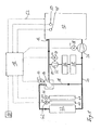
In der schematischen Darstellung der
Stromabwärts des Fahrzeugkühlers 22 mündet die Bypassleitung 18 wieder in eine Hauptleitung 24, die zu einer Kühlmittelpumpe 26 führt. Die Kühlmittelpumpe 26 wird mechanisch vom Verbrennungsmotor 10 angetrieben und ist mit einer vom Steuergerät 18 ansteuerbaren Magnetkupplung 28 versehen. Mittels der Magnetkupplung 28 kann die Kühlmittelpumpe 26 auch bei laufendem Verbrennungsmotor 10 an- bzw. ausgeschaltet werden. Anstelle einer mechanisch angetriebenen Kühlmittelpumpe könnte auch eine elektrisch angetriebene Kühlmittelpumpe zum Einsatz kommen. Ausgehend von der Kühlmittelpumpe 26 gelangt das Kühlmittel wieder in den Verbrennungsmotor 10.Downstream of the vehicle radiator 22, the
Stromaufwärts des Mischventils 14 zweigt eine Heizungskreisleitung 30 von der, den Kühlmittelauslass 12 und das Mischventil 14 verbindenden Leitung ab. Die Heizungskreisleitung 30 führt zunächst zu einer Heizungspumpe 32, die mittels eines Elektromotors 34 angetrieben wird. Der Elektromotor 34 wird vom Steuergerät 18 mittels pulsweitenmodulierter Signale angesteuert. Stromabwärts der Heizungspumpe 32 führt die Heizungskreisleitung 30 zu einem Abgasrückführ-Wärmetauscher 36. Dem Abgasrückführ-Wärmetauscher 36 in Reihe nachgeschaltet ist ein Heizungs-Wärmetauscher 38. Ausgehend von dem Heizungs-Wärmetauscher 38 führt die Heizungskreisleitung 30 dann zu der Hauptleitung 24, die zur Kühlmittelpumpe 26 führt.Upstream of the mixing
Der Fahrzeugkühler 22 ist mit einer Kühlerjalousie 40, die mittels eines Elektromotors 42 verstellt werden kann, sowie einem Lüfter 44 versehen, der mittels eines Elektromotors 46 angetrieben wird. Durch Ansteuerung der Elektromotoren 42 bzw. 46 kann mittels des Steuergeräts 18 eine Einstellung der Kühlerjalousie 40 bzw. eine Drehzahl des Lüfters 44 verändert werden.The vehicle radiator 22 is provided with a
Das zentrale Steuergerät 18 erhält Eingangssignale von einem Kühlmitteltemperatursensor 48 sowie einem Stegtemperatursensor 50 in dem Verbrennungsmotor 10. Der Kühlmitteltemperatursensor 48 misst eine Temperatur des Kühlmittels am Austritt 12 des Verbrennungsmotors 10 und der Stegtemperatursensor 50 misst eine Temperatur eines Materialbereichs zwischen den Auslassventilen des Verbrennungsmotors 10. Durch eine strichliert dargestellte Verbindung 52 ist ein Datenaustausch zwischen dem Verbrennungsmotor 10 und dem zentralen Steuergerät 18 verdeutlicht. Mittels eines Datenaustauschs über die Verbindung 52 erhält das zentrale Steuergerät 18 Istwerte von Betriebsparametern des Verbrennungsmotors 10 gibt Stellgrößen für den Betrieb des Verbrennungsmotors 10 vor, beispielsweise Einspritzmenge, Drosselklappenstellung, Zündzeitpunkt und dergleichen. Darüber hinaus erhält das zentrale Steuergerät 18 von einem Block 54 Eingangssignale, die Heizungs- und Klimaanforderungen betreffen. Wird beispielsweise vom Block 54 eine erhöhte Klimatisierungsleistung angefordert, kann das Steuergerät 18 einerseits eine Motorlast erhöhen und andererseits Maßnahmen treffen, um die dann erhöhte Wärmemenge über den Kühlmittelkreislauf abführen zu können.The
Um eine bedarfsgerechte Motorkühlung zu ermöglichen, ist in das Steuergerät 18 eine Regelungsstruktur implementiert, mit der in Abhängigkeit der Kühlmitteltemperatur sowie weiterer Betriebsparameter des Verbrennungsmotors 10 das Mischventil 14, die Kühlmittelpumpe 26, die Heizungspumpe 32, die Kühlerjalousie 40, der Lüfter 44 und gegebenenfalls eine Einspritzanlage des Verbrennungsmotors 10 unterschiedlich angesteuert werden können. Hierzu sind mehrere Zustände des Systems aus Verbrennungsmotor 10 und Kühlmittelkreislauf definiert, in denen jeweils unterschiedliche Maßnahmen zur Regelung der Kühlmitteltemperatur bzw. der Stegtemperatur ergriffen werden.In order to enable needs-based engine cooling, a control structure is implemented in the
Die in das Steuergerät 18 implementierte Regelungsstruktur ist dabei so aufgebaut, dass sie mit geringem Aufwand an unterschiedliche Verbrennungsmotoren 10 und/oder zusätzliche Anforderungen für den Betrieb angepasst werden kann. So werden in dem in der
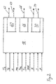
In der Darstellung der
Weiterhin stehen dem Steuergerät 18 als Eingangsgrößen eine Außenlufttemperatur TAL, eine Ladelufttemperatur TLL, eine Abgasrückführrate AGR, die bereits erwähnten Klimaanforderungen K, eine Fahrzeuggeschwindigkeit v sowie eine Fahrpedalstellung p zur Verfügung. Diese Eingangsgrößen werden dazu verwendet, einen Zustand des Systems aus Verbrennungsmotor 10 und Kühlmittelkreislauf zu bestimmen, wobei in den einzelnen Zuständen unterschiedliche Maßnahmen getroffen werden, um die Kühlmittel- und Bauteiltemperatur zu regeln. Nach Bestimmung des Systemszustands wird zur Regelung eine Kühlmittelvolumenstromanforderung bestimmt, die durch den Block 60 dargestellt ist. Die Volumenstromanforderung 60 wird in eine Stellgröße 62 für die Einstellung der Heizungspumpe 32 sowie eine Stellgröße 64 für die Einstellung der Kühlmittelpumpe 26 umgesetzt.Furthermore, the
Darüber hinaus wird eine Drehschieberpositionierung 66 angefordert, die in eine Stellgröße 68 für die Einstellung des Mischventils 14 umgesetzt wird.In addition, a rotary valve positioning 66 is requested, which is converted into a manipulated
Schließlich wird eine Kühlluftmassenanforderung 70 bestimmt, die in eine Stellgröße 72 zur Ansteuerung der Kühlerjalousie 40 sowie in eine Stellgröße 74 zur Ansteuerung des Lüfters 44 gesetzt wird.Finally, a cooling
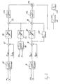
In der Darstellung der
Zur Ermittlung des Korrekturwerts wird durch einen Block 88 ein Sollwert TKsoll für die Kühlmitteltemperatur in Abhängigkeit der aktuellen Einspritzmenge me der aktuellen Motordrehzahl n vorgegeben. Der Sollwert TKsoll wird einer Verknüpfungseinheit 90 übergeben, der auch der aktuelle Istwert der Kühlmitteltemperatur TKIst vom Kühlmittelsensor 48 zur Verfügung steht und die aus diesen Werten eine Regeldifferenz ermittelt. Die so ermittelte Regeldifferenz wird an einen Block 92 übergeben, in dem auf die ermittelte Regeldifferenz eine Hysteresekennlinie angewendet wird. Vom Block 92 wird somit ein Korrekturwert für die Volumenstromanforderung an die Verknüpfungseinheit 84 übergeben und dort auf den zuvor ermittelten Grundwert aufaddiert.In order to determine the correction value, a setpoint T Ksoll for the coolant temperature as a function of the current injection quantity m e of the current engine speed n is specified by a
In ähnlicher Weise wird zur Berücksichtigung der Bauteiltemperatur TB in einem Block 94 anhand eines Grundkennfelds unter Berücksichtigung der Einspritzmenge me sowie der Motordrehzahl n zunächst ein Sollwert TBSoll ermittelt und in einer Verknüpfungseinheit 96 aus einem Istwert TBisc und dem Sollwert TBSoll eine Regeldifferenz ermittelt. Auf die ermittelte Regeldifferenz wird im Block 98 eine Hysteresekennlinie angewendet, so dass vom Block 98 ein Korrekturwert für eine Volumenstromanforderung an die Verknüpfungseinheit 86 übergeben wird. Parallel zur Anwendung der Hysteresekennlinie in Block 98 wird im Block 100 eine zeitliche Veränderung der Bauteiltemperatur berücksichtigt, um eine zufriedenstellende Regelung der im Vergleich zur Kühlmitteltemperatur dynamischeren Bauteiltemperatur zu erreichen. Auch die vom Block 100 ausgegebene Volumenstromanforderung wird der Verknüpfungseinheit 86 zugeführt.Similarly, to take into account the component temperature T B in a
Sowohl die Volumenstromanforderung aus dem Block 84 als auch die Volumenstromanforderung aus dem Block 86 werden in einem Block 102 bzw. 104 daraufhin geprüft, ob sie einen maximal bzw. minimal applizierbaren Wert überschreiten und gegebenenfalls auf diese Werte beschränkt.Both the volume flow request from
Von den Blöcken 102 und 104 werden die Volumenstromanforderungen daraufhin an eine Max-Verknüpfungseinheit 106 übergeben. In der Max-Verknüpfungseinheit 106 wird geprüft, welche der Volumenstromanforderungen vom Block 102 oder vom Block 104 größer ist, und lediglich die größere Volumenstromanforderung wird an einen Block 108 übergeben, in dem eine Umsetzungskennlinie auf die Volumenstromanforderung angewendet wird. Dadurch wird die Volumenstromanforderung in ein Ansteuersignal für die Kühlmittelpumpe 26 umgesetzt, das schließlich mittels einer Endstufe 110 verstärkt und an die Kühlmittelpumpe 26 weitergegeben wird.From the
Die Regelungsstruktur gemäß
Darüber hinaus können auch zusätzliche Anforderungen durch die in der
Wie im Zusammenhang mit der
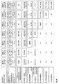
Diese sieben möglichen Zustände oder Stufen bei der erfindungsgemäßen Wärmemanagementregelung werden anhand der
Ein erster Zustand entspricht einem Kaltstart, bei dem eine Bauteiltemperatur im Bereich von -20°C bis 120°C und eine Kühlmitteltemperatur am Austritt aus dem Verbrennungsmotor im Bereich von -20°C bis 80°C liegt. Eine Temperatur der Ladeluft nach einem Ladeluftkühler ist kleiner als 60°C und ein Druck eines Kältemittels in einem Klimatisierungskreislauf liegt unterhalb von 12 bar. Beispielsweise liegen niedrige Umgebungstemperaturen im Bereich von -20°C vor. In diesem ersten Zustand ist die Zielsetzung, den Warmlauf des Verbrennungsmotors 10 zu beschleunigen und möglich schnell eine akzeptable Innenraumtemperatur zu erreichen. Hierzu wird der durch die Heizungspumpe 32 fließende Volumenstrom mittels des Motors 34 über die zentrale Steuereinheit 18 geregelt. Dadurch werden auch der Abgasrückführ-Wärmetauscher 36 sowie der Heizungs-Wärmetauscher 38 durchströmt, so dass eine rasche Erwärmung des Innenraums erwartet werden kann. Die Magnetkupplung 28 der Kühlmittelpumpe 26 ist entkoppelt, so dass die Kühlmittelpumpe 26 lediglich passiv durchströmt wird aber nicht selbst zur Förderung eines Volumenstroms beiträgt. Das Mischventil 14 ist im ersten Zustand so eingestellt, dass die Bypassleitung 18 vollständig geöffnet ist und die zum Kühler 22 führende Leitung vollständig geschlossen ist. Die Kühlerjalousie 40 ist vollständig geschlossen, der Lüfter 44 ausgeschaltet und auch ein Klimakompressor ist ausgeschaltet. Ein sogenannter Kochschutz, bei dessen Anwendung die Leistung des Verbrennungsmotors reduziert wird, um die anfallende Wärmemenge zu reduzieren, ist ausgeschaltet.A first state corresponds to a cold start in which a component temperature in the range of -20 ° C to 120 ° C and a coolant temperature at the exit from the internal combustion engine in the range of -20 ° C to 80 ° C. A temperature of the charge air after a charge air cooler is less than 60 ° C and a pressure of a refrigerant in an air conditioning circuit is below 12 bar. For example, are low Ambient temperatures in the range of -20 ° C. In this first state, the objective is to accelerate the warm-up of the
In einem zweiten Zustand, der wie der erste Zustand einem Warmlauf des Verbrennungsmotors zugeordnet ist und in dem eine Heizung des Innenraums erfolgen soll, ist das Kühlwasser sowie der Steg zwischen den Auslassventilen bereits erwärmt. Im einzelnen wird der Zustand des Systems vom Steuergerät 18 in den zweiten Zustand eingeordnet, wenn tiefe Umgebungstemperaturen, beispielsweise -20°C, eine Stegtemperatur im Bereich von 120°C bis 160°C, eine Temperatur am Kühlwasseraustritt 12 im Bereich von 80°C bis 90°C, eine Ladelufttemperatur nach dem Ladeluftkühler kleiner als 60°C und ein Kältemitteldruck von weniger als 12 bar vorliegen. In diesem zweiten Zustand ist, um den Innenraum möglichst schnell aufzuheizen, die Heizungspumpe 32 eingeschaltet und liefert 100% des möglichen Volumenstroms. Dadurch werden der Abgasrückführkühler 36 und der Heizungswärmetauscher 38 maximal durchströmt. Die Kühlmittelpumpe 26 wird durch wahlweises Ein- oder Ausschalten der Magnetkupplung zu- oder abgeschaltet. Dies erfolgt in Abhängigkeit der Kühlmittel- bzw. Stegtemperatur. Das Mischventil 14 ist im zweiten Zustand so eingestellt, dass die Bypassleitung 18 voll geöffnet und die zum Kühler 22 führende Leitung vollständig geschlossen ist. Die Kühlerjalousie 44 sowie gegebenenfalls weitere Jalousien vor dem Ladeluftkühler und einem Kondensator sind geschlossen. Der E-lektrolüfter 44, der Klimakompressor und der Kochschutz sind ausgeschaltet.In a second state, which is like the first state associated with a warm-up of the internal combustion engine and in which a heating of the interior is to take place, the cooling water and the web between the exhaust valves is already heated. In detail, the state of the system is classified by the
Ein Wechsel in einen dritten Zustand erfolgt dann, wenn der Verbrennungsmotor bereits betriebswarm ist und sich die Stegtemperatur und die Kühlmitteltemperatur im Sollbereich bewegen. Im dritten Zustand ist weiterhin eine Heizung im Fahrzeuginnenraum erforderlich. Im einzelnen nimmt das System den dritten Zustand ein, wenn tiefe Umgebungstemperaturen, beispielsweise -20°C, eine Stegtemperatur im Bereich von 140°C bis 180°C, eine Kühlmitteltemperatur am Austritt 12 im Bereich von 90°C bis 95°C, eine Ladelufttemperatur von weniger als 60°C und ein Kältemitteldruck von weniger als 12 bar vorliegen. In diesem dritten Zustand ist die Heizungspumpe 32 eingeschaltet und liefert 100% ihres möglichen Volumenstroms. Die Kühlmittelpumpe 26 ist zugeschaltet, da die Magnetkupplung 28 unbestromt ist. Das Mischventil 14 wird im Regelbetrieb gefahren und leitet infolgedessen den Kühlmittelstrom in Abhängigkeit von der Kühlmitteltemperatur am Kühlmittelsensor 48 und der Stegtemperatur am Bauteilsensor 50 durch die Bypassleitung 18 und/oder zum Kühler 22. Da das Mischventil 14 als Drehschieber ausgebildet ist, kann jede Verteilung des Kühlmittels auf die Bypassleitung 18 und den Kühler 22 im Regelbetrieb stufenlos eingestellt werden. Wie in den Zuständen eins und zwei sind die Kühlerjalousie 40 sowie gegebenenfalls weitere Jalousien geschlossen, der Lüfter 44, der Klimakompressor sowie ein Kochschutz sind ausgeschaltet.A change to a third state takes place when the internal combustion engine is already warm and the web temperature and the coolant temperature are in the desired range. In the third state, a heating in the vehicle interior is still required. In particular, the system assumes the third state when low ambient temperatures, for example -20 ° C, a web temperature in the range of 140 ° C to 180 ° C, a coolant temperature at the
Bei weiterer Erwärmung des Verbrennungsmotors 10 wird in einen vierten Zustand gewechselt, in dem die Betriebstemperaturen bereits am oberen Rand des Sollbereichs liegen. Auch in diesem vierten Zustand muss aufgrund tiefer Umgebungstemperaturen eine Heizung des Fahrzeuginnenraums erfolgen. Im einzelnen ist der vierte Zustand durch eine Stegtemperatur im Bereich von 160° bis 200°C, eine Kühlmitteltemperatur von 95°C bis 100°C, eine Ladelufttemperatur nach dem Ladeluftkühler von mehr als 60°C und einen Kältemitteldruck von weniger als 12 bar gekennzeichnet. In diesem vierten Zustand ist die Heizungspumpe 32 eingeschaltet und liefert 100% ihres möglichen Volumenstroms. Die Kühlmittelpumpe 26 ist, da die Magnetkupplung 28 unbestromt ist, zugeschaltet. Das Mischventil 14 nimmt eine Endstellung ein, verschließt die Bypassleitung 18 vollständig und leitet den Kühlmittelstrom vollständig zum Fahrzeugkühler 22. Die Kühlerjalousie 40 sowie gegebenenfalls weitere Jalousien werden in Abhängigkeit der Kühlmitteltemperatur und der Stegtemperatur geregelt. Der Lüfter 44, der Klimakompressor und der Kochschutz sind ausgeschaltet.Upon further heating of the
Das System wechselt in einen fünften Zustand, wenn höhere Umgebungstemperaturen, beispielsweise um 20°C, vorliegen, so dass keine Heizung im Fahrzeuginnenraum mehr erforderlich ist aber auch noch keine Klimatisierung nötig ist. Der fünfte Zustand ist im einzelnen durch Stegtemperaturen im Bereich von 160°C bis 200°C, Kühlmitteltemperaturen zwischen 100°C und 115°C, Ladelufttemperaturen von mehr als 60°C und einen Kältemitteldruck von weniger als 12 bar gekennzeichnet. Im fünften Zustand ist die Heizungspumpe 32 ausgeschaltet, die Kühlmittelpumpe 26 ist zugeschaltet und das Mischventil 14 verschließt die Bypassleitung 18 und leitet den Kühlmittelstrom vollständig zum Kühler 22. Die Kühlerjalousie 40 sowie gegebenenfalls weitere Jalousien vor dem Ladeluftkühler und dem Kondensator sind vollständig geöffnet. Der Lüfter 44 wird in Abhängigkeit der Kühlmitteltemperatur und der Stegtemperatur geregelt. Der Klimakompressor und der Kochschutz sind ausgeschaltet.The system changes to a fifth state when higher ambient temperatures, for example, around 20 ° C, so that no more heating in the vehicle interior is required but also no air conditioning is needed. The fifth state is characterized in detail by web temperatures in the range of 160 ° C to 200 ° C, coolant temperatures between 100 ° C and 115 ° C, charge air temperatures of more than 60 ° C and a refrigerant pressure of less than 12 bar. In the fifth state, the
Bei einem weiterem Anstieg der Umgebungstemperaturen wird eine Klimatisierung des Innenraums erforderlich und das System wechselt in einen sechsten Zustand. Im einzelnen ist der sechste Zustand durch Umgebungstemperaturen im Bereich von 20°C bis 30°C, Stegtemperaturen im Bereich von 160°C bis 200°C, Kühlmitteltemperaturen im Bereich von 100°C bis 115°C, Ladelufttemperaturen von mehr als 60°C und einen Kältemitteldruck im Bereich von 12 bar bis 20 bar gekennzeichnet. In diesem Zustand versucht das System noch alle Anforderungen bezüglich Motorleistung und Klimaleistung zu erfüllen und mobilisiert alle Reserven, die zur Wärmeabfuhr von dem Verbrennungsmotor 10 zur Verfügung stehen. Die Heizungspumpe 32 ist ausgeschaltet, die Kühlmittelpumpe 26 dahingegen wird zugeschaltet. Das Mischventil 14 hält die Bypassleitung 18 weiterhin verschlossen und leitet den Kühlmittelstrom vollständig zum Kühler 22. Die Kühlerjalousie 40 sowie gegebenenfalls weitere Jalousien sind vollständig geöffnet. Der Lüfter 44 läuft mit maximaler Leistung und ermöglicht dadurch einen maximalen Luftdurchsatz durch den Kühler 22. Der Klimakompressor wird in Abhängigkeit der gewünschten Innenraumtemperatur geregelt. Der Kochschutz ist ausgeschaltet.With a further increase in ambient temperatures, an air conditioning of the interior is required and the system changes to a sixth state. Specifically, the sixth state is ambient temperatures in the range of 20 ° C to 30 ° C, web temperatures in the range of 160 ° C to 200 ° C, coolant temperatures in the range of 100 ° C to 115 ° C, charge air temperatures greater than 60 ° C and a refrigerant pressure in the range of 12 bar to 20 bar. In this state, the system still attempts to meet all engine performance and climate performance requirements and mobilizes all of the reserves available for heat removal from the
Bei einem weiteren Anstieg der Umgebungstemperaturen und/oder ungünstigen Randbedingungen, wie hohe Motorleistung und geringer Fahrgeschwindigkeit, können die Betriebstemperaturen des Motors weiter und in den kritischen Bereich steigen. In diesem siebten Zustand müssen somit Maßnahmen getroffen werden, um den Verbrennungsmotor 10 vor thermischen Schäden zu bewahren. Im einzelnen ist der siebte Zustand durch eine hohe Umgebungstemperatur, beispielsweise zwischen 30°C und 35°C, eine Stegtemperatur im Bereich 160°C bis 200°C, eine Kühlmitteltemperatur im kritischen Bereich von mehr als 115°C, eine Ladelufttemperatur von mehr als 60°C und einen Kältemitteldruck von mehr als 20 bar gekennzeichnet. Sämtliche Reserven zur Wärmeabfuhr sind mobilisiert und die Heizungspumpe 32 ist ausgeschaltet, die Kühlmittelpumpe 26 zugeschaltet, das Mischventil verschließt die Bypassleitung 18 vollständig und leitete den Kühlmittelstrom vollständig zum Kühler 22, die Kühlerjalousie 40 sowie gegebenenfalls weitere Jalousien sind vollständig geöffnet und der Lüfter 44 läuft mit maximaler Leistung. Um einen weiteren Temperaturanstieg zu verhindern, wird der Klimakompressor mit reduzierter Leistung gefahren und gleichzeitig wird über den Kochschutz eine reduzierte Motorleistung eingestellt. Dies kann beispielsweise dadurch erfolgen, dass eine Einspritzmenge reduziert wird. Sinken die Betriebstemperaturen ab, kann das System wieder in den sechsten Zustand wechseln und die volle Motor- und Klimaleistung steht wieder zur Verfügung.With a further increase in ambient temperatures and / or unfavorable boundary conditions, such as high engine power and low driving speed, the operating temperatures of the engine can continue to rise and in the critical range. In this seventh state, therefore, measures must be taken to protect the
Sind nicht alle Randbedingungen für eine bestimmte Stufe oder einen bestimmten Zustand erfüllt, kann eine Priorisierung dahingehend erfolgen, dass das System einen bestimmten Zustand einnimmt, wenn ausgewählte Betriebsparameter innerhalb eines für diesen Zustand definierten Bereichs liegen.If all boundary conditions for a particular stage or condition are not met, prioritization can be made such that the system assumes a particular condition when selected operational parameters are within a range defined for that condition.
Claims (6)
- Method for regulating the heat of a system made up from an internal combustion engine and a coolant circuit of a vehicle with selectable devices of the coolant circuit, wherein a coolant temperature and further operating parameters of the internal combustion engine (10) are detected and the selectable devices (14, 26, 32, 40, 44) are selected in dependence on the coolant temperature and on the further operating parameters of the internal combustion engine (10), wherein the coolant temperature is regulated such that an initial value is preset for the determination of a control variable by means of a basic characteristic map (80) in dependence on the speed and the load of the internal combustion engine and this initial value is corrected by means of a controller in dependence on coolant temperature and/or on the further operating parameters,
characterised in that, using at least two different command variables (TK, TB), at least two initial values are determined for the determination of a control variable for the selectable devices (14, 26, 32, 40, 44), in that the at least two initial values are compared and in that the higher initial value is converted into the control variable and transmitted to the selectable devices (14, 26, 32, 40, 44). - Method according to claim 1,
characterised in that
the coolant temperature and the further operating parameters are regulated such that an initial value for the determination of a control variable by means of a basic characteristic map (80) is preset in dependence on the speed and the load of the internal combustion engine, and in that this initial value is corrected by means of a controller in dependence on coolant temperature and/or on the further operating parameters. - Method according to claim 1 or 2,
characterised in that
a hysteresis characteristic (82, 92, 98) is used in the determination of a control variable. - Method according to any of the preceding claims,
characterised in that
set values for a coolant temperature (TKsoll) and a component temperature (TBsoll) of the internal combustion engine are determined by means of characteristic maps (88, 94) in dependence on a speed and an injected fuel amount of the internal combustion engine (10). - Method according to any of the preceding claims,
characterised in that
several states of the system made up from the internal combustion engine (10) and the coolant circuit are defined, each of which is assigned to different values of coolant temperature and/or of the further operating parameters, and in which the selectable devices (14, 26, 32, 40, 44) for controlling at least the coolant temperature are at least partially selected in different ways. - Method according to any of the preceding claims,
characterised in that
a change to the various states is triggered by exceeding or falling short of preset limit values of an ambient temperature, a component temperature of the internal combustion engine, a coolant temperature, a charge air temperature and/or a pressure of an air conditioning compressor, and in that in the individual states the settings of a coolant pump (26), a heater pump (32), a mixing valve (14) between a radiator circuit and a bypass circuit, a radiator grille (40), a radiator fan (44), an air conditioning compressor and/or an injection system of the internal combustion engine (10) are changed to control a coolant temperature and/or a component temperature of the internal combustion engine (10).
Applications Claiming Priority (3)
| Application Number | Priority Date | Filing Date | Title |
|---|---|---|---|
| DE10224063A DE10224063A1 (en) | 2002-05-31 | 2002-05-31 | Method for heat regulation of an internal combustion engine for vehicles |
| DE10224063 | 2002-05-31 | ||
| PCT/EP2003/003301 WO2003102394A1 (en) | 2002-05-31 | 2003-03-29 | Method for regulating the heat of an internal combustion engine for vehicles |
Publications (2)
| Publication Number | Publication Date |
|---|---|
| EP1509687A1 EP1509687A1 (en) | 2005-03-02 |
| EP1509687B1 true EP1509687B1 (en) | 2010-09-01 |
Family
ID=29432461
Family Applications (1)
| Application Number | Title | Priority Date | Filing Date |
|---|---|---|---|
| EP03714903A Expired - Fee Related EP1509687B1 (en) | 2002-05-31 | 2003-03-29 | Method for regulating the heat of an internal combustion engine for vehicles |
Country Status (5)
| Country | Link |
|---|---|
| US (1) | US7128026B2 (en) |
| EP (1) | EP1509687B1 (en) |
| JP (1) | JP4164690B2 (en) |
| DE (2) | DE10224063A1 (en) |
| WO (1) | WO2003102394A1 (en) |
Families Citing this family (68)
| Publication number | Priority date | Publication date | Assignee | Title |
|---|---|---|---|---|
| DE10336599B4 (en) * | 2003-08-08 | 2016-08-04 | Daimler Ag | Method for controlling a thermostat in a cooling circuit of an internal combustion engine |
| DE102004006591A1 (en) * | 2004-02-10 | 2005-08-25 | Behr Gmbh & Co. Kg | Heating arrangement and method for heating control |
| WO2005125295A2 (en) * | 2004-06-17 | 2005-12-29 | Avl List Gmbh | Device for cooling at least one electrical and/or electronic power component |
| DE102004034066B4 (en) * | 2004-07-15 | 2012-10-31 | Bayerische Motoren Werke Aktiengesellschaft | Device for controlling the cooling of an internal combustion engine for motor vehicles |
| DE102004059004A1 (en) * | 2004-12-08 | 2006-06-14 | Daimlerchrysler Ag | Heating operation of an internal combustion engine |
| ATE454543T1 (en) * | 2004-12-23 | 2010-01-15 | Valeo Thermique Moteur Sa | SYSTEM FOR CONTROLLING THE THERMAL ENERGY OF A MOTOR VEHICLE ENGINE BY ADJUSTING THE SYSTEM'S FLUID DRIVES |
| FR2890700B1 (en) * | 2005-09-13 | 2007-11-02 | Renault Sas | MOTOR VEHICLE COMPRISING RECIRCULATED GAS CIRCUIT COOLED AT LOW TEMPERATURE |
| US20090020079A1 (en) * | 2005-11-10 | 2009-01-22 | BEHRmbH & Co. KG | Circulation system, mixing element |
| US7409928B2 (en) * | 2006-01-27 | 2008-08-12 | Gm Global Technology Operations, Inc. | Method for designing an engine component temperature estimator |
| KR101420887B1 (en) | 2006-05-08 | 2014-07-17 | 마그나 파워트레인 인크. | Vehicle cooling system with directed flows |
| GB2442742A (en) * | 2006-10-12 | 2008-04-16 | Ford Global Tech Llc | Cooling system for an internal combustion engine comprising an exhaust gas cooler |
| US8430068B2 (en) * | 2007-05-31 | 2013-04-30 | James Wallace Harris | Cooling system having inlet control and outlet regulation |
| EP2096276A1 (en) * | 2008-02-28 | 2009-09-02 | Behr GmbH & Co. KG | Method for the control of an engine supercharging system, control system, computer programm product, storage medium and an engine supercharging system |
| DE102008052014A1 (en) | 2008-10-17 | 2010-04-22 | Daimler Ag | Heat exchanger arrangement for vehicle, has radiator for cooling internal combustion engine, and heating heat exchanger |
| US20100114463A1 (en) * | 2008-10-30 | 2010-05-06 | Caterpillar Inc. | System for cold starting machine |
| DE202009003807U1 (en) | 2009-03-20 | 2010-08-12 | Voss Automotive Gmbh | Electric heating system for a fluid line system |
| US8256387B2 (en) * | 2009-04-28 | 2012-09-04 | Denso International America, Inc. | Radiator shutter using film door technology |
| DE102009054783B4 (en) * | 2009-12-16 | 2017-06-01 | Ford Global Technologies, Llc | A method of performing temperature management in a cooling system based on a matrix controller |
| DE102009058585A1 (en) * | 2009-12-17 | 2011-06-22 | Bayerische Motoren Werke Aktiengesellschaft, 80809 | Cooling arrangement for a motor vehicle internal combustion engine and method for operating the same |
| DE102010002605B4 (en) * | 2010-03-05 | 2013-12-12 | Ford Global Technologies, Llc | Method for shortening the warm-up phase by means of heat recovery from recirculated exhaust gases |
| DE102010010624A1 (en) * | 2010-03-09 | 2011-09-15 | GM Global Technology Operations LLC , (n. d. Ges. d. Staates Delaware) | Coaxial heat exchanger for a motor vehicle exhaust system |
| KR20110120766A (en) * | 2010-04-29 | 2011-11-04 | 현대자동차주식회사 | Apparatus for control water pump of hybrid vehicle and method thereof |
| FR2961264B1 (en) * | 2010-06-09 | 2015-10-09 | Peugeot Citroen Automobiles Sa | METHOD FOR CONTROLLING THE COMBUSTION OF A THERMAL MOTOR AND METHOD FOR DETECTING A DYSFUNCTION OF SAID MOTOR |
| US20120097464A1 (en) * | 2010-10-22 | 2012-04-26 | Gm Global Technology Operations, Inc. | Control of a shutter via bi-directional communication using a single wire |
| US8689917B2 (en) | 2010-10-22 | 2014-04-08 | GM Global Technology Operations LLC | Method for monitoring operation of a shutter |
| JP5500264B2 (en) * | 2010-11-01 | 2014-05-21 | トヨタ自動車株式会社 | Internal combustion engine cooling system |
| DE102010060319B4 (en) * | 2010-11-03 | 2012-05-31 | Ford Global Technologies, Llc. | cooling system |
| US8443921B2 (en) * | 2010-11-09 | 2013-05-21 | GM Global Technology Operations LLC | System and method for increasing operating efficiency of a powertrain by controlling an aero shutter |
| KR20120060508A (en) * | 2010-12-02 | 2012-06-12 | 현대자동차주식회사 | Control Method for Electric Thermostat and Control Apparatus thereof |
| DE102011004327A1 (en) * | 2011-02-17 | 2012-08-23 | Siemens Aktiengesellschaft | Method for operating a rail vehicle |
| DE102011108953B4 (en) * | 2011-07-29 | 2014-11-27 | Audi Ag | Coolant circuit for an internal combustion engine and method for operating a coolant circuit |
| US9416720B2 (en) | 2011-12-01 | 2016-08-16 | Paccar Inc | Systems and methods for controlling a variable speed water pump |
| DE102012200003B4 (en) * | 2012-01-02 | 2015-04-30 | Ford Global Technologies, Llc | Liquid-cooled internal combustion engine and method for operating such an internal combustion engine |
| DE102012200746A1 (en) * | 2012-01-19 | 2013-07-25 | Ford Global Technologies, Llc | Internal combustion engine having a pump arranged in the coolant circuit and method for operating such an internal combustion engine |
| JP5892469B2 (en) * | 2012-03-09 | 2016-03-23 | スズキ株式会社 | Cooling device for internal combustion engine for vehicle |
| US8997483B2 (en) * | 2012-05-21 | 2015-04-07 | GM Global Technology Operations LLC | Engine thermal management system and method for split cooling and integrated exhaust manifold applications |
| US9657632B2 (en) | 2012-08-01 | 2017-05-23 | GM Global Technology Operations LLC | Method and apparatus for remote torque control of an aerodynamic air shutter mechanism |
| FR3001797A1 (en) * | 2013-02-06 | 2014-08-08 | Peugeot Citroen Automobiles Sa | Method for cooling and protecting air/fluid heat exchanger equipped in car, involves protecting air/fluid heat exchanger against nucleate boiling of coolant i.e. water glycol mixture flowing into air/fluid heat exchanger |
| US9394858B2 (en) * | 2013-03-11 | 2016-07-19 | Ford Global Technologies, Llc | Charge air cooling control for boosted engines to actively maintain targeted intake manifold air temperature |
| US9115635B2 (en) | 2013-03-22 | 2015-08-25 | Ford Global Technologies, Llc | Inferred engine local temperature estimator |
| FR3008175A1 (en) * | 2013-07-04 | 2015-01-09 | Valeo Systemes Thermiques | DEVICE FOR CONTROLLING THE CIRCULATION OF A COOLANT FOR A HEAT EXCHANGER, PARTICULARLY A MOTOR VEHICLE MOTOR VEHICLE SUPERCORDITION AIR COOLER |
| US20150041229A1 (en) * | 2013-08-08 | 2015-02-12 | Honda Motor Co., Ltd. | Front end arrangement with active radiator damper and active radiator control method |
| DE102013219144B4 (en) * | 2013-09-24 | 2022-02-03 | Bayerische Motoren Werke Aktiengesellschaft | Heat management system for motor vehicles |
| JP6201888B2 (en) * | 2014-05-14 | 2017-09-27 | トヨタ自動車株式会社 | Cooling device for internal combustion engine |
| FR3022591B1 (en) * | 2014-06-20 | 2016-06-10 | Renault Sa | METHOD FOR CONTROLLING AN INTERNAL COMBUSTION ENGINE |
| DE102014015638A1 (en) * | 2014-10-22 | 2016-04-28 | GM Global Technology Operations LLC (n. d. Gesetzen des Staates Delaware) | Controlling a coolant pump and / or a control valve of a cooling system for a ... |
| JP6072752B2 (en) | 2014-11-12 | 2017-02-01 | 本田技研工業株式会社 | Cooling control device for internal combustion engine |
| GB2535159A (en) * | 2015-02-09 | 2016-08-17 | Gm Global Tech Operations Llc | Method of controlling a cooling circuit of an internal combustion engine |
| EP3056706A1 (en) | 2015-02-16 | 2016-08-17 | Honeywell International Inc. | An approach for aftertreatment system modeling and model identification |
| EP3734375B1 (en) | 2015-07-31 | 2023-04-05 | Garrett Transportation I Inc. | Quadratic program solver for mpc using variable ordering |
| US10272779B2 (en) | 2015-08-05 | 2019-04-30 | Garrett Transportation I Inc. | System and approach for dynamic vehicle speed optimization |
| DE102015117592A1 (en) | 2015-10-15 | 2017-04-20 | Volkswagen Aktiengesellschaft | Controlling a coolant pump in a charging gas cooling circuit |
| KR101807046B1 (en) * | 2016-04-01 | 2017-12-08 | 현대자동차 주식회사 | Engine cooling system having coolant temperautre sensor |
| US10728249B2 (en) | 2016-04-26 | 2020-07-28 | Garrett Transporation I Inc. | Approach for securing a vehicle access port |
| US10124750B2 (en) | 2016-04-26 | 2018-11-13 | Honeywell International Inc. | Vehicle security module system |
| US10036338B2 (en) * | 2016-04-26 | 2018-07-31 | Honeywell International Inc. | Condition-based powertrain control system |
| EP3548729B1 (en) | 2016-11-29 | 2023-02-22 | Garrett Transportation I Inc. | An inferential flow sensor |
| JP6589906B2 (en) * | 2017-02-16 | 2019-10-16 | トヨタ自動車株式会社 | Control device for internal combustion engine |
| DE102017202638B4 (en) | 2017-02-20 | 2022-04-28 | Ford Global Technologies, Llc | Predictive thermal management for motor vehicles |
| US20190010858A1 (en) | 2017-07-10 | 2019-01-10 | GM Global Technology Operations LLC | Controlling engine coolant fluid temperature |
| DE102017123468A1 (en) | 2017-10-10 | 2019-04-11 | Volkswagen Aktiengesellschaft | Method for operating an internal combustion engine, internal combustion engine and motor vehicle |
| US11057213B2 (en) | 2017-10-13 | 2021-07-06 | Garrett Transportation I, Inc. | Authentication system for electronic control unit on a bus |
| DE102018104409A1 (en) * | 2018-02-27 | 2019-08-29 | Volkswagen Aktiengesellschaft | Cooling system and internal combustion engine |
| KR102496812B1 (en) * | 2018-08-06 | 2023-02-06 | 현대자동차 주식회사 | Control method of cooling system |
| DE102019208959A1 (en) * | 2019-06-19 | 2020-12-24 | Volkswagen Aktiengesellschaft | Internal combustion engine with a cooling system comprising an EGR cooler |
| DE102020128706B4 (en) | 2020-11-02 | 2023-06-15 | Dr. Ing. H.C. F. Porsche Aktiengesellschaft | Method and control for regulating a fan of a cooling device of an internal combustion engine of a motor vehicle |
| US11578642B1 (en) | 2021-08-05 | 2023-02-14 | Garrett Transportation I Inc. | Thermostat leak detection |
| CN113969820A (en) * | 2021-11-01 | 2022-01-25 | 郭福海 | Engine intelligent thermal management system with ambient temperature monitoring function |
Citations (2)
| Publication number | Priority date | Publication date | Assignee | Title |
|---|---|---|---|---|
| DE3231766A1 (en) * | 1982-08-26 | 1984-03-01 | Robert Bosch Gmbh, 7000 Stuttgart | DEVICE FOR REGULATING THE IDLE SPEED IN AN INTERNAL COMBUSTION ENGINE |
| EP0152604A1 (en) * | 1984-02-01 | 1985-08-28 | Robert Bosch Gmbh | Control and regulation method for the operating parameters of an internal-combustion engine |
Family Cites Families (24)
| Publication number | Priority date | Publication date | Assignee | Title |
|---|---|---|---|---|
| DE3024209A1 (en) * | 1979-07-02 | 1981-01-22 | Guenter Dr Rinnerthaler | Liq. cooling system for automobile engine with electronic control - regulating circulation pump or variable selective blocking element and by=pass line |
| US4489680A (en) * | 1984-01-23 | 1984-12-25 | Borg-Warner Corporation | Engine temperature control system |
| US4549504A (en) * | 1984-07-19 | 1985-10-29 | Evans Products Company | Electronic controller for regulating temperature within an internal combustion engine system |
| US4930455A (en) * | 1986-07-07 | 1990-06-05 | Eaton Corporation | Controlling engine coolant flow and valve assembly therefor |
| DE3625375A1 (en) * | 1986-07-26 | 1988-02-04 | Porsche Ag | COOLING FLAP AND BLOWER CONTROL FOR MOTOR VEHICLES |
| DE3810174C2 (en) * | 1988-03-25 | 1996-09-19 | Hella Kg Hueck & Co | Device for regulating the coolant temperature of an internal combustion engine, in particular in motor vehicles |
| DE69325044T2 (en) * | 1992-02-19 | 1999-09-30 | Honda Motor Co Ltd | Machine cooling system |
| ES2112717B1 (en) * | 1993-07-19 | 1998-12-01 | Bayerische Motoren Werke Ag | COOLING ARRANGEMENT FOR AN INTERNAL COMBUSTION ENGINE OF AN AUTOMOBILE. |
| DE4324178A1 (en) * | 1993-07-19 | 1995-01-26 | Bayerische Motoren Werke Ag | Cooling system for an internal combustion engine of a motor vehicle with a thermostatic valve that contains an electrically heated expansion element |
| DE4337717A1 (en) * | 1993-11-05 | 1995-05-11 | Graf Peter Von Ingelheim | Control device for cooling circuits of internal combustion engines with throttle valves or directional control valves which can assume two positions |
| DE19500648B4 (en) * | 1995-01-12 | 2010-12-30 | Behr Thermot-Tronik Gmbh | Cooling system for an internal combustion engine of a motor vehicle with a thermostatic valve |
| DE19508104C2 (en) * | 1995-03-08 | 2000-05-25 | Volkswagen Ag | Method for regulating a cooling circuit of an internal combustion engine |
| DE19719792B4 (en) * | 1997-05-10 | 2004-03-25 | Behr Gmbh & Co. | Method and device for regulating the temperature of a medium |
| EP0889211B1 (en) * | 1997-07-02 | 2006-09-13 | Nippon Thermostat Co., Ltd. | Cooling control system and cooling control method for engine |
| DE19728351B4 (en) | 1997-07-03 | 2004-07-22 | Daimlerchrysler Ag | Method for thermoregulation of an internal combustion engine |
| DE19939138A1 (en) * | 1999-08-18 | 2001-02-22 | Bosch Gmbh Robert | Method for regulating the temperature of the coolant of an internal combustion engine by means of an electrically operated coolant pump |
| DE19951362A1 (en) * | 1999-10-26 | 2001-05-03 | Bosch Gmbh Robert | Method for regulating the cooling water temperature of a motor vehicle with an internal combustion engine |
| US6352055B1 (en) * | 1999-11-24 | 2002-03-05 | Caterpillar Inc. | Engine water pump control system |
| JP4337207B2 (en) * | 2000-02-10 | 2009-09-30 | 株式会社デンソー | Cooling device for liquid-cooled internal combustion engine |
| DE10016405A1 (en) * | 2000-04-01 | 2001-10-11 | Bosch Gmbh Robert | Cooling circuit |
| JP2002222018A (en) * | 2001-01-26 | 2002-08-09 | Honda Motor Co Ltd | Supply controller for working medium in heat exchanger |
| DE10155339A1 (en) * | 2001-11-10 | 2003-05-22 | Daimler Chrysler Ag | Method for operating an internal combustion engine and motor vehicle |
| DE50111700D1 (en) * | 2001-11-30 | 2007-02-01 | Borgwarner Inc | Control for a fan of a cooling system of an internal combustion engine |
| JP4241211B2 (en) * | 2003-06-19 | 2009-03-18 | トヨタ自動車株式会社 | Secondary air supply device |
-
2002
- 2002-05-31 DE DE10224063A patent/DE10224063A1/en not_active Withdrawn
-
2003
- 2003-03-29 EP EP03714903A patent/EP1509687B1/en not_active Expired - Fee Related
- 2003-03-29 JP JP2004509255A patent/JP4164690B2/en not_active Expired - Fee Related
- 2003-03-29 DE DE50313040T patent/DE50313040D1/en not_active Expired - Lifetime
- 2003-03-29 WO PCT/EP2003/003301 patent/WO2003102394A1/en active Application Filing
-
2004
- 2004-11-27 US US10/998,355 patent/US7128026B2/en not_active Expired - Fee Related
Patent Citations (2)
| Publication number | Priority date | Publication date | Assignee | Title |
|---|---|---|---|---|
| DE3231766A1 (en) * | 1982-08-26 | 1984-03-01 | Robert Bosch Gmbh, 7000 Stuttgart | DEVICE FOR REGULATING THE IDLE SPEED IN AN INTERNAL COMBUSTION ENGINE |
| EP0152604A1 (en) * | 1984-02-01 | 1985-08-28 | Robert Bosch Gmbh | Control and regulation method for the operating parameters of an internal-combustion engine |
Also Published As
| Publication number | Publication date |
|---|---|
| US7128026B2 (en) | 2006-10-31 |
| DE50313040D1 (en) | 2010-10-14 |
| DE10224063A1 (en) | 2003-12-11 |
| WO2003102394A1 (en) | 2003-12-11 |
| JP2005529269A (en) | 2005-09-29 |
| EP1509687A1 (en) | 2005-03-02 |
| JP4164690B2 (en) | 2008-10-15 |
| US20060005790A1 (en) | 2006-01-12 |
Similar Documents
| Publication | Publication Date | Title |
|---|---|---|
| EP1509687B1 (en) | Method for regulating the heat of an internal combustion engine for vehicles | |
| EP0744539B1 (en) | Cooling system with an electrically controlled actuator | |
| DE69925671T2 (en) | Control system for total cooling of an internal combustion engine | |
| EP1947308B1 (en) | Integrated motor cooling system | |
| DE3440504C2 (en) | ||
| DE10155339A1 (en) | Method for operating an internal combustion engine and motor vehicle | |
| DE112017003025B4 (en) | Cooling device for an internal combustion engine of a vehicle and its control method | |
| DE102007056360B4 (en) | Method for controlling an internal combustion engine | |
| EP1319815A2 (en) | Cooling circuit of a liquid cooled internal combustion engine | |
| DE3608417A1 (en) | IDLE SPEED CONTROL SYSTEM FOR A MOTOR VEHICLE INTERNAL COMBUSTION ENGINE | |
| DE102012202531A1 (en) | Cooling system for an internal combustion engine | |
| DE102005056638A1 (en) | Cooling system for a motor vehicle engine | |
| DE4324178A1 (en) | Cooling system for an internal combustion engine of a motor vehicle with a thermostatic valve that contains an electrically heated expansion element | |
| EP1461517B1 (en) | Method for controlling electrically-operated components of a cooling system, computer programme, controller, cooling system and internal combustion engine | |
| EP1454039B1 (en) | Method for the temperature regulation of an engine | |
| EP2530273B1 (en) | Construction machine with automatic ventilator rotation speed regulator | |
| DE102006008826B4 (en) | Thermal de-throttling in supercharged combustion engines | |
| DE10319762A1 (en) | Charge air cooling circuit and method of operating such a circuit | |
| DE10328786B4 (en) | Method for operating a motor vehicle | |
| DE10143091A1 (en) | Operation of vehicle heating and cooling circuit in conjunction with exhaust gas recycle system, controls exhaust enthalpy and coolant flow rates | |
| DE10228355A1 (en) | Internal combustion engine heat regulation involves controlling influencing devices according to prevailing state associated with certain coolant temperatures and/or other operating parameter values | |
| EP1461516B1 (en) | Method for controlling electrically-operated components of a cooling system, computer programme, controller, cooling system and internal combustion engine | |
| DE19519378A1 (en) | Cooling system with electrically adjustable actuator | |
| WO2005017327A1 (en) | Method for triggering a thermostat | |
| EP1523612B1 (en) | Method and device for regulating the temperature of a coolant in an internal combustion engine |
Legal Events
| Date | Code | Title | Description |
|---|---|---|---|
| PUAI | Public reference made under article 153(3) epc to a published international application that has entered the european phase |
Free format text: ORIGINAL CODE: 0009012 |
|
| 17P | Request for examination filed |
Effective date: 20041124 |
|
| AK | Designated contracting states |
Kind code of ref document: A1 Designated state(s): AT BE BG CH CY CZ DE DK EE ES FI FR GB GR HU IE IT LI LU MC NL PT RO SE SI SK TR |
|
| RBV | Designated contracting states (corrected) |
Designated state(s): DE FR GB IT |
|
| RAP1 | Party data changed (applicant data changed or rights of an application transferred) |
Owner name: DAIMLERCHRYSLER AG |
|
| 17Q | First examination report despatched |
Effective date: 20071108 |
|
| RAP1 | Party data changed (applicant data changed or rights of an application transferred) |
Owner name: DAIMLER AG |
|
| GRAP | Despatch of communication of intention to grant a patent |
Free format text: ORIGINAL CODE: EPIDOSNIGR1 |
|
| GRAS | Grant fee paid |
Free format text: ORIGINAL CODE: EPIDOSNIGR3 |
|
| GRAA | (expected) grant |
Free format text: ORIGINAL CODE: 0009210 |
|
| AK | Designated contracting states |
Kind code of ref document: B1 Designated state(s): DE FR GB IT |
|
| REG | Reference to a national code |
Ref country code: GB Ref legal event code: FG4D Free format text: NOT ENGLISH |
|
| REF | Corresponds to: |
Ref document number: 50313040 Country of ref document: DE Date of ref document: 20101014 Kind code of ref document: P |
|
| PG25 | Lapsed in a contracting state [announced via postgrant information from national office to epo] |
Ref country code: IT Free format text: LAPSE BECAUSE OF FAILURE TO SUBMIT A TRANSLATION OF THE DESCRIPTION OR TO PAY THE FEE WITHIN THE PRESCRIBED TIME-LIMIT Effective date: 20100901 |
|
| PLBE | No opposition filed within time limit |
Free format text: ORIGINAL CODE: 0009261 |
|
| STAA | Information on the status of an ep patent application or granted ep patent |
Free format text: STATUS: NO OPPOSITION FILED WITHIN TIME LIMIT |
|
| 26N | No opposition filed |
Effective date: 20110606 |
|
| REG | Reference to a national code |
Ref country code: DE Ref legal event code: R097 Ref document number: 50313040 Country of ref document: DE Effective date: 20110606 |
|
| REG | Reference to a national code |
Ref country code: FR Ref legal event code: PLFP Year of fee payment: 14 |
|
| REG | Reference to a national code |
Ref country code: FR Ref legal event code: PLFP Year of fee payment: 15 |
|
| PGFP | Annual fee paid to national office [announced via postgrant information from national office to epo] |
Ref country code: FR Payment date: 20170327 Year of fee payment: 15 |
|
| PGFP | Annual fee paid to national office [announced via postgrant information from national office to epo] |
Ref country code: GB Payment date: 20170330 Year of fee payment: 15 |
|
| PGFP | Annual fee paid to national office [announced via postgrant information from national office to epo] |
Ref country code: DE Payment date: 20170531 Year of fee payment: 15 |
|
| REG | Reference to a national code |
Ref country code: DE Ref legal event code: R119 Ref document number: 50313040 Country of ref document: DE |
|
| GBPC | Gb: european patent ceased through non-payment of renewal fee |
Effective date: 20180329 |
|
| PG25 | Lapsed in a contracting state [announced via postgrant information from national office to epo] |
Ref country code: DE Free format text: LAPSE BECAUSE OF NON-PAYMENT OF DUE FEES Effective date: 20181002 |
|
| PG25 | Lapsed in a contracting state [announced via postgrant information from national office to epo] |
Ref country code: GB Free format text: LAPSE BECAUSE OF NON-PAYMENT OF DUE FEES Effective date: 20180329 |
|
| PG25 | Lapsed in a contracting state [announced via postgrant information from national office to epo] |
Ref country code: FR Free format text: LAPSE BECAUSE OF NON-PAYMENT OF DUE FEES Effective date: 20180331 |