EP1524259A1 - Verfahren zur Herstellung von aromatischen Aminen durch heterogen katalysierte Hydrierung - Google Patents
Verfahren zur Herstellung von aromatischen Aminen durch heterogen katalysierte Hydrierung Download PDFInfo
- Publication number
- EP1524259A1 EP1524259A1 EP04023292A EP04023292A EP1524259A1 EP 1524259 A1 EP1524259 A1 EP 1524259A1 EP 04023292 A EP04023292 A EP 04023292A EP 04023292 A EP04023292 A EP 04023292A EP 1524259 A1 EP1524259 A1 EP 1524259A1
- Authority
- EP
- European Patent Office
- Prior art keywords
- catalyst
- catalytically active
- monolithic
- reactor
- bed
- Prior art date
- Legal status (The legal status is an assumption and is not a legal conclusion. Google has not performed a legal analysis and makes no representation as to the accuracy of the status listed.)
- Granted
Links
Classifications
-
- C—CHEMISTRY; METALLURGY
- C07—ORGANIC CHEMISTRY
- C07C—ACYCLIC OR CARBOCYCLIC COMPOUNDS
- C07C209/00—Preparation of compounds containing amino groups bound to a carbon skeleton
- C07C209/30—Preparation of compounds containing amino groups bound to a carbon skeleton by reduction of nitrogen-to-oxygen or nitrogen-to-nitrogen bonds
- C07C209/32—Preparation of compounds containing amino groups bound to a carbon skeleton by reduction of nitrogen-to-oxygen or nitrogen-to-nitrogen bonds by reduction of nitro groups
- C07C209/36—Preparation of compounds containing amino groups bound to a carbon skeleton by reduction of nitrogen-to-oxygen or nitrogen-to-nitrogen bonds by reduction of nitro groups by reduction of nitro groups bound to carbon atoms of six-membered aromatic rings in presence of hydrogen-containing gases and a catalyst
Definitions
- the invention relates to a process for the preparation of aromatic amines by catalytic Hydrogenation of aromatic nitro compounds.
- Aromatic amines are important intermediates that are inexpensive and produced in large quantities Need to become. Therefore, production plants for aromatic amines are usually for built very large capacities.
- the hydrogenation of nitroaromatics is a highly exothermic reaction. The removal and energetic use of the heat of reaction is therefore an important aspect in the production of nitroaromatics.
- DE-A 28 49 002 describes a process for the reduction of nitro compounds in the presence of stationary, palladium-containing multicomponent supported catalysts in cooled shell-and-tube reactors.
- the contact consists essentially of 1 to 20 g of palladium, 1 to 20 g of vanadium and 1 to 20 g of lead per liter of ⁇ -Al 2 O 3 . It has proved to be advantageous if the active components are deposited as close as possible to the surface of the catalyst in a very sharp zone and no active components are contained in the interior of the carrier material.
- a disadvantage of the gas-phase hydrogenation described in DE-A 28 49 002 is the low specific loading of the catalysts. The stated loads are about 0.4 to 0.5 kg / (1 ⁇ h).
- the load is defined as the amount of nitroaromatics in kg, which is enforced per liter of catalyst bed within one hour.
- the load is defined as the amount of nitroaromatics in kg, which is enforced per liter of catalyst bed within one hour.
- the selectivities at the beginning of a driving period are significantly lower than towards the end, which leads to yield losses and problems in the workup of the crude product.
- WO 98/25881 is the use of inert materials to dilute the catalyst bed during manufacture of aromatic amines.
- the dilution makes the reaction zone widened and thus increases the available surface area for heat exchange. With this procedure can be lowered the hot spot temperature or the possible nitroaromatic load be increased at a constant hot spot temperature. By dilution However, the service life of the bed decreases.
- the productivity of the diluted bed was due to the short service life despite higher load well below the productivity of the undiluted bed.
- the hydrogenation of nitroaromatics is thermostated Tube bundle reactors carried out.
- GB-A 1 452 466 discloses a process for the preparation of aniline in a thermostated shell and tube reactor using a supported copper catalyst described. To complete sales there is a catalyst bed as adiabater Used afterreactor.
- DE-A 199 31 902 describes a process for the preparation of monolithic oxidation catalysts and their use in the gas phase oxidation of hydrocarbons.
- a monolithic honeycomb catalyst is operated isothermally as an adiabatic reactor Downstream main reactor.
- the object of the present invention is to provide a process for the preparation of aromatic Amines by catalytic hydrogenation of aromatic nitro compounds available to provide, which is feasible on an industrial scale and compared to those from the Known prior art, carried out in tube bundle reactors a higher Space-time yield and longer life allows.
- the object of the invention is a process for the preparation of aromatic amines by catalytic hydrogenation of aromatic nitro compounds, which is characterized is that the catalytic hydrogenation is carried out at least one stage and the catalyst consists of at least one monolithic carrier and a catalytically active coating.
- monolith as used in the context of the present invention, is used e.g. in "Monoliths in multiphase catalytic processes - aspects and prospects" by F. Kapteijn, J.J. Heiszwolf, T.A. Nijhuis and J.A. Moulijn, Cattech 3, 1999, p. 24. After that you understand Under monoliths not only the “classical” carrier bodies with parallel, radial not with each other connected channels. It also includes foams, sponges or the like. with three-dimensional Compounds within the carrier body to the monoliths and carrier bodies with cross-flow channels.
- the low-pressure, monolithic carrier can be a honeycomb, but also an open or have closed cross-channel structure.
- the monolithic carrier has a preferred Cell density of 100 to 900 cpsi (cells per square inch), more preferably from 200 to 600 cpsi.
- Suitable materials for the monolithic carrier are ceramics such as e.g. Cordierite, silicates, silica, silicon carbide, alumina, aluminates, mullites or Mixtures of these substances as well as metals and metal alloys.
- the monolithic support can be provided with common, known from the prior art method with a catalytically active coating.
- a method is used for coating, which is referred to as dip-coating.
- the process is described, for example, in "Preparation of monolithic catalysts" by TA Nijhuis, AEW Beers, T. Vergunst, I. Hoek, F. Kapteijn and JA Moulijn in Catalysis Reviews, Vol. 43, 2001, pages 345-380.
- the monolithic carrier is coated with a suspension which is based on a very finely ground, Al 2 O 3 -supported catalytically active component.
- the catalytically active coating for the hydrogenation of aromatic nitro compounds in the gas phase preferably contains metals from groups VIIIa, Ib, IIb, IVa, Va, VIa, IVb and Vb of the Periodic Table of the Elements (Mendeleyev) as the catalytically active component.
- Preferred metals are, for example, Pd, Pt, Cu or Ni.
- the catalytically active component may be supported. Suitable carrier substances are ceramic materials, such as, for example, Al 2 O 3 , SiO 2 , TiO 2 or zeolites, but also graphite or carbon. The carrier substance is preferably finely ground.
- the catalyst described in DE-A 28 49 002 is particularly preferably used as the catalytically active coating.
- the volume-related particle size d 90.3 of the preferably milled carrier substance should preferably be less than 50 ⁇ m, more preferably less than 10 ⁇ m.
- the particular advantage of the dip-coating process is that a thin layer of a catalytic active component can be applied comparatively easily to a monolithic carrier can.
- a catalytically active coating with a Layer thickness of a maximum of 250 .mu.m, preferably of at most 100 .mu.m, more preferably of 10 to 100 microns, are applied to the monolithic carrier.
- the dip coating can be one or be performed several times.
- monolithic carriers with a catalytically active composition consisting of carrier substance and catalytically active Component, in particular up to a maximum of 150 g / l, preferably from 30 to 150 g / l, more preferably from 50 to 120 g / l monolithic carrier.
- the inventive method can be carried out on an industrial scale and has compared to those known from the prior art, in particular in tube bundle reactors performed, a higher space-time yield and longer life on.
- the catalyst used according to the invention for the preparation of aromatic amines consisting from a monolithic carrier and a catalytically active coating, faces conventional, known from the prior art catalyst beds essential Advantages.
- the pressure loss of monolithic carriers is comparable Flow rate significantly lower than that of catalyst beds.
- the monolithic carrier can with the same pressure loss at much higher speeds be flowed through. Due to the low pressure loss even at very high flow rates is the use of monolithic carriers for example for use in downstream reactors or in processes characterized by high flow rates and flow rates excel, advantageous. It can with these catalysts much more compact reactors are built.
- Another advantage is based on the very thin catalytically active coating.
- the catalytic deposited active components in a very thin layer the diffusion effect far less than with full catalysts. If the main reaction is accompanied by follow-up reactions, can achieve a higher selectivity with these very thin catalytically active coatings become.
- Application in a thin layer can also provide benefits in terms of value product selectivity entail.
- the process according to the invention is preferably operated at pressures of from 1 to 30 bar, particularly preferably from 1 to 20 bar, very particularly preferably from 1 to 15 bar.
- the temperature of the educt gas mixture is preferably at 200 to 400 ° C before the reactor inlet, the temperature in the catalyst bed is preferably 200 to 500 ° C.
- Hydrogen and aromatic nitro compound are fed to the reactor in a molar ratio of hydrogen to nitro group of preferably 3: 1 to 100: 1.
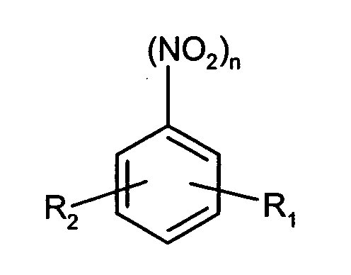
- the aromatic nitro compound in particular those of the following formula can be hydrogenated: wherein R 1 and R 2 are the same or different and are hydrogen or C 1 - to C 4 alkyl, in particular methyl and ethyl, and n is 1 or 2.
- Nitrobenzene or the isomeric nitrotoluenes are preferably hydrogenated by the process according to the invention.
- the catalyst may be e.g. in an adiabatic Reactor as described for the preparation of aromatic amines according to EP-B 0 696 574 is to be used.
- the use of monolithic carrier according to the invention Method is also possible in thermostatically controlled reactors. However, the use is such monolithic supports in thermostated reactors due to the poor radial Heat dissipation, especially on an industrial scale, usually less advantageous.
- EP-B 0 696 574 is for the adiabatic reaction in the hydrogenation of nitroaromatics a hydrogen / nitro group ratio of 60: 1 to 800: 1 sought.
- a hydrogen / nitro group ratio of 60: 1 to 800: 1 sought.
- the reaction becomes driven with a very large excess of hydrogen. Due to the high excess of hydrogen the gas volume flows in commercial production plants become very large. thats why a low pressure drop in the reactor is an important criterion in the selection of the catalyst.
- Monolithic supports, e.g. Honeycomb body, here have a significant advantage over a comparable catalyst bed on.
- the production of aromatic amines can also be carried out in the process according to the invention a two- or multi-step procedure.
- the reaction is e.g. initially in an isothermally operated, thermostatically controlled Main reactor carried out with a fixed catalyst bed, the degree of conversion 80% to 100%.
- a fixed catalyst bed the degree of conversion 80% to 100%.
- At reactors with fixed catalyst bed this leads to a breakthrough of the bed. From At this time, the nitroaromatics may due to the deactivation of the catalyst bed no longer be 100% implemented.
- the downstream, adiabatically operated post-reactor is then used to complete the conversion to 100%, if the degree of conversion of the main reactor is less than 100%.
- the adiabatic postreactor By using the adiabatic postreactor, the Increase service life of the main isothermal reactor.
- the present invention in connection with the retrofitting of existing thermostated tube bundle reactors with the aim of increasing the space-time yield.
- the method is two-stage, wherein in the first Stage is an isothermally operated, thermostatically controlled main reactor with a fixed catalyst bed and in the second stage an adiabatically operated post-reactor with a catalyst, comprising a monolithic carrier is used.
- the catalyst bed is in the Main reactor diluted with inert material.
- the dilution of the catalyst bed with inert material allows an increase of the catalyst loading, e.g. in WO 98/46557.
- Diluting material inert material
- the catalyst becomes diluted with 10 to 50 vol .-% inert material, preferably with 20 to 40 vol .-%, inert material.
- the service life of the reactor decreases as less active Catalyst is in the reaction volume. This lifetime loss can be through the use an adiabatically operated secondary reactor can be compensated again.
- By the combination of diluted catalyst bed in a main reactor and adiabatic after-reactor can increase the productivity of the reactor can be increased. This process is particularly suitable for existing ones Reactors.
- the monolithic carrier e.g.
- Honeycomb bodies can be used in the post-reactor, e.g. also Flow rates of more than 10 m / s can be realized. This gives the possibility lower the residence times in the postreactor to values less than 1 s. Therefore, the Selectivity of the main reactor hardly influenced by subsequent reactions in the secondary reactor. Consequently can increase the capacity of existing reactors for the hydrogenation of nitroaromatics by retrofitting an adiabatic post-reactor with monolithic catalyst with very little effort be increased.
- Example 1 Preparation of catalytically coated monolithic honeycomb body
- cylindrical honeycomb bodies of cordierite having a length of 152 mm, a diameter of 30.5 mm and a cell density of 400 cpsi were used.
- the monolithic supports were cleaned, dried and weighed prior to coating.
- a solution of 3.2 g of 25 wt .-% aqueous ammonium polymethacrylate solution ("Darvan C", R.T. Vanderbilt) and 116.8 g of demineralized Water set, then mixed into the then 80.0 g of finely ground catalyst were.
- the solids content of the suspension was thus about 40 wt .-%.
- a honeycomb body was immersed for a few minutes. After removal from the Suspension was allowed to drain the honeycomb body and then blew the with a compressed air gun Channels free. This was followed by drying (2 h at 120 ° C in a circulating air drying cabinet) and a calcination (2 h at 500 ° C in a muffle furnace). Thereafter, the coated honeycomb body weighed again.
- An oil thermostatically controlled tubular reactor with an inner diameter of 26 mm and a Length of 3000 mm was with a catalyst, as described in DE-A 28 49 002, filled.
- a catalyst as described in DE-A 28 49 002, filled.
- the catalyst was first purged with nitrogen, then with hydrogen and then over a period of 49 h at 1000 l / h Hydrogen activated at 240 ° C.
- nitrobenzene was evaporated in a mixture of nitrogen and hydrogen.
- the Nitrobenzene load was slowly increased from 134 g / h to the maximum value of 690 g / h, that the maximum temperature in the bed did not rise above 460 ° C.
- that became Flowed through the reaction tube with a volume flow of the mixture of 8201 / h, wherein a Hydrogen to nitrobenzene molar ratio of 4 to 1 was maintained.
- the nitrogen was completely replaced by hydrogen and the The reaction tube was then charged with 820 l / h of hydrogen.
- the oil temperature was during kept constant at 240 ° C throughout the reaction time.
- the hot spot migrated at a rate of about 1 mm / h through the bed.
- the maximum temperature was at 435 ° C.
- the selectivity was 98.7% after 47 h, 99.5% after 119 h and 99.5% after 408 h.
- Example 1 Into an oil thermostatically controlled tubular reactor having an inside diameter of 32.8 mm used according to Example 1 monolithic honeycomb body used as catalysts.
- the Reaction tube were 5 honeycomb body with a length of 150 mm and a diameter of 30.5 mm introduced.
- the deposited on these 5 honeycomb bodies active catalyst mass, So carrier and catalytically active component, total was 37.5 g.
- the gap between the pipe wall and the honeycomb body was with a heat-resistant fleece (Fa. Carborundum, type FT 1) sealed.
- a protective tube with a movable thermocouple for detecting the temperature in the monolithic Honeycombs.
- the catalyst was first purged with nitrogen, then with hydrogen and finally activated over a period of 3 h with 500 1 / h of hydrogen at 300 ° C.
- Nitrobenzene was evaporated in a mixture of nitrogen and hydrogen.
- the Nitrobenzene loading was gradually increased from 30 g / h to 110 g / h within 72 h.
- Example 1 Into an oil thermostatically controlled tubular reactor having an inside diameter of 32.8 mm used according to Example 1 monolithic honeycomb body used as catalysts.
- the Reaction tube were 5 honeycomb body with a length of 150 mm and a diameter of 30.5 mm introduced.
- the deposited on these 5 honeycomb bodies active catalyst mass, So carrier and catalytically active component, total was 37.5 g.
- the gap between the pipe wall and the honeycomb body was made with a heat-resistant fleece (Carborundum, type FT 1) sealed.
- a protective tube with a movable thermocouple for detecting the temperature in the monolithic Honeycombs.
- the catalyst was first purged with nitrogen, then with hydrogen and finally activated over a period of 24 h with 700 1 / h of hydrogen at 300 ° C.
- aniline and water were evaporated in a molar ratio of 1 to 2 in a hydrogen stream.
- Nitrobenzene was added to the water, the proportion of nitrobenzene was varied based on the aniline used.
- the amount of aniline, water, nitrobenzene and hydrogen passed were varied over a wide operating window (see Table 1).
- the oil temperature was kept constant at 300 ° C during the entire reaction time. In all cases, the nitrobenzene used could be almost completely reacted with the monolithic honeycomb bodies used.
- Example 5 Diluted bed (working example)
- Example 5a Example 5b
- Example 5c nitrobenzene 690 g / h 732 g / h 1236 g / h 2028 g / h hydrogen 820 l / h 852 l / h 1460 l / h 2211 l / h migration rate 1 mm / h 1.7 mm / h 2.3 mm / h 4.4 mm / h T hot spot, max 435 ° C 332 ° C 370 ° C 401 ° C
Landscapes
- Chemical & Material Sciences (AREA)
- Organic Chemistry (AREA)
- Chemical Kinetics & Catalysis (AREA)
- Organic Low-Molecular-Weight Compounds And Preparation Thereof (AREA)
- Low-Molecular Organic Synthesis Reactions Using Catalysts (AREA)
Abstract
Description
| Parameter der durchgeführten Versuche in der Schüttung | ||||
| Fall 1 | Fall 2 | Fall 3 | Fall 4 | |
| Anilin | 612 g/h | 612 g/h | 612 g/h | 1448 g/h |
| Nitrobenzol | 0.1 g/h | 0.6 g/h | 66.6 g/h | 257 g/h |
| Wasserstoff | 450 l/h | 450 l/h | 1685 l/h | 1685 l/h |
| Nitrobenzol im Edukt | 19 ppm | 998 ppm | 9.8 Gew.-% | 15 Gew.-% |
| Nitrobenzol im Produkt | 5 ppm | 3 ppm | 1 ppm | 3 ppm |
| Parameter der durchgeführten Versuche in der Schüttung | ||||
| Beispiel 2 | Beispiel 5a | Beispiel 5b | Beispiel 5c | |
| Nitrobenzol | 690 g/h | 732 g/h | 1236 g/h | 2028 g/h |
| Wasserstoff | 820 l/h | 852 l/h | 1460 l/h | 2211 l/h |
| Wanderungsgeschwindigkeit | 1 mm/h | 1,7 mm/h | 2,3 mm/h | 4,4 mm/h |
| Thot spot,max | 435°C | 332°C | 370°C | 401°C |
Claims (9)
- Verfahren zur Herstellung von aromatischen Aminen durch katalytische Hydrierung von aromatischen Nitroverbindungen, dadurch gekennzeichnet, dass die katalytische Hydrierung mindestens einstufig ausgeführt wird und der Katalysator wenigstens aus einem monolithischen Träger und einer katalytisch aktiven Beschichtung besteht.
- Verfahren nach Anspruch 1, dadurch gekennzeichnet, dass die Zelldichte des monolithischen Trägers 100 bis 900 cpsi, vorzugsweise 200 bis 600 cpsi, beträgt.
- Verfahren nach einem der Ansprüche 1 oder 2, dadurch gekennzeichnet, dass die katalytisch aktive Beschichtung eine Schichtdicke von maximal 250 µm, vorzugsweise von maximal 100 µm, besonders bevorzugt von 10 bis 100 µm, aufweist.
- Verfahren nach einem der Ansprüche 1-3, dadurch gekennzeichnet, dass die katalytisch aktive Beschichtung Platin und/oder Palladium enthält.
- Verfahren nach einem der Ansprüche 1-4, dadurch gekennzeichnet, dass die katalytisch aktive Beschichtung geträgertes Platin und/oder Palladium enthält.
- Verfahren nach einem der Ansprüche 1-5, dadurch gekennzeichnet, dass die katalytische Hydrierung in einem adiabatisch betriebenen Reaktor stattfindet.
- Verfahren nach einem der Ansprüche 1-6, dadurch gekennzeichnet, dass die katalytische Hydrierung bei einem Druck von 1 bis 30 bar, bevorzugt 1 bis 20 bar, besonders bevorzugt 1 bis 15 bar, stattfindet.
- Verfahren nach einem der Ansprüche 1-7, dadurch gekennzeichnet, dass die katalytische Hydrierung bei einer Temperatur von 200 bis 500°C stattfindet.
- Verfahren nach einem der Ansprüche 1-8, dadurch gekennzeichnet, dass die katalytische Hydrierung zweistufig ausgeführt wird, wobei in der zweiten Stufe ein adiabatisch betriebener Reaktor mit einem Katalysator eingesetzt wird, welcher wenigstens aus einem monolithischen Träger und einer katalytisch aktiven Beschichtung besteht.
Applications Claiming Priority (2)
| Application Number | Priority Date | Filing Date | Title |
|---|---|---|---|
| DE10347439A DE10347439A1 (de) | 2003-10-13 | 2003-10-13 | Verfahren zur Herstellung von aromatischen Aminen durch heterogen katalysierte Hydrierung |
| DE10347439 | 2003-10-13 |
Publications (2)
| Publication Number | Publication Date |
|---|---|
| EP1524259A1 true EP1524259A1 (de) | 2005-04-20 |
| EP1524259B1 EP1524259B1 (de) | 2016-06-08 |
Family
ID=34353377
Family Applications (1)
| Application Number | Title | Priority Date | Filing Date |
|---|---|---|---|
| EP04023292.8A Expired - Lifetime EP1524259B1 (de) | 2003-10-13 | 2004-09-30 | Verfahren zur Herstellung von aromatischen Aminen durch heterogen katalysierte Hydrierung |
Country Status (9)
| Country | Link |
|---|---|
| US (1) | US7193112B2 (de) |
| EP (1) | EP1524259B1 (de) |
| JP (1) | JP4745638B2 (de) |
| KR (1) | KR101117446B1 (de) |
| CN (1) | CN100415375C (de) |
| BR (1) | BRPI0404434B1 (de) |
| DE (1) | DE10347439A1 (de) |
| SG (1) | SG111261A1 (de) |
| TW (1) | TW200524841A (de) |
Cited By (2)
| Publication number | Priority date | Publication date | Assignee | Title |
|---|---|---|---|---|
| WO2011086050A2 (de) | 2010-01-14 | 2011-07-21 | Bayer Materialscience Ag | Verfahren zur herstellung von aromatischen aminen in der flüssigphase |
| WO2012095356A1 (de) | 2011-01-11 | 2012-07-19 | Bayer Materialscience Ag | Verfahren zur herstellung aromatischer amine |
Families Citing this family (3)
| Publication number | Priority date | Publication date | Assignee | Title |
|---|---|---|---|---|
| DE102006011497A1 (de) * | 2006-03-14 | 2007-09-20 | Bayer Technology Services Gmbh | Verfahren und Vorrichtung zur Herstellung von aromatischen Aminen durch eine heterogen katalysierte Hydrierung |
| CN100455559C (zh) * | 2006-11-08 | 2009-01-28 | 大连理工大学 | 芳香族硝基化合物还原制备芳胺的方法 |
| US8809587B2 (en) * | 2010-12-30 | 2014-08-19 | Kellogg Brown & Root Llc | Systems and methods for producing aromatic amines and removing phenol therefrom |
Citations (3)
| Publication number | Priority date | Publication date | Assignee | Title |
|---|---|---|---|---|
| EP0978505A2 (de) * | 1998-08-07 | 2000-02-09 | Air Products And Chemicals, Inc. | Verfahren zur Hydrierung von Dinitrotoluol zu Toluenediamin mittels eines monolithischen Katalysators |
| EP1254715A2 (de) * | 2001-04-20 | 2002-11-06 | Air Products And Chemicals, Inc. | Beschichtetes monolilhisches Substrat und Katalysatoren enthaltend dieses Substrat als Träger |
| EP1336428A2 (de) * | 2002-02-15 | 2003-08-20 | Air Products And Chemicals, Inc. | Katalysatorhalter und Rührsystem zum Umbauen eines Rührkesselreaktors in einen Festbettreaktor |
Family Cites Families (10)
| Publication number | Priority date | Publication date | Assignee | Title |
|---|---|---|---|---|
| US3136818A (en) | 1960-01-15 | 1964-06-09 | Basf Ag | Production of aniline |
| GB1452466A (en) | 1975-04-04 | 1976-10-13 | Chemopetrol | Process for the production of aniline and apparatus therefor |
| DE2849002A1 (de) | 1978-11-11 | 1980-05-22 | Bayer Ag | Verfahren zur katalytischen hydrierung von nitrobenzol |
| DE4428017A1 (de) * | 1994-08-08 | 1996-02-15 | Bayer Ag | Verfahren zur Herstellung von aromatischen Aminen |
| DE4428018A1 (de) | 1994-08-08 | 1996-02-15 | Bayer Ag | Verfahren zur Herstellung von aromatischen Aminen |
| DE19651688A1 (de) | 1996-12-12 | 1998-06-18 | Bayer Ag | Verfahren zur Herstellung von aromatischen Aminen durch Gasphasenhydrierung |
| DE19931902A1 (de) | 1999-07-08 | 2001-01-18 | Consortium Elektrochem Ind | Verfahren zur Herstellung von monolithischen Oxidationskatalysatoren und deren Verwendung bei der Gasphasenoxidation von Kohlenwasserstoffen |
| DE19963443A1 (de) * | 1999-12-28 | 2001-07-05 | Basf Ag | Dünnschichtkatalysatoren auf Basis von Raney-Legierungen und Verfahren zu deren Herstellung |
| US6479704B1 (en) | 2001-04-20 | 2002-11-12 | Air Products And Chemicals, Inc. | Hydrogenation with monolith reactor under conditions of immiscible liquid phases |
| US7109378B2 (en) * | 2001-08-30 | 2006-09-19 | Air Products And Chemicals, Inc. | Monolith catalytic reactor coupled to static mixer |
-
2003
- 2003-10-13 DE DE10347439A patent/DE10347439A1/de not_active Withdrawn
-
2004
- 2004-09-30 EP EP04023292.8A patent/EP1524259B1/de not_active Expired - Lifetime
- 2004-10-07 US US10/960,455 patent/US7193112B2/en not_active Expired - Fee Related
- 2004-10-12 KR KR1020040081209A patent/KR101117446B1/ko not_active Expired - Fee Related
- 2004-10-12 TW TW093130796A patent/TW200524841A/zh unknown
- 2004-10-12 SG SG200406199A patent/SG111261A1/en unknown
- 2004-10-13 BR BRPI0404434-7A patent/BRPI0404434B1/pt not_active IP Right Cessation
- 2004-10-13 JP JP2004298640A patent/JP4745638B2/ja not_active Expired - Fee Related
- 2004-10-13 CN CNB2004100835835A patent/CN100415375C/zh not_active Expired - Fee Related
Patent Citations (3)
| Publication number | Priority date | Publication date | Assignee | Title |
|---|---|---|---|---|
| EP0978505A2 (de) * | 1998-08-07 | 2000-02-09 | Air Products And Chemicals, Inc. | Verfahren zur Hydrierung von Dinitrotoluol zu Toluenediamin mittels eines monolithischen Katalysators |
| EP1254715A2 (de) * | 2001-04-20 | 2002-11-06 | Air Products And Chemicals, Inc. | Beschichtetes monolilhisches Substrat und Katalysatoren enthaltend dieses Substrat als Träger |
| EP1336428A2 (de) * | 2002-02-15 | 2003-08-20 | Air Products And Chemicals, Inc. | Katalysatorhalter und Rührsystem zum Umbauen eines Rührkesselreaktors in einen Festbettreaktor |
Cited By (3)
| Publication number | Priority date | Publication date | Assignee | Title |
|---|---|---|---|---|
| WO2011086050A2 (de) | 2010-01-14 | 2011-07-21 | Bayer Materialscience Ag | Verfahren zur herstellung von aromatischen aminen in der flüssigphase |
| WO2012095356A1 (de) | 2011-01-11 | 2012-07-19 | Bayer Materialscience Ag | Verfahren zur herstellung aromatischer amine |
| US9139510B2 (en) | 2011-01-11 | 2015-09-22 | Bayer Intellectual Property Gmbh | Process for preparing aromatic amines |
Also Published As
| Publication number | Publication date |
|---|---|
| DE10347439A1 (de) | 2005-05-04 |
| BRPI0404434A (pt) | 2005-06-21 |
| SG111261A1 (en) | 2005-05-30 |
| TW200524841A (en) | 2005-08-01 |
| BRPI0404434B1 (pt) | 2014-03-25 |
| EP1524259B1 (de) | 2016-06-08 |
| KR101117446B1 (ko) | 2012-03-20 |
| CN1621153A (zh) | 2005-06-01 |
| KR20050035502A (ko) | 2005-04-18 |
| CN100415375C (zh) | 2008-09-03 |
| JP2005120087A (ja) | 2005-05-12 |
| JP4745638B2 (ja) | 2011-08-10 |
| US7193112B2 (en) | 2007-03-20 |
| US20050080293A1 (en) | 2005-04-14 |
Similar Documents
| Publication | Publication Date | Title |
|---|---|---|
| EP1882681B1 (de) | Verfahren zur Herstellung von aromatischen Aminen | |
| EP1033361B1 (de) | Verfahren zur Herstellung von Aminen | |
| EP1137623B1 (de) | Verfahren zur herstellung von aminen | |
| KR100339285B1 (ko) | 디니트로톨루엔을 톨루엔디아민으로 가수소화시키는데 유용한모놀리스 촉매 | |
| EP1066111B1 (de) | Raney-nickel-katalysatoren, ein verfahren zu deren herstellung und deren verwendung zur hydrierung organischer verbindungen | |
| EP0944578B1 (de) | Verfahren zur herstellung von aromatischen aminen durch gasphasenhydrierung | |
| EP3080071A2 (de) | Verfahren zur hydrierung aromatischer verbindungen | |
| EP0881206B1 (de) | Verfahren zur kontinuierlichen technischen Herstellung ungesättigter aliphatischer Aldehyde in einem Rohrbündelreaktor | |
| EP2429983A2 (de) | Verfahren zur herstellung von aromatischen aminen | |
| EP1804963B1 (de) | Reaktor und verfahren zur synthese von vinylacetat in der gasphase | |
| EP0748790B1 (de) | Verfahren und Katalysator zur Herstellung von aromatischen Aminen durch Gasphasenhydrierung | |
| EP1524259B1 (de) | Verfahren zur Herstellung von aromatischen Aminen durch heterogen katalysierte Hydrierung | |
| DE2135154B2 (de) | Verfahren zur Herstellung von Aminoverbindungen durch kontinuierliche Reduktion von Nitroverbindungen | |
| EP0748789B1 (de) | Verfahren und Katalysator zur Herstellung von aromatischen Aminen durch Gasphasenhydrierung | |
| EP0975578B1 (de) | Herstellung von aromatischen aminen mittels neuer hydrierkatalysatoren | |
| DE19857409A1 (de) | Verfahren zur Herstellung von Aminen | |
| EP2125192A1 (de) | Verfahren und vorrichtung zur herstellung von aromatischen aminen durch eine heterogen katalysierte hydrierung | |
| EP2663544B1 (de) | Verfahren zur herstellung aromatischer amine | |
| EP1342713B1 (de) | Verfahren zur Herstellung eines Dinitronaphthalin-Isomerengemisches mit hohem Anteil an 1,5-Dinitronaphtalin | |
| DE4433023A1 (de) | Katalysator für die Hydrierung von Nitroaromaten und Verfahren zu seiner Herstellung | |
| HK1078816A (en) | Process for the production of aromatic amines by heterogeneously catalysed hydrogenation |
Legal Events
| Date | Code | Title | Description |
|---|---|---|---|
| PUAI | Public reference made under article 153(3) epc to a published international application that has entered the european phase |
Free format text: ORIGINAL CODE: 0009012 |
|
| AK | Designated contracting states |
Kind code of ref document: A1 Designated state(s): AT BE BG CH CY CZ DE DK EE ES FI FR GB GR HU IE IT LI LU MC NL PL PT RO SE SI SK TR |
|
| AX | Request for extension of the european patent |
Extension state: AL HR LT LV MK |
|
| 17P | Request for examination filed |
Effective date: 20051020 |
|
| AKX | Designation fees paid |
Designated state(s): AT BE BG CH CY CZ DE DK EE ES FI FR GB GR HU IE IT LI LU MC NL PL PT RO SE SI SK TR |
|
| 17Q | First examination report despatched |
Effective date: 20070716 |
|
| RAP1 | Party data changed (applicant data changed or rights of an application transferred) |
Owner name: BAYER INTELLECTUAL PROPERTY GMBH |
|
| RAP1 | Party data changed (applicant data changed or rights of an application transferred) |
Owner name: COVESTRO DEUTSCHLAND AG |
|
| GRAP | Despatch of communication of intention to grant a patent |
Free format text: ORIGINAL CODE: EPIDOSNIGR1 |
|
| INTG | Intention to grant announced |
Effective date: 20151106 |
|
| INTG | Intention to grant announced |
Effective date: 20160104 |
|
| GRAS | Grant fee paid |
Free format text: ORIGINAL CODE: EPIDOSNIGR3 |
|
| GRAA | (expected) grant |
Free format text: ORIGINAL CODE: 0009210 |
|
| AK | Designated contracting states |
Kind code of ref document: B1 Designated state(s): AT BE BG CH CY CZ DE DK EE ES FI FR GB GR HU IE IT LI LU MC NL PL PT RO SE SI SK TR |
|
| REG | Reference to a national code |
Ref country code: GB Ref legal event code: FG4D Free format text: NOT ENGLISH |
|
| REG | Reference to a national code |
Ref country code: CH Ref legal event code: EP |
|
| REG | Reference to a national code |
Ref country code: IE Ref legal event code: FG4D Free format text: LANGUAGE OF EP DOCUMENT: GERMAN |
|
| REG | Reference to a national code |
Ref country code: AT Ref legal event code: REF Ref document number: 805116 Country of ref document: AT Kind code of ref document: T Effective date: 20160715 |
|
| REG | Reference to a national code |
Ref country code: DE Ref legal event code: R096 Ref document number: 502004015216 Country of ref document: DE |
|
| REG | Reference to a national code |
Ref country code: NL Ref legal event code: MP Effective date: 20160608 |
|
| PG25 | Lapsed in a contracting state [announced via postgrant information from national office to epo] |
Ref country code: FI Free format text: LAPSE BECAUSE OF FAILURE TO SUBMIT A TRANSLATION OF THE DESCRIPTION OR TO PAY THE FEE WITHIN THE PRESCRIBED TIME-LIMIT Effective date: 20160608 |
|
| PG25 | Lapsed in a contracting state [announced via postgrant information from national office to epo] |
Ref country code: GR Free format text: LAPSE BECAUSE OF FAILURE TO SUBMIT A TRANSLATION OF THE DESCRIPTION OR TO PAY THE FEE WITHIN THE PRESCRIBED TIME-LIMIT Effective date: 20160909 Ref country code: NL Free format text: LAPSE BECAUSE OF FAILURE TO SUBMIT A TRANSLATION OF THE DESCRIPTION OR TO PAY THE FEE WITHIN THE PRESCRIBED TIME-LIMIT Effective date: 20160608 Ref country code: SE Free format text: LAPSE BECAUSE OF FAILURE TO SUBMIT A TRANSLATION OF THE DESCRIPTION OR TO PAY THE FEE WITHIN THE PRESCRIBED TIME-LIMIT Effective date: 20160608 Ref country code: ES Free format text: LAPSE BECAUSE OF FAILURE TO SUBMIT A TRANSLATION OF THE DESCRIPTION OR TO PAY THE FEE WITHIN THE PRESCRIBED TIME-LIMIT Effective date: 20160608 |
|
| PG25 | Lapsed in a contracting state [announced via postgrant information from national office to epo] |
Ref country code: SK Free format text: LAPSE BECAUSE OF FAILURE TO SUBMIT A TRANSLATION OF THE DESCRIPTION OR TO PAY THE FEE WITHIN THE PRESCRIBED TIME-LIMIT Effective date: 20160608 Ref country code: RO Free format text: LAPSE BECAUSE OF FAILURE TO SUBMIT A TRANSLATION OF THE DESCRIPTION OR TO PAY THE FEE WITHIN THE PRESCRIBED TIME-LIMIT Effective date: 20160608 Ref country code: CZ Free format text: LAPSE BECAUSE OF FAILURE TO SUBMIT A TRANSLATION OF THE DESCRIPTION OR TO PAY THE FEE WITHIN THE PRESCRIBED TIME-LIMIT Effective date: 20160608 Ref country code: EE Free format text: LAPSE BECAUSE OF FAILURE TO SUBMIT A TRANSLATION OF THE DESCRIPTION OR TO PAY THE FEE WITHIN THE PRESCRIBED TIME-LIMIT Effective date: 20160608 Ref country code: IT Free format text: LAPSE BECAUSE OF FAILURE TO SUBMIT A TRANSLATION OF THE DESCRIPTION OR TO PAY THE FEE WITHIN THE PRESCRIBED TIME-LIMIT Effective date: 20160608 |
|
| PG25 | Lapsed in a contracting state [announced via postgrant information from national office to epo] |
Ref country code: PL Free format text: LAPSE BECAUSE OF FAILURE TO SUBMIT A TRANSLATION OF THE DESCRIPTION OR TO PAY THE FEE WITHIN THE PRESCRIBED TIME-LIMIT Effective date: 20160608 Ref country code: PT Free format text: LAPSE BECAUSE OF FAILURE TO SUBMIT A TRANSLATION OF THE DESCRIPTION OR TO PAY THE FEE WITHIN THE PRESCRIBED TIME-LIMIT Effective date: 20161010 Ref country code: BE Free format text: LAPSE BECAUSE OF NON-PAYMENT OF DUE FEES Effective date: 20160930 |
|
| REG | Reference to a national code |
Ref country code: DE Ref legal event code: R097 Ref document number: 502004015216 Country of ref document: DE |
|
| REG | Reference to a national code |
Ref country code: DE Ref legal event code: R119 Ref document number: 502004015216 Country of ref document: DE |
|
| PLBE | No opposition filed within time limit |
Free format text: ORIGINAL CODE: 0009261 |
|
| STAA | Information on the status of an ep patent application or granted ep patent |
Free format text: STATUS: NO OPPOSITION FILED WITHIN TIME LIMIT |
|
| PG25 | Lapsed in a contracting state [announced via postgrant information from national office to epo] |
Ref country code: MC Free format text: LAPSE BECAUSE OF FAILURE TO SUBMIT A TRANSLATION OF THE DESCRIPTION OR TO PAY THE FEE WITHIN THE PRESCRIBED TIME-LIMIT Effective date: 20160608 |
|
| REG | Reference to a national code |
Ref country code: CH Ref legal event code: PL |
|
| 26N | No opposition filed |
Effective date: 20170309 |
|
| GBPC | Gb: european patent ceased through non-payment of renewal fee |
Effective date: 20160930 |
|
| PG25 | Lapsed in a contracting state [announced via postgrant information from national office to epo] |
Ref country code: DK Free format text: LAPSE BECAUSE OF FAILURE TO SUBMIT A TRANSLATION OF THE DESCRIPTION OR TO PAY THE FEE WITHIN THE PRESCRIBED TIME-LIMIT Effective date: 20160608 Ref country code: SI Free format text: LAPSE BECAUSE OF FAILURE TO SUBMIT A TRANSLATION OF THE DESCRIPTION OR TO PAY THE FEE WITHIN THE PRESCRIBED TIME-LIMIT Effective date: 20160608 |
|
| REG | Reference to a national code |
Ref country code: IE Ref legal event code: MM4A |
|
| REG | Reference to a national code |
Ref country code: FR Ref legal event code: ST Effective date: 20170531 |
|
| PG25 | Lapsed in a contracting state [announced via postgrant information from national office to epo] |
Ref country code: DE Free format text: LAPSE BECAUSE OF NON-PAYMENT OF DUE FEES Effective date: 20170401 Ref country code: GB Free format text: LAPSE BECAUSE OF NON-PAYMENT OF DUE FEES Effective date: 20160930 Ref country code: CH Free format text: LAPSE BECAUSE OF NON-PAYMENT OF DUE FEES Effective date: 20160930 Ref country code: LI Free format text: LAPSE BECAUSE OF NON-PAYMENT OF DUE FEES Effective date: 20160930 Ref country code: FR Free format text: LAPSE BECAUSE OF NON-PAYMENT OF DUE FEES Effective date: 20160930 Ref country code: IE Free format text: LAPSE BECAUSE OF NON-PAYMENT OF DUE FEES Effective date: 20160930 |
|
| PG25 | Lapsed in a contracting state [announced via postgrant information from national office to epo] |
Ref country code: LU Free format text: LAPSE BECAUSE OF NON-PAYMENT OF DUE FEES Effective date: 20160930 |
|
| REG | Reference to a national code |
Ref country code: AT Ref legal event code: MM01 Ref document number: 805116 Country of ref document: AT Kind code of ref document: T Effective date: 20160930 |
|
| REG | Reference to a national code |
Ref country code: BE Ref legal event code: MM Effective date: 20160930 |
|
| PG25 | Lapsed in a contracting state [announced via postgrant information from national office to epo] |
Ref country code: AT Free format text: LAPSE BECAUSE OF NON-PAYMENT OF DUE FEES Effective date: 20160930 |
|
| PG25 | Lapsed in a contracting state [announced via postgrant information from national office to epo] |
Ref country code: CY Free format text: LAPSE BECAUSE OF FAILURE TO SUBMIT A TRANSLATION OF THE DESCRIPTION OR TO PAY THE FEE WITHIN THE PRESCRIBED TIME-LIMIT Effective date: 20160608 Ref country code: HU Free format text: LAPSE BECAUSE OF FAILURE TO SUBMIT A TRANSLATION OF THE DESCRIPTION OR TO PAY THE FEE WITHIN THE PRESCRIBED TIME-LIMIT; INVALID AB INITIO Effective date: 20040930 |
|
| PG25 | Lapsed in a contracting state [announced via postgrant information from national office to epo] |
Ref country code: TR Free format text: LAPSE BECAUSE OF FAILURE TO SUBMIT A TRANSLATION OF THE DESCRIPTION OR TO PAY THE FEE WITHIN THE PRESCRIBED TIME-LIMIT Effective date: 20160608 |
|
| PG25 | Lapsed in a contracting state [announced via postgrant information from national office to epo] |
Ref country code: BG Free format text: LAPSE BECAUSE OF FAILURE TO SUBMIT A TRANSLATION OF THE DESCRIPTION OR TO PAY THE FEE WITHIN THE PRESCRIBED TIME-LIMIT Effective date: 20160608 |