EP1523907B1 - Shelf system - Google Patents
Shelf system Download PDFInfo
- Publication number
- EP1523907B1 EP1523907B1 EP20040024112 EP04024112A EP1523907B1 EP 1523907 B1 EP1523907 B1 EP 1523907B1 EP 20040024112 EP20040024112 EP 20040024112 EP 04024112 A EP04024112 A EP 04024112A EP 1523907 B1 EP1523907 B1 EP 1523907B1
- Authority
- EP
- European Patent Office
- Prior art keywords
- shelving
- upright
- shelf
- shelving system
- insert part
- Prior art date
- Legal status (The legal status is an assumption and is not a legal conclusion. Google has not performed a legal analysis and makes no representation as to the accuracy of the status listed.)
- Active
Links
- 230000013011 mating Effects 0.000 claims description 12
- 230000000295 complement effect Effects 0.000 claims description 11
- XAGFODPZIPBFFR-UHFFFAOYSA-N aluminium Chemical compound [Al] XAGFODPZIPBFFR-UHFFFAOYSA-N 0.000 description 8
- 229910052782 aluminium Inorganic materials 0.000 description 8
- 238000010276 construction Methods 0.000 description 4
- HCHKCACWOHOZIP-UHFFFAOYSA-N Zinc Chemical compound [Zn] HCHKCACWOHOZIP-UHFFFAOYSA-N 0.000 description 3
- 239000011701 zinc Substances 0.000 description 3
- 229910052725 zinc Inorganic materials 0.000 description 3
- 238000011161 development Methods 0.000 description 2
- 230000018109 developmental process Effects 0.000 description 2
- 238000006073 displacement reaction Methods 0.000 description 2
- 238000009434 installation Methods 0.000 description 2
- 229910000831 Steel Inorganic materials 0.000 description 1
- 238000009749 continuous casting Methods 0.000 description 1
- 230000001419 dependent effect Effects 0.000 description 1
- 238000007654 immersion Methods 0.000 description 1
- 238000004519 manufacturing process Methods 0.000 description 1
- 239000000463 material Substances 0.000 description 1
- 230000002093 peripheral effect Effects 0.000 description 1
- 239000011295 pitch Substances 0.000 description 1
- 239000000843 powder Substances 0.000 description 1
- 239000010959 steel Substances 0.000 description 1
- 230000007704 transition Effects 0.000 description 1
Images


Classifications
-
- A—HUMAN NECESSITIES
- A47—FURNITURE; DOMESTIC ARTICLES OR APPLIANCES; COFFEE MILLS; SPICE MILLS; SUCTION CLEANERS IN GENERAL
- A47B—TABLES; DESKS; OFFICE FURNITURE; CABINETS; DRAWERS; GENERAL DETAILS OF FURNITURE
- A47B47/00—Cabinets, racks or shelf units, characterised by features related to dismountability or building-up from elements
- A47B47/02—Cabinets, racks or shelf units, characterised by features related to dismountability or building-up from elements made of metal only
- A47B47/021—Racks or shelf units
- A47B47/022—Racks or shelf units with cantilever shelves
-
- A—HUMAN NECESSITIES
- A47—FURNITURE; DOMESTIC ARTICLES OR APPLIANCES; COFFEE MILLS; SPICE MILLS; SUCTION CLEANERS IN GENERAL
- A47B—TABLES; DESKS; OFFICE FURNITURE; CABINETS; DRAWERS; GENERAL DETAILS OF FURNITURE
- A47B57/00—Cabinets, racks or shelf units, characterised by features for adjusting shelves or partitions
- A47B57/06—Cabinets, racks or shelf units, characterised by features for adjusting shelves or partitions with means for adjusting the height of the shelves
- A47B57/18—Cabinets, racks or shelf units, characterised by features for adjusting shelves or partitions with means for adjusting the height of the shelves consisting of screwbolts as connecting members
-
- A—HUMAN NECESSITIES
- A47—FURNITURE; DOMESTIC ARTICLES OR APPLIANCES; COFFEE MILLS; SPICE MILLS; SUCTION CLEANERS IN GENERAL
- A47B—TABLES; DESKS; OFFICE FURNITURE; CABINETS; DRAWERS; GENERAL DETAILS OF FURNITURE
- A47B96/00—Details of cabinets, racks or shelf units not covered by a single one of groups A47B43/00 - A47B95/00; General details of furniture
- A47B96/14—Bars, uprights, struts, or like supports, for cabinets, brackets, or the like
- A47B96/1408—Bars, uprights, struts, or like supports, for cabinets, brackets, or the like regularly perforated
Definitions
- the present invention relates to a shelving system, in particular for mobile use in a vehicle, according to the preamble of claim 1.
- a shelf includes vertical shelf posts to which, among other things, shelves are attached.
- the shelves are z. B. hooked at your corners to the respective shelf posts, screwed or otherwise determined.
- For torsional rigidity of such a shelf a shelf rear wall or diagonal struts are provided, otherwise the shelf must be bolted to a wall.
- a disadvantage is that such shelves can not be easily extended or shortened spatially. Warehousing is complex and difficult to install in a vehicle.
- FR 2 145 882 A a shelving system in which the vertical shelf posts are held torsionally rigid with latchable struts therein by the strut has a contour which is complementary to the outer shape of the post and this engages over two outer surfaces of the post.
- a lateral extension of the shelving system is not possible due to the enclosure of the post, if several shelf inserts are to be mounted side by side at the same height.
- Analog shows the DE 1 183 215 B a shelf in which the respective front and rear shelf posts are braced with mounting rails, which support rails engage around the relevant post on two outer surfaces.
- the basic idea of the invention is to provide a shelving system in which shelf posts to be arranged vertically are supported by insert elements to be arranged horizontally to the shelf posts, such that a torsionally rigid bracing of the shelf posts is provided by a positive and non-positive reception of the insert part on abutment surfaces of the respective shelf post.
- the insert has complementary mating surfaces, which lie flush against the approach surfaces in the mounted state of the insert. According to the invention u.a. provided that in the approach surface a groove is provided and the insert part has on its counter surface a nose which engages in the mounted state in the groove.
- a nose is provided which engages in a groove of the counter surface of the insert part.
- the approach surface of the shelf post extends in an advantageous manner over the entire height of the shelf post, so that the positive and non-positive reception of an insert part at any height on the shelf post is possible.
- the mating surfaces on the insert have a height of 3 - 5 cm, preferably 4 cm, to ensure a stable contact with the respective approach surface of the shelf post.
- the shelf post is formed from a hollow profile, are provided on the parallel webs for screwing with the insert parts. Mounting holes in the webs in grid height intervals serve to accommodate mounting screws.
- the shelf post hollow section is open at its on the installation state related outside.
- the hollow profile can be further attachments, such as panels, rubberized protection profiles, strips, Blinds guides, etc. fasten.
- the opening does not extend completely across the width of the shelf post but is in the form of a slot opening, such that the head of a screw from above or below can be inserted into the hollow profile and the screw thread protrudes through the slot opening to the outside.
- the screw is then fixed with its head in the hollow profile, which can be attached to the screw thread above attachments by screwing a nut. After tightening the nut, the attachments are firmly attached to the hollow profile.
- a specially designed for the front of the shelf front shelf post can be provided for the shelf, which has an integral widened end part in the form of a roof-shaped tip.
- respective shelf posts on both sides of its central axis is mirror-symmetrical with respective approach surfaces for positive and non-positive reception of an insert part formed on both sides of the shelf post, so that the shelving system is expandable to each side direction.
- the insert part is formed from a frame profile and a separate corner angle, on which the mating surfaces are formed and on whose legs in each case the frame profile can be fixed.
- the frame profile can be riveted or clinched at the corner angle. Due to the separate execution of corner and frame profile inserts can be composed of these elements, with the frame size of the insert in width and length can be determined arbitrarily by the length of the frame profiles.
- the frame profile is advantageously made of extruded aluminum
- the corner angle can also be made of zinc die-cast or die-cast aluminum.
- the shelf post has two mutually perpendicularly arranged abutment surfaces, and the insert part or the corner angle two counter-surfaces complementary thereto.
- the corner angle is positively and non-positively fixed by the two mutually perpendicular approach surfaces of the shelf post at this.
- Advantageously according to this embodiment is in both approach surfaces of the Shelf each provided a groove into which a nose of the insert part or the corner angle can intervene. While in this embodiment two abutment surfaces are provided with a respective groove, it is considered sufficient to provide only a single mating surface of the insert part or the corner angle with a nose.
- the respective groove also extends advantageously over the entire height of the shelf post, so that the insert part or the corner angle can be fixed at any height with his nose on the shelf post. Furthermore, advantageously, the nose of the mating surface extends over the entire height of the insert part or the corner angle.
- This construction of an engagement between the groove and the nose can, of course, also be provided in reverse, that is to say that a lug is provided on the abutment surface of the shelf post and the grooves are formed on the insert part or the corner angle.
- inserts may also include trays, or shelves.
- the shelving system may further include add-on elements such as drawers, trolleys, cabinet inserts, as well as cabinet doors or lift doors. Due to the stable warp-resistant structure of the shelving system, it is not necessary to incorporate these add-on elements, such as a drawer or a drawer pull itself in a torsion-resistant frame, which frame would then be inserted into the shelf.
- the support system composed of the shelf post and the insert part provides sufficient stability as a frame structure for an attachment element that can be fastened to the shelf post and / or the insert part (s).
- a post holder for additional attachment or for pulling in an intermediate post, which is positively and non-positively fixed to an insert part, or on a frame profile and having a head part to which a intermediate post in the required height can be fastened.
- the intermediate post is advantageously a shortened shelf post.
- the post holder is advantageously made of zinc pressure or die-cast aluminum.
- the shelving system is particularly suitable for installation in a vehicle. Since additional means for stiffening the shelving system are not required, the shelving system has an advantageously low weight.
- an immersion rail is provided according to an advantageous embodiment, with the course of a shelf post is displaceable. This measure is necessary if the shelf is to be installed on a vehicle wall that has a bulge.
- the front shelf posts of the shelf are set in the vehicle interior, while the rear shelf posts must adapt to the wall curvature.
- the depth jump rail can also be used as a fastener for attachment of shelf modules, such as a fold-out workbench according to DE 197 46 859 A1 serve.
- the depth jump rail can be provided with internal threads, can be screwed into the bolts of the respective shelf module.
- the depth jump rail is advantageously made of zinc or die-cast aluminum.
- a lashing according to DE 102 54 505 be fixed to a shelf post or an insert part or frame profile.
- the help of the lashing rail can be larger objects with the help of tensioning straps or the like secure in the vehicle interior by a tensioning strap is hung on the lashing and the strap surrounds an object to be held.
- Fig. 1 shows a perspective view of the basic structure of the shelving system according to the invention.
- two insert parts 12 are arranged at different heights, which serve for the strut of the shelf posts.
- a terminating rail 22 is mounted at the upper ends of each of a front shelf post 10 and a rear shelf post 11, to facilitate better handling and also to give an operator an opportunity to hold onto an operator just as the shelf system is used in a vehicle.
- a shelf trough 24 attached to the shelf posts 10, 11.
- the insert 12 is designed as an integral part of the tub, with which the tub 24 is then set by means of the integrated insert to the shelf posts.
- the reference numeral 25 so-called. Suitcases are marked, which have an extendable on rails frame, on which a suitcase can be mounted non-slip. By pulling on the suitcase handle, the suitcase pull is pulled out of the shelving system. Separated by a intermediate post 21 next to drawers 26 are arranged.
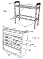
- the shelving system is provided on its side walls respectively with side wall panels 20 which are removable to extend the shelf. According to the in Fig. 2 Shown embodiment, the front shelf posts 10 and the front intermediate post 21 are projecting with a forward roof-shaped point (see detail 41 in Fig. 5 or 8).
- the arranged in the shelf system shown add-on elements 25, 26 are set back with its front end surface by the height of the roof-shaped tip with respect to this when the attachments are in their retracted or folded position.
- Fig. 3 shows a perspective view of another shelf system according to the invention consisting of two front shelf posts 10 and two rear shelf posts 11, which correspond by an insert member 12 in the form of a peripheral frame Fig. 1 or by means of a trough 24 are braced together.
- the shelf posts 10, 11 and the respective insert 12 are light in weight, since the shelf posts 10, 11 and the insert parts 12, or the frame profiles 12 a made of aluminum continuous casting and formed according to the advantageous embodiment shown as hollow sections (see esp. Fig. 5 . 6 . 7 and 8th ), which combines low weight and high torsional rigidity.
- the panel can be made of aluminum or sheet steel, which materials can be powder coated.
- the panel can be pushed or glued onto the insert part 12 or the frame profile 12a (see FIG Fig. 10 ). Furthermore, it is possible to clip the panel on the frame part 12, as in Fig. 7 is shown.
- Fig. 4 shows a corresponding perspective view of the shelving system according to the invention with inserted into the upper shelf area drawers 26. These drawers 26 are independent of each other on the shelf posts 10, 11 and on the Intermediate post 21 attached. Furthermore, in this embodiment, two lashing rails 17 are fastened to respectively one lower and one upper insert part 12 and to the trough 24.
- the front shelf posts 10 are provided with a projecting roof-shaped pointed towards the front. Unlike the in Fig. 2 In the embodiment shown, the front surfaces of the respective attachment elements 26, 34 form a flush closure with the front edge of the roof-shaped tip, so that in the retracted or folded state of the respective attachment element, this covers the tip with the exception of the front edge.
- Fig. 5 shows an embodiment of the shelf system according to the invention for two front shelf posts 10.
- These shelf posts 10 are made as a hollow profile of extruded aluminum.
- the insert 12 shown is composed of corner angles 14 and separate frame profiles 12a thereof. As shown in the figure on the right side, can be defined by the mirror-symmetrical design of the shelf posts 10, 11 on both sides of a shelf post 10, 11 corner bracket 14, whereby the shelving system is expandable to each side.
- Parallel webs 43 are integrally formed on the shelf pillar hollow profile.
- the front shelf post 10 is provided with a roof-shaped tip, which projects beyond the insert part 12 and the frame profile 12 a forward.
- a rear shelf post 11 marked shelf post has a slot opening, which may also be provided in a front shelf post 10, wherein by means of the slot formed by the slot opening receiving groove 47, for example, a blind guide can be attached to the shelf post, so that the shelf to his Front is covered by a blind.
- a blind guide can be attached to the shelf post, so that the shelf to his Front is covered by a blind.
- the head of a bolt can be inserted into the receiving groove from above or from below into the rack post, wherein the thread of the bolt protrudes through the slot opening to the outside of the shelf post and can be screwed from the outside with a locknut.
- Fig. 5 further shows the frame profiles 12a by means of post holders 15 (see detail Fig. 7 and Fig. 10 As shown, the head 15a of a post holder 15 is inserted between the webs 43 of the intermediate post, wherein the Head 15a is fastened by means of a screw through the mounting holes in the webs 43 of the intermediate post 21.
- Fig. 6 shows a further embodiment of the shelving system in a horizontal cross section, consisting of two front shelf posts 10 and two rear shelf posts 11, and an insert member disposed therebetween, which is formed by frame profiles 12a and corner angles 14.
- the corner brackets 14 are riveted or clinched with their legs 52 with the frame profiles 12a.
- a torsionally rigid support of the shelf posts is also given by a positive and non-positive reception of the insert part 12 to each other substantially perpendicularly arranged approach surfaces 13 of the respective shelf post 10, 11.
- the approach surfaces of the shelf post extend here in an advantageous manner over the entire height of the shelf post, so that the positive and non-positive reception of an insert part at any height on the shelf post is possible.
- a corner angle with two complementary mating surfaces 50 is attached.
- each corner angle 14 has a nose 40 which in a complementary groove 36 (in detail in Fig. 8 ) of the respective shelf post 10, 11 engages.
- the provided on the corner bracket 14 nose 40 advantageously extends over the entire height of the corner angle.
- the shelf posts 10, 11 in the Fig. 6 shown at a certain distance from the corner angles 14.
- each corner angle 14 is fixed with its mating surfaces 50 at mutually perpendicular approach surfaces 13 of the respective shelf post.
- Due to the engagement of the nose 40 in the groove 36 of the corner angle is rotationally fixed ie fixed torsion.
- the engagement groove-nose on the front shelf post 10 is offset by 90 ° to the rear shelf posts 11, which further improves the torsional rigidity.
- the assembly of the shelf is easier if the engagement groove-nose on both the rear and the front shelf post as in Fig. 6 at the rear shelf posts shown laterally.
- Fig. 7 Further details of the shelving system are shown.
- the left view shows the section AA Fig. 6
- the corner angle leg is formed from an I-profile, which is inserted into the hollow frame section 12a and riveted or clinched with this.
- the insert 12 is shown with regardklipster aperture 18.
- a post holder 15 is shown as it is fixed to the frame section 12a of the insert part 12. Characterized in that the post holder 15 is formed with a complementary structure to the frame profile, the profiles of these elements fit together, whereby a torsion and torsionally rigid structure between the post holder 15 and the frame section 12a of the insert member 12 is provided for attachment of intermediate posts 21.
- the post holder 15 has a head portion 15 a, on which a shelf intermediate post 21 (see Fig. 3 . 4 or 10 ) is fixable, such that the head part 15 a can be inserted into the formed by the two webs 43 open hollow profile of a shelf post and bolted to it.
- Fig. 8 shows a rear shelf post 11 and a front shelf post 10 in opposite Fig. 6 enlarged view.
- the respective shelf post 10, 11 is mirror-symmetrical with respect to its central axis, so that each shelf post is provided on both sides with a pair of mutually perpendicular approach surfaces 13.
- a groove 36 is formed, whereby it is possible, one with a nose 40 according to Fig. 6 trained corner angle in two rotated positions on the shelf post. So one and the same corner angle can be used for all four corners.
- Both shelf posts 10, 11 are made as a closed double hollow section of extruded aluminum.
- a "depth jump bar” 16 (see Fig. 9 ), the shelf posts 10, 11 in its web portion 60 two inwardly projecting, connected by a transverse web 45 webs 43 with the mounting holes 63 at pitches. To determine the depth jump rail 16, this is introduced between the webs 43 to the cross bar 45 and screwed. For a screwing the depth jump rail is provided at its ends with an internal thread.
- the front shelf post 10 is formed at its forward projecting widened end part 62 as a hollow profile 41 with dachförmigem pointed, which adjoins a central hollow section 42 in the web portion 60. Like that in conjunction with the Figures 3 . 4 can be seen, is provided by the roof-shaped tip of the front hollow section 41 a flush conclusion with complementary beveled drawers 26, panels 18, lashing rails 17, lift doors 30 and cabinet inserts 32 or cabinet doors 34.
- the profile of the rear shelf post 11 is formed so that it can be fixed by means of a fastener, such as a hammer screw and / or a retaining plate to a support, to a wall or the like.
- a fastener such as a hammer screw and / or a retaining plate to a support, to a wall or the like.
- on the rear shelf post 11 on both sides of a receiving groove 47 for the head 48 of the hammer screw hollow holding profiles 44 are formed with a flat end surface 46 as a common end part 62.
- Fig. 9 shows a depth jump rail 16, which between the in Fig. 5 or 8th shown webs 43 of a front shelf post 10 and a rear shelf post 11 inserted and by means of screwing through the mounting holes 63 in the webs 43 of the shelf post can be fixed thereto.
- the integral with the depth jump rail head portion 16a allows a displacement of a shelf post 10, 11 to the inside of the shelf.
- Fig. 10 shows the shelf system according to the invention in a sectional side view.
- a rear shelf post 11 is braced with a front shelf post 10 by two insert parts 12.
- the frame profiles 12a are screwed to the respective shelf posts in mounting holes 63, which are provided in grid height intervals.
- the mounting holes 63 on the rear shelf post 11 are made as elongated holes to provide a suitable mounting clearance for screws to be inserted into the mounting holes.
- a intermediate post 21 is mounted on the front shelf post 10.
- the intermediate post 21 is attached to two post holders 15, which in turn are fixed to a respective frame profile 12a of the insert part.
- the frame profiles 12 a of the insert part are each covered with a diaphragm 18.
- the embodiment shown is the Aperture 18 in Fig. 10 glued to the respective frame profile 12a.
- the frame section 12a has at its front a smaller clearance for receiving the panel so that the patch panel 18 forms with the frame section 12a at its upper and lower surfaces a flush final transition and are pushed so deep to the frame profile may be that the aperture on the front surface of the frame profile 12a is festklebbar.
- a rear intermediate post 21 is attached to the rear shelf post 11 via post holder 15.
- a closure rail 22 is attached, is realized by the impact edge-free upper end of the shelf.
- the end rail 22 is also a suitable handle for an operator, such as getting into the vehicle compartment.
Landscapes
- Assembled Shelves (AREA)
- Vehicle Step Arrangements And Article Storage (AREA)
Description
Die vorliegende Erfindung betrifft ein Regalsystem, insbesondere für den mobilen Einsatz in einem Fahrzeug, gemäß dem Oberbegriff von Anspruch 1.The present invention relates to a shelving system, in particular for mobile use in a vehicle, according to the preamble of claim 1.
Ein Regal umfasst vertikale Regalpfosten, an denen unter anderem Regalböden befestigt sind. Die Regalböden werden z. B. an Ihren Ecken an dem jeweiligen Regalpfosten eingehängt, verschraubt oder anderweitig festgelegt. Zur Verwindungssteifigkeit eines derartigen Regals ist eine Regalrückwand oder es sind Diagonalstreben vorgesehen, andernfalls das Regal an einer Wand verschraubt werden muss. Ein Nachteil liegt darin, dass derartige Regale nicht problemlos räumlich erweitert oder verkürzt werden können. Die Lagerhaltung ist aufwändig und der Einbau in ein Fahrzeug schwierig.A shelf includes vertical shelf posts to which, among other things, shelves are attached. The shelves are z. B. hooked at your corners to the respective shelf posts, screwed or otherwise determined. For torsional rigidity of such a shelf a shelf rear wall or diagonal struts are provided, otherwise the shelf must be bolted to a wall. A disadvantage is that such shelves can not be easily extended or shortened spatially. Warehousing is complex and difficult to install in a vehicle.
Im Stand der Technik offenbart beispielsweise die
Es ist Aufgabe der vorliegenden Erfindung, ein Regalsystem vorzusehen, das sich mit geringem baulichem Aufwand realisieren lässt, eine leichte Variation in seiner Größe zuläßt und eine breite Kombination mit verschiedenen Anbauelementen ermöglicht.It is an object of the present invention to provide a shelving system that can be implemented with little construction effort, allows a slight variation in its size and allows a wide combination with various attachments.
Diese Aufgabe wird mit einem Regalsystem gelöst, wie es im Anspruch 1 beansprucht ist. Vorteilhafte Weiterbildungen gehen aus den Unteransprüchen hervor.This object is achieved with a shelving system as claimed in claim 1. Advantageous developments will become apparent from the dependent claims.
Grundidee der Erfindung ist es, ein Regalsystem vorzusehen, bei dem vertikal anzuordnende Regalpfosten durch horizontal zu den Regalpfosten anzuordnende Einsatzteile abgestützt sind, derart, dass eine verwindungssteife Verstrebung der Regalpfosten durch eine form- und kraftschlüssige Aufnahme des Einsatzteils an Ansatzflächen des jeweiligen Regalpfostens gegeben ist. Um das Einsatzteil form und kraftschlüssig an den Ansatzflächen festzulegen, weist das Einsatzteil komplementäre Gegenflächen auf, die im montierten Zustand des Einsatzteils plan an den Ansatzflächen anliegen. Erfindungsgemäß ist u.a. vorgesehen, dass in der Ansatzfläche eine Nut vorgesehen ist und das Einsatzteil an seiner Gegenfläche eine Nase aufweist, die im montierten Zustand in die Nut greift. Ebenso ist es möglich, dass in der Ansatzfläche eine Nase vorgesehen ist, die in eine Nut der Gegenfläche des Einsatzteils greift. Die Ansatzfläche des Regalpfostens erstreckt sich in vorteilhafter Weise über die gesamte Höhe des Regalpfostens, so dass die form- und kraftschlüssige Aufnahme eines Einsatzteils in beliebiger Höhe an dem Regalpfosten möglich ist. Die Gegenflächen am Einsatzteil haben eine Höhe von 3 - 5 cm, vorzugsweise 4 cm, um eine stabile Anlage an der jeweiligen Ansatzfläche des Regalpfostens sicherzustellen.The basic idea of the invention is to provide a shelving system in which shelf posts to be arranged vertically are supported by insert elements to be arranged horizontally to the shelf posts, such that a torsionally rigid bracing of the shelf posts is provided by a positive and non-positive reception of the insert part on abutment surfaces of the respective shelf post. In order to fix the insert form and non-positively on the approach surfaces, the insert has complementary mating surfaces, which lie flush against the approach surfaces in the mounted state of the insert. According to the invention u.a. provided that in the approach surface a groove is provided and the insert part has on its counter surface a nose which engages in the mounted state in the groove. It is also possible that in the approach surface a nose is provided which engages in a groove of the counter surface of the insert part. The approach surface of the shelf post extends in an advantageous manner over the entire height of the shelf post, so that the positive and non-positive reception of an insert part at any height on the shelf post is possible. The mating surfaces on the insert have a height of 3 - 5 cm, preferably 4 cm, to ensure a stable contact with the respective approach surface of the shelf post.
Gemäß einer vorteilhaften Ausführungsform ist der Regalpfosten aus einem Hohlprofil gebildet, an dem zueinander parallele Stege zur Verschraubung mit den Einsatzteilen vorgesehen sind. Befestigungslöcher in den Stegen in Raster-Höhenabständen dienen der Aufnahme von Befestigungsschrauben.According to an advantageous embodiment, the shelf post is formed from a hollow profile, are provided on the parallel webs for screwing with the insert parts. Mounting holes in the webs in grid height intervals serve to accommodate mounting screws.
Ferner wird als vorteilhaft angesehen, dass das Regalpfosten-Hohlprofil an seiner auf den Einbauzustand bezogenen Außenseite offen ist. An dieser offenen Seite des Hohlprofils lassen sich weitere Anbauelemente, wie beispielsweise Blenden, gummierte Schutzprofile, Leisten, Jalousien-Führungen, etc. befestigen. In einer vorteilhaften Ausführungsform erstreckt sich die Öffnung nicht vollständig über die Breite des Regalpfostens sondern ist in Form einer Schlitzöffnung ausgebildet, derart, dass der Kopf einer Schraube von oben oder unten in das Hohlprofil eingeschoben werden kann und das Schraubgewinde durch die Schlitzöffnung nach Außen ragt. Die Schraube ist dann mit ihrem Kopf in dem Hohlprofil festgelegt, womit sich an dem Schraubengewinde oben genannte Anbauelemente durch Aufschrauben einer Mutter befestigen lassen. Nach einem Anziehen der Mutter liegen die Anbauelemente fest an dem Hohlprofil an.Further, it is considered advantageous that the shelf post hollow section is open at its on the installation state related outside. At this open side of the hollow profile can be further attachments, such as panels, rubberized protection profiles, strips, Blinds guides, etc. fasten. In an advantageous embodiment, the opening does not extend completely across the width of the shelf post but is in the form of a slot opening, such that the head of a screw from above or below can be inserted into the hollow profile and the screw thread protrudes through the slot opening to the outside. The screw is then fixed with its head in the hollow profile, which can be attached to the screw thread above attachments by screwing a nut. After tightening the nut, the attachments are firmly attached to the hollow profile.
Als vorteilhafte Ausführungsform kann für das Regal auch ein speziell für die Vorderseite des Regals ausgebildeter vorderer Regalpfosten vorgesehen sein, der ein integrales verbreitertes Abschlussteil in Form eines dachförmigen Spitzes aufweist.As an advantageous embodiment, a specially designed for the front of the shelf front shelf post can be provided for the shelf, which has an integral widened end part in the form of a roof-shaped tip.
Ferner ist gemäß einer vorteilhaften Ausführungsform der jeweilige Regalpfosten beiderseits seiner Mittelachse spiegelsymmetrisch mit jeweiligen Ansatzflächen zur form- und kraftschlüssigen Aufnahme eines Einsatzteils an beiden Seiten des Regalpfostens ausgebildet, so dass das Regalsystem zu jeder Seitenrichtung erweiterbar ist.Furthermore, according to an advantageous embodiment of the respective shelf posts on both sides of its central axis is mirror-symmetrical with respective approach surfaces for positive and non-positive reception of an insert part formed on both sides of the shelf post, so that the shelving system is expandable to each side direction.
Gemäß einer vorteilhaften Weiterbildung ist das Einsatzteil aus einem Rahmenprofil und einem separaten Eckwinkel gebildet, an dem die Gegenflächen ausgebildet sind und an dessen Schenkeln jeweils das Rahmenprofil festlegbar ist. Um das Rahmenprofil an dem Eckwinkel-Schenkel festzulegen und ein gegenseitiges Verrutschen zu unterbinden, kann das Rahmenprofil an dem Eckwinkel vernietet oder verklinscht sein. Durch die getrennte Ausführung von Eckwinkel und Rahmenprofil lassen sich Einsatzteile aus diesen Elementen zusammensetzen, wobei sich die Rahmengröße des Einsatzteils in Breite und Länge durch die Länge der Rahmenprofile beliebig bestimmen lässt. Während das Rahmenprofil vorteilhaft aus Aluminium-Strangguss hergestellt ist, kann der Eckwinkel auch aus Zinkdruck- bzw. Aluminium-Druckguss gefertigt sein.According to an advantageous development, the insert part is formed from a frame profile and a separate corner angle, on which the mating surfaces are formed and on whose legs in each case the frame profile can be fixed. To set the frame profile on the corner angle leg and prevent mutual slippage, the frame profile can be riveted or clinched at the corner angle. Due to the separate execution of corner and frame profile inserts can be composed of these elements, with the frame size of the insert in width and length can be determined arbitrarily by the length of the frame profiles. While the frame profile is advantageously made of extruded aluminum, the corner angle can also be made of zinc die-cast or die-cast aluminum.
Erfindungsgemäß weist der Regalpfosten zwei zueinander senkrecht angeordnete Ansatzflächen auf, und das Einsatzteil bzw. der Eckwinkel zwei dazu komplementäre Gegenflächen. Bei der Eckwinkel-Ausführungsform ist der Eckwinkel form- und kraftschlüssig durch die zwei zueinander senkrecht angeordneten Ansatzflächen des Regalpfostens an diesem festgelegt. Vorteilhaft gemäß dieser Ausführungsform ist in beiden Ansatzflächen des Regalpfostens jeweils eine Nut vorgesehen, in die eine Nase des Einsatzteils bzw. des Eckwinkels eingreifen kann. Während bei dieser Ausführungsform zwei Ansatzflächen mit einer jeweiligen Nut vorgesehen sind, wird es als ausreichend angesehen, nur eine einzige Gegenfläche des Einsatzteils bzw. des Eckwinkels mit einer Nase zu versehen. Die jeweilige Nut erstreckt sich dabei ebenso in vorteilhafter Weise über die gesamte Höhe des Regalpfostens, damit das Einsatzteil bzw. der Eckwinkel in beliebiger Höhe mit seiner Nase an dem Regalpfosten festlegbar ist. Ferner erstreckt sich vorteilhafterweise die Nase der Gegenfläche über die gesamte Höhe des Einsatzteils bzw. des Eckwinkels. Diese Konstruktion eines Eingriffs zwischen Nut und Nase kann natürlich auch umgekehrt vorgesehen sein, d.h., dass eine Nase an der Ansatzfläche des Regalpfostens vorgesehen und die Nuten an dem Einsatzteil bzw. dem Eckwinkel ausgebildet sind.According to the invention, the shelf post has two mutually perpendicularly arranged abutment surfaces, and the insert part or the corner angle two counter-surfaces complementary thereto. In the corner angle embodiment, the corner angle is positively and non-positively fixed by the two mutually perpendicular approach surfaces of the shelf post at this. Advantageously according to this embodiment is in both approach surfaces of the Shelf each provided a groove into which a nose of the insert part or the corner angle can intervene. While in this embodiment two abutment surfaces are provided with a respective groove, it is considered sufficient to provide only a single mating surface of the insert part or the corner angle with a nose. The respective groove also extends advantageously over the entire height of the shelf post, so that the insert part or the corner angle can be fixed at any height with his nose on the shelf post. Furthermore, advantageously, the nose of the mating surface extends over the entire height of the insert part or the corner angle. This construction of an engagement between the groove and the nose can, of course, also be provided in reverse, that is to say that a lug is provided on the abutment surface of the shelf post and the grooves are formed on the insert part or the corner angle.
Mit Hilfe des obigen Regalsystems ist es möglich, verschiedenste Einsatzteile in beliebiger Höhe in den Rasterabständen der Befestigungslöcher in wählbarer Anzahl in dem Regalsystem vorzusehen. Derartige Einsatzteile können auch Wannen, oder Regalböden umfassen. Das Regalsystem kann des Weiteren Anbauelemente wie Schubladen, Kofferzüge, Schrankeinsätze, sowie Schranktüren oder Lifttüren umfassen. Aufgrund der stabilen verwindungssteifen Struktur des Regalsystems ist es nicht erforderlich, diese Anbauelemente, wie beispielsweise eine Schublade oder einen Schubladenzug selbst in einen verwindungssteifen Rahmen einzubauen, welcher Rahmen dann in das Regal einzusetzen wäre. Vielmehr bietet das aus Regalpfosten und Einsatzteil zusammengesetzte Tragsystem eine ausreichende Stabilität als Rahmenstruktur für ein Anbauelement, das an den Regalpfosten und/oder dem/den Einsatzteil(en) befestigbar ist.With the help of the above shelf system, it is possible to provide a variety of inserts at any height in the grid spacing of the mounting holes in a selectable number in the shelving system. Such inserts may also include trays, or shelves. The shelving system may further include add-on elements such as drawers, trolleys, cabinet inserts, as well as cabinet doors or lift doors. Due to the stable warp-resistant structure of the shelving system, it is not necessary to incorporate these add-on elements, such as a drawer or a drawer pull itself in a torsion-resistant frame, which frame would then be inserted into the shelf. On the contrary, the support system composed of the shelf post and the insert part provides sufficient stability as a frame structure for an attachment element that can be fastened to the shelf post and / or the insert part (s).
Zur zusätzlichen Befestigung oder zum Einziehen eines Zwischenpfostens ist gemäß einer vorteilhaften Ausführungsform eine Pfostenhalterung vorgesehen, die form- und kraftschlüssig an einem Einsatzteil, bzw. an einem Rahmenprofil festlegbar ist und die ein Kopfteil aufweist, an dem ein Zwischenpfosten in erforderlicher Höhe befestigbar ist. Bei dem Zwischenpfosten handelt es sich vorteilhafterweise um einen verkürzten Regalpfosten. Die Pfostenhalterung ist vorteilhaft aus Zinkdruck- bzw. Aluminiumdruckguss hergestellt.For additional attachment or for pulling in an intermediate post, a post holder is provided according to an advantageous embodiment, which is positively and non-positively fixed to an insert part, or on a frame profile and having a head part to which a intermediate post in the required height can be fastened. The intermediate post is advantageously a shortened shelf post. The post holder is advantageously made of zinc pressure or die-cast aluminum.
Oben aufgezeigte Konstruktion für ein Regalsystem eignet sich besonders für den Einbau in ein Fahrzeug. Da zusätzliche Mittel zur Versteifung des Regalsystems nicht erforderlich sind, hat das Regalsystem ein vorteilhaft niedriges Gewicht.Above shown construction for a shelving system is particularly suitable for installation in a vehicle. Since additional means for stiffening the shelving system are not required, the shelving system has an advantageously low weight.
Für den Einsatz in einem Fahrzeug ist gemäß einer vorteilhaften Ausführungsform eine Tiefensprungschiene vorgesehen, mit der der Verlauf eines Regalpfostens versetzbar ist. Diese Maßnahme ist erforderlich, wenn das Regal an einer Fahrzeugwand zu installieren ist, die eine Wölbung aufweist. Dabei werden die vorderen Regalpfosten des Regals im Fahrzeuginnenraum festgelegt, während sich die hinteren Regalpfosten der Wandwölbung anpassen müssen. Mit Hilfe der Tiefensprungschiene ist es möglich, die hinteren Regalpfosten gemäß der Wölbung der Fahrzeugwand nach vorne, d.h. weiter in den Fahrzeuginnenraum zu versetzen. Die Tiefensprungschiene kann ferner als Befestigungselement zur Befestigung von Regalmodulen, wie beispielsweise einer ausklappbaren Werkbank gemäß
Insbesondere in einem Regalsystem für den mobilen Einsatz kann eine Verzurrschiene gemäß
Zusammenfassend liegen die Vorteile des erfindungsgemäßen Regalsystems darin, dass
- wenig Standardlängen der Bestandteile des Regalsystems benötigt werden,
- diese wenigen Grundbestandteile beliebig miteinander kombinierbar sind, um ein beliebig erweiterbares Regalsystem vorzusehen;
- jedes Anbauelement in beliebig kombinierbarer Weise mit anderen Anbauelementen in das Regalsystem eingesetzt werden kann, da das System für jede Kombination eine ausreichende Verwindungssteifigkeit bildet,
- das Regalsystem in einer äußerst leichten Bauweise gefertigt sein kann,
- es nur geringer Herstellungskosten bedarf.
- few standard lengths of the components of the shelving system are required,
- these few basic components can be combined with each other as desired to provide an arbitrarily expandable shelving system;
- Each attachment can be used in any combinable manner with other attachments in the shelving system, since the system forms sufficient torsional rigidity for each combination,
- the shelving system can be made in an extremely lightweight construction,
- it only requires low production costs.
Die Erfindung sowie weitere vorteilhafte Ausführungsdetails gemäß der Unteransprüche werden nun nachfolgend mit Bezug auf die beigefügten Zeichnungen näher erläutert. In dieser zeigen:
-
Fig. 1 eine perspektivische Ansicht des erfindungsgemäßen Regalsystems im Grundaufbau -
Fig. 2 eine Ansicht des inFig. 1 gezeigten Grundaufbaus mit eingesetzten Regal-Anbauelementen -
Fig. 3 eine weitere perspektivische Ansicht des erfindungsgemäßen Regalsystems mit darin eingepassten Anbauelementen; -
Fig. 4 eine perspektivische Ansicht des Regalsystems mit eingesetzten Anbauelementen und Verzurrschienen; -
Fig. 5 einen schematischen Querschnitt einer Ausführungsform des erfindungsgemäßen Regalsystems für vordere Regalpfosten und einem Einsatzteil aus Eckwinkeln und Rahmenprofilen; -
Fig. 6 einen schematischen Querschnitt einer weiteren Ausführungsform des erfindungsgemäßen Regalsystems, zusammengesetzt aus vier vertikalen Regalpfosten und einem Einsatzteil aus Eckwinkeln und Rahmenprofilen; -
Fig. 7 Details des Regalsystems, d. h. einen Schnitt A-A ausFig. 6 , eine auf das Einsatzteil aufgeklipste Blende sowie eine an ein Rahmenprofil angepasste Pfostenhalterung; -
Fig. 8 einen Querschnitt eines hinteren und eines vorderen Regalpfostens gemäß der inFig. 6 gezeigten Ausführungsform; -
Fig. 9 eine Tiefensprungschiene in Seitenansicht zur Versetzung eines hinteren Regalpfostens; und -
Fig. 10 eine geschnittene Seitenansicht des Regalsystems mit durch Pfostenhalterungen befestigten Zwischenpfosten.
-
Fig. 1 a perspective view of the shelf system according to the invention in the basic structure -
Fig. 2 a view of the inFig. 1 shown basic structure with inserted shelf extension elements -
Fig. 3 a further perspective view of the shelf system according to the invention with fitted elements fitted therein; -
Fig. 4 a perspective view of the shelving system with attached attachments and lashing rails; -
Fig. 5 a schematic cross section of an embodiment of the shelving system according to the invention for front shelf posts and an insert part of corner angles and frame profiles; -
Fig. 6 a schematic cross section of another embodiment of the shelf system according to the invention, composed of four vertical shelf posts and an insert part of corner angles and frame profiles; -
Fig. 7 Details of the shelving system, ie a section AA offFig. 6 a panel clipped onto the insert and a post holder adapted to a frame profile; -
Fig. 8 a cross section of a rear and a front shelf post according to the inFig. 6 embodiment shown; -
Fig. 9 a depth jump rail in side view for the displacement of a rear shelf post; and -
Fig. 10 a sectional side view of the shelving system with fixed by mullion posts between posts.
An den Regalpfosten und/oder an den Einsatzteilen können Anbauelemente befestigt sein, wie das in
Mit der Bezugsziffer 25 sind sog. Kofferzüge gekennzeichnet, die einen auf Laufschienen ausziehbaren Rahmen aufweisen, auf dem ein Koffer rutschfest gelagert sein kann. Durch Ziehen am Koffer-Griff wir der Kofferzug aus dem Regalsystem gezogen. Durch einen Zwischenpfosten 21 getrennt sind daneben Schubladen 26 angeordnet. Das Regalsystem ist an seinen Seitenwänden jeweils mit Seitenwandblenden 20 versehen, die zur Erweiterung des Regals abnehmbar sind. Gemäß der in
Mit Hilfe von Pfostenhalterungen (siehe Detail 15 in
Gemäß den
Der in
Wie in der
In
Der vordere Regalpfosten 10 ist an seinem nach vorne abragenden, verbreiterten Abschlussteil 62 als ein Hohlprofil 41 mit dachförmigem Spitz ausgebildet, das sich an ein mittleres Hohlprofil 42 im Stegteil 60 anschließt. Wie das in Verbindung mit den
Demgegenüber ist das Profil des hinteren Regalpfostens 11 so ausgebildet, dass dieser mit Hilfe eines Befestigungselementes, wie beispielsweise einer Hammerschraube und/oder einem Halteblech an einem Träger, an einer Wand oder dergleichen befestigt werden kann. Hierzu sind am hinteren Regalpfosten 11 beidseitig einer Aufnahme-Nut 47 für den Kopf 48 der Hammerschraube hohle Halteprofile 44 mit flacher Abschlussfläche 46 als verbreitetes Abschlussteil 62 ausgebildet.In contrast, the profile of the
Zwischen dem oberen Einsatzteil und dem unteren Einsatzteil ist am vorderen Regalpfosten 10 ein Zwischenpfosten 21 montiert. Der Zwischenpfosten 21 ist an zwei Pfostenhalterungen 15 befestigt, die ihrerseits an einem jeweiligen Rahmenprofil 12a des Einsatzteils festgelegt sind. Zur Vorderseite des Regals, d.h. zur Seite des an den vorderen Regalpfosten 10 festgelegten Zwischenpfostens 21 sind die Rahmenprofile 12a des Einsatzteils jeweils mit einer Blende 18 abgedeckt. Im Gegensatz zu der in
An den oberen Enden der Regalpfosten 10, 11 ist eine Abschluss-Reling 22 aufgesteckt, durch die ein stoßkantenfreier oberer Abschluss des Regals realisiert ist. Im Fall eines in einem Fahrzeug installierten Regals ist die Abschluss-Reling 22 auch ein geeigneter Haltegriff für eine Bedienperson, wie beispielsweise zum Einsteigen in den Fahrzeugraum.At the upper ends of the shelf posts 10, 11, a
Es wird betont, dass die in den Figuren gezeigten Ausführungsdetails beliebig miteinander kombiniert sein können und sich nicht auf die in der jeweiligen Figur speziell gezeigte Ausführungsform beschränken.It is emphasized that the design details shown in the figures can be combined with each other as desired and are not limited to the specific embodiment shown in the respective figure.
Claims (14)
- Shelving system, in particular for mobile use in a vehicle, consisting of vertically erected shelving system uprights (10, 11) and at least one horizontally arranged insert part (12, 14; 24) for reciprocal bracing of the shelving uprights, wherein the respective shelving upright (10, 11) exhibits two attachment faces (13) arranged perpendicularly to one another for fixing each insert part to the shelving upright, the insert part (12) is advantageously formed of a frame profile (12a) and a separate corner bracket (14), and the insert part (12) or the corner bracket (14) has two complementary mating faces (50), for form-locking and force-locking arrangement of corresponding mating faces (50) of the insert part (12, 14; 24), wherein a groove (36) or a tongue (40) is provided in the attachment faces (13), and the insert part (12, 14; 24) arranged on the two attachment faces (13) has a complementary tongue (40) or groove in the mating face (50) for reciprocal engagement, characterised in that the shelving upright (10, 11) has a web part (60) and a widened end part (62), and the attachment faces (13) are provided on the internal corner formed between the two parts (60,62).
- Shelving system according to claim 1, characterised in that the shelving upright (10, 11) is formed of a hollow profile on which are provided parallel webs (43) for screwing to the insert parts (12, 14; 24).
- Shelving system according to claim 2, characterised in that the hollow profile of the shelving upright (10, 11) is open on its outside pointing towards the front side of the shelving or the rear side of the shelving.
- Shelving system according to claim 2, characterised in that a shelving upright (10) intended for the front side of the shelving exhibits a widened end part (62) in the form of a roof-shaped point (41) formed in the hollow profile.
- Shelving system according to one of the preceding claims, characterised in that the shelving upright (10, 11) is formed mirror-symmetrically with attachment faces (13) so that an insert part (12) can be arranged on both sides of the shelving upright (10, 11).
- Shelving system according to one of the preceding claims, characterised in that the insert part (12) is composed of a frame profile (12a) and a corner bracket (14) which produces the form-locking and force-locking connection with the shelving upright (10, 11) and on which the respective mating face (50) is formed and to the limbs (52) of which the frame profile (12a) can be fixed in each case.
- Shelving system according to one of the preceding claims, characterised in that in each case a groove (36) is provided for engagement of the tongue (40) of the insert part (12, 14) in the two attachment faces (13) of a shelving upright adjoining the internal corner between the web part (60) and the end part (62) or in each case a tongue is provided in the two attachment faces (13) for engagement in a respective complementary groove of the insert part or corner bracket.
- Shelving system according to one of the preceding claims, characterised in that the web part (60) exhibits two parallel webs (43) which are closed together at the internal corners by the widened end part (62) and in a central region by a transverse web (45) to form a hollow profile (42).
- Shelving system according to one of the preceding claims, characterised in that the widened end part (62) is embodied at the front shelving upright (10) as a hollow profile (41) with a roof-shaped point and at the rear shelving upright (11) in the form of two hollow profiles (44) with a flat end face (46) which form between themselves a receiving groove (47) for the head (48) of a fastening screw.
- Shelving system according to one of the preceding claims, characterised in that an upright mounting (12) is provided which can be fixed to the insert part (12) or the frame part (12a) in a form-locking and force-locking manner, which upright mounting (15) exhibits a head part (15a) to which a shelving intermediate upright (21) can be fixed.
- Shelving system according to one of claims 1 to 10, characterised in that a cover (18) for covering an insert part (12) can be attached to the insert part (12).
- Shelving system according to one of the preceding claims, characterised in that a "depth offset rail" (16) which exhibits a head part (16a) a distance from the rail end, can be fixed between a front and a rear shelving upright (10, 11) in order to fix a rear shelving upright (11) to it.
- Shelving system according to one of the preceding claims, characterised by a handrail (22) for attachment to the upper ends of a front and a rear shelving upright (10, 11).
- Shelving system according to one of the preceding claims, characterised in that the shelving system comprises accessory elements such as trays (24), drawers (26), cupboard inserts (32, 34), lashing rails (17), lifting doors (30) or pull-out storage bins (25).
Applications Claiming Priority (2)
| Application Number | Priority Date | Filing Date | Title |
|---|---|---|---|
| DE10347750 | 2003-10-14 | ||
| DE2003147750 DE10347750A1 (en) | 2003-10-14 | 2003-10-14 | shelving |
Publications (3)
| Publication Number | Publication Date |
|---|---|
| EP1523907A2 EP1523907A2 (en) | 2005-04-20 |
| EP1523907A3 EP1523907A3 (en) | 2006-11-22 |
| EP1523907B1 true EP1523907B1 (en) | 2015-04-08 |
Family
ID=34353401
Family Applications (1)
| Application Number | Title | Priority Date | Filing Date |
|---|---|---|---|
| EP20040024112 Active EP1523907B1 (en) | 2003-10-14 | 2004-10-08 | Shelf system |
Country Status (2)
| Country | Link |
|---|---|
| EP (1) | EP1523907B1 (en) |
| DE (1) | DE10347750A1 (en) |
Cited By (3)
| Publication number | Priority date | Publication date | Assignee | Title |
|---|---|---|---|---|
| EP3569108A1 (en) | 2018-05-18 | 2019-11-20 | Sortimo International GmbH | Shelf system to be fitted in a vehicle |
| DE202021103785U1 (en) | 2021-07-15 | 2021-07-20 | Sortimo International Gmbh | Motor vehicle shelf |
| DE102021118283A1 (en) | 2021-07-15 | 2023-01-19 | Sortimo International Gmbh | Motor Vehicle Shelf |
Families Citing this family (9)
| Publication number | Priority date | Publication date | Assignee | Title |
|---|---|---|---|---|
| DE202007001187U1 (en) * | 2007-01-26 | 2007-03-22 | SORTIMO INTERNATIONAL AUSRÜSTUNGSSYSTEME FÜR SERVICEFAHRZEUGE GmbH | Shelf and drawer system for building into motor vehicle has clamping rail fixed to it in form of crossbar in bottom region of system |
| DE102009018524A1 (en) | 2009-04-24 | 2010-10-28 | Werner, Thomas, Dipl. Wirtsch.-Ing. | Storage system for a loading space of a motor vehicle |
| DE102010060213A1 (en) | 2010-10-27 | 2012-05-03 | Thomas Werner | Storage system for installation in cargo compartment of e.g. delivery vehicle for storing bulky goods, has storage elements resting on support surface of supporting bar, where support rail and bar are arranged at vertical beams |
| CN103538528A (en) * | 2012-07-13 | 2014-01-29 | 天津泽众智能设备有限公司 | Novel vehicle-mounted cabinet |
| ITUA20162582A1 (en) * | 2016-04-14 | 2017-10-14 | Francom Spa | MODULAR FURNITURE FOR INTERNAL EQUIPMENT FOR VEHICLES |
| CN106618922A (en) * | 2017-02-21 | 2017-05-10 | 长沙联博科技咨询有限公司 | Portable type medical car |
| DE202018102791U1 (en) | 2018-05-18 | 2019-08-21 | Sortimo International Gmbh | Shelving system for installation in a vehicle |
| CN112515428B (en) * | 2020-11-17 | 2023-11-03 | 上海追月科技有限公司 | Goods shelf |
| US11745666B1 (en) * | 2022-02-17 | 2023-09-05 | Adrian Steel Company | Wall reinforcement and shelf system for a vehicle |
Family Cites Families (6)
| Publication number | Priority date | Publication date | Assignee | Title |
|---|---|---|---|---|
| AT199337B (en) * | 1957-07-25 | 1958-08-25 | Ernst Dipl Kfm Skarwan | Cabinet or frame |
| DE1183215B (en) * | 1959-10-19 | 1964-12-10 | Speedrack Inc | Detachable connection of posts and mounting rails for storage racks, shelves or the like with support pieces |
| FR2145882A5 (en) * | 1971-07-12 | 1973-02-23 | Guillaumond Xavier | |
| DE19507523C1 (en) | 1995-03-03 | 1996-08-14 | Sortimo Int Gmbh | Locking flap with a parallelogram suspension and base frame for service vehicles with such a locking flap |
| DE19746859C2 (en) | 1997-10-22 | 2001-06-07 | Sortimo Internat Ausruestungss | Foldable workbench, especially for installation in service vehicles |
| DE10254505A1 (en) | 2002-11-22 | 2004-06-03 | SORTIMO INTERNATIONAL AUSRÜSTUNGSSYSTEME FÜR SERVICEFAHRZEUGE GmbH | Load retaining rail for vehicle has channel section attached to load bay floor and with domed insert rail with T-section mounting profile |
-
2003
- 2003-10-14 DE DE2003147750 patent/DE10347750A1/en not_active Withdrawn
-
2004
- 2004-10-08 EP EP20040024112 patent/EP1523907B1/en active Active
Cited By (3)
| Publication number | Priority date | Publication date | Assignee | Title |
|---|---|---|---|---|
| EP3569108A1 (en) | 2018-05-18 | 2019-11-20 | Sortimo International GmbH | Shelf system to be fitted in a vehicle |
| DE202021103785U1 (en) | 2021-07-15 | 2021-07-20 | Sortimo International Gmbh | Motor vehicle shelf |
| DE102021118283A1 (en) | 2021-07-15 | 2023-01-19 | Sortimo International Gmbh | Motor Vehicle Shelf |
Also Published As
| Publication number | Publication date |
|---|---|
| DE10347750A1 (en) | 2005-06-16 |
| EP1523907A2 (en) | 2005-04-20 |
| EP1523907A3 (en) | 2006-11-22 |
Similar Documents
| Publication | Publication Date | Title |
|---|---|---|
| EP0273345B1 (en) | Rack, in particular for pallets | |
| EP1523907B1 (en) | Shelf system | |
| EP3208174A1 (en) | Transport trolley | |
| EP3657984A1 (en) | Shelf module unit having side wall perforated plates and connecting structure | |
| DE102019116051A1 (en) | Shelf system and commercial vehicle with one shelf system | |
| EP3569108B1 (en) | Shelf system to be fitted in a vehicle | |
| EP1533242A1 (en) | Pallet with suspension device | |
| DE202005017755U1 (en) | Trolley for use in e.g. hospital, has frame at which two load bearing side walls are fixed, insertion unit is provided between walls, and tongue-and-groove joint to connect side profiles of extrusion with middle profile of extrusion | |
| DE3120263C2 (en) | Front pull-out for a tall cabinet, especially a tall kitchen cabinet | |
| WO2013029779A2 (en) | Furniture unit | |
| EP2324732A1 (en) | Storage rack, in particular automatic small part storage | |
| DE202009000048U1 (en) | cupboards | |
| DE29709829U1 (en) | Supporting structure | |
| DE102004033721B4 (en) | Framework for the installation of electronic devices | |
| EP0275001B1 (en) | Container for coach work parts | |
| DE4406817A1 (en) | Vehicle forming shelf system | |
| DE202010003512U1 (en) | Furniture and furniture part, which is movably attached to a body via an underfloor guide | |
| EP3685705B1 (en) | Operating device with two profiles and a wall | |
| DE9104837U1 (en) | Frame brace for a pull-out hanging file frame | |
| DE202006012760U1 (en) | Load carrying space racking system for commercial vehicle has vertical posts fastened on floor and ceiling of load carrying space in positive locking but releasable manner, and has locking rails fixed on floor and ceiling | |
| DE9016617U1 (en) | Lift-sliding door | |
| EP0673821A1 (en) | Railway vehicle with a self supporting narrow panel having a limiting bar | |
| DE202012101581U1 (en) | fence | |
| AT17979U1 (en) | Support frame for a piece of furniture | |
| WO2013029780A2 (en) | Furniture unit |
Legal Events
| Date | Code | Title | Description |
|---|---|---|---|
| PUAI | Public reference made under article 153(3) epc to a published international application that has entered the european phase |
Free format text: ORIGINAL CODE: 0009012 |
|
| AK | Designated contracting states |
Kind code of ref document: A2 Designated state(s): AT BE BG CH CY CZ DE DK EE ES FI FR GB GR HU IE IT LI LU MC NL PL PT RO SE SI SK TR |
|
| AX | Request for extension of the european patent |
Extension state: AL HR LT LV MK |
|
| PUAL | Search report despatched |
Free format text: ORIGINAL CODE: 0009013 |
|
| AK | Designated contracting states |
Kind code of ref document: A3 Designated state(s): AT BE BG CH CY CZ DE DK EE ES FI FR GB GR HU IE IT LI LU MC NL PL PT RO SE SI SK TR |
|
| AX | Request for extension of the european patent |
Extension state: AL HR LT LV MK |
|
| RIC1 | Information provided on ipc code assigned before grant |
Ipc: A47B 96/14 20060101ALN20061018BHEP Ipc: A47B 57/18 20060101ALI20061018BHEP Ipc: A47B 95/00 20060101AFI20050131BHEP |
|
| 17P | Request for examination filed |
Effective date: 20061123 |
|
| AKX | Designation fees paid |
Designated state(s): AT BE BG CH CY CZ DE DK EE ES FI FR GB GR HU IE IT LI LU MC NL PL PT RO SE SI SK TR |
|
| 17Q | First examination report despatched |
Effective date: 20120420 |
|
| RAP1 | Party data changed (applicant data changed or rights of an application transferred) |
Owner name: SORTIMO INTERNATIONAL GMBH |
|
| RAP1 | Party data changed (applicant data changed or rights of an application transferred) |
Owner name: SORTIMO INTERNATIONAL GMBH |
|
| GRAP | Despatch of communication of intention to grant a patent |
Free format text: ORIGINAL CODE: EPIDOSNIGR1 |
|
| INTG | Intention to grant announced |
Effective date: 20141029 |
|
| GRAS | Grant fee paid |
Free format text: ORIGINAL CODE: EPIDOSNIGR3 |
|
| GRAA | (expected) grant |
Free format text: ORIGINAL CODE: 0009210 |
|
| AK | Designated contracting states |
Kind code of ref document: B1 Designated state(s): AT BE BG CH CY CZ DE DK EE ES FI FR GB GR HU IE IT LI LU MC NL PL PT RO SE SI SK TR |
|
| REG | Reference to a national code |
Ref country code: GB Ref legal event code: FG4D Free format text: NOT ENGLISH |
|
| REG | Reference to a national code |
Ref country code: CH Ref legal event code: EP |
|
| REG | Reference to a national code |
Ref country code: IE Ref legal event code: FG4D Free format text: LANGUAGE OF EP DOCUMENT: GERMAN |
|
| REG | Reference to a national code |
Ref country code: AT Ref legal event code: REF Ref document number: 719833 Country of ref document: AT Kind code of ref document: T Effective date: 20150515 |
|
| REG | Reference to a national code |
Ref country code: DE Ref legal event code: R096 Ref document number: 502004014877 Country of ref document: DE Effective date: 20150521 |
|
| REG | Reference to a national code |
Ref country code: NL Ref legal event code: T3 |
|
| PG25 | Lapsed in a contracting state [announced via postgrant information from national office to epo] |
Ref country code: PT Free format text: LAPSE BECAUSE OF FAILURE TO SUBMIT A TRANSLATION OF THE DESCRIPTION OR TO PAY THE FEE WITHIN THE PRESCRIBED TIME-LIMIT Effective date: 20150810 Ref country code: FI Free format text: LAPSE BECAUSE OF FAILURE TO SUBMIT A TRANSLATION OF THE DESCRIPTION OR TO PAY THE FEE WITHIN THE PRESCRIBED TIME-LIMIT Effective date: 20150408 Ref country code: ES Free format text: LAPSE BECAUSE OF FAILURE TO SUBMIT A TRANSLATION OF THE DESCRIPTION OR TO PAY THE FEE WITHIN THE PRESCRIBED TIME-LIMIT Effective date: 20150408 |
|
| PG25 | Lapsed in a contracting state [announced via postgrant information from national office to epo] |
Ref country code: GR Free format text: LAPSE BECAUSE OF FAILURE TO SUBMIT A TRANSLATION OF THE DESCRIPTION OR TO PAY THE FEE WITHIN THE PRESCRIBED TIME-LIMIT Effective date: 20150709 |
|
| REG | Reference to a national code |
Ref country code: DE Ref legal event code: R097 Ref document number: 502004014877 Country of ref document: DE |
|
| PG25 | Lapsed in a contracting state [announced via postgrant information from national office to epo] |
Ref country code: DK Free format text: LAPSE BECAUSE OF FAILURE TO SUBMIT A TRANSLATION OF THE DESCRIPTION OR TO PAY THE FEE WITHIN THE PRESCRIBED TIME-LIMIT Effective date: 20150408 Ref country code: EE Free format text: LAPSE BECAUSE OF FAILURE TO SUBMIT A TRANSLATION OF THE DESCRIPTION OR TO PAY THE FEE WITHIN THE PRESCRIBED TIME-LIMIT Effective date: 20150408 |
|
| PLBE | No opposition filed within time limit |
Free format text: ORIGINAL CODE: 0009261 |
|
| STAA | Information on the status of an ep patent application or granted ep patent |
Free format text: STATUS: NO OPPOSITION FILED WITHIN TIME LIMIT |
|
| PG25 | Lapsed in a contracting state [announced via postgrant information from national office to epo] |
Ref country code: SK Free format text: LAPSE BECAUSE OF FAILURE TO SUBMIT A TRANSLATION OF THE DESCRIPTION OR TO PAY THE FEE WITHIN THE PRESCRIBED TIME-LIMIT Effective date: 20150408 Ref country code: CZ Free format text: LAPSE BECAUSE OF FAILURE TO SUBMIT A TRANSLATION OF THE DESCRIPTION OR TO PAY THE FEE WITHIN THE PRESCRIBED TIME-LIMIT Effective date: 20150408 Ref country code: PL Free format text: LAPSE BECAUSE OF FAILURE TO SUBMIT A TRANSLATION OF THE DESCRIPTION OR TO PAY THE FEE WITHIN THE PRESCRIBED TIME-LIMIT Effective date: 20150408 Ref country code: RO Free format text: LAPSE BECAUSE OF NON-PAYMENT OF DUE FEES Effective date: 20150408 |
|
| 26N | No opposition filed |
Effective date: 20160111 |
|
| PG25 | Lapsed in a contracting state [announced via postgrant information from national office to epo] |
Ref country code: IT Free format text: LAPSE BECAUSE OF FAILURE TO SUBMIT A TRANSLATION OF THE DESCRIPTION OR TO PAY THE FEE WITHIN THE PRESCRIBED TIME-LIMIT Effective date: 20150408 |
|
| PG25 | Lapsed in a contracting state [announced via postgrant information from national office to epo] |
Ref country code: SI Free format text: LAPSE BECAUSE OF FAILURE TO SUBMIT A TRANSLATION OF THE DESCRIPTION OR TO PAY THE FEE WITHIN THE PRESCRIBED TIME-LIMIT Effective date: 20150408 Ref country code: LU Free format text: LAPSE BECAUSE OF FAILURE TO SUBMIT A TRANSLATION OF THE DESCRIPTION OR TO PAY THE FEE WITHIN THE PRESCRIBED TIME-LIMIT Effective date: 20151008 |
|
| REG | Reference to a national code |
Ref country code: CH Ref legal event code: PL |
|
| PG25 | Lapsed in a contracting state [announced via postgrant information from national office to epo] |
Ref country code: MC Free format text: LAPSE BECAUSE OF FAILURE TO SUBMIT A TRANSLATION OF THE DESCRIPTION OR TO PAY THE FEE WITHIN THE PRESCRIBED TIME-LIMIT Effective date: 20150408 |
|
| REG | Reference to a national code |
Ref country code: IE Ref legal event code: MM4A |
|
| PG25 | Lapsed in a contracting state [announced via postgrant information from national office to epo] |
Ref country code: CH Free format text: LAPSE BECAUSE OF NON-PAYMENT OF DUE FEES Effective date: 20151031 Ref country code: LI Free format text: LAPSE BECAUSE OF NON-PAYMENT OF DUE FEES Effective date: 20151031 |
|
| REG | Reference to a national code |
Ref country code: FR Ref legal event code: PLFP Year of fee payment: 13 |
|
| PG25 | Lapsed in a contracting state [announced via postgrant information from national office to epo] |
Ref country code: IE Free format text: LAPSE BECAUSE OF NON-PAYMENT OF DUE FEES Effective date: 20151008 |
|
| PG25 | Lapsed in a contracting state [announced via postgrant information from national office to epo] |
Ref country code: BG Free format text: LAPSE BECAUSE OF FAILURE TO SUBMIT A TRANSLATION OF THE DESCRIPTION OR TO PAY THE FEE WITHIN THE PRESCRIBED TIME-LIMIT Effective date: 20150408 Ref country code: HU Free format text: LAPSE BECAUSE OF FAILURE TO SUBMIT A TRANSLATION OF THE DESCRIPTION OR TO PAY THE FEE WITHIN THE PRESCRIBED TIME-LIMIT; INVALID AB INITIO Effective date: 20041008 |
|
| PG25 | Lapsed in a contracting state [announced via postgrant information from national office to epo] |
Ref country code: CY Free format text: LAPSE BECAUSE OF FAILURE TO SUBMIT A TRANSLATION OF THE DESCRIPTION OR TO PAY THE FEE WITHIN THE PRESCRIBED TIME-LIMIT Effective date: 20150408 Ref country code: SE Free format text: LAPSE BECAUSE OF FAILURE TO SUBMIT A TRANSLATION OF THE DESCRIPTION OR TO PAY THE FEE WITHIN THE PRESCRIBED TIME-LIMIT Effective date: 20150408 |
|
| PG25 | Lapsed in a contracting state [announced via postgrant information from national office to epo] |
Ref country code: TR Free format text: LAPSE BECAUSE OF FAILURE TO SUBMIT A TRANSLATION OF THE DESCRIPTION OR TO PAY THE FEE WITHIN THE PRESCRIBED TIME-LIMIT Effective date: 20150408 |
|
| REG | Reference to a national code |
Ref country code: FR Ref legal event code: PLFP Year of fee payment: 14 |
|
| REG | Reference to a national code |
Ref country code: FR Ref legal event code: PLFP Year of fee payment: 15 |
|
| PGFP | Annual fee paid to national office [announced via postgrant information from national office to epo] |
Ref country code: NL Payment date: 20231023 Year of fee payment: 20 |
|
| PGFP | Annual fee paid to national office [announced via postgrant information from national office to epo] |
Ref country code: GB Payment date: 20231025 Year of fee payment: 20 |
|
| PGFP | Annual fee paid to national office [announced via postgrant information from national office to epo] |
Ref country code: FR Payment date: 20231023 Year of fee payment: 20 Ref country code: DE Payment date: 20231208 Year of fee payment: 20 Ref country code: AT Payment date: 20231019 Year of fee payment: 20 |
|
| PGFP | Annual fee paid to national office [announced via postgrant information from national office to epo] |
Ref country code: BE Payment date: 20231023 Year of fee payment: 20 |