EP2324732A1 - Storage rack, in particular automatic small part storage - Google Patents
Storage rack, in particular automatic small part storage Download PDFInfo
- Publication number
- EP2324732A1 EP2324732A1 EP10014094A EP10014094A EP2324732A1 EP 2324732 A1 EP2324732 A1 EP 2324732A1 EP 10014094 A EP10014094 A EP 10014094A EP 10014094 A EP10014094 A EP 10014094A EP 2324732 A1 EP2324732 A1 EP 2324732A1
- Authority
- EP
- European Patent Office
- Prior art keywords
- longitudinal
- storage rack
- shaped
- cross
- rack according
- Prior art date
- Legal status (The legal status is an assumption and is not a legal conclusion. Google has not performed a legal analysis and makes no representation as to the accuracy of the status listed.)
- Granted
Links
Images


Classifications
-
- B—PERFORMING OPERATIONS; TRANSPORTING
- B65—CONVEYING; PACKING; STORING; HANDLING THIN OR FILAMENTARY MATERIAL
- B65G—TRANSPORT OR STORAGE DEVICES, e.g. CONVEYORS FOR LOADING OR TIPPING, SHOP CONVEYOR SYSTEMS OR PNEUMATIC TUBE CONVEYORS
- B65G1/00—Storing articles, individually or in orderly arrangement, in warehouses or magazines
- B65G1/02—Storage devices
-
- A—HUMAN NECESSITIES
- A47—FURNITURE; DOMESTIC ARTICLES OR APPLIANCES; COFFEE MILLS; SPICE MILLS; SUCTION CLEANERS IN GENERAL
- A47B—TABLES; DESKS; OFFICE FURNITURE; CABINETS; DRAWERS; GENERAL DETAILS OF FURNITURE
- A47B47/00—Cabinets, racks or shelf units, characterised by features related to dismountability or building-up from elements
- A47B47/02—Cabinets, racks or shelf units, characterised by features related to dismountability or building-up from elements made of metal only
- A47B47/021—Racks or shelf units
- A47B47/027—Racks or shelf units with frames only
-
- A—HUMAN NECESSITIES
- A47—FURNITURE; DOMESTIC ARTICLES OR APPLIANCES; COFFEE MILLS; SPICE MILLS; SUCTION CLEANERS IN GENERAL
- A47B—TABLES; DESKS; OFFICE FURNITURE; CABINETS; DRAWERS; GENERAL DETAILS OF FURNITURE
- A47B96/00—Details of cabinets, racks or shelf units not covered by a single one of groups A47B43/00 - A47B95/00; General details of furniture
- A47B96/02—Shelves
Definitions
- the invention relates to a storage rack, in particular automatic small parts storage, comprising vertically arranged front and rear shelf supports with attached to the shelf supports front and rear longitudinal beams and cross members, which are mounted on the longitudinal beams perpendicular to these and have wings.
- cartons are stored with goods contained therein or upwardly open plastic or metal containers in which are individual goods, both one behind the other and lying side by side in the shelves.
- the cross beams connected to the longitudinal beams e.g. Profile bottoms, thereby provide the wings for the boxes or containers ready.
- the traverse is formed in cross section in the manner of a roof with outwardly and inwardly sloping flanks, wherein the cross member or profile bottoms are supported on the inwardly sloping flanks.
- the longitudinal beam or the side member has a vertically extending longer inner side wall with a A plurality of closed openings and a shorter outer side wall spaced therefrom, which ends in a lower edge.
- Each cross member has at least one end of a pair of projections in a distance and a shape, which allow the insertion into adjacent openings of the longitudinal member. When the projections are fully inserted through the openings, the lower edge of the outer side wall of the longitudinal member rests on the surfaces of the free ends of the projections.
- the storage rack As described above, cross members, which represent the highest point of the shelf, an attachment of the import slope is only possible on the cross members themselves as a separate component, but not on the longitudinal bars.
- the import bevels are formed as at the cross beams bent down tabs, which are provided with a bore formed. The bore serves to fix the cross member to the longitudinal beam by means of a screw.
- the cross member In order to prevent the cartons or containers from falling out of the shelf to the rear, it is known to provide at the remote from the component side of the shelf, the rear end of the cross member a vertically upwardly bent tab as Naturalschubêt.
- the cross member thus has differently shaped ends.
- the cross member Due to the different ends of the cross member, on the one hand with an import slope and on the other hand with naturalschub mixer, and partially nested cross-sectional geometry the truss profiles, the cross member must be made in a complex manufacturing process and thus cause higher production costs.
- the invention is based on the object in a storage rack of the type mentioned in the longitudinal beams and the cross member by training with a simple geometry inexpensive to manufacture and nonetheless to increase their capacity and to allow easy installation.
- a preferred embodiment of the invention provides that the profile webs of the longitudinal beams are provided with extending from the bent upper portion to the straight lower portion extending slot-shaped openings.
- slot-shaped openings already beginning in the upper, bent subsection of the profile web and thus exposed upwards make it possible to create a subsequent, ie. after assembly and connection of the shelf supports with the longitudinal beams, introduction of the cross member of the shelf in the slot-shaped openings, namely by simply plugging.
- the cross member according to the invention U- / C-shaped or the like profiled formed and their side cheeks are provided at the front and at the rear end of the cross member with vertically extending EinhakausEnglishept for connection to the slot-shaped openings of the longitudinal bars.
- a web surface connecting the two side cheeks forms the supporting support for the boxes or containers to be stored.
- the cross member is locked both in the longitudinal and in the transverse direction safe movement in the slot-shaped openings of the longitudinal bars.
- the slot-shaped openings are in this case at regular intervals, i. provided in the grid in the longitudinal beams, wherein the grid dimension is matched to the width of the cross member and thus the resulting distance of Einhakausappelenstein from each other.
- the height of the vertical Einhakaus traditions traditions in the side cheeks of the cross member is chosen so that after inserting or hooking the cross member, this is flush with the longitudinal beams, whereby the entire height of the shelf is available for the storage of goods.
- a further advantageous embodiment of the invention provides that the rear longitudinal beam on the inclined surface of its downwardly inclined profile flange an upwardly projecting fürschub remedy is provided.
- the rear, the operating side of the storage rack opposite longitudinal beam is structurally similar to the front longitudinal beam, here on the import slope only with a fixed or releasably connected fürschub Anlagen, for example, an angle or the like screwed or weldable component provided. This prevents that when filling the shelves one behind the other inserted boxes or containers at the end of the shelf can fall out to the rear.
- An alternative embodiment of the invention provides for providing a push-through protection that the upper profile flange of the rear longitudinal cross-member extends horizontally and parallel to the lower profile flange and is angled vertically upwards at its free end.
- the push-through protection is an integral part of the rear shelf end-marking longitudinal beam, whereby the installation of separate and individually to be mounted on the longitudinal bars fürschub Anlagenen deleted.
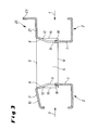
- the Fig. 1 shows a shelf support 1 of a storage rack, not shown here, in particular an automatic small parts warehouse, for storage of boxes and filled containers, which usually consists of four shelf supports 1, wherein the two front and the two rear shelf supports 1 are connected to each other via horizontal longitudinal beams 2 ,
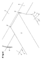
- the thus arranged parallel opposite longitudinal bars 2 are on the one hand on the operating side 3 and on the other hand at the shelf end 4 of the storage rack, being connected to each other via the bearing surface 5 forming cross members 6 (see Fig. 2 and 3 ).
- the longitudinal bars 2 have a cross-sectionally C-shaped profile and are provided with a lower, straight section 7 and an outwardly bent, formed upper section 8 having profile web 9.
- the longitudinal traverse can be provided at their ends with hook straps and hooked with these in the shelf supports 1;
- the straight section 7 is connected to the vertical shelf support 1 as shown, for example via a screw / nut combination.
- the curved upper section 8 is followed by the upper profile flange 10 with an inclined downwardly inclined surface 11 to the outside.
- the inclined surface 11 in this case represents an integrated insertion bevel, which allows a simple and easy pushing the boxes or containers on the bearing surface 5 of the cross member 6 and thus in the shelf.
- slot-shaped openings 12 are formed, which extend from the bent upper portion 8 to the lower straight portion 7 and serve to receive the cross member 6.
- the cross member 6 are formed in profile U-shaped and their vertical side walls 13, 14 are provided at the two front ends 15, 16 with vertically extending hooking openings 17, 18, which after immersion in the slot-shaped openings 12 of the longitudinal beams 2, the profile web engage behind.
- the cross members 6 are thus secured against movement in the longitudinal direction between the two longitudinal beams 2 (cf. Fig. 4 and 5 ).
- the bearing surface 5 is after hooking the cross member 6 at a height level with the longitudinal beams 2, so that the complete height of a shelf for the storage of goods is available.
- Fig. 2 has arranged at the end of the shelf 4 longitudinal beam 2 connected to the inclined surface 11, upwardly projecting push-through protection 19 in the form of an angle. This prevents the items to be stored from being pushed too far in the rack and subsequently falling out at the rear of the shelf.
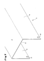
- the upper profile flange 21 extends horizontally and parallel to the lower profile flange 22 and its free end 23 is angled vertically upwards, which also provides a push-through.
Abstract
Description
Die Erfindung betrifft ein Lagerregal, insbesondere automatisches Kleinteilelager, umfassend vertikal angeordnete vordere und hintere Regalstützen mit an den Regalstützen vorne und hinten befestigten Längstraversen und Querträgern, die an den Längstraversen senkrecht zu diesen angebracht sind und Tragflächen aufweisen.The invention relates to a storage rack, in particular automatic small parts storage, comprising vertically arranged front and rear shelf supports with attached to the shelf supports front and rear longitudinal beams and cross members, which are mounted on the longitudinal beams perpendicular to these and have wings.
Bei den im Stand der Technik hinlänglich bekannten Kleinteilelagern, insbesondere automatischen Mehrplatz Kleinteilelagern, werden Kartons mit darin enthaltenen Gütern oder auch nach oben offene Kunststoff- oder Metallbehälter, in denen sich Einzelwaren befinden, sowohl hintereinander als auch nebeneinander liegend in den Regalfächern gelagert.In the well-known in the art small parts warehouses, especially automatic multi-location small parts warehouses, cartons are stored with goods contained therein or upwardly open plastic or metal containers in which are individual goods, both one behind the other and lying side by side in the shelves.
Die mit den Längstraversen verbundenen Querträger, z.B. Profilböden, stellen dabei die Tragflächen für die Kartons bzw. Behälter bereit.The cross beams connected to the longitudinal beams, e.g. Profile bottoms, thereby provide the wings for the boxes or containers ready.
Zur Anbringung der Querträger an den Längstraversen ist es durch die
Aus der
Dadurch ergibt sich zwar eine drehstabile Verbindung zwischen Längsträger und Querträger, allerdings mit dem Nachteil eines Höhenverlustes zwischen den vertikal übereinander liegenden Regalfächern, da die Querträger auf den Längsträgern aufliegen.Although this results in a rotationally stable connection between the side member and cross member, but with the disadvantage of a loss of height between the vertically stacked shelves, since the cross member rest on the side rails.
Desweiteren ist es im Stand der Technik bekannt, die Bestückungs- bzw. Bedienungsseite des Lagerregals mit Einführschrägen auszubilden. Wenn das Lagerregal, wie zuvor beschrieben, Querträger aufweist, die den höchsten Punkt des Fachbodens darstellen, ist eine Befestigung der Einfuhrschräge nur an den Querträgern selbst als separates Bauteil möglich, nicht jedoch an den Längstraversen. Die Einfuhrschrägen werden als an den Querträgern nach unten abgebogene Laschen, die mit einer Bohrung versehen sind, ausgebildet. Die Bohrung dient hierbei zur Fixierung der Querträger an der Längstraverse mittels einer Schraube.Furthermore, it is known in the art to form the placement or operating side of the storage rack with insertion bevels. If the storage rack, as described above, cross members, which represent the highest point of the shelf, an attachment of the import slope is only possible on the cross members themselves as a separate component, but not on the longitudinal bars. The import bevels are formed as at the cross beams bent down tabs, which are provided with a bore formed. The bore serves to fix the cross member to the longitudinal beam by means of a screw.
Um zu verhindern, dass die Kartons oder Behälter aus dem Regalfach nach hinten herausfallen können, ist es bekannt, an dem von der Bestückungsseite des Regals entfernten, hinteren Ende des Querträgers eine vertikal nach oben abgebogene Lasche als Durchschubsicherung vorzusehen. Der Querträger weist somit unterschiedlich ausgebildete Enden auf.In order to prevent the cartons or containers from falling out of the shelf to the rear, it is known to provide at the remote from the component side of the shelf, the rear end of the cross member a vertically upwardly bent tab as Durchschubsicherung. The cross member thus has differently shaped ends.
Durch die unterschiedlichen Enden der Querträger, einerseits mit Einfuhrschräge und andererseits mit Durchschubsicherung, sowie teilweise verschachtelter Querschnittsgeometrie der Traversenprofile, müssen die Querträger in einem aufwendigen Herstellungsverfahren gefertigt werden und verursachen somit höhere Produktionskosten.Due to the different ends of the cross member, on the one hand with an import slope and on the other hand with Durchschubsicherung, and partially nested cross-sectional geometry the truss profiles, the cross member must be made in a complex manufacturing process and thus cause higher production costs.
Der Erfindung liegt die Aufgabe zugrunde, bei einem Lagerregal der eingangs genannten Art die Längstraversen und die Querträger durch Ausbildung mit einer einfachen Geometrie kostengünstig herzustellen und gleichwohl deren Tragfähigkeit zu steigern sowie auch eine einfache Montage zu ermöglichen.The invention is based on the object in a storage rack of the type mentioned in the longitudinal beams and the cross member by training with a simple geometry inexpensive to manufacture and nonetheless to increase their capacity and to allow easy installation.
Diese Aufgabe wird erfindungsgemäß dadurch gelöst, dass im Querschnitt C-förmige Längstraversen mit einem einen unteren, geraden Teilabschnitt und einen nach außen hin abgebogenen, oberen Teilabschnitt aufweisenden Profilsteg ausgebildet sind und sich dem gebogenen oberen Teilabschnitt ein oberer Profilflansch mit einer nach außen abwärts geneigten Schrägfläche anschließt. Durch den nach unten abgewinkelten, oberen Profilflansch der Längstraverse wird eine permanente Einfuhrschräge bereitgestellt, über die Kartons, Behälter oder dergleichen barrierefrei und einfach auf die sich anschließenden Querträger des Regalfachs geschoben werden können. Die Einfuhrschräge ist damit fest in den Längstraversen integriert, so dass eine zusätzliche Montage eines abgewinkelten oder geneigten Bauteils als Einfuhrschräge, welches einzeln montiert werden müsste, entfällt.This object is achieved in that in cross-section C-shaped longitudinal beams with a lower, straight portion and an outwardly bent, upper portion having profiled web are formed and the curved upper portion of an upper profile flange with an outwardly inclined downward sloping surface followed. Due to the downwardly angled, upper profile flange of the longitudinal beam, a permanent insertion bevel is provided, over which boxes, containers or the like barrier-free and can be easily pushed onto the adjoining cross member of the shelf. The import slope is thus firmly integrated in the longitudinal beams, so that an additional installation of an angled or inclined component as an import slope, which would have to be mounted individually eliminated.
Eine bevorzugte Ausgestaltung der Erfindung sieht vor, dass die Profilstege der Längstraversen mit sich vom abgebogenen oberen Teilabschnitt bis in den geraden unteren Teilabschnitt erstreckenden, schlitzförmigen Öffnungen versehen sind. Dadurch, dass die schlitzförmigen Öffnungen, die zur Aufnahme von Querträgern dienen, im stabilen und durchgehenden Profilsteg angeordnet sind, erfahren die Längstraversen eine nur geringe Schwächung ihres C-förmigen Profilquerschnitts, wodurch deren Durchbiegung bei Belastung wesentlich reduziert und somit die Tragfähigkeit erhöht wird. Damit einhergehend ist weiterhin eine Reduzierung der Wandstärken der Längstraversen möglich, was zu einem Einsparpotential bei den Materialkosten führt.A preferred embodiment of the invention provides that the profile webs of the longitudinal beams are provided with extending from the bent upper portion to the straight lower portion extending slot-shaped openings. The fact that the slot-shaped openings, which serve to receive cross beams, are arranged in a stable and continuous profile web, the longitudinal beams undergo only a small weakening of their C-shaped profile cross-section, whereby their deflection is significantly reduced under load and thus the load capacity is increased. This is accompanied by a reduction the wall thicknesses of the longitudinal beams possible, resulting in a savings in material costs.
Ferner ermöglichen die bereits im oberen, abgebogenen Teilabschnitt des Profilsteges beginnenden und somit nach oben hin freiliegenden schlitzförmigen Öffnungen eine nachträgliche, d.h. nach der Montage und Verbindung der Regalstützen mit den Längstraversen, Einbringung der Querträger des Regals in die schlitzförmigen Öffnungen, nämlich durch einfaches Einstecken.Furthermore, the slot-shaped openings already beginning in the upper, bent subsection of the profile web and thus exposed upwards make it possible to create a subsequent, ie. after assembly and connection of the shelf supports with the longitudinal beams, introduction of the cross member of the shelf in the slot-shaped openings, namely by simply plugging.
Dazu sind die Querträger erfindungsgemäß U- / C-förmig oder dergleichen profiliert ausgebildet und ihre Seitenwangen sind am vorderen und am hinteren Ende des Querträgers mit vertikal verlaufenden Einhakausnehmungen zur Verbindung mit den schlitzförmigen Öffnungen der Längstraversen versehen. Eine die beiden Seitenwangen verbindende Stegfläche bildet dabei die Tragauflage für die einzulagernden Kartons bzw. Behälter. Über die Einhakausnehmungen, die nach dem Eintauchen in die schlitzförmigen Öffnungen den Profilsteg im inneren der C-förmigen Längstraverse hintergreifen, ist der Querträger sowohl in Längs- als auch in Querrichtung bewegungssicher in den schlitzförmigen Öffnungen der Längstraversen arretiert. Die schlitzförmigen Öffnungen sind hierbei in regelmäßigen Abständen, d.h. im Rastermaß in den Längstraversen vorgesehen, wobei das Rastermaß auf die Breite der Querträger und somit dem sich daraus ergebenden Abstand der Einhakausnehmungen voneinander abgestimmt ist.For this purpose, the cross member according to the invention U- / C-shaped or the like profiled formed and their side cheeks are provided at the front and at the rear end of the cross member with vertically extending Einhakausnehmungen for connection to the slot-shaped openings of the longitudinal bars. A web surface connecting the two side cheeks forms the supporting support for the boxes or containers to be stored. About the Einhakausnehmungen, which engage behind the profile web in the interior of the C-shaped longitudinal bar after immersion in the slot-shaped openings, the cross member is locked both in the longitudinal and in the transverse direction safe movement in the slot-shaped openings of the longitudinal bars. The slot-shaped openings are in this case at regular intervals, i. provided in the grid in the longitudinal beams, wherein the grid dimension is matched to the width of the cross member and thus the resulting distance of Einhakausnehmungen from each other.
Die Höhe der vertikalen Einhakausnehmungen in den Seitenwangen der Querträger ist so gewählt, dass nach dem Einlegen bzw. Einhaken des Querträgers dieser bündig auf einer Höhe mit den Längstraversen liegt, wodurch die gesamte Höhe des Regalfachs für die Einlagerung von Gütern zur Verfügung steht.The height of the vertical Einhakausnehmungen in the side cheeks of the cross member is chosen so that after inserting or hooking the cross member, this is flush with the longitudinal beams, whereby the entire height of the shelf is available for the storage of goods.
Eine weitere vorteilhafte Ausgestaltung der Erfindung sieht vor, dass die hintere Längstraverse auf der Schrägfläche ihres nach unten geneigten Profilflansches mit einer nach oben hin vorkragenden Durchschubsicherung versehen ist. Die hintere, der Bedienseite des Lagerregals gegenüberliegende Längstraverse ist von ihrer Geometrie her baugleich mit der vorderen Längstraverse, hier auf der Einfuhrschräge lediglich mit einer fest oder lösbar verbundenen Durchschubsicherung, beispielsweise ein Winkel oder dergleichen anschraubbares oder anschweissbares Bauteil, versehen. Damit wird verhindert, dass beim Befüllen der Regalfächer hintereinander eingeschobene Kartons bzw. Behälter am Ende des Regalfachs nach hinten herausfallen können.A further advantageous embodiment of the invention provides that the rear longitudinal beam on the inclined surface of its downwardly inclined profile flange an upwardly projecting Durchschubsicherung is provided. The rear, the operating side of the storage rack opposite longitudinal beam is structurally similar to the front longitudinal beam, here on the import slope only with a fixed or releasably connected Durchschubsicherung, for example, an angle or the like screwed or weldable component provided. This prevents that when filling the shelves one behind the other inserted boxes or containers at the end of the shelf can fall out to the rear.
Eine alternative Ausgestaltung der Erfindung sieht zur Bereitstellung einer Durchschubsicherung vor, dass der obere Profilflansch der hinteren Längstraverse horizontal und parallel zum unteren Profilflansch verläuft und an seinem freien Ende senkrecht nach oben hin abgewinkelt ist. Somit ist die Durchschubsicherung integraler Bestandteil der das hintere Regalfachende markierenden Längstraverse, wodurch die Montage separater und einzeln auf den Längstraversen zu montierender Durchschubsicherungen entfällt.An alternative embodiment of the invention provides for providing a push-through protection that the upper profile flange of the rear longitudinal cross-member extends horizontally and parallel to the lower profile flange and is angled vertically upwards at its free end. Thus, the push-through protection is an integral part of the rear shelf end-marking longitudinal beam, whereby the installation of separate and individually to be mounted on the longitudinal bars Durchschubsicherungen deleted.
Weitere Einzelheiten und Vorteile der Erfindung ergeben sich aus den Ansprüchen und der nachfolgenden Beschreibung von in den Zeichnungen dargestellten Ausführungsbeispielen des Gegenstandes der Erfindung. Es zeigen:
- Fig. 1
- als Einzelheit eines Lagerregals ausschnittsweise eine C-förmige Längstra- verse, die einerseits über ihren Profilsteg mit einer Regalstütze verbunden ist und in die andererseits in dem Profilsteg ein die Lagerfläche bildender Querträger eingehakt ist;
- Fig. 2
- in einem Querschnitt eine vordere und eine hintere, jeweils baugleiche C- förmige Längstraverse eines Lagerregals, die über einen in den Längstra- versen eingehakten Querträger miteinander verbunden sind;
- Fig. 3
- eine Darstellung wie gemäß
Fig. 2 mit demgegenüber anders ausgebilde- ter, hinterer Längstraverse; - Fig. 4
- als Einzelheit in einer perspektivischen Ansicht von der dem Regalfach zu- gewandten Rückseite her gesehen eine Längstraverse mit in ihrem Profil- steg ausgebildeten, schlitzförmigen Öffnungen, in die ein Querträger ein- gehakt ist;
- Fig. 5
- die Längstraverse gemäß
Fig. 4 in einer perspektivischen Ansicht von der Vorderseite her gesehen; - Fig. 6
- in einer perspektivischen Darstellung eine Längstraverse mit mehreren dar- in eingehakten Querträgern; und
- Fig. 7
- in einer perspektivischen Teilansicht ein stirnseitiges Ende eines Querträg- res.
- Fig. 1
- as a detail of a storage rack a detail of a C-shaped Längstra- verse, which is connected on the one hand via its profile web with a rack support and in the other part in the profile web a bearing surface forming cross member is hooked;
- Fig. 2
- in a cross section, a front and a rear, in each case identical C-shaped longitudinal cross-section of a storage rack, which are connected to one another via a cross member hooked in the longitudinal strands;
- Fig. 3
- a representation as in accordance
Fig. 2 by contrast, a different rear crossbar; - Fig. 4
- seen in detail in a perspective view from the rear side facing the shelf, a longitudinal traverse with slot-shaped openings formed in its profile web, in which a cross member is hooked;
- Fig. 5
- the longitudinal beam according to
Fig. 4 seen in a perspective view from the front side; - Fig. 6
- in a perspective view of a longitudinal beam with a plurality of cross-beams hooked therein; and
- Fig. 7
- in a perspective partial view of an end face of a cross member.
Die
Die somit parallel gegenüberliegend angeordneten Längstraversen 2 befinden sich dabei einerseits an der Bedienseite 3 und andererseits am Regalfachende 4 des Lagerregals, wobei sie über die Lagerfläche 5 bildenden Querträgern 6 miteinander verbunden sind (vgl. hierzu
Die Längstraversen 2 besitzen ein im Querschnitt C-förmiges Profil und sind mit einem einen unteren, geraden Teilabschnitt 7 und einen nach außen hin abgebogenen, oberen Teilabschnitt 8 aufweisenden Profilsteg 9 ausgebildet. Die Längstraverse kann an ihren Enden mit Hakenlaschen versehen sein und mit diesen in die Regalstützen 1 eingehängt werden; optional ist der gerade Teilabschnitt 7 wie dargestellt mit der vertikalen Regalstütze 1 verbunden, beispielsweise über eine Schrauben/Mutternkombination. Dem gebogenen oberen Teilabschnitt 8 schließt sich der obere Profilflansch 10 mit einer nach außen abwärts geneigten Schrägfläche 11 an. Die Schrägfläche 11 stellt hierbei eine integrierte Einfuhrschräge dar, die ein einfaches und leichtes Aufschieben der Kartons bzw. Behälter auf die Lagerfläche 5 der Querträger 6 und somit in das Regalfach ermöglicht.The
Im Profilsteg 9 der Längstraverse 2 sind schlitzförmige Öffnungen 12 ausgebildet, die sich vom abgebogenen oberen Teilabschnitt 8 bis in den unteren geraden Teilabschnitt 7 erstrecken und zur Aufnahme der Querträger 6 dienen.In the
Die Querträger 6 sind im Profil U-förmig ausgebildet und ihre senkrechten Seitenwangen 13, 14 sind an den beiden stirnseitigen Enden 15, 16 mit vertikal verlaufenden Einhaköffnungen 17, 18 versehen, die nach dem Eintauchen in die schlitzförmigen Öffnungen 12 der Längstraversen 2 den Profilsteg 9 hintergreifen. Die Querträger 6 werden somit in Längsrichtung zwischen den beiden Längstraversen 2 bewegungssicher festgelegt (vgl. hierzu insbesondere die
Gleichzeitig werden die Seitenwangen 13, 14 in vertikaler Richtung von den schlitzförmigen Öffnungen 12 eingehaust, womit eine Verschiebung der Querträger 6, insbesondere bei Belastung, zur Seite hin wirkungsvoll verhindert wird.At the same time the
Die solchermaßen mit den Längstraversen 2 verbundenen Querträger 6, die in regelmäßigem Abstand parallel zueinander verlaufend in jedem Regalfach angeordnet sind, versteifen gleichzeitig auch die Längstraversen 2, was bewirkt, dass diese sich unter Last nicht verdrehen. Die Anbringung von zusätzlichen Druckstäben zur Stabilisierung der Längstraversen 2 ist somit nicht mehr erforderlich.The thus connected to the
Die Lagerfläche 5 liegt nach dem Einhaken der Querträger 6 auf einem Höhenniveau mit den Längstraversen 2, so dass die komplette Höhe eines Regalfachs für die Einlagerung von Gütern zur Verfügung steht.The bearing
Dadurch, dass die schlitzförmigen Öffnungen 12 bereits im oberen, abgebogenen Teilabschnitt des Profilsteges 9 ausgebildet sind, können die gegenüberliegenden Längstraversen 2 direkt bei der Montage des Lagerregals mit den Regalstützen 1 verschraubt und abschließend die Querträger 6 von oben her in die Längstraversen 2 eingehakt werden.The fact that the slot-shaped
Wie der
Bei einer in
- 11
- Regalstützeshelf support
- 22
- LängstraverseMain beam
- 33
- Bedienseiteoperating side
- 44
- RegalfachendeShelf end
- 55
- Lagerflächestorage area
- 66
- Querträgercrossbeam
- 77
- unterer Teilabschnittlower section
- 88th
- oberer Teilabschnittupper section
- 99
- Profilstegprofile web
- 1010
- oberer Profilflanschupper profile flange
- 1111
- Schrägflächesloping surface
- 1212
- schlitzförmige Öffnungslotted opening
- 1313
- Seitenwangeside cheek
- 1414
- Seitenwangeside cheek
- 1515
- vorderes Ende (Querträger)front end (cross member)
- 1616
- hinteres Ende (Querträger)rear end (cross member)
- 1717
- Einhakausnehmunglatching recess
- 1818
- Einhakausnehmunglatching recess
- 1919
- DurchschubsicherungPush-through stops
- 2020
- LängstraverseMain beam
- 2121
- oberer Profilflanschupper profile flange
- 2222
- unterer Profilflanschlower profile flange
- 2323
- freies abgewinkeltes Ende (oberer Profilflansch); Durchschubsicherungfree angled end (upper profile flange); Push-through stops
Claims (6)
dadurch gekennzeichnet,
dass im Querschnitt C-förmige Längstraversen (2) mit einem einen unteren, geraden Teilabschnitt (7) und einen nach außen hin abgebogenen, oberen Teilabschnitt (8) aufweisenden Profilsteg (9) ausgebildet sind und sich dem gebogenen oberen Teilabschnitt (8) ein oberer Profilflansch (10) mit einer nach außen abwärts geneigten Schrägfläche (11) anschließt.Storage rack, in particular automatic small parts storage, comprising vertically arranged front and rear shelf supports (1) with longitudinal supports (2) fastened to the shelf supports at the front and rear and cross members (6) which are attached to the longitudinal beams (2) perpendicular thereto and have wings;
characterized,
in that cross-section C-shaped longitudinal beams (2) are formed with a profiled web (9) having a lower, straight subsection (7) and an outwardly bent, upper subsection (8), and an upper upper curved section (8) Profile flange (10) with an outwardly downwardly inclined inclined surface (11) connects.
dadurch gekennzeichnet,
dass die Profilstege (9) der Längstraversen (2) mit sich vom abgebogenen oberen Teilabschnitt (8) bis in den geraden unteren Teilabschnitt (7) erstreckenden, schlitzförmigen Ausnehmungen (12) versehen sind.Storage rack according to claim 1,
characterized,
that the profile webs (9) of the longitudinal beams (2) extending from the bent with the upper portion (8) extends into the straight lower section (7), slot-shaped recesses (12) are provided.
dadurch gekennzeichnet,
dass die schlitzförmigen Öffnungen (12) in regelmäßigen Abständen zueinander angeordnet sind.Storage rack according to claim 2,
characterized,
in that the slot-shaped openings (12) are arranged at regular intervals from one another.
dadurch gekennzeichnet,
dass die Querträger (6) U- / C-förmig oder dergleichen profiliert ausgebildet sind und ihre Seitenwangen (13, 14) am vorderen und am hinteren Ende (15, 16) des Querträgers (6) vertikal verlaufende Einhakausnehmungen (17, 18) zur Verbindung mit den schlitzförmigen Öffnungen (12) der Längstraversen (2, 20) aufweisen.Storage rack according to one of claims 1 to 3,
characterized,
in that the cross members (6) are U-shaped / C-shaped or the like profiled and their side cheeks (13, 14) have hooking recesses (17, 18) running vertically at the front and at the rear end (15, 16) of the cross member (6) Connection with the slot-shaped openings (12) of the longitudinal bars (2, 20).
dadurch gekennzeichnet,
dass die hintere Längstraverse (2) auf der Schrägfläche (11) ihres nach unten geneigten Profilflansches (10) mit einer nach oben hin vorkragenden Durchschubsicherung (19) versehen ist.Storage rack according to one of claims 1 to 4,
characterized,
that the rear longitudinal beam (2) on the inclined surface (11) of its downward inclination Profilflansches (10) is provided with a projecting upwardly push-through protection (19).
dadurch gekennzeichnet,
dass der obere Profilflansch (21) der hinteren Längstraverse (20) horizontal und parallel zum unteren Profilflansch (22) verläuft und an seinem freien Ende (23) nach oben hin abgewinkelt ist.Storage rack according to one of claims 1 to 5,
characterized,
in that the upper profiled flange (21) of the rear longitudinal cross-member (20) extends horizontally and parallel to the lower profiled flange (22) and is angled upwards at its free end (23).
Priority Applications (1)
| Application Number | Priority Date | Filing Date | Title |
|---|---|---|---|
| PL10014094T PL2324732T3 (en) | 2009-11-20 | 2010-10-29 | Storage rack, in particular automatic small part storage |
Applications Claiming Priority (1)
| Application Number | Priority Date | Filing Date | Title |
|---|---|---|---|
| DE202009015784 | 2009-11-20 |
Publications (2)
| Publication Number | Publication Date |
|---|---|
| EP2324732A1 true EP2324732A1 (en) | 2011-05-25 |
| EP2324732B1 EP2324732B1 (en) | 2017-05-24 |
Family
ID=43608572
Family Applications (1)
| Application Number | Title | Priority Date | Filing Date |
|---|---|---|---|
| EP10014094.6A Active EP2324732B1 (en) | 2009-11-20 | 2010-10-29 | Storage rack, in particular automatic small part storage |
Country Status (4)
| Country | Link |
|---|---|
| EP (1) | EP2324732B1 (en) |
| DK (1) | DK2324732T3 (en) |
| ES (1) | ES2629468T3 (en) |
| PL (1) | PL2324732T3 (en) |
Cited By (3)
| Publication number | Priority date | Publication date | Assignee | Title |
|---|---|---|---|---|
| WO2013006879A2 (en) | 2011-07-08 | 2013-01-17 | Tgw Mechanics Gmbh | Rack storage system |
| WO2020001680A1 (en) * | 2018-06-28 | 2020-01-02 | Rickard Nilsson | Shelf element for a shelf system of a rack, extruded profile, shelf frame, shelf system and rack |
| WO2022048958A1 (en) * | 2020-09-01 | 2022-03-10 | Nedcon B.V. | Goods-storage rack |
Citations (4)
| Publication number | Priority date | Publication date | Assignee | Title |
|---|---|---|---|---|
| FR1439548A (en) * | 1965-06-30 | 1966-05-20 | Indive Gmbh | Shelving with assembled single elements |
| DE20315601U1 (en) | 2003-10-10 | 2003-12-11 | Nedcon Magazijninrichting B.V. | Storage rack for piece goods support element installed on cross member as extension to each piece goods lane and has width which in relation to longitudinal extent of cross member is small in comparison to width of piece goods |
| EP1559345A1 (en) * | 2004-01-28 | 2005-08-03 | Stow International N.V. | Storage system and components used therefor |
| DE102007056589B3 (en) | 2007-11-23 | 2009-06-04 | Bito-Lagertechnik Bittmann Gmbh | storage rack |
-
2010
- 2010-10-29 EP EP10014094.6A patent/EP2324732B1/en active Active
- 2010-10-29 ES ES10014094.6T patent/ES2629468T3/en active Active
- 2010-10-29 DK DK10014094.6T patent/DK2324732T3/en active
- 2010-10-29 PL PL10014094T patent/PL2324732T3/en unknown
Patent Citations (4)
| Publication number | Priority date | Publication date | Assignee | Title |
|---|---|---|---|---|
| FR1439548A (en) * | 1965-06-30 | 1966-05-20 | Indive Gmbh | Shelving with assembled single elements |
| DE20315601U1 (en) | 2003-10-10 | 2003-12-11 | Nedcon Magazijninrichting B.V. | Storage rack for piece goods support element installed on cross member as extension to each piece goods lane and has width which in relation to longitudinal extent of cross member is small in comparison to width of piece goods |
| EP1559345A1 (en) * | 2004-01-28 | 2005-08-03 | Stow International N.V. | Storage system and components used therefor |
| DE102007056589B3 (en) | 2007-11-23 | 2009-06-04 | Bito-Lagertechnik Bittmann Gmbh | storage rack |
Cited By (4)
| Publication number | Priority date | Publication date | Assignee | Title |
|---|---|---|---|---|
| WO2013006879A2 (en) | 2011-07-08 | 2013-01-17 | Tgw Mechanics Gmbh | Rack storage system |
| WO2020001680A1 (en) * | 2018-06-28 | 2020-01-02 | Rickard Nilsson | Shelf element for a shelf system of a rack, extruded profile, shelf frame, shelf system and rack |
| US11844445B2 (en) | 2018-06-28 | 2023-12-19 | Rickard Nilsson | Shelf element for a shelf system of a rack, extruded profile, shelf frame, shelf system and rack |
| WO2022048958A1 (en) * | 2020-09-01 | 2022-03-10 | Nedcon B.V. | Goods-storage rack |
Also Published As
| Publication number | Publication date |
|---|---|
| ES2629468T3 (en) | 2017-08-09 |
| DK2324732T3 (en) | 2017-09-11 |
| EP2324732B1 (en) | 2017-05-24 |
| PL2324732T3 (en) | 2017-10-31 |
Similar Documents
| Publication | Publication Date | Title |
|---|---|---|
| EP2487117B1 (en) | Palette | |
| EP0882660B1 (en) | Shelf for storage and order picking | |
| DE202007011927U1 (en) | Product display system | |
| EP2389836B1 (en) | Vending shelf | |
| EP2062502B1 (en) | Shelf | |
| EP2324732B1 (en) | Storage rack, in particular automatic small part storage | |
| EP1426521B1 (en) | Facade for walls | |
| EP1205128B1 (en) | Shelf | |
| EP2684820B1 (en) | Shelf | |
| EP2750546A2 (en) | Furniture unit | |
| WO2010141970A1 (en) | Wall covering | |
| DE102013108751A1 (en) | Runge for a commercial vehicle | |
| EP2826365B1 (en) | Fence element | |
| WO2002067725A1 (en) | Shelf system | |
| DE202005012080U1 (en) | Shelf bracket has horizontal section which supports shelf and vertical section, to which resilient horizontal clip is attached, hook on opposite side which curves upwards fitting into profiled support rail | |
| EP1066774B1 (en) | Shelving unit | |
| EP2226272B1 (en) | Shelving system | |
| DE102014106539B4 (en) | Traverse for a cabinet | |
| DE202009015200U1 (en) | balcony design | |
| EP3813600A1 (en) | Shelf element for a shelf system of a rack, extruded profile, shelf frame, shelf system and rack | |
| DE7834753U1 (en) | SHELVING, IN PARTICULAR PALLET SHELVES | |
| DE202008011638U1 (en) | Shelving system for storing objects | |
| DE1753832A1 (en) | DRAWER CABINET | |
| WO2015082266A1 (en) | Rack, in particular free-standing rack | |
| DE19835112A1 (en) | Shelving unit |
Legal Events
| Date | Code | Title | Description |
|---|---|---|---|
| PUAI | Public reference made under article 153(3) epc to a published international application that has entered the european phase |
Free format text: ORIGINAL CODE: 0009012 |
|
| AK | Designated contracting states |
Kind code of ref document: A1 Designated state(s): AL AT BE BG CH CY CZ DE DK EE ES FI FR GB GR HR HU IE IS IT LI LT LU LV MC MK MT NL NO PL PT RO RS SE SI SK SM TR |
|
| AX | Request for extension of the european patent |
Extension state: BA ME |
|
| 17P | Request for examination filed |
Effective date: 20111013 |
|
| R17P | Request for examination filed (corrected) |
Effective date: 20111013 |
|
| 17Q | First examination report despatched |
Effective date: 20160128 |
|
| GRAP | Despatch of communication of intention to grant a patent |
Free format text: ORIGINAL CODE: EPIDOSNIGR1 |
|
| INTG | Intention to grant announced |
Effective date: 20161216 |
|
| GRAS | Grant fee paid |
Free format text: ORIGINAL CODE: EPIDOSNIGR3 |
|
| GRAA | (expected) grant |
Free format text: ORIGINAL CODE: 0009210 |
|
| AK | Designated contracting states |
Kind code of ref document: B1 Designated state(s): AL AT BE BG CH CY CZ DE DK EE ES FI FR GB GR HR HU IE IS IT LI LT LU LV MC MK MT NL NO PL PT RO RS SE SI SK SM TR |
|
| REG | Reference to a national code |
Ref country code: GB Ref legal event code: FG4D Free format text: NOT ENGLISH |
|
| REG | Reference to a national code |
Ref country code: CH Ref legal event code: EP |
|
| REG | Reference to a national code |
Ref country code: IE Ref legal event code: FG4D Free format text: LANGUAGE OF EP DOCUMENT: GERMAN |
|
| REG | Reference to a national code |
Ref country code: AT Ref legal event code: REF Ref document number: 895569 Country of ref document: AT Kind code of ref document: T Effective date: 20170615 |
|
| REG | Reference to a national code |
Ref country code: DE Ref legal event code: R096 Ref document number: 502010013643 Country of ref document: DE |
|
| REG | Reference to a national code |
Ref country code: CH Ref legal event code: NV Representative=s name: SCHMAUDER AND PARTNER AG PATENT- UND MARKENANW, CH |
|
| REG | Reference to a national code |
Ref country code: ES Ref legal event code: FG2A Ref document number: 2629468 Country of ref document: ES Kind code of ref document: T3 Effective date: 20170809 |
|
| REG | Reference to a national code |
Ref country code: SE Ref legal event code: TRGR |
|
| REG | Reference to a national code |
Ref country code: NL Ref legal event code: FP |
|
| REG | Reference to a national code |
Ref country code: DK Ref legal event code: T3 Effective date: 20170905 |
|
| REG | Reference to a national code |
Ref country code: NO Ref legal event code: T2 Effective date: 20170524 |
|
| REG | Reference to a national code |
Ref country code: LT Ref legal event code: MG4D |
|
| REG | Reference to a national code |
Ref country code: FR Ref legal event code: PLFP Year of fee payment: 8 |
|
| PG25 | Lapsed in a contracting state [announced via postgrant information from national office to epo] |
Ref country code: HR Free format text: LAPSE BECAUSE OF FAILURE TO SUBMIT A TRANSLATION OF THE DESCRIPTION OR TO PAY THE FEE WITHIN THE PRESCRIBED TIME-LIMIT Effective date: 20170524 Ref country code: GR Free format text: LAPSE BECAUSE OF FAILURE TO SUBMIT A TRANSLATION OF THE DESCRIPTION OR TO PAY THE FEE WITHIN THE PRESCRIBED TIME-LIMIT Effective date: 20170825 Ref country code: LT Free format text: LAPSE BECAUSE OF FAILURE TO SUBMIT A TRANSLATION OF THE DESCRIPTION OR TO PAY THE FEE WITHIN THE PRESCRIBED TIME-LIMIT Effective date: 20170524 |
|
| PG25 | Lapsed in a contracting state [announced via postgrant information from national office to epo] |
Ref country code: IS Free format text: LAPSE BECAUSE OF FAILURE TO SUBMIT A TRANSLATION OF THE DESCRIPTION OR TO PAY THE FEE WITHIN THE PRESCRIBED TIME-LIMIT Effective date: 20170924 Ref country code: LV Free format text: LAPSE BECAUSE OF FAILURE TO SUBMIT A TRANSLATION OF THE DESCRIPTION OR TO PAY THE FEE WITHIN THE PRESCRIBED TIME-LIMIT Effective date: 20170524 Ref country code: RS Free format text: LAPSE BECAUSE OF FAILURE TO SUBMIT A TRANSLATION OF THE DESCRIPTION OR TO PAY THE FEE WITHIN THE PRESCRIBED TIME-LIMIT Effective date: 20170524 Ref country code: BG Free format text: LAPSE BECAUSE OF FAILURE TO SUBMIT A TRANSLATION OF THE DESCRIPTION OR TO PAY THE FEE WITHIN THE PRESCRIBED TIME-LIMIT Effective date: 20170824 |
|
| PG25 | Lapsed in a contracting state [announced via postgrant information from national office to epo] |
Ref country code: RO Free format text: LAPSE BECAUSE OF FAILURE TO SUBMIT A TRANSLATION OF THE DESCRIPTION OR TO PAY THE FEE WITHIN THE PRESCRIBED TIME-LIMIT Effective date: 20170524 Ref country code: SK Free format text: LAPSE BECAUSE OF FAILURE TO SUBMIT A TRANSLATION OF THE DESCRIPTION OR TO PAY THE FEE WITHIN THE PRESCRIBED TIME-LIMIT Effective date: 20170524 Ref country code: EE Free format text: LAPSE BECAUSE OF FAILURE TO SUBMIT A TRANSLATION OF THE DESCRIPTION OR TO PAY THE FEE WITHIN THE PRESCRIBED TIME-LIMIT Effective date: 20170524 |
|
| REG | Reference to a national code |
Ref country code: DE Ref legal event code: R097 Ref document number: 502010013643 Country of ref document: DE |
|
| PG25 | Lapsed in a contracting state [announced via postgrant information from national office to epo] |
Ref country code: SM Free format text: LAPSE BECAUSE OF FAILURE TO SUBMIT A TRANSLATION OF THE DESCRIPTION OR TO PAY THE FEE WITHIN THE PRESCRIBED TIME-LIMIT Effective date: 20170524 |
|
| PLBE | No opposition filed within time limit |
Free format text: ORIGINAL CODE: 0009261 |
|
| STAA | Information on the status of an ep patent application or granted ep patent |
Free format text: STATUS: NO OPPOSITION FILED WITHIN TIME LIMIT |
|
| 26N | No opposition filed |
Effective date: 20180227 |
|
| PG25 | Lapsed in a contracting state [announced via postgrant information from national office to epo] |
Ref country code: SI Free format text: LAPSE BECAUSE OF FAILURE TO SUBMIT A TRANSLATION OF THE DESCRIPTION OR TO PAY THE FEE WITHIN THE PRESCRIBED TIME-LIMIT Effective date: 20170524 Ref country code: MC Free format text: LAPSE BECAUSE OF FAILURE TO SUBMIT A TRANSLATION OF THE DESCRIPTION OR TO PAY THE FEE WITHIN THE PRESCRIBED TIME-LIMIT Effective date: 20170524 |
|
| REG | Reference to a national code |
Ref country code: IE Ref legal event code: MM4A |
|
| PG25 | Lapsed in a contracting state [announced via postgrant information from national office to epo] |
Ref country code: LU Free format text: LAPSE BECAUSE OF NON-PAYMENT OF DUE FEES Effective date: 20171029 |
|
| PG25 | Lapsed in a contracting state [announced via postgrant information from national office to epo] |
Ref country code: MT Free format text: LAPSE BECAUSE OF FAILURE TO SUBMIT A TRANSLATION OF THE DESCRIPTION OR TO PAY THE FEE WITHIN THE PRESCRIBED TIME-LIMIT Effective date: 20170524 |
|
| REG | Reference to a national code |
Ref country code: FR Ref legal event code: PLFP Year of fee payment: 9 |
|
| PG25 | Lapsed in a contracting state [announced via postgrant information from national office to epo] |
Ref country code: IE Free format text: LAPSE BECAUSE OF NON-PAYMENT OF DUE FEES Effective date: 20171029 |
|
| PG25 | Lapsed in a contracting state [announced via postgrant information from national office to epo] |
Ref country code: HU Free format text: LAPSE BECAUSE OF FAILURE TO SUBMIT A TRANSLATION OF THE DESCRIPTION OR TO PAY THE FEE WITHIN THE PRESCRIBED TIME-LIMIT; INVALID AB INITIO Effective date: 20101029 |
|
| PG25 | Lapsed in a contracting state [announced via postgrant information from national office to epo] |
Ref country code: CY Free format text: LAPSE BECAUSE OF NON-PAYMENT OF DUE FEES Effective date: 20170524 |
|
| PG25 | Lapsed in a contracting state [announced via postgrant information from national office to epo] |
Ref country code: MK Free format text: LAPSE BECAUSE OF FAILURE TO SUBMIT A TRANSLATION OF THE DESCRIPTION OR TO PAY THE FEE WITHIN THE PRESCRIBED TIME-LIMIT Effective date: 20170524 |
|
| PG25 | Lapsed in a contracting state [announced via postgrant information from national office to epo] |
Ref country code: TR Free format text: LAPSE BECAUSE OF FAILURE TO SUBMIT A TRANSLATION OF THE DESCRIPTION OR TO PAY THE FEE WITHIN THE PRESCRIBED TIME-LIMIT Effective date: 20170524 |
|
| PG25 | Lapsed in a contracting state [announced via postgrant information from national office to epo] |
Ref country code: PT Free format text: LAPSE BECAUSE OF FAILURE TO SUBMIT A TRANSLATION OF THE DESCRIPTION OR TO PAY THE FEE WITHIN THE PRESCRIBED TIME-LIMIT Effective date: 20170524 |
|
| PG25 | Lapsed in a contracting state [announced via postgrant information from national office to epo] |
Ref country code: AL Free format text: LAPSE BECAUSE OF FAILURE TO SUBMIT A TRANSLATION OF THE DESCRIPTION OR TO PAY THE FEE WITHIN THE PRESCRIBED TIME-LIMIT Effective date: 20170524 |
|
| PGFP | Annual fee paid to national office [announced via postgrant information from national office to epo] |
Ref country code: NO Payment date: 20230313 Year of fee payment: 13 Ref country code: FR Payment date: 20230321 Year of fee payment: 13 Ref country code: FI Payment date: 20230321 Year of fee payment: 13 Ref country code: ES Payment date: 20230228 Year of fee payment: 13 Ref country code: DK Payment date: 20230314 Year of fee payment: 13 Ref country code: CZ Payment date: 20230303 Year of fee payment: 13 Ref country code: CH Payment date: 20230328 Year of fee payment: 13 Ref country code: AT Payment date: 20230322 Year of fee payment: 13 |
|
| PGFP | Annual fee paid to national office [announced via postgrant information from national office to epo] |
Ref country code: SE Payment date: 20230308 Year of fee payment: 13 Ref country code: PL Payment date: 20230308 Year of fee payment: 13 Ref country code: GB Payment date: 20230227 Year of fee payment: 13 Ref country code: DE Payment date: 20230321 Year of fee payment: 13 Ref country code: BE Payment date: 20230321 Year of fee payment: 13 |
|
| P01 | Opt-out of the competence of the unified patent court (upc) registered |
Effective date: 20230517 |
|
| PGFP | Annual fee paid to national office [announced via postgrant information from national office to epo] |
Ref country code: NL Payment date: 20230321 Year of fee payment: 13 |
|
| PGFP | Annual fee paid to national office [announced via postgrant information from national office to epo] |
Ref country code: IT Payment date: 20230328 Year of fee payment: 13 |