EP1523797B1 - Moteur lectrique pour machine-outil manuelle - Google Patents
Moteur lectrique pour machine-outil manuelle Download PDFInfo
- Publication number
- EP1523797B1 EP1523797B1 EP03729974.0A EP03729974A EP1523797B1 EP 1523797 B1 EP1523797 B1 EP 1523797B1 EP 03729974 A EP03729974 A EP 03729974A EP 1523797 B1 EP1523797 B1 EP 1523797B1
- Authority
- EP
- European Patent Office
- Prior art keywords
- electric motor
- brush holder
- brush
- opening
- latching cap
- Prior art date
- Legal status (The legal status is an assumption and is not a legal conclusion. Google has not performed a legal analysis and makes no representation as to the accuracy of the status listed.)
- Expired - Lifetime
Links
- OKTJSMMVPCPJKN-UHFFFAOYSA-N Carbon Chemical compound [C] OKTJSMMVPCPJKN-UHFFFAOYSA-N 0.000 claims description 19
- 229910052799 carbon Inorganic materials 0.000 claims description 19
- 210000002105 tongue Anatomy 0.000 claims description 8
- 239000002184 metal Substances 0.000 claims description 3
- 210000002414 leg Anatomy 0.000 description 6
- 210000000689 upper leg Anatomy 0.000 description 1
Images
Classifications
-
- H—ELECTRICITY
- H02—GENERATION; CONVERSION OR DISTRIBUTION OF ELECTRIC POWER
- H02K—DYNAMO-ELECTRIC MACHINES
- H02K15/00—Processes or apparatus specially adapted for manufacturing, assembling, maintaining or repairing of dynamo-electric machines
-
- H—ELECTRICITY
- H01—ELECTRIC ELEMENTS
- H01R—ELECTRICALLY-CONDUCTIVE CONNECTIONS; STRUCTURAL ASSOCIATIONS OF A PLURALITY OF MUTUALLY-INSULATED ELECTRICAL CONNECTING ELEMENTS; COUPLING DEVICES; CURRENT COLLECTORS
- H01R39/00—Rotary current collectors, distributors or interrupters
- H01R39/02—Details for dynamo electric machines
- H01R39/38—Brush holders
- H01R39/385—Means for mechanical fixation of the brush holder
-
- H—ELECTRICITY
- H02—GENERATION; CONVERSION OR DISTRIBUTION OF ELECTRIC POWER
- H02K—DYNAMO-ELECTRIC MACHINES
- H02K5/00—Casings; Enclosures; Supports
- H02K5/04—Casings or enclosures characterised by the shape, form or construction thereof
- H02K5/14—Means for supporting or protecting brushes or brush holders
- H02K5/143—Means for supporting or protecting brushes or brush holders for cooperation with commutators
- H02K5/148—Slidably supported brushes
Definitions
- the present invention is based on an electric motor according to the preamble of claim 1.
- each carbon brush is connected to a locking cap, which can be locked in a cover-like manner with a shaft-like brush holder and which presses the carbon brush into the interior of the brush holder, thereby contacting the carbon brush spring-biased with the rotor or with its collector.
- the removal of the carbon brush is done by lifting the locking cap of the brush holder and their common removal through the service opening to the outside.
- the release of the locking cap of the brush holder and the removal of the carbon brush is cumbersome and time consuming.
- the present invention with the features of claim 1 has the advantage that the carbon brush is even faster and safer removable from the brush holder and interchangeable with a new.
- the brush holder on a central lid for engaging over the end face of the brush holder, which carries U-legs on opposite sides, wherein the engagement means as an opening of a U-leg for engagement of a screwdriver blade or the like. Is formed.
- the locking cap is designed as a stamped sheet metal part, it is inexpensive to produce and easy.
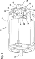
- Fig. 1 shows an electric motor 10 with a cylinder jacket-like, designed as a sheet metal outer shell 12, which carries inside a rotor, not shown, whose motor shaft 14 on the end faces of the motor 10 to the outside.
- the electric motor 10 carries at the end a brush plate 16, which is flanged to the outer outer shell 12 is. This brush plate 16 will pass centrally from the other end of the motor shaft 14.
- the brush holders 20 are externally closed by a respective locking cap 22, which consists of a cover 24 with two lateral legs 26, 28, which hold by means of spring tongues 44 on the side of the brush holder 20 latching.
- the one leg 28 carries an angled region 32 with a cross-slot-like opening 34 as a mounting means 30 for engagement of a blade of a screwdriver 46.
- the locking cap 22 carries on its cover an engagement slot 36 for entry of a slot screwdriver. This can be arranged centrally but also elsewhere in the locking cap 22.
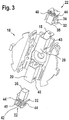
- the carbon brush 38 hangs on a cable strand 42 (FIG. Fig. 3 ), wherein between the cover 24 and brush a prestressed spring 40 is seated. This presses the carbon brush 38 in the brush holder 20 inwardly in the direction of the rotor or its collector away from the lid 24th
- the legs 26, 28 each carry a surface-free punched spring tongue 44, each biased inwardly toward the brush holder 20 out of the thigh plane protrudes and the locking cap 22 captive on the brush holder 20 holds.
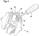
- a Phillips screwdriver 46 is guided with its blade tip in the correspondingly profiled opening 34 of the locking cap 22. Thereafter, the locking cap 22 is removable by turning or pivoting the screwdriver 46 from the brush holder 20, wherein the carbon brush 38 by biasing the spring 40 (FIG. Fig. 3 ) automatically follows.
- a Phillips screwdriver 46 may be inserted into the engagement slot 36 of the detent cap 22 and removed by turning it off along with the carbon brush 38.
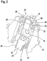
- Fig. 2 shows the brush plate 16 as a detail, in which case the two mirror-symmetrical brush holders 20 with the operatively attached thereto locking caps 22 are visible, which are electrically connected via the cable strand 42 with the unrecognizable carbon brushes 38 and hold them in the brush holder 20 positionally secure.
- each leg 28 of the locking cap 22 with the cross-slot-like opening 34.
- a bearing bore 19 can be seen centrally in the brush plate 16, which serves to pass through the motor shaft 14 in the assembled motor 10.
- the contact tongue 18 of the brush holder 20 for connecting a power cable is clearly visible.
- Fig. 3 shows Fig. 2 as an exploded view, wherein the carbon brushes 38 are recognizable in their association with the locking cap 22, in particular with the prestressed between the cap 22 and carbon brush 38 along the cable strand 42 spring 40.
- Fig. 2 Beyond locking openings 45 laterally visible in the brush sockets 20, in which the spring tongues 44 of the locking caps 22 engage in proper assembly and hold the locking caps 22 captive on the brush sockets 20.
- FIG. 4 shows over the FIGS. 1 to 3
- the leg 28 rises with its tongue 44 from the locking opening 45 and the locking cap 22 can be removed along the brush holder 20, where you follow the carbon brush 38 together with the spring 40 and the cable strand 42 and can be exchanged for a new carbon brush 38 with spring 40, cable strand 42 and cap 20.
Landscapes
- Engineering & Computer Science (AREA)
- Power Engineering (AREA)
- Manufacturing & Machinery (AREA)
- Motor Or Generator Current Collectors (AREA)
- Motor Or Generator Frames (AREA)
Claims (5)
- Moteur électrique (10) comprenant un rotor ainsi que des balais en charbon (38) remplaçables qui, à une extrémité, peuvent être reliés à une source de courant et, à l'autre extrémité, peuvent être mis en contact électrique avec le rotor, les balais en charbon (38), montés coulissant longitudinalement respectivement dans une monture de balai (20), pouvant être bloqués dans le sens axial, notamment supportés par ressort, respectivement par un capuchon à cran d'arrêt (22), le capuchon à cran d'arrêt (22) pouvant être fixé à la monture de balai (20) par force et/ou complémentarité de formes, possédant au moins un moyen de mise en prise (34, 36) séparé pour un outil (46) servant à détacher le capuchon à cran d'arrêt (22) de la monture de balai (20), et possédant un couvercle central (24) destiné à chevaucher le côté frontal de la monture de balai (20), lequel supporte des branches en U (26, 28) sur les côtés opposés, caractérisé en ce que le moyen de mise en prise (34, 36) est réalisé sous la forme d'une ouverture (34) d'une branche en U (26, 28) servant à la prise d'une lame de tournevis ou similaire.
- Moteur électrique (10) selon la revendication 1, caractérisé en ce que le capuchon à cran d'arrêt (22) est réalisé sous la forme d'une pièce estampée en tôle.
- Moteur électrique (10) selon l'une des revendications précédentes, caractérisé en ce que les branches en U (26, 28) forment des languettes de ressort (44) qui s'appuient avec rétention sur la monture de balai (20).
- Moteur électrique (10) selon l'une des revendications précédentes, caractérisé en ce que l'ouverture (34) est disposée sur une zone coudée (32) de la branche en U (26, 28).
- Moteur électrique (10) selon l'une des revendications précédentes, caractérisé en ce qu'une autre ouverture (36) est disposée approximativement au centre sur le capuchon à cran d'arrêt (22).
Applications Claiming Priority (3)
| Application Number | Priority Date | Filing Date | Title |
|---|---|---|---|
| DE20209292U DE20209292U1 (de) | 2002-06-14 | 2002-06-14 | Elektromotor für Handwerkzeugmaschine |
| DE20209292U | 2002-06-14 | ||
| PCT/EP2003/004664 WO2003107517A1 (fr) | 2002-06-14 | 2003-05-05 | Moteur électrique pour machine-outil manuelle |
Publications (2)
| Publication Number | Publication Date |
|---|---|
| EP1523797A1 EP1523797A1 (fr) | 2005-04-20 |
| EP1523797B1 true EP1523797B1 (fr) | 2018-07-11 |
Family
ID=29265521
Family Applications (1)
| Application Number | Title | Priority Date | Filing Date |
|---|---|---|---|
| EP03729974.0A Expired - Lifetime EP1523797B1 (fr) | 2002-06-14 | 2003-05-05 | Moteur lectrique pour machine-outil manuelle |
Country Status (5)
| Country | Link |
|---|---|
| EP (1) | EP1523797B1 (fr) |
| JP (1) | JP4437079B2 (fr) |
| CN (1) | CN1320735C (fr) |
| DE (1) | DE20209292U1 (fr) |
| WO (1) | WO2003107517A1 (fr) |
Families Citing this family (8)
| Publication number | Priority date | Publication date | Assignee | Title |
|---|---|---|---|---|
| US7049727B2 (en) * | 2004-01-16 | 2006-05-23 | Robert Bosch Gmbh | Integrated brush-holder retention system |
| GB0409662D0 (en) * | 2004-04-30 | 2004-06-02 | Johnson Electric Sa | Brush assembly |
| DE102007057033A1 (de) * | 2007-11-27 | 2009-05-28 | Robert Bosch Gmbh | Elektrisch antreibbare Handwerkzeugmaschine |
| CN105514746B (zh) * | 2014-09-22 | 2018-06-05 | 力山工业股份有限公司 | 夹扣式碳刷座及其与导线端子的总成 |
| CN106130236A (zh) * | 2016-06-14 | 2016-11-16 | 浙江瑞翔机电科技股份有限公司 | 一种充气泵用电机 |
| US10284056B2 (en) * | 2017-04-13 | 2019-05-07 | General Electric Company | Brush holder apparatus having brush terminal |
| EP3764485A1 (fr) * | 2019-07-12 | 2021-01-13 | Ratier-Figeac SAS | Ensemble de brosse |
| CN112072827A (zh) * | 2020-09-22 | 2020-12-11 | 浙江特博汽车电器股份有限公司 | 一种风扇电机刷握结构 |
Citations (3)
| Publication number | Priority date | Publication date | Assignee | Title |
|---|---|---|---|---|
| JPS5720146A (en) * | 1980-07-10 | 1982-02-02 | Tokushichi Ariga | Mounting method for motor carbon brush |
| JPS6020741A (ja) * | 1984-06-04 | 1985-02-02 | Matsushita Electric Ind Co Ltd | 電動機 |
| US4851730A (en) * | 1986-12-29 | 1989-07-25 | Makita Electric Works, Ltd. | Brush holder assembly for electric motor |
Family Cites Families (2)
| Publication number | Priority date | Publication date | Assignee | Title |
|---|---|---|---|---|
| US6133665A (en) * | 1998-08-14 | 2000-10-17 | S-B Power Tool Company | Brush system for electric motors |
| JP3515425B2 (ja) * | 1999-05-24 | 2004-04-05 | 株式会社マキタ | モータの収容構造 |
-
2002
- 2002-06-14 DE DE20209292U patent/DE20209292U1/de not_active Expired - Lifetime
-
2003
- 2003-05-05 WO PCT/EP2003/004664 patent/WO2003107517A1/fr not_active Ceased
- 2003-05-05 EP EP03729974.0A patent/EP1523797B1/fr not_active Expired - Lifetime
- 2003-05-05 JP JP2004514204A patent/JP4437079B2/ja not_active Expired - Fee Related
- 2003-05-05 CN CNB038138255A patent/CN1320735C/zh not_active Expired - Lifetime
Patent Citations (3)
| Publication number | Priority date | Publication date | Assignee | Title |
|---|---|---|---|---|
| JPS5720146A (en) * | 1980-07-10 | 1982-02-02 | Tokushichi Ariga | Mounting method for motor carbon brush |
| JPS6020741A (ja) * | 1984-06-04 | 1985-02-02 | Matsushita Electric Ind Co Ltd | 電動機 |
| US4851730A (en) * | 1986-12-29 | 1989-07-25 | Makita Electric Works, Ltd. | Brush holder assembly for electric motor |
Also Published As
| Publication number | Publication date |
|---|---|
| EP1523797A1 (fr) | 2005-04-20 |
| CN1663097A (zh) | 2005-08-31 |
| WO2003107517A1 (fr) | 2003-12-24 |
| JP4437079B2 (ja) | 2010-03-24 |
| CN1320735C (zh) | 2007-06-06 |
| JP2005530470A (ja) | 2005-10-06 |
| DE20209292U1 (de) | 2003-10-16 |
Similar Documents
| Publication | Publication Date | Title |
|---|---|---|
| DE3529208C2 (fr) | ||
| EP0545142B1 (fr) | Fraiseuse portative | |
| DE102004007322A1 (de) | Statoranordnung für eine elektrische Maschine | |
| DE112014000954T5 (de) | Zentralisiertes Leistungsverteilungselement für einen Motor | |
| EP2262614B1 (fr) | Machine-outil portative, en particulier meuleuse manuelle | |
| WO2010136262A1 (fr) | Machine-outil, en particulier machine-outil à main, dont les parties de carter sont assemblées par des éléments à complémentarité de forme | |
| EP2380258B1 (fr) | Machine électrique, en particulier génératrice à courant alternatif | |
| DE2632184A1 (de) | Elektrowerkzeug und buerstentragender steckeinsatz dafuer | |
| DE1613033A1 (de) | Elektrische Maschine,insbesondere Kleinmotor | |
| EP1523797A1 (fr) | Moteur lectrique pour machine-outil manuelle | |
| EP3794685B1 (fr) | Connecteur électrique angulaire | |
| DE1538757B2 (de) | Elektrische kleinmaschine | |
| DE102011076736A1 (de) | Bürstenanordnung in einer Kommutierungseinrichtung | |
| DE3635987C2 (fr) | ||
| EP0594819B1 (fr) | Vibreur avec moteur electrique incorpore | |
| DE2130430A1 (de) | Buerstenhalter fuer elektrische Motoren geringer Leistung | |
| DE102008000728A1 (de) | Handwerkzeugmaschine, insbesondere handgeführte Schleifmaschine | |
| DE10258606A1 (de) | Elektrische Maschine | |
| AT3546U1 (de) | Elektromotor mit luftkühlung | |
| DE1231131B (de) | Trockenrasiergeraet fuer Batteriebetrieb | |
| EP3804912A1 (fr) | Outil, entraînement de sortie et système de changement d'entraînement de sortie d'outil permettant de changer un entraînement de sortie d'un outil | |
| DE10035254B4 (de) | Verschlußelement für das Gehäuse des Motors eines Kraftfahrzeuganlassers und Anlasser mit einem solchen Verschlußelement | |
| DE1904552A1 (de) | Kombination eines Buerstenhalters mit der ein zylindrisches aeusseres Gehaeuse aufweisenden elektrischen Ausruestung von beispielsweise Haushaltsgeraeten | |
| DE3644128C2 (fr) | ||
| DE2635861A1 (de) | Kohlenhalter |
Legal Events
| Date | Code | Title | Description |
|---|---|---|---|
| PUAI | Public reference made under article 153(3) epc to a published international application that has entered the european phase |
Free format text: ORIGINAL CODE: 0009012 |
|
| 17P | Request for examination filed |
Effective date: 20050114 |
|
| AK | Designated contracting states |
Kind code of ref document: A1 Designated state(s): AT BE BG CH CY CZ DE DK EE ES FI FR GB GR HU IE IT LI LU MC NL PT RO SE SI SK TR |
|
| AX | Request for extension of the european patent |
Extension state: AL LT LV MK |
|
| DAX | Request for extension of the european patent (deleted) | ||
| RBV | Designated contracting states (corrected) |
Designated state(s): DE FR GB |
|
| STAA | Information on the status of an ep patent application or granted ep patent |
Free format text: STATUS: EXAMINATION IS IN PROGRESS |
|
| 17Q | First examination report despatched |
Effective date: 20170504 |
|
| REG | Reference to a national code |
Ref country code: DE Ref legal event code: R079 Ref document number: 50315763 Country of ref document: DE Free format text: PREVIOUS MAIN CLASS: H02K0001000000 Ipc: H02K0015000000 |
|
| GRAP | Despatch of communication of intention to grant a patent |
Free format text: ORIGINAL CODE: EPIDOSNIGR1 |
|
| STAA | Information on the status of an ep patent application or granted ep patent |
Free format text: STATUS: GRANT OF PATENT IS INTENDED |
|
| RIC1 | Information provided on ipc code assigned before grant |
Ipc: H02K 15/00 20060101AFI20180207BHEP Ipc: H01R 39/38 20060101ALI20180207BHEP Ipc: H02K 1/00 20060101ALI20180207BHEP Ipc: H02K 5/14 20060101ALI20180207BHEP |
|
| INTG | Intention to grant announced |
Effective date: 20180301 |
|
| GRAS | Grant fee paid |
Free format text: ORIGINAL CODE: EPIDOSNIGR3 |
|
| GRAA | (expected) grant |
Free format text: ORIGINAL CODE: 0009210 |
|
| STAA | Information on the status of an ep patent application or granted ep patent |
Free format text: STATUS: THE PATENT HAS BEEN GRANTED |
|
| AK | Designated contracting states |
Kind code of ref document: B1 Designated state(s): DE FR GB |
|
| REG | Reference to a national code |
Ref country code: GB Ref legal event code: FG4D Free format text: NOT ENGLISH |
|
| REG | Reference to a national code |
Ref country code: DE Ref legal event code: R096 Ref document number: 50315763 Country of ref document: DE |
|
| RIC2 | Information provided on ipc code assigned after grant |
Ipc: H02K 15/00 20060101AFI20180207BHEP Ipc: H02K 5/14 20060101ALI20180207BHEP Ipc: H02K 1/00 20060101ALI20180207BHEP Ipc: H01R 39/38 20060101ALI20180207BHEP |
|
| REG | Reference to a national code |
Ref country code: DE Ref legal event code: R097 Ref document number: 50315763 Country of ref document: DE |
|
| PLBE | No opposition filed within time limit |
Free format text: ORIGINAL CODE: 0009261 |
|
| STAA | Information on the status of an ep patent application or granted ep patent |
Free format text: STATUS: NO OPPOSITION FILED WITHIN TIME LIMIT |
|
| 26N | No opposition filed |
Effective date: 20190412 |
|
| PGFP | Annual fee paid to national office [announced via postgrant information from national office to epo] |
Ref country code: GB Payment date: 20220523 Year of fee payment: 20 Ref country code: FR Payment date: 20220523 Year of fee payment: 20 |
|
| PGFP | Annual fee paid to national office [announced via postgrant information from national office to epo] |
Ref country code: DE Payment date: 20220725 Year of fee payment: 20 |
|
| REG | Reference to a national code |
Ref country code: DE Ref legal event code: R071 Ref document number: 50315763 Country of ref document: DE |
|
| REG | Reference to a national code |
Ref country code: GB Ref legal event code: PE20 Expiry date: 20230504 |
|
| P01 | Opt-out of the competence of the unified patent court (upc) registered |
Effective date: 20230530 |
|
| PG25 | Lapsed in a contracting state [announced via postgrant information from national office to epo] |
Ref country code: GB Free format text: LAPSE BECAUSE OF EXPIRATION OF PROTECTION Effective date: 20230504 |