EP1523731B1 - Verfahren zur verarbeitung eines bildes mittels eines lichtleiters, der aus mehreren optischen fasern besteht - Google Patents
Verfahren zur verarbeitung eines bildes mittels eines lichtleiters, der aus mehreren optischen fasern besteht Download PDFInfo
- Publication number
- EP1523731B1 EP1523731B1 EP03750802.5A EP03750802A EP1523731B1 EP 1523731 B1 EP1523731 B1 EP 1523731B1 EP 03750802 A EP03750802 A EP 03750802A EP 1523731 B1 EP1523731 B1 EP 1523731B1
- Authority
- EP
- European Patent Office
- Prior art keywords
- image
- zone
- flux
- fibres
- segments
- Prior art date
- Legal status (The legal status is an assumption and is not a legal conclusion. Google has not performed a legal analysis and makes no representation as to the accuracy of the status listed.)
- Expired - Lifetime
Links
Images

Classifications
-
- G—PHYSICS
- G06—COMPUTING OR CALCULATING; COUNTING
- G06T—IMAGE DATA PROCESSING OR GENERATION, IN GENERAL
- G06T5/00—Image enhancement or restoration
- G06T5/90—Dynamic range modification of images or parts thereof
- G06T5/94—Dynamic range modification of images or parts thereof based on local image properties, e.g. for local contrast enhancement
-
- G—PHYSICS
- G06—COMPUTING OR CALCULATING; COUNTING
- G06T—IMAGE DATA PROCESSING OR GENERATION, IN GENERAL
- G06T2207/00—Indexing scheme for image analysis or image enhancement
- G06T2207/10—Image acquisition modality
- G06T2207/10056—Microscopic image
Definitions
- the present invention relates to a method of processing an image acquired by means of a guide composed of a plurality of optical fibers. It finds a particularly interesting application in the field of medical imaging. However, the invention is of a broader scope since it can be applied to any field in which imaging is performed using a guide composed of a plurality of optical fibers.
- the image guide provides an image. Such a device allows to deport the laser scan and the light source and the receiver away from the object to be observed. For example, in a laser scanning system with a confocal image obtained, the image guide is an assembly of several thousand optical fibers whose spatial arrangement is identical at the input and at the output.
- the observation of an object through this guide could be compared to an observation through a grilling because of the loss of information between the optical fibers.
- the visualization is hampered because of the presence of the optical fibers: the optical fiber pattern appears on the acquired image. This requires specific processing to eliminate this pattern and improve the readability of the image.
- D1 describes a method for processing an image acquired by means of a bundle of fibers. The purpose of this method is to eliminate the presence of the core network of the fiber bundle. To do this, the intensity of each core of the fiber bundle is normalized with respect to a reference image. The intensities of the cores are then interpolated so that the intensity distribution of the acquired image is continuous. The interpolation is performed from a predetermined triangular mesh.
- the local processing on each core of the fiber bundle concerns the step of calculating the normalized intensity during which the acquired intensity is divided by a reference intensity of the same core during the acquisition of the reference image.
- Another object of the invention is to take into account the spurious effects due to the acquisition apparatus in the processing of the acquired image.
- At least one of the above objects is achieved with a new image processing method according to claim 1.
- the fact of isolating the optical fibers on the image amounts to isolating on the image, the zone corresponding to each fiber.
- the pixels representing the majority injection in terms of area (area of influence) in a fiber are isolated, then local treatments can be carried out on each optical fiber.
- the low cross-talk of the guide and the injection settings make it possible to guarantee that the informative content of each fiber does not depend on the neighboring fiber, but only on the spatial coherence of the observed object.
- the apparatus performing the image acquisition is set to have enough pixels per fiber: it is thus possible to accurately estimate the information that is detected by this fiber and which is distributed over the pixels representing the optical fiber.
- each optical fiber is isolated on the acquired image and the information detected by each optical fiber.
- the apparatus performing the image acquisition is controlled to guarantee the minimum conditions of efficiency of the method according to the invention.
- the sampling rate, the injection quality in the optical fibers, and the adjustment of the detection chain can be modified in order to guarantee an "egg box" type profile, especially on the reference image. .
- a mask corresponding to the fiber pattern, can be applied to the image acquired.
- This mask corresponding to an image of the related components representing each fiber, is obtained during a fiber detection step from a control image.
- the reference image is an image that clearly distinguishes the optical fibers from each other. It can be derived from the observation of a mirror, of a homogeneous diffusing medium, of a homogeneous fluorescent medium, it can also come from the clean retro-diffusion within the packet of optical fibers. But it can still be the acquired image. At the output of the detection, we thus obtain an image of the connected components (segments) representing each optical fiber. Each gray level represents a unique index designating an optical fiber in the guide.
- the two correction steps are interchangeable, and they can be performed iteratively.
- the pre-filtering step may comprise a morphological opening step followed by an image inversion step.
- a morphological opening step followed by an image inversion step.
- the image inversion step may be preceded by an anisotropic diffusion step of the scalar type.
- the pre-filtering may furthermore comprise a step during which an interpolation is made to the nearest neighbor to double the size of the image vertically and horizontally.
- the pre-filtering may furthermore comprise a temporal filtering step.
- the local processing of each zone may consist in calculating the detected photon flux for each zone (corresponding to a given fiber) of the acquired image, and in correcting the bias on each flux value thus calculated.
- the flow calculation is carried out by means of a maximum likelihood estimator calculated on a specific injection profile of each fiber. More precisely, the maximum likelihood estimator can be used on the amplitude distribution of the specific injection profile in each optical fiber.
- the profile is a curve representing the injection rate as a function of the distance of the light relative to the center of the cross section at the end of the optical fiber. Often this profile is modeled by a Gaussian.
- the photon flux detected for each zone of the background image is also calculated, and subtracted from each value of flux of each zone of the acquired image, the flux value of each zone of the corresponding background image, and the bias correction is carried out on the result of this subtraction.
- the background image can be the parasitic reflections on the optical systems of the acquisition device, and thus including on the output of the image guide, but it can also be the offset, the electronic noise, of the chain scanning the acquisition device.
- the offset corresponds to the term commonly called "offset". If the offset is dominant on the image, we can not get the background simply by removing the image, because the offset depends on the content, and is no longer the same. In this case, a quantile of the histogram is used to estimate it.
- the histogram is that of the image acquired during the measurement in real time, and that of a calibration image during a calibration step as will be seen below.
- the parasitic background can come from the background of the image or from an offset of the detection chain.
- the bias correction can consist in spatially separating the fibers into different blocks, estimating the bias value in each block, interpolating the bias values so as to obtain a bias value for each fiber, and dividing, for each zone, the flux value obtained in the preceding step by the corresponding value of bias thus obtained.
- the reconstruction of the acquired image may involve a calibration step for calibrating the flow of the acquired image, after local processing, and a mosaic reconstruction step.
- Other types of reconstruction may be used, such as by interpolation or with radial function bases.
- control image may be the acquired image.
- the image obtained at the end of the calibration may serve as a standard for the acquired image so as to obtain an acquired image for which all the optical fibers of the guide would have been injected in the same way.
- the flow calculation is performed by means of a maximum likelihood estimator calculated on the specific injection profile of each fiber.
- the mask on an image representing a parasitic background, it is possible to calculate the photon flux detected for each zone of the background image, it is possible to subtract from each flux value of each zone of the image of the image calibration, the flux value of each zone of the corresponding background image, and the bias correction can be performed on the result of this subtraction.
- the same operations are performed as during the measurement, that is to say during the processing of an image acquired in real time.
- a calibration image showing widely the pattern of optical fibers.
- the calibration allows, after detection of the fibers on the reference image, to generate an image in which the injection rate will serve as a standard when measuring in real time.
- the measurement also corrects the injection rate on the acquired image, and calibrates the observed flux as a function of the reference image so as to reconstruct an image acquired without motive optical fibers.
- bias means a low frequency component, this component can come from various causes.
- Bias correction can be performed during calibration and when measuring in real time. For the first case, this may come from the fact that the calibration is done for example on a plane mirror, and that the field curvature will reduce the quality of injection return to the edges (which are defocused). On the measuring object, or in a homogeneous diffusing medium, the injection remains less good at the edges, and this results in a bias similar to the first as to its shape.
- the bias can also come from a problem of vignetting. Generally, the bias has a quasi-circular symmetry. Bias estimation is done by dividing the image into NxN fixed-size blocks, then estimating the bias on each block. For this we must consider the nature of the observed object.
- the bias can be acquired by taking the average or median value on the block.
- the bias can be multiplicative, so we take rather an average operator or median (compared to a max or min for an additive bias).
- An image of size NxN is then obtained which is used, after interpolation, to find the value of the bias seen by each fiber.
- bilinear interpolation can be used.
- the mosaic reconstruction may consist in distributing over the entire area of each zone of the acquired image, the flux value of each zone obtained as a result of the calibration step. Recursive low-pass filtering can then be performed so as to smooth the reconstructed acquired image.
- control image and the calibration image are identical.
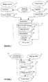
- the method can be divided into four parts: a part 1 concerning the detection of the fibers, a part 2 of calibration, a part 3 of measurement, and a part 4 of reconstruction.
- Parts 1 and 2 correspond to the diagram of the figure 2
- part 3 corresponds to the diagram of the figure 3
- part 4 corresponds to the diagram of the figure 4 .
- a calibration step is first carried out.
- the reference image 5 is an image acquired by means of a system comprising a guide consisting of a plurality of optical fibers from 10000 to 30000 for example.
- the control image 5 is obtained in such a way as to distinguish the optical fiber pattern, ie of the "egg box" type: on the profile of the image, a fiber resulting in a small mountain surrounded by pass and valley.
- the control image 5 undergoes a fiber detection operation so as to obtain a kind of mask representing the pattern of the optical fibers. This mask is the image 7 of the related components representing each fiber. At each gray level represents a unique index designating an optical fiber in the guide.
- the image 7 is then used for the calibration 2 of the image acquisition system.
- the purpose of the calibration is to determine an image of fiber-to-fiber photon injection rates. This calibration step is necessary insofar as each fiber has physical properties slightly different from the other fibers. There is therefore a certain disparity concerning the capacity of each optical fiber to convey the same photon flux.
- mirror image obtained by placing the mirror in front of the optical system of the image guide.
- This image can also be that of a homogeneous diffusing medium, a homogeneous fluorescent medium, or the own back-diffusion within the optical fiber packet.
- This image 8 can also be the same image used in 5, that is to say the control image.
- the mask 7 is used to determine the photon flux of the mirror image 8 seen by each optical fiber during step 9.
- This image 10 may correspond to parasitic reflections on the optics of the acquisition system, but also to the offset and / or the electronic noise due to the digitization chain of the system. acquisition.
- step 11 also involves the mask 7 so as to identify the zone corresponding to each fiber.
- step 12 for each optical fiber, the photon value of the mirror image 8 is subtracted by the photon flux value of the background image 10.
- step 13 it is estimated that for each optical fiber the difference obtained in step 12 corresponds to the standard injection rate for each fiber. (step 13).
- step 14 a bias correction is performed on the image of step 13.
- the image resulting from step 14 is therefore an image having for each zone corresponding to an optical fiber, a flux value of photon stallion and corrected.
- This image from step 14 will serve as a reference for a series of images acquired in real time by the acquisition system. Images acquired and processed in real time undergo the treatment shown in parts 3 and 4.
- the measurement part 3 receives an acquired image 15, typically the image of a measurement object.
- the photon flux seen by each fiber with respect to the acquired image 15 is also calculated here in step 18.
- the mask 7 is used so as to identify on the acquired image 15, the zone corresponding to each optical fiber.
- a parasitic background image 16 as before, which may be a real image, ie corresponding to the background of the acquired image 15 or an estimated image corresponding to the parasite of the acquisition system.
- This background image 16 also undergoes a step 17 by means of the mask 7 so as to determine the photon flux seen by each fiber.
- a subtraction is performed.
- the result of the subtraction is an image having for each zone corresponding to a given optical fiber, a useful photon flux.
- Step 21 is an optional step in which bias correction is performed on image 20.
- the reconstruction part 4 receives, on the one hand, the corrected image and, on the other hand, the corrected (de-biased) image 13 so as to carry out a calibration operation 22 by dividing the fluxes of the observed object ( element from step 21) by the standard flows (element from step 14). In step 22, a reconstruction is also performed so as to obtain a reconstructed image 23 without any pattern of the apparent optical fibers.
- the two correction operations are interchangeable, and they can also be performed in a loop.
- the pre-filtering operation 61 receives the control image 5 as input and generates an image of the filtered fibers of these maxima. local, and smoothed at inter-fiber areas.
- the pre-filtering involves a morphological opening operation, optionally followed by an anisotropic diffusion of scalar type, then an inversion of the image. When several images of the same fixed object are present, temporal filtering of the images can be performed. You can also interpolate to the nearest neighbor to double the size of the image vertically and horizontally.
- the image generated by the pre-filtering 61 then undergoes a water division line operation 62, making it possible to obtain an image of the connected components of the detected fibers.
- the watershed operation of conventional type, will make it possible to locate segments at the edge of the image so as to remove them from the final result.
- the characteristics of these segments obtained are then calculated (average size, standard deviation, neighborhood).
- the image resulting from the operation 62 will undergo two corrections 63 and 64 successive.
- Operation 63 is a correction of segments having an abnormally large area. To do this, we select segments that are both too large compared to an average size and have too many neighbors in relation to a normal surface of the fibers.
- These segments are re-segmented with a watershed either on the original image or on a distance map image within the detected segments (in one segment, distance between each pixel and the edge of the segment). segment). Then, the characteristics of the segments obtained are calculated (average size, standard deviation of sizes).
- the segments with an abnormally small area are corrected.
- the second correction 64 makes it possible to generate the image of the connected components which will serve as a mask for the calibration 2 and the measurement 3.
- the right part of the figure 2 relates to a calibration process 2 as represented on the figure 1 but in a simplified way. Indeed, on the figure 2 , optional operations 10 and 11 do not appear.
- the masking step 91 consists in locating on the mirror image 8 the zone or surface corresponding to each optical fiber of the guide. Image 7 of the connected components serves as a mask.
- step 92 for each optical fiber, the flux coming from the observed object is calculated. The flux is calculated using the maximum likelihood estimator determined on the specific injection profile of each optical fiber.
- step 14 a bias correction is made as will be seen in more detail on the figure 3 .
- a standard value of the photon injection rate is obtained.
- the measurement process according to the invention is distinguished. This process is done in real time.
- the zone corresponding to each optical fiber is identified by performing a masking operation 181 by means of the mask 7.
- the flux coming from the observed object is calculated at 182.
- the calculation is performed by means of the maximum likelihood estimator determined on the specific injection profile of each optical fiber.
- the same masking 171 and flux calculation operations 172 are performed on a parasitic background image 16.
- step 19 for each zone corresponding to an optical fiber, the background flux (172) is subtracted from the flux of the acquired image (182).
- the background image is not provided and this background exists, it must be subtracted, then calculates an offset and / or electronic noise of the measurement system with a quantile on the histogram of the acquired image 15 .
- bias correction can then be performed on the image resulting from the subtraction 19.
- the zones corresponding to the fibers in different blocks are spatially separated at 211.
- the value of the bias is calculated in 212 by a given operator.
- the bias values are interpolated to obtain a value for each fiber.
- a division of the value of the flow seen by each fiber by the value of the bias obtained is then carried out at 214.
- an image is generated representing the flux observed for each fiber.
- the final reconstruction step takes into account the image of the standard injection rate 24 and the observed flow image 25.
- the calibration operation is intended to compensate the injection losses by equalizing the injection rate of all the optical fibers so as to have an image of which all the fibers have been injected in the same way.
- the flux image observed at the image of the injection rate 24 is divided into 221.
- a mosaic reconstruction is then carried out by distributing the value obtained after calibration (division) in step 222 over the entire area corresponding to each fiber.
- Gaussian low-pass filtering 223 it is possible to carry out Gaussian low-pass filtering 223 for example.
Landscapes
- Physics & Mathematics (AREA)
- General Physics & Mathematics (AREA)
- Engineering & Computer Science (AREA)
- Theoretical Computer Science (AREA)
- Investigating Or Analysing Materials By Optical Means (AREA)
- Investigating, Analyzing Materials By Fluorescence Or Luminescence (AREA)
- Image Processing (AREA)
- Mechanical Coupling Of Light Guides (AREA)
Claims (30)
- Verfahren zur Verarbeitung eines aufgenommenen Bildes mittels eines Lichtleiters, der von einer Vielzahl von optischen Fasern gebildet ist, umfassend die folgenden Schritte für jede optische Faser:- auf dem aufgenommenen Bild Isolieren einer dieser optischen Faser entsprechenden Zone, wobei eine Maske angelegt wird, die dem Motiv der Vielzahl von optischen Fasern entspricht, wobei die Maske ferner einem Bild der zugehörigen Komponenten, die jede Faser darstellen, entspricht und während eines Schrittes der Erfassung der Fasern aus einem Kontrollbild erhalten wird;- lokale Verarbeitung jeder Zone auf individuelle Weise, wobei die zwei folgenden Schritte durchgeführt werden:- Berechnung des in jeder Zone des aufgenommenen Bildes erfassten Stroms,- Berechnung des in jeder Zone einer Gesamtheit von Referenzbildern einschließlich eines Hintergrundstörbildes und eines Kalibrierungsbildes, erfassten Stroms, dann- Kalibrieren des Stroms des aufgenommenen Bildes auf Basis der Ströme der Referenzbilder, dann- Rekonstruieren des aufgenommenen Bildes durch Beseitigen des Motivs auf Grund der optischen Fasern;dadurch gekennzeichnet, dass der Schritt der Erfassung der Fasern die folgenden Schritte umfasst:- Vorfiltern des Kontrollbildes,- Segmentieren pro Region,- Korrektur von Segmenten, die eine abnormal große Fläche aufweisen, und Korrektur von Segmenten, die eine abnormal kleine Fläche aufweisen,und dass die Korrektur von Segmenten die folgenden Schritte umfasst:- Auswahl der abnormal großen Segmente, die zu viele Benachbarte in Bezug zu einer normalen Fläche der Fasern haben;- Neusegmentieren mit einer Wasserscheide entweder auf dem Ursprungsbild oder auf einem Distanzkartenbild innerhalb der erfassten Segmente;- Berechnung des Angrenzungsgraphen der abnormal kleinen Segmente, bevor entschieden wird, welche Fasern obligatorisch mit jeder benachbarten verschmolzen werden müssen, und welche nur Anwärter sind.
- Verfahren nach Anspruch 1, dadurch gekennzeichnet, dass die zwei Korrekturschritte untereinander austauschbar sind.
- Verfahren nach Anspruch 1 oder 2, dadurch gekennzeichnet, dass die zwei Korrekturschritte auf iterative Weise durchgeführt werden.
- Verfahren nach einem der Ansprüche 1 bis 3, dadurch gekennzeichnet, dass der Schritt des Vorfilterns einen Schritt der morphologischen Öffnung, gefolgt von einem Schritt der Bildumkehr, umfasst.
- Verfahren nach Anspruch 4, dadurch gekennzeichnet, dass vor dem Schritt der Bildumkehr ein Schritt der anisotropen Diffusion skalaren Typs erfolgt.
- Verfahren nach einem der Ansprüche 1 bis 5, dadurch gekennzeichnet, dass das Vorfiltern ferner einen Schritt umfasst, während dessen eine nächstgelegene Interpolation durchgeführt wird, um die Größe des Bildes vertikal und horizontal zu verdoppeln.
- Verfahren nach einem der Ansprüche 1 bis 6, dadurch gekennzeichnet, dass bei Vorhandensein einer Vielzahl von aufgenommenen Bildern das Vorfiltern ferner einen Schritt der Zeitfilterung umfasst.
- Verfahren nach einem der vorhergehenden Ansprüche, dadurch gekennzeichnet, dass die lokale Verarbeitung jeder Zone eine Schräg-Korrektur des für jede Zone des aufgenommenen Bildes erfassten Photonenstroms umfasst.
- Verfahren nach Anspruch 8, dadurch gekennzeichnet, dass die Stromberechnung mit Hilfe eines Schätzers des auf einem spezifischen Injektionsprofil berechneten Wahrscheinlichkeitsmaximums erfolgt.
- Verfahren nach Anspruch 4, dadurch gekennzeichnet, dass, wenn die Maske auch an ein Bild, das einen Störhintergrund darstellt, angelegt wird, auch der für jede Zone des Hintergrundbildes erfasste Photonenstrom berechnet wird, und von jedem Stromwert jeder Zone des aufgenommenen Bildes der Stromwert jeder Zone des entsprechenden Hintergrundbildes abgezogen wird, und die Schräg-Korrektur am Resultat dieser Subtraktion durchgeführt wird.
- Verfahren nach Anspruch 10, dadurch gekennzeichnet, dass der Störhintergrund vom Hintergrund des Bildes stammt.
- Verfahren nach Anspruch 10, dadurch gekennzeichnet, dass der Störhintergrund von der Berechnung eines Versatzes der Erfassungskette stammt.
- Verfahren nach einem der Ansprüche 8 bis 12, dadurch gekennzeichnet, dass die Schräg-Korrektur darin besteht, räumlich die Fasern in verschiedene Blöcke zu trennen, den Schräg-Wert in jedem Block zu schätzen, die Schräg-Werte zu interpolieren, um einen Schräg-Wert für jede Faser zu erhalten, und für jede Zone den im vorherigen Schritt erhaltenen Stromwert durch den so erhaltenen entsprechenden Schräg-Wert zu dividieren.
- Verfahren nach einem der vorhergehenden Ansprüche, dadurch gekennzeichnet, dass die Rekonstruktion des aufgenommenen Bildes einen Schritt der Mosaikrekonstruktion einsetzt.
- Verfahren nach Anspruch 14, dadurch gekennzeichnet, dass zur Kalibrierung und für jede Zone des aufgenommenen Bildes der Wert des nach einer lokalen Verarbeitung erhaltenen Stroms durch einen Stromwert dividiert wird, der nach einem Kalibrierungsschritt erhalten wurde.
- Verfahren nach Anspruch 15, dadurch gekennzeichnet, dass der Kalibrierungsschritt darin besteht:- jede Zone eines Kalibrierungsbildes durch Anlegen der Maske entsprechend dem Motiv der Fasern auf dieses Kalibrierungsbild zu isolieren,- den für jede Zone des Kalibrierungsbildes erfassten Photonenstrom zu berechnen, und- die Schräge auf jedem so berechneten Stromwert zu korrigieren.
- Verfahren nach Anspruch 16, dadurch gekennzeichnet, dass die Stromberechnung mit Hilfe eines Schätzers des Wahrscheinlichkeitsmaximums, das auf dem spezifischen Injektionsprofil jeder Faser berechnet wurde, erfolgt.
- Verfahren nach Anspruch 17 oder 16, dadurch gekennzeichnet, dass, wenn die Maske auch auf ein einen Störhintergrund darstellendes Bild angelegt wird, auch der erfasste Photonenstrom für jede Zone des Hintergrundbildes berechnet wird, von jedem Stromwert jeder Zone des Kalibrierungsbildes der Stromwert jeder Zone des entsprechenden Hintergrundbildes abgezogen wird, und die Schräg-Korrektur am Resultat dieser Subtraktion vorgenommen wird.
- Verfahren nach Anspruch 18, dadurch gekennzeichnet, dass der Störhintergrund vom Hintergrund des Bildes stammt.
- Verfahren nach Anspruch 18, dadurch gekennzeichnet, dass der Störhintergrund von der Berechnung des Versatzes und dem Rauschen der Erfassungskette stammt.
- Verfahren nach einem der Ansprüche 14 bis 20, dadurch gekennzeichnet, dass die Mosaikrekonstruktion darin besteht, auf der gesamten Oberfläche jeder Zone des aufgenommenen Bildes den Stromwert jeder Zone, der nach dem Kalibrierungsschritt erhalten wird, zu verteilen.
- Verfahren nach Anspruch 21, dadurch gekennzeichnet, dass ein Tiefpassfiltern durchgeführt wird, um das rekonstruierte aufgenommene Bild regelmäßiger zu machen.
- Verfahren nach einem der Ansprüche 1 bis 22, dadurch gekennzeichnet, dass das Kontrollbild ein Bild ist, das durch Anordnen eines Spiegels vor dem Lichtleiter erhalten wurde.
- Verfahren nach einem der Ansprüche 1 bis 22, dadurch gekennzeichnet, dass das Kontrollbild ein Bild ist, das aus einem homogenen streuenden Medium erhalten wurde.
- Verfahren nach einem der Ansprüche 1 bis 22, dadurch gekennzeichnet, dass das Kontrollbild ein Bild ist, das aus einem homogenen fluoreszierenden Medium erhalten wurde.
- Verfahren nach einem der Ansprüche 1 bis 22, dadurch gekennzeichnet, dass das Kontrollbild ein Bild ist, das aus der Rückstreuung innerhalb des den Lichtleiter bildenden optischen Faserpakets erhalten wird.
- Verfahren nach einem der Ansprüche 1 bis 22, dadurch gekennzeichnet, dass das Kontrollbild das aufgenommene Bild ist.
- Verfahren nach einem der Ansprüche 16 bis 27, dadurch gekennzeichnet, dass das Kontrollbild und das Kalibrierungsbild identisch sind.
- Gerät zur Bildaufnahme mit Hilfe eines Lichtleiters, der von einer Vielzahl von optischen Fasern gebildet ist, das eingerichtet ist, um ein Verfahren nach einem der vorhergehenden Ansprüche für jede Faser einzusetzen, wobei das Gerät umfasst:- Mittel zum Isolieren auf dem aufgenommenen Bild einer dieser optischen Faser entsprechenden Zone, wobei eine Maske angelegt wird, die dem Motiv der Vielzahl von optischen Fasern entspricht,wobei die Maske ferner einem Bild der zugehörigen Komponenten, die jede Faser darstellen, entspricht;- Mittel, die eingerichtet sind, um das Bild der zugehörigen Komponenten während eines Schrittes der Erfassung der Fasern aus einem Kontrollbild zu erhalten;ferner umfassend:- Mittel zur lokalen Verarbeitung jeder Zone auf individuelle Weise, wobei die zwei folgenden Schritte durchgeführt werden:- Berechnung des in jeder Zone des aufgenommenen Bildes erfassten Stroms,- Berechnung des in jeder Zone einer Gesamtheit von Referenzbildern einschließlich eines Hintergrundstörbildes und eines Kalibrierungsbildes, erfassten Stroms,- Mittel zum Kalibrieren des Stroms des aufgenommenen Bildes auf Basis der Ströme der Referenzbilder, und- Mittel zum Rekonstruieren des aufgenommenen Bildes durch Beseitigen des Motivs auf Grund der optischen Fasern;dadurch gekennzeichnet, dass die Mittel zum Erhalt des Bildes der zugehörigen Komponenten umfassen:- Mittel zum Vorfiltern des Kontrollbildes,- Mittel zum Segmentieren pro Region,- Mittel zur Korrektur von Segmenten, die eine abnormal große Fläche aufweisen, und- Mittel zur Korrektur von Segmenten, die eine abnormal kleine Fläche aufweisen, umfassend:- Mittel zur Auswahl der abnormal großen Segmente, die zu viele Benachbarte in Bezug zu einer normalen Fläche der Fasern haben;- Mittel zum Neusegmentieren mit einer Wasserscheide entweder auf dem Ursprungsbild oder auf einem Distanzkartenbild innerhalb der erfassten Segmente;- Mittel zur Berechnung des Angrenzungsgraphen der abnormal kleinen Segmente,- Mittel zum Entscheiden, welche Fasern obligatorisch mit jeder benachbarten verschmolzen werden müssen, und welche nur Anwärter sind.
- Gerät nach Anspruch 29, dadurch gekennzeichnet, dass es Mittel umfasst, um die Kalibrierungsrate, die Injektionsrate in die optischen Fasern und die Einstellung einer Erfassungskette zu verändern, um ein "Eierschachtelprofil" zu gewährleisten.
Applications Claiming Priority (3)
| Application Number | Priority Date | Filing Date | Title |
|---|---|---|---|
| FR0209100 | 2002-07-18 | ||
| FR0209100A FR2842628B1 (fr) | 2002-07-18 | 2002-07-18 | "procede de traitement d'une image acquise au moyen d'un guide compose d'une pluralite de fibres optiques" |
| PCT/FR2003/002197 WO2004010377A1 (fr) | 2002-07-18 | 2003-07-11 | Procede de traitement d'une image acquise au moyen d'un guide compose d'une pluralite de fibres optiques |
Publications (2)
| Publication Number | Publication Date |
|---|---|
| EP1523731A1 EP1523731A1 (de) | 2005-04-20 |
| EP1523731B1 true EP1523731B1 (de) | 2018-06-27 |
Family
ID=29797536
Family Applications (1)
| Application Number | Title | Priority Date | Filing Date |
|---|---|---|---|
| EP03750802.5A Expired - Lifetime EP1523731B1 (de) | 2002-07-18 | 2003-07-11 | Verfahren zur verarbeitung eines bildes mittels eines lichtleiters, der aus mehreren optischen fasern besteht |
Country Status (11)
| Country | Link |
|---|---|
| US (1) | US7903848B2 (de) |
| EP (1) | EP1523731B1 (de) |
| JP (1) | JP4485947B2 (de) |
| KR (1) | KR20050021493A (de) |
| CN (1) | CN1679053B (de) |
| AU (1) | AU2003269019B2 (de) |
| CA (1) | CA2491751C (de) |
| ES (1) | ES2687644T3 (de) |
| FR (1) | FR2842628B1 (de) |
| IL (1) | IL166152A (de) |
| WO (1) | WO2004010377A1 (de) |
Families Citing this family (34)
| Publication number | Priority date | Publication date | Assignee | Title |
|---|---|---|---|---|
| FR2871358B1 (fr) | 2004-06-14 | 2007-02-09 | Mauna Kea Technologies Soc Par | Procede et systeme d'imagerie microscopique de fluorescence fibree multimarquage |
| FR2877103B1 (fr) | 2004-10-22 | 2012-02-10 | Mauna Kea Technologies | Systeme et procede d'imagerie microscopique multiphotonique fibre d'un echantillon |
| US8788021B1 (en) | 2005-01-24 | 2014-07-22 | The Board Of Trustees Of The Leland Stanford Junior Univerity | Live being optical analysis system and approach |
| US7307774B1 (en) | 2005-01-24 | 2007-12-11 | The Board Of Trustees Of The Leland Standford Junior University | Micro-optical analysis system and approach therefor |
| US8346346B1 (en) | 2005-01-24 | 2013-01-01 | The Board Of Trustees Of The Leland Stanford Junior University | Optical analysis system and approach therefor |
| KR100682978B1 (ko) * | 2005-08-19 | 2007-02-15 | 한국전자통신연구원 | 영상을 이용한 얼굴의 광학 특성 맵 추출 시스템 및 그방법 |
| DE102006011707B4 (de) * | 2006-03-14 | 2010-11-18 | Fraunhofer-Gesellschaft zur Förderung der angewandten Forschung e.V. | Verfahren und Vorrichtung zum Erzeugen einer strukturfreien fiberskopischen Aufnahme |
| FR2901029B1 (fr) * | 2006-05-12 | 2012-12-21 | Mauna Kea Technologies | Dispositif et procede d'endoscopie pour une observation simultanee de plusieurs zones d'interet. |
| CN101461273B (zh) * | 2006-06-07 | 2016-03-09 | 高通股份有限公司 | 向活动集中的网络功能体传送会话状态变化 |
| US8099156B1 (en) | 2006-09-15 | 2012-01-17 | The Board Of Trustees Of The Leland Stanford Junior University | Cochlear optical analysis system and approach therefor |
| JP4892316B2 (ja) | 2006-11-06 | 2012-03-07 | 株式会社フジクラ | マルチコアファイバ |
| US8068899B2 (en) | 2007-07-03 | 2011-11-29 | The Board Of Trustees Of The Leland Stanford Junior University | Method and system of using intrinsic-based photosensing with high-speed line scanning for characterization of biological thick tissue including muscle |
| KR100869469B1 (ko) * | 2008-04-01 | 2008-11-19 | 한국과학기술원 | 섬유 이미지의 검출 성능을 향상시키기 위한 처리 방법 |
| US8983581B2 (en) * | 2008-05-27 | 2015-03-17 | Massachusetts Institute Of Technology | System and method for large field of view, single cell analysis |
| US8270762B1 (en) * | 2008-09-27 | 2012-09-18 | Schott Corporation | Automated light-line calibration system and method of calibrating an optical fiber light line assembly |
| US8718398B2 (en) | 2008-12-29 | 2014-05-06 | Mauna Kea Technologies | Image processing method and apparatus |
| AU2010209422B2 (en) | 2009-01-30 | 2015-06-18 | Mauna Kea Technologies | Method and system for processing images acquired in real time through a medical device |
| US9155471B2 (en) | 2009-05-27 | 2015-10-13 | Lumicell, Inc'. | Methods and systems for spatially identifying abnormal cells |
| US8332332B2 (en) * | 2010-01-29 | 2012-12-11 | Xerox Corporation | Methods and apparatus for managing pre-paid printing system accounts |
| JP5570373B2 (ja) * | 2010-09-29 | 2014-08-13 | 富士フイルム株式会社 | 内視鏡システム |
| US9314304B2 (en) | 2010-12-08 | 2016-04-19 | Lumicell, Inc. | Methods and system for image guided cell ablation with microscopic resolution |
| US8969777B2 (en) | 2011-05-16 | 2015-03-03 | Mauna Kea Technologies | Method for processing images using object signals to estimate transfer functions of optical fibers |
| EP2785250A4 (de) | 2011-11-28 | 2015-07-29 | Univ Leland Stanford Junior | System und verfahren zur sarkomerdarstellung durch objektivbasierte mikroskopie |
| US9763577B2 (en) | 2013-03-14 | 2017-09-19 | Lumicell, Inc. | Imaging agent for detection of diseased cells |
| CN115919266A (zh) | 2016-03-08 | 2023-04-07 | 恩斯派克特拉健康公司 | 皮肤疾病的非侵入式检测 |
| US10959608B2 (en) | 2016-03-31 | 2021-03-30 | Tohoku University | Optical imaging device |
| WO2017174998A1 (en) | 2016-04-06 | 2017-10-12 | The University Court Of The University Of Edinburgh | Endoscopic imaging apparatus and method |
| GB201611819D0 (en) | 2016-07-07 | 2016-08-17 | Univ Court Of The Univ Of Edinburgh The | Imaging method and apparatus |
| EP3614915A4 (de) | 2017-04-28 | 2021-01-20 | Enspectra Health, Inc. | Systeme und verfahren zur bildgebung und messung von sarkomeren |
| GB201707239D0 (en) | 2017-05-05 | 2017-06-21 | Univ Edinburgh | Optical system and method |
| US11426075B1 (en) | 2017-08-23 | 2022-08-30 | Lumicell, Inc. | System and method for residual cancer cell detection |
| CN107678153B (zh) | 2017-10-16 | 2020-08-11 | 苏州微景医学科技有限公司 | 光纤束图像处理方法和装置 |
| CN107622491B (zh) * | 2017-10-16 | 2022-03-11 | 苏州微景医学科技有限公司 | 光纤束图像分析方法和装置 |
| CN113473900B (zh) | 2018-11-13 | 2024-09-24 | 恩斯派克特拉健康公司 | 用于生成深度剖面的方法和系统 |
Citations (2)
| Publication number | Priority date | Publication date | Assignee | Title |
|---|---|---|---|---|
| WO1997041479A1 (en) * | 1996-04-26 | 1997-11-06 | Alpha Innotech Corporation | Anti-vibration stabilizer for a portable emission microscope |
| WO2001067370A2 (en) * | 2000-03-06 | 2001-09-13 | Gene Logic, Inc. | Virtual gel profiling system |
Family Cites Families (11)
| Publication number | Priority date | Publication date | Assignee | Title |
|---|---|---|---|---|
| JPS5810032A (ja) * | 1981-07-09 | 1983-01-20 | オリンパス光学工業株式会社 | 内視鏡 |
| JPS63155115A (ja) * | 1986-12-19 | 1988-06-28 | Olympus Optical Co Ltd | 立体観察電子内視鏡 |
| JPH04138127A (ja) * | 1990-09-28 | 1992-05-12 | Olympus Optical Co Ltd | 内視鏡網目画像軽減装置 |
| JP3078085B2 (ja) * | 1991-03-26 | 2000-08-21 | オリンパス光学工業株式会社 | 画像処理装置および画像処理方法 |
| JPH08191439A (ja) | 1995-01-10 | 1996-07-23 | Fukuda Denshi Co Ltd | 内視画像補正方法及び装置 |
| US6080104A (en) * | 1995-05-16 | 2000-06-27 | Asahi Kogaku Kogyo Kabushiki Kaisha | Electronic endoscope system |
| WO1997007627A2 (de) * | 1995-08-17 | 1997-02-27 | Karl Storz Gmbh & Co. | Endoskopie-videosystem |
| JP4008184B2 (ja) * | 1996-03-06 | 2007-11-14 | 富士フイルム株式会社 | 蛍光検出装置 |
| WO1997042600A1 (fr) * | 1996-05-02 | 1997-11-13 | Andromis S.A. | Procede de traitement d'images obtenues par fibres multicoeurs ou multifibres, en particulier d'images endoscopiques |
| JP3176574B2 (ja) * | 1997-10-15 | 2001-06-18 | 住友電気工業株式会社 | 光ファイバ観察装置および光ファイバ融着接続装置 |
| US6885801B1 (en) * | 2001-12-06 | 2005-04-26 | Clear Image Technology Llc | Enhancement of fiber based images |
-
2002
- 2002-07-18 FR FR0209100A patent/FR2842628B1/fr not_active Expired - Lifetime
-
2003
- 2003-07-11 KR KR10-2005-7000839A patent/KR20050021493A/ko not_active Withdrawn
- 2003-07-11 WO PCT/FR2003/002197 patent/WO2004010377A1/fr not_active Ceased
- 2003-07-11 EP EP03750802.5A patent/EP1523731B1/de not_active Expired - Lifetime
- 2003-07-11 CN CN038210312A patent/CN1679053B/zh not_active Expired - Lifetime
- 2003-07-11 US US10/520,917 patent/US7903848B2/en active Active
- 2003-07-11 AU AU2003269019A patent/AU2003269019B2/en not_active Expired
- 2003-07-11 CA CA2491751A patent/CA2491751C/fr not_active Expired - Lifetime
- 2003-07-11 ES ES03750802.5T patent/ES2687644T3/es not_active Expired - Lifetime
- 2003-07-11 JP JP2004522235A patent/JP4485947B2/ja not_active Expired - Lifetime
-
2005
- 2005-01-05 IL IL166152A patent/IL166152A/en unknown
Patent Citations (2)
| Publication number | Priority date | Publication date | Assignee | Title |
|---|---|---|---|---|
| WO1997041479A1 (en) * | 1996-04-26 | 1997-11-06 | Alpha Innotech Corporation | Anti-vibration stabilizer for a portable emission microscope |
| WO2001067370A2 (en) * | 2000-03-06 | 2001-09-13 | Gene Logic, Inc. | Virtual gel profiling system |
Also Published As
| Publication number | Publication date |
|---|---|
| ES2687644T3 (es) | 2018-10-26 |
| EP1523731A1 (de) | 2005-04-20 |
| FR2842628B1 (fr) | 2004-09-24 |
| CA2491751C (fr) | 2015-10-13 |
| IL166152A0 (en) | 2006-01-15 |
| AU2003269019B2 (en) | 2009-09-10 |
| WO2004010377A1 (fr) | 2004-01-29 |
| AU2003269019A1 (en) | 2004-02-09 |
| JP4485947B2 (ja) | 2010-06-23 |
| CA2491751A1 (fr) | 2004-01-29 |
| CN1679053B (zh) | 2013-07-17 |
| KR20050021493A (ko) | 2005-03-07 |
| FR2842628A1 (fr) | 2004-01-23 |
| CN1679053A (zh) | 2005-10-05 |
| JP2005532884A (ja) | 2005-11-04 |
| US7903848B2 (en) | 2011-03-08 |
| IL166152A (en) | 2010-12-30 |
| US20050207668A1 (en) | 2005-09-22 |
Similar Documents
| Publication | Publication Date | Title |
|---|---|---|
| EP1523731B1 (de) | Verfahren zur verarbeitung eines bildes mittels eines lichtleiters, der aus mehreren optischen fasern besteht | |
| EP2174289B1 (de) | Verfahren zur verarbeitung eines digitalen objekts und entsprechendes system | |
| CA2834883C (fr) | Procede pour commander une action, notamment une modification de nettete, a partir d'une image numerique en couleurs | |
| EP2304686B1 (de) | Verfahren und vorrichtung zur füllung von verdunkelungsbereichen in einer auf basis mindestens zweier bilder entwickelten tiefen- oder disparitätskarte | |
| EP0720125B1 (de) | Bilderzeugungsgerät und Verfahren zur Verbesserung geometrischer optischer Bildverzerrungen | |
| WO1991005443A1 (fr) | Procede et dispositif d'incrustation d'images video couleur auto-adaptatif | |
| EP0945830B1 (de) | Bildverarbeitungsverfahren mit multidimensionalen Bildsegmentationsstufen und medizinische Vorrichtung die diese verwendet | |
| EP0822515A1 (de) | Verfahren zur automatischen Segmentierung von numerischen Bildern und Vorrichtung zur Ausführung dieses Verfahrens | |
| WO1997042600A1 (fr) | Procede de traitement d'images obtenues par fibres multicoeurs ou multifibres, en particulier d'images endoscopiques | |
| EP3114831B1 (de) | Optimierte videorauschunterdrückung für heterogenes multisensorsystem | |
| FR2948521A1 (fr) | Procede d'estimation d'un defaut d'un systeme de capture d'images et systemes associes | |
| EP4020978B1 (de) | Verfahren zur eichung einer matrix von photodetektoren, entsprechende eichungsvorrichtung und entsprechendes bildgebungssystem | |
| FR2701766A1 (fr) | Procédé d'acquisition et de traitement de l'image d'un article plan, du type étoffe de tissu, en vue de la détection de défauts de fabrication. | |
| FR2884948A1 (fr) | Procede et dispositif de reduction du bruit dans une sequence d'images fluoroscopiques | |
| EP1080448B1 (de) | Verfahren zur vereinfachung eines bildes zum benutzen in einem bildsegmentations- und -codierungsverfahren | |
| Balasubramanian et al. | A ringing metric to evaluate the quality of images restored using iterative deconvolution algorithms | |
| WO2013045853A1 (fr) | Méthode et dispositif de filtrage d'une carte de disparité | |
| FR2910673A1 (fr) | Procede de traitement d'image et dispositif implementant ledit procede | |
| WO2023001931A1 (fr) | Procédé d'acquisition d'image en deux dimensions d'un échantillon biologique à balayage ciblé | |
| FR2931935A1 (fr) | Procede de traitement d'une serie d'images en coupe d'un objet pour mesurer le volume de cet objet | |
| FR2696029A1 (fr) | Processeur adaptatif de régénération d'image. | |
| FR2730577A1 (fr) | Procede et dispositif de correction des defauts de lignage d'une image obtenue par balayage d'un champ par un reseau de photodetecteurs |
Legal Events
| Date | Code | Title | Description |
|---|---|---|---|
| PUAI | Public reference made under article 153(3) epc to a published international application that has entered the european phase |
Free format text: ORIGINAL CODE: 0009012 |
|
| 17P | Request for examination filed |
Effective date: 20050215 |
|
| AK | Designated contracting states |
Kind code of ref document: A1 Designated state(s): AT BE BG CH CY CZ DE DK EE ES FI FR GB GR HU IE IT LI LU MC NL PT RO SE SI SK TR |
|
| AX | Request for extension of the european patent |
Extension state: AL LT LV MK |
|
| RIN1 | Information on inventor provided before grant (corrected) |
Inventor name: BERIER, FREDERIC Inventor name: LE GOUALHER, GEORGES Inventor name: PERCHANT, AYMERIC |
|
| RIN1 | Information on inventor provided before grant (corrected) |
Inventor name: PERCHANT, AYMERIC Inventor name: LE GOUALHER, GEORGES Inventor name: BERIER, FREDERIC |
|
| RIN1 | Information on inventor provided before grant (corrected) |
Inventor name: PERCHANT, AYMERIC Inventor name: LE GOUALHER, GEORGES Inventor name: BERIER, FREDERIC |
|
| 17Q | First examination report despatched |
Effective date: 20091218 |
|
| STAA | Information on the status of an ep patent application or granted ep patent |
Free format text: STATUS: EXAMINATION IS IN PROGRESS |
|
| GRAP | Despatch of communication of intention to grant a patent |
Free format text: ORIGINAL CODE: EPIDOSNIGR1 |
|
| STAA | Information on the status of an ep patent application or granted ep patent |
Free format text: STATUS: GRANT OF PATENT IS INTENDED |
|
| INTG | Intention to grant announced |
Effective date: 20180122 |
|
| GRAS | Grant fee paid |
Free format text: ORIGINAL CODE: EPIDOSNIGR3 |
|
| GRAA | (expected) grant |
Free format text: ORIGINAL CODE: 0009210 |
|
| STAA | Information on the status of an ep patent application or granted ep patent |
Free format text: STATUS: THE PATENT HAS BEEN GRANTED |
|
| REG | Reference to a national code |
Ref country code: DE Ref legal event code: R081 Ref document number: 60351282 Country of ref document: DE Owner name: MAUNA KEA TECHNOLOGIES, FR Free format text: FORMER OWNER: MAUNA KEA TECHNOLOGIES, PARIS, FR |
|
| AK | Designated contracting states |
Kind code of ref document: B1 Designated state(s): AT BE BG CH CY CZ DE DK EE ES FI FR GB GR HU IE IT LI LU MC NL PT RO SE SI SK TR |
|
| AX | Request for extension of the european patent |
Extension state: AL LT LV MK |
|
| REG | Reference to a national code |
Ref country code: GB Ref legal event code: FG4D Free format text: NOT ENGLISH |
|
| REG | Reference to a national code |
Ref country code: AT Ref legal event code: REF Ref document number: 1012965 Country of ref document: AT Kind code of ref document: T Effective date: 20180715 |
|
| REG | Reference to a national code |
Ref country code: FR Ref legal event code: PLFP Year of fee payment: 16 |
|
| REG | Reference to a national code |
Ref country code: IE Ref legal event code: FG4D Free format text: LANGUAGE OF EP DOCUMENT: FRENCH |
|
| REG | Reference to a national code |
Ref country code: DE Ref legal event code: R096 Ref document number: 60351282 Country of ref document: DE |
|
| REG | Reference to a national code |
Ref country code: ES Ref legal event code: FG2A Ref document number: 2687644 Country of ref document: ES Kind code of ref document: T3 Effective date: 20181026 |
|
| PG25 | Lapsed in a contracting state [announced via postgrant information from national office to epo] |
Ref country code: BG Free format text: LAPSE BECAUSE OF FAILURE TO SUBMIT A TRANSLATION OF THE DESCRIPTION OR TO PAY THE FEE WITHIN THE PRESCRIBED TIME-LIMIT Effective date: 20180927 Ref country code: FI Free format text: LAPSE BECAUSE OF FAILURE TO SUBMIT A TRANSLATION OF THE DESCRIPTION OR TO PAY THE FEE WITHIN THE PRESCRIBED TIME-LIMIT Effective date: 20180627 Ref country code: SE Free format text: LAPSE BECAUSE OF FAILURE TO SUBMIT A TRANSLATION OF THE DESCRIPTION OR TO PAY THE FEE WITHIN THE PRESCRIBED TIME-LIMIT Effective date: 20180627 |
|
| REG | Reference to a national code |
Ref country code: NL Ref legal event code: MP Effective date: 20180627 |
|
| REG | Reference to a national code |
Ref country code: LT Ref legal event code: MG9D |
|
| PG25 | Lapsed in a contracting state [announced via postgrant information from national office to epo] |
Ref country code: GR Free format text: LAPSE BECAUSE OF FAILURE TO SUBMIT A TRANSLATION OF THE DESCRIPTION OR TO PAY THE FEE WITHIN THE PRESCRIBED TIME-LIMIT Effective date: 20180928 |
|
| REG | Reference to a national code |
Ref country code: AT Ref legal event code: MK05 Ref document number: 1012965 Country of ref document: AT Kind code of ref document: T Effective date: 20180627 |
|
| PG25 | Lapsed in a contracting state [announced via postgrant information from national office to epo] |
Ref country code: NL Free format text: LAPSE BECAUSE OF FAILURE TO SUBMIT A TRANSLATION OF THE DESCRIPTION OR TO PAY THE FEE WITHIN THE PRESCRIBED TIME-LIMIT Effective date: 20180627 |
|
| PG25 | Lapsed in a contracting state [announced via postgrant information from national office to epo] |
Ref country code: EE Free format text: LAPSE BECAUSE OF FAILURE TO SUBMIT A TRANSLATION OF THE DESCRIPTION OR TO PAY THE FEE WITHIN THE PRESCRIBED TIME-LIMIT Effective date: 20180627 Ref country code: AT Free format text: LAPSE BECAUSE OF FAILURE TO SUBMIT A TRANSLATION OF THE DESCRIPTION OR TO PAY THE FEE WITHIN THE PRESCRIBED TIME-LIMIT Effective date: 20180627 Ref country code: RO Free format text: LAPSE BECAUSE OF FAILURE TO SUBMIT A TRANSLATION OF THE DESCRIPTION OR TO PAY THE FEE WITHIN THE PRESCRIBED TIME-LIMIT Effective date: 20180627 Ref country code: SK Free format text: LAPSE BECAUSE OF FAILURE TO SUBMIT A TRANSLATION OF THE DESCRIPTION OR TO PAY THE FEE WITHIN THE PRESCRIBED TIME-LIMIT Effective date: 20180627 Ref country code: CZ Free format text: LAPSE BECAUSE OF FAILURE TO SUBMIT A TRANSLATION OF THE DESCRIPTION OR TO PAY THE FEE WITHIN THE PRESCRIBED TIME-LIMIT Effective date: 20180627 |
|
| REG | Reference to a national code |
Ref country code: CH Ref legal event code: PL |
|
| REG | Reference to a national code |
Ref country code: DE Ref legal event code: R097 Ref document number: 60351282 Country of ref document: DE |
|
| PG25 | Lapsed in a contracting state [announced via postgrant information from national office to epo] |
Ref country code: LU Free format text: LAPSE BECAUSE OF NON-PAYMENT OF DUE FEES Effective date: 20180711 Ref country code: MC Free format text: LAPSE BECAUSE OF FAILURE TO SUBMIT A TRANSLATION OF THE DESCRIPTION OR TO PAY THE FEE WITHIN THE PRESCRIBED TIME-LIMIT Effective date: 20180627 |
|
| REG | Reference to a national code |
Ref country code: BE Ref legal event code: MM Effective date: 20180731 |
|
| REG | Reference to a national code |
Ref country code: IE Ref legal event code: MM4A |
|
| PG25 | Lapsed in a contracting state [announced via postgrant information from national office to epo] |
Ref country code: CH Free format text: LAPSE BECAUSE OF NON-PAYMENT OF DUE FEES Effective date: 20180731 Ref country code: LI Free format text: LAPSE BECAUSE OF NON-PAYMENT OF DUE FEES Effective date: 20180731 Ref country code: IE Free format text: LAPSE BECAUSE OF NON-PAYMENT OF DUE FEES Effective date: 20180711 |
|
| PLBE | No opposition filed within time limit |
Free format text: ORIGINAL CODE: 0009261 |
|
| STAA | Information on the status of an ep patent application or granted ep patent |
Free format text: STATUS: NO OPPOSITION FILED WITHIN TIME LIMIT |
|
| PG25 | Lapsed in a contracting state [announced via postgrant information from national office to epo] |
Ref country code: BE Free format text: LAPSE BECAUSE OF NON-PAYMENT OF DUE FEES Effective date: 20180731 Ref country code: DK Free format text: LAPSE BECAUSE OF FAILURE TO SUBMIT A TRANSLATION OF THE DESCRIPTION OR TO PAY THE FEE WITHIN THE PRESCRIBED TIME-LIMIT Effective date: 20180627 |
|
| 26N | No opposition filed |
Effective date: 20190328 |
|
| PG25 | Lapsed in a contracting state [announced via postgrant information from national office to epo] |
Ref country code: SI Free format text: LAPSE BECAUSE OF FAILURE TO SUBMIT A TRANSLATION OF THE DESCRIPTION OR TO PAY THE FEE WITHIN THE PRESCRIBED TIME-LIMIT Effective date: 20180627 |
|
| PG25 | Lapsed in a contracting state [announced via postgrant information from national office to epo] |
Ref country code: TR Free format text: LAPSE BECAUSE OF FAILURE TO SUBMIT A TRANSLATION OF THE DESCRIPTION OR TO PAY THE FEE WITHIN THE PRESCRIBED TIME-LIMIT Effective date: 20180627 |
|
| PG25 | Lapsed in a contracting state [announced via postgrant information from national office to epo] |
Ref country code: HU Free format text: LAPSE BECAUSE OF FAILURE TO SUBMIT A TRANSLATION OF THE DESCRIPTION OR TO PAY THE FEE WITHIN THE PRESCRIBED TIME-LIMIT; INVALID AB INITIO Effective date: 20030711 Ref country code: PT Free format text: LAPSE BECAUSE OF FAILURE TO SUBMIT A TRANSLATION OF THE DESCRIPTION OR TO PAY THE FEE WITHIN THE PRESCRIBED TIME-LIMIT Effective date: 20180627 |
|
| PG25 | Lapsed in a contracting state [announced via postgrant information from national office to epo] |
Ref country code: CY Free format text: LAPSE BECAUSE OF FAILURE TO SUBMIT A TRANSLATION OF THE DESCRIPTION OR TO PAY THE FEE WITHIN THE PRESCRIBED TIME-LIMIT Effective date: 20180627 |
|
| PGFP | Annual fee paid to national office [announced via postgrant information from national office to epo] |
Ref country code: IT Payment date: 20220726 Year of fee payment: 20 Ref country code: GB Payment date: 20220720 Year of fee payment: 20 Ref country code: ES Payment date: 20220921 Year of fee payment: 20 Ref country code: DE Payment date: 20220720 Year of fee payment: 20 |
|
| PGFP | Annual fee paid to national office [announced via postgrant information from national office to epo] |
Ref country code: FR Payment date: 20220726 Year of fee payment: 20 |
|
| REG | Reference to a national code |
Ref country code: DE Ref legal event code: R071 Ref document number: 60351282 Country of ref document: DE |
|
| REG | Reference to a national code |
Ref country code: ES Ref legal event code: FD2A Effective date: 20230728 |
|
| REG | Reference to a national code |
Ref country code: GB Ref legal event code: PE20 Expiry date: 20230710 |
|
| PG25 | Lapsed in a contracting state [announced via postgrant information from national office to epo] |
Ref country code: GB Free format text: LAPSE BECAUSE OF EXPIRATION OF PROTECTION Effective date: 20230710 Ref country code: ES Free format text: LAPSE BECAUSE OF EXPIRATION OF PROTECTION Effective date: 20230712 |