EP1523644B1 - Device for controlling the temperature of objects - Google Patents
Device for controlling the temperature of objects Download PDFInfo
- Publication number
- EP1523644B1 EP1523644B1 EP03740268A EP03740268A EP1523644B1 EP 1523644 B1 EP1523644 B1 EP 1523644B1 EP 03740268 A EP03740268 A EP 03740268A EP 03740268 A EP03740268 A EP 03740268A EP 1523644 B1 EP1523644 B1 EP 1523644B1
- Authority
- EP
- European Patent Office
- Prior art keywords
- air
- thermally
- facilities
- dryer
- objects
- Prior art date
- Legal status (The legal status is an assumption and is not a legal conclusion. Google has not performed a legal analysis and makes no representation as to the accuracy of the status listed.)
- Expired - Lifetime
Links
Images

Classifications
-
- F—MECHANICAL ENGINEERING; LIGHTING; HEATING; WEAPONS; BLASTING
- F26—DRYING
- F26B—DRYING SOLID MATERIALS OR OBJECTS BY REMOVING LIQUID THEREFROM
- F26B21/00—Arrangements for supplying or controlling air or other gases for drying solid materials or objects
- F26B21/20—Circulating air or gases in closed cycles, e.g. wholly within the drying enclosure
- F26B21/25—Circulating air or gases in closed cycles, e.g. wholly within the drying enclosure partly outside the drying enclosure
-
- F—MECHANICAL ENGINEERING; LIGHTING; HEATING; WEAPONS; BLASTING
- F26—DRYING
- F26B—DRYING SOLID MATERIALS OR OBJECTS BY REMOVING LIQUID THEREFROM
- F26B15/00—Machines or apparatus for drying objects with progressive movement; Machines or apparatus with progressive movement for drying batches of material in compact form
- F26B15/10—Machines or apparatus for drying objects with progressive movement; Machines or apparatus with progressive movement for drying batches of material in compact form with movement in a path composed of one or more straight lines, e.g. compound, the movement being in alternate horizontal and vertical directions
- F26B15/12—Machines or apparatus for drying objects with progressive movement; Machines or apparatus with progressive movement for drying batches of material in compact form with movement in a path composed of one or more straight lines, e.g. compound, the movement being in alternate horizontal and vertical directions the lines being all horizontal or slightly inclined
-
- F—MECHANICAL ENGINEERING; LIGHTING; HEATING; WEAPONS; BLASTING
- F26—DRYING
- F26B—DRYING SOLID MATERIALS OR OBJECTS BY REMOVING LIQUID THEREFROM
- F26B2210/00—Drying processes and machines for solid objects characterised by the specific requirements of the drying goods
- F26B2210/12—Vehicle bodies, e.g. after being painted
Definitions
- the invention relates to a device for tempering objects according to the preamble of patent claim 1.
- tempering is used here as a generic term for all types, as the temperature of the air to be applied to the objects is set to a certain value.
- Temperaturerieren can thus mean, for example, “heating”, which is particularly important in the design of the device as a dryer. However, “tempering” can also be “cooling” if the objects are to be brought to a lower temperature.
- a device of the type mentioned is from the US 2002/0 056 710 A1 known.
- printed circuit boards are guided in parallel juxtaposed and vertically stacked conveyor belts through a plurality of heating or cooling zones, which are each associated with corresponding heating or cooling devices.
- the achievable throughput of printed circuit boards is increased.
- the use of inert gas is mentioned in this document, but not the way in which this is performed.
- the partially juxtaposed conveyor belts of the space requirement of this device due to the dimensions of tempered objects is rather low.
- Object of the present invention is to provide a device of the type mentioned in such a way that it meets the structural conditions at the place where it is to be installed, and can be easily adapted to different capacities.
- the air path on which the tempered air flows to a first tempering device passes through a second tempering device.
- air ducts can be saved since a part of the air path to the first temperature control device is provided by the second temperature control device.
- a device is also provided with which the transition of tempered air from the second tempering device into the first tempering device can be interrupted if necessary.
- the device can thus be run with two different capacities: With a larger capacity, in which both tempering are in operation, and with a smaller capacity, which corresponds to the capacity of that, second tempering, through which the airway leads first.
- an adaptation to the respective Temperier pressure be made; in contrast to devices in which the air connection between the at least two tempering permanently, so both temperature control must always be operated simultaneously and in parallel.
- connection in question can be interrupted by hand through a corresponding part, which is inserted into the airway.
- a grate through which the air flows from the second temperature control device into the first temperature control device, can be replaced manually with a closed metal plate.
- the device for interrupting the airway is a controllable flap or a closable blind.
- the at least two tempering devices at least partially divide the air path, on which the air is discharged from the utility rooms, a reduction of the apparatus expenditure, in particular of the required air ducts, is possible again.
- the device can be designed as a dryer; for tempering the air, it then has at least one heating unit.
- the dryer according to the invention has as many heating units as drying devices. If individual drying devices are taken out of operation within the entire dryer then correspondingly many heating units can also be put out of action, which is associated with considerable energy savings. In addition, it is possible to drive in the different drying equipment within the same dryer with different air temperatures.
- the device according to the invention can also be designed as a cooler.
- at least one fan may be provided, which sucks fresh air and brings as tempered air in the Nutzhoffmme the cooling devices.
- At least one cooling aggregate can additionally be provided, which cools the air introduced into the working spaces of the cooling devices.
- the items to be tempered may in particular also be vehicle bodies.
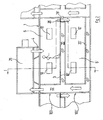
- a circulating air heating unit 25 is arranged above the housing 1.
- the air heated by this occurs via lateral connecting channels 4, 5 in the upper "floor” of the housing 1 and there in each of the lateral outer wall adjacent pressure chamber 6, 7 a first, provided with the reference numeral 100 drying device.
- the pressure chambers 6, 7 are bounded inwardly by a vertical partition wall 8, 9, in which there are provided with filters 10, 11 openings. For maintenance of the filters 10, 11 or cleaning the pressure chambers 6, 7, the latter can be committed, as indicated schematically in the left pressure chamber 6.
- an air distribution space 15 or 16 is formed in each case.
- the heated air passes from the air distribution chambers 15, 16 via nozzles 17, 18 in the side walls 12, 13 in a tunnel-like working space 14 and acts there, as indicated by the arrows, an object to be dried, in the example shown, a freshly painted vehicle body 19th
- connection channels 22, 23 are in FIG. 1 not directly visible but covered by the pressure chambers 6 and 7 and indicated by the dashed, upward arrows only symbolically.
- the objects 19 to be dried are moved by the dryer unit 100 accommodated in the upper "floor" of the housing 1 by means of a conveyor 24 perpendicular to the drawing plane of FIG FIG. 1 transported through.
- An almost completely identical drying device 100 ' is located below the first dryer device 100 in the lower "floor" of the housing 1. Also, this dryer device 100' comprises a work space 14 'with side walls 12', 13 ', which air distribution spaces 15' 16 'limit inward , The air distribution chambers 15 '16' are connected to the work space 14 'via nozzles 17', 18 '. Outside the air distribution spaces 15 ', 16' are, separated from them by vertical partitions 8 ', 9', pressure chambers 6 ', 7', from which hot air through filter 10 ', 11' in the intermediate walls 8 ', 9' in the air distribution spaces 15 ', 16' can get. The heated air is sucked out of the usable space 14 'via bottom channels 20', 21 'and from there into the same vertical connection channels 22, which have already been described above for the drying device 100 arranged in the upper "floor".
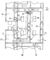
- FIG. 2 makes clear that what has been described above is only one segment of a complete dryer.
- FIG. 2 Close to the left and right of the illustrated segment more, essentially identically designed segments. These differ from the middle segment essentially at most in the temperature of the air introduced into the respective utility rooms.
- the conveyor systems 24, 24 'pass all of these segments from an inlet lock located at one end of the dryer housing to an outlet lock located at the other end of the dryer housing; both locks are in FIG. 2 not shown and basically have a known construction, in particular that of an A-lock.
- 100 'located in the lower and upper "floor" of the housing 1 are preferably operated simultaneously.
- the gratings 26, 27 are closed by eg manually insertable sheets.
- the air capacity of the heating unit 25 is adapted in this case to the reduced demand, for example with a frequency converter.
- FIG. 1 was in the description of the first embodiment as a section along the line II of FIG. 2 to understand; she will now be in the description of the second embodiment as a section along line II of FIG. 3 used.
- FIG. 3 is similar to the one of FIG. 2 very strong; corresponding parts are therefore in FIG. 3 with the same reference numerals as in Figures 1 and 2 provided.
- Drying device 100 'can be switched off are compared to the embodiment of FIG. 2 the following changes have been made:
- FIGS. 1 and 3 illustrated embodiment is operated as follows:
- both recirculating air heaters 25 and 25 ' are used.
- both circulating air heating units 25, 25 'blow air heated into the lateral pressure chambers 6, 7 of the upper dryer device 100 which partially circulates in the already described manner over the working space 14 of the upper dryer device 100, via the upper floor channels 20 , 21 aspirated and the vertical connection channels 22, 23 are fed back to the first circulating air heating unit 25.
- the drying device 100 'located in the lower floor can be shut down as follows: vertically extending connecting channels 28 ', 29' up to the second circulating air heating unit 25 'out.
- the drying device 100 'located in the lower floor can be shut down as follows: FIG. 3 right circulating air heating unit 25 'is taken out of service; the flap 30 is closed as well as the flap 31 '. This in FIG. 3 left circulating air heating unit 25, however, remains in function; the heated air from this is circulated exclusively on the upper usable space 14 and dries the articles 19 passed therethrough.
- FIGS. 1 to 3 It was assumed that the device shown is a dryer in each case. However, the same construction can also be used for coolers; the only change that has to be made for this purpose is that the respective circulating air heating units 25, 25 'are replaced by cooling units.
- a designed as a cooler device may be connected to an acting as a dryer device, between the two devices only a short airlock or similar device must be provided, which separates the warmer atmosphere of the dryer from the cool atmosphere of the radiator.
- Possibly. can also be dispensed with a refrigeration unit.
- fresh air can be injected into the pressure chambers 6, 7, 6 ', 7' of the cooler, which impinges on the objects 19, 19 'to be cooled in the utility rooms 14, 14'.
- the thus heated air is sucked through the bottom channels 20, 21, 20 ', 21' and guided over the now serving as exhaust ducts vertical connecting lines 22, 23, 22 ', 23' to a fan that promotes the air either in the atmosphere or but supplies all or part of it to a subsequent zone or other facilities.
- the fresh air is very cold, it may also be necessary to achieve a desired air temperature in the individual case, to provide a heater in the radiator, which warms the fresh air accordingly.
Landscapes
- Engineering & Computer Science (AREA)
- Mechanical Engineering (AREA)
- General Engineering & Computer Science (AREA)
- Drying Of Solid Materials (AREA)
Description
Die Erfindung betrifft eine Vorrichtung zum Temperieren von Gegenständen nach dem Oberbegriff des Patentanspruchs 1.The invention relates to a device for tempering objects according to the preamble of patent claim 1.
Der Begriff des "Temperierens" wird vorliegend als Oberbegriff für alle Arten benutzt, wie die Temperatur der Luft, mit dem Gegenstände beaufschlagt werden sollen, auf einen bestimmten Wert eingestellt wird. "Temperieren" kann also beispielsweise "Erhitzen" bedeuten, was insbesondere bei der Ausgestaltung der Vorrichtung als Trockner von Bedeutung ist. "Temperieren" kann aber auch "Kühlen" sein, wenn die Gegenstände auf eine niedrigere Temperatur gebracht werden sollen.The term "tempering" is used here as a generic term for all types, as the temperature of the air to be applied to the objects is set to a certain value. "Temperieren" can thus mean, for example, "heating", which is particularly important in the design of the device as a dryer. However, "tempering" can also be "cooling" if the objects are to be brought to a lower temperature.
Eine Vorrichtung der eingangs genannten Art ist aus der
Vorrichtungen ähnlich denen der eingangs genannten Art sind in der Automobilindustrie vom Markt her bekannt, wo lackierte Fahrzeugkarosserien oder Karosseriebauteile getrocknet oder gekühlt werden sollen. Zur Steigerung der Trocknungs- bzw. Kühlkapazität werden häufig mehrere parallel angeordnete Temperiereinrichtungen, also Trockner- oder Kühleinrichtungen, eingesetzt, die entweder jeweils als "Einzelröhren" durch gesonderte Gehäuse oder, nebeneinander liegend, durch ein und dasselbe Gehäuse geführt werden. Der Platzbedarf dieser bekannten Vorrichtungen ist jedoch verhältnismäßig groß.Devices similar to those of the type mentioned are known in the automotive industry from the market, where painted vehicle bodies or body parts to be dried or cooled. To increase the drying or cooling capacity, a plurality of tempering devices arranged in parallel, that is to say drying or cooling devices, are frequently used, which are guided either as "individual tubes" by separate housings or, lying side by side, through one and the same housing. The space requirement of these known devices, however, is relatively large.
Aufgabe der vorliegenden Erfindung ist es, eine Vorrichtung der eingangs genannten Art so auszugestalten, dass sie den baulichen Gegebenheiten an dem Ort, wo sie aufgestellt werden soll, gerecht wird und auf einfache Weise an unterschiedliche Kapazitäten angepasst werden kann.Object of the present invention is to provide a device of the type mentioned in such a way that it meets the structural conditions at the place where it is to be installed, and can be easily adapted to different capacities.
Diese Aufgabe wird erfindungsgemäß durch eine Vorrichtung mit den im Patentanspruch 1 genannten Merkmalen gelöst.This object is achieved by a device having the features mentioned in claim 1.
Mit der vorliegenden Erfindung wird von der Erkenntnis Gebrauch gemacht, dass das "kostbare Gut" am Aufstellungsort der Vorrichtung weniger die Bauhöhe als die Grundfläche ist. Dadurch, dass die Temperiereinrichtungen nicht neben, sondern übereinander in dem Gehäuse angeordnet werden, wird bei gegebenem Durchsatz Grundfläche eingespart. Durch die Anordnung der mehreren Temperiereinrichtungen übereinander kann zusätzlich das Wirkprinzip der sog. "A-Schleusen" genutzt oder verstärkt werden, die bereits bei bekannten Trocknern eingesetzt wird.With the present invention, use is made of the knowledge that the "precious good" at the site of the device less the height than the base area. Because the temperature control devices are not arranged next to each other, but one above the other in the housing, the base area is saved for a given throughput. By arranging the plurality of tempering devices one above the other, the working principle of the so-called "A-locks" can be used or reinforced, which is already used in known dryers.
Erfindungsgemäß führt der Luftweg, auf dem die temperierte Luft zu einer ersten Temperiereinrichtung strömt, durch eine zweite Temperiereinrichtung. Auf diese Weise können Luftkanäle eingespart werden, da ein Teil des Luftweges zu der ersten Temperiereinrichtung von der zweiten Temperiereinrichtung bereitgestellt wird.According to the invention, the air path on which the tempered air flows to a first tempering device, passes through a second tempering device. In this way, air ducts can be saved since a part of the air path to the first temperature control device is provided by the second temperature control device.
Erfindungsgemäß ist außerdem eine Einrichtung vorgesehen, mit welcher der Übergang temperierter Luft aus der zweiten Temperiereinrichtung in die erste Temperiereinrichtung bei Bedarf unterbrochen werden kann. Dadurch kann die Vorrichtung also mit zwei unterschiedlichen Kapazitäten gefahren werden: Mit einer größeren Kapazität, bei welcher beide Temperiereinrichtungen im Betrieb sind, und mit einer kleineren Kapazität, die der Kapazität derjenigen, zweiten Temperiereinrichtung entspricht, durch welche der Luftweg zuerst führt. Somit kann eine Anpassung an den jeweiligen Temperierbedarf vorgenommen werden; im Gegensatz zu Vorrichtungen, bei welchen die Luftverbindung zwischen den mindestens zwei Temperiereinrichtungen permanent besteht, so dass beide Temperiereinrichtungen stets gleichzeitig und parallel betrieben werden müssen.According to the invention, a device is also provided with which the transition of tempered air from the second tempering device into the first tempering device can be interrupted if necessary. Thus, the device can thus be run with two different capacities: With a larger capacity, in which both tempering are in operation, and with a smaller capacity, which corresponds to the capacity of that, second tempering, through which the airway leads first. Thus, an adaptation to the respective Temperierbedarf be made; in contrast to devices in which the air connection between the at least two tempering permanently, so both temperature control must always be operated simultaneously and in parallel.
Im einfachsten Fall kann von Hand durch ein entsprechendes Teil, das in den Luftweg eingesetzt wird, die fragliche Verbindung unterbrochen werden. Beispielsweise kann ein Gitterrost, durch den die Luft aus der zweiten Temperiereinrichtung in die erste Temperiereinrichtung strömt, manuell gegen ein geschlossenes Blech ausgetauscht werden.In the simplest case, the connection in question can be interrupted by hand through a corresponding part, which is inserted into the airway. For example, a grate, through which the air flows from the second temperature control device into the first temperature control device, can be replaced manually with a closed metal plate.
Komfortabler ist diejenige Ausgestaltung, bei welcher die Einrichtung zum Unterbrechen des Luftweges eine steuerbare Klappe oder ein verschließbare Jalousie ist.More comfortable is the embodiment in which the device for interrupting the airway is a controllable flap or a closable blind.
Wenn die mindestens zwei Temperiereinrichtungen den Luftweg, auf dem die Luft aus den Nutzräumen abgeführt wird, zumindest bereichsweise teilen, ist erneut eine Verringerung des apparativen Aufwands, insbesondere der erforderlichen Luftkanäle, möglich.If the at least two tempering devices at least partially divide the air path, on which the air is discharged from the utility rooms, a reduction of the apparatus expenditure, in particular of the required air ducts, is possible again.
Wie bereits oben erwähnt, kann die Vorrichtung als Trockner ausgestaltet sein; zur Temperierung der Luft weist sie dann mindestens ein Heizaggregat auf.As already mentioned above, the device can be designed as a dryer; for tempering the air, it then has at least one heating unit.
Besonders bevorzugt wird, wenn der erfindungsgemäße Trockner ebenso viele Heizaggregate wie Trocknereinrichtungen aufweist. Werden innerhalb des gesamten Trockners dann einzelne Trocknereinrichtungen außer Betrieb genommen, können entsprechend viele Heizaggregate ebenfalls außer Funktion gesetzt werden, was mit erheblichen Energieeinsparungen verbunden ist. Außerdem ist es möglich, in den verschiedenen Trocknereinrichtungen innerhalb desselben Trockners mit unterschiedlichen Lufttemperaturen zu fahren.It is particularly preferred if the dryer according to the invention has as many heating units as drying devices. If individual drying devices are taken out of operation within the entire dryer then correspondingly many heating units can also be put out of action, which is associated with considerable energy savings. In addition, it is possible to drive in the different drying equipment within the same dryer with different air temperatures.
Wie ebenfalls oben schon erwähnt, kann die erfindungsgemäße Vorrichtung auch als Kühler ausgebildet sein. In diesem Falle kann mindestens ein Gebläse vorgesehen sein, das Frischluft ansaugt und als temperierte Luft in die Nutzräumme der Kühleinrichtungen einbringt.As also mentioned above, the device according to the invention can also be designed as a cooler. In this case, at least one fan may be provided, which sucks fresh air and brings as tempered air in the Nutzräumme the cooling devices.
Genügt die Kühlwirkung der Luft der Außenatmosphäre nicht, kann zusätzlich mindestens ein Kühlaggregat vorgesehen sein, welches die in die Nutzräume der Kühleinrichtungen eingebrachte Luft kühlt.If the cooling effect of the air of the outside atmosphere does not suffice, at least one cooling aggregate can additionally be provided, which cools the air introduced into the working spaces of the cooling devices.
Bei den zu temperierenden Gegenständen kann es sich insbesondere auch um Fahrzeugkarosserien handeln.The items to be tempered may in particular also be vehicle bodies.
Auführungsbeispiele der Erfindung werden nachfolgend anhand der Zeichnung näher erläutert; es zeigen:
- Figur 1:
- einen vertikalen Schnitt, genommen senkrecht zur Bewegungsrichtung der zu trocknenden Gegenstände, durch einen erfindungsgemäßen Trockner, der sowohl für das Ausführungsbeispiel der
Figur 2 als auch das jenige derFigur 3 - Figur 2:
- einen Schnitt gemäß Linie II-II von
Figur 1 durch ein erstes Ausführungsbeispiel eines erfindungsgemäßen Trockners; - Figur 3:
- einen Schnitt gemäß Linie II-II von
Figur 1 durch ein zweites Ausführungsbeispiel eines erfindungsgemäßen Trockners.
- FIG. 1:
- a vertical section, taken perpendicular to the direction of movement of the objects to be dried, by a dryer according to the invention, for both the embodiment of the
FIG. 2 as well as the one whoFIG. 3 is valid; - FIG. 2:
- a section according to line II-II of
FIG. 1 by a first embodiment of a dryer according to the invention; - FIG. 3:
- a section according to line II-II of
FIG. 1 by a second embodiment of a dryer according to the invention.
Über dem Gehäuse 1 ist ein Umluft-Heizaggregat 25 angeordnet. Die von diesem erhitzte Luft tritt über seitliche Verbindungskanäle 4, 5 in das obere "Stockwerk" des Gehäuses 1 und dort jeweils in einen der seitlichen Außenwand benachbarten Druckraum 6, 7 einer ersten, insgesamt mit dem Bezugszeichen 100 versehenen Trocknereinrichtung ein. Die Druckräume 6, 7 werden nach innen durch eine vertikale Zwischenwand 8, 9 begrenzt, in der sich mit Filtern 10, 11 versehene Öffnungen befinden. Zur Wartung der Filter 10, 11 oder Reinigung der Druckräume 6, 7 können letztere begangen werden, wie dies in dem linken Druckraum 6 schematisch angedeutet ist.Above the housing 1, a circulating
Zwischen den vertikalen Zwischenwänden 8, 9 und den vertikalen, seitlichen Begrenzungwänden 12, 13 des Nutzraumes 14 der Trocknereinrichtung 100 ist jeweils ein Luftverteilraum 15 bzw. 16 gebildet. Die erhitzte Luft gelangt von den Luftverteilräumen 15, 16 über Düsen 17, 18 in den Seitenwänden 12, 13 in einen tunnelartigen Nutzraum 14 und beaufschlagt dort, wie durch die Pfeile angedeutet, einen zu trocknenden Gegenstand, im dargestellten Beispiel eine frisch lackierte Fahrzeugkarosserie 19.Between the
Die erhitzte Luft wird sodann über mit einstellbaren Ansaugöffnungen versehene Bodenkanäle 20, 21 aus dem Nutzraum 14 abgesaugt und gelangt über auf beiden Seiten des Gehäuses 1 vorgesehene vertikale Verbindungskanäle 22, 23 zurück zum Umluft-Heizaggregat 25. Damit ist der Umluft-Kreislauf durch die Trocknereinrichtung 100 geschlossen. Die Verbindungskanäle 22, 23 sind in
Die zu trocknenden Gegenstände 19 werden durch die im oberen "Stockwerk" des Gehäuses 1 untergebrachte Trocknereinrichtung 100 mit Hilfe einer Fördereinrichtung 24 senkrecht zur Zeichenebene von
Eine fast vollständig identische Trocknereinrichtung 100' findet sich unterhalb der ersten Trocknereinrichtung 100 im unteren "Stockwerk" des Gehäuses 1. Auch diese Trocknereinrichtung 100' umfasst einen Nutzraum 14' mit Seitenwänden 12', 13', welche Luftverteilräume 15' 16' nach innen begrenzen. Die Luftverteilräume 15' 16' sind mit dem Nutzraum 14' über Düsen 17', 18' verbunden. Außerhalb der Luftverteilräume 15', 16' liegen, von diesen durch vertikale Zwischenwände 8', 9' getrennt, Druckräume 6', 7', aus welchen Heißluft durch Filter 10', 11' in den Zwischenwänden 8', 9' in die Luftverteilräume 15', 16' gelangen kann. Die erhitzte Luft wird aus dem Nutzraum 14' über Bodenkanäle 20', 21' abgesaugt und gelangt von dort in die selben vertikalen Verbindungskanäle 22, die oben für die im oberen "Stockwerk" angeordnete Trocknereinrichtung 100 schon beschrieben wurden.An almost completely identical drying device 100 'is located below the
Während bei der im oberen "Stockwerk" befindlichen Trocknereinrichtung 100 die Heißluft in die Druckräume 6, 7 direkt bzw. über die Verbindungskanäle 4, 5 von dem Umluft-Heizaggregat 25 zugeführt wird, geschieht die Zufuhr von Heißluft in die Druckräume 6', 7' der unteren Trocknereinrichtung 100' von den Druckräumen 6, 7 her, die dem oberen "Stockwerk" zugeordnet sind. Hierzu sind in den Böden der beiden oberen Druckräume 6, 7 Gitterroste 26, 27 vorgesehen, über welche die heiße Luft in vertikale, seitlich der Bodenkanäle 20 liegende Verbindungskanäle 28, 29 in die zum unteren "Stockwerk" gehörenden Druckräume 6', 7' gelangen kann.While in the upper "floor" located
Wie die
Bei dem oben anhand der
Bei einem zweiten Ausführungsbeispiel, das nunmehr anhand der
Das Ausführungsbeispiel der
Über dem Gehäuse 1 befinden sich nunmehr zwei Umluft-Heizaggregate 25, 25', die jeweils nur die halbe Luftleistung des Heizaggregates 25 des Ausführungsbeispieles von
Die oberen und unteren Bodenkanäle 20, 21, 20', 21' münden beim Ausführungsbeispiel der
Das in den
Wenn die volle Kapazität des Trockners benötigt wird, werden beide Umluft-Heizaggregate 25 und 25' benutzt. Bei geöffneter Klappe 30 blasen beide Umluft-Heizaggregate 25, 25' in die seitlichen Druckräume 6, 7 der oberen Trocknereinrichtung 100 erhitzte Luft ein, welche teilweise in der schon beschriebenen Weise über den Nutzraum 14 der oberen Trocknereinrichtung 100 zirkuliert, über die oberen Bodenkanäle 20, 21 abgesaugt und die vertikalen Verbindungskanäle 22, 23 wieder dem ersten Umluft-Heizaggregat 25 zugeführt werden. Durch die Gitterroste 26, 27 im Boden der Druckräume 6, 7 der oberen Trocknereinrichtung 100 tritt der andere Teil der von den beiden Umluft-Heizaggregaten 25, 25' erzeugten heißen Luft in die beiden Druckräume 6', 7' des unteren "Stockwerkes" ein, wird über den dortigen Nutzraum 14' zur Trocknung der dortigen Gegenstände 19' zirkuliert, über die unteren Bodenkanäle 20', 21' abgesaugt und über die vertikal verlaufenden Verbindungskanäle 28', 29' nach oben zu dem zweiten Umluft-Heizaggregat 25' geführt.When the full capacity of the dryer is needed, both recirculating
Wird dagegen nur eine geringere Trocknerkapazität benötigt, läßt sich die im unteren Stockwerk befindliche Trocknereinrichtung 100' wie folgt still legen: Das in vertikal verlaufenden Verbindungskanäle 28', 29' nach oben zu dem zweiten Umluft-Heizaggregat 25' geführt.If, on the other hand, only a smaller drying capacity is required, the drying device 100 'located in the lower floor can be shut down as follows: vertically extending connecting channels 28 ', 29' up to the second circulating air heating unit 25 'out.
Wird dagegen nur eine geringere Trocknerkapazität benötigt, läßt sich die im unteren Stockwerk befindliche Trocknereinrichtung 100' wie folgt still legen: Das in
Bei der obigen Beschreibung der
Ggf. kann auch auf ein Kühlaggregat ganz verzichtet werden. In diesem Falle kann in die Druckräume 6, 7, 6', 7' des Kühlers Frischluft eingeblasen werden, die in den Nutzräumen 14, 14' auf die zu kühlenden Gegenstände 19, 19' trifft. Die hierdurch erwärmte Luft wird über die Bodenkanäle 20, 21, 20', 21' abgesaugt und über die nunmehr als Abluftschächte dienenden vertikalen Verbindungsleitungen 22, 23, 22', 23' zu einem Ventilator geführt, der die Luft entweder in die Atmosphäre fördert oder aber einer nachfolgenden Zone oder anderen Einrichtungen ganz oder teilweise zuführt.Possibly. can also be dispensed with a refrigeration unit. In this case, fresh air can be injected into the
Ist die Frischluft sehr kalt, kann es zur Erzielung einer gewünschten Lufttemperatur im Einzelfalle auch erforderlich sein, in dem Kühler eine Heizeinrichtung vorzusehen, welche die Frischluft entsprechend anwärmt.If the fresh air is very cold, it may also be necessary to achieve a desired air temperature in the individual case, to provide a heater in the radiator, which warms the fresh air accordingly.
Claims (10)
- Apparatus for thermally conditioning objects comprisinga) a housing (1);b) at least two thermally conditioning facilities (100, 100') which are arranged parallel in their operation, are accommodated in the housing (1) and each comprise:ba) a tunnel-like useful space (14, 14') in which the objects can be impinged by thermally conditioned air;bb) a conveying system (24, 24'), by which the objects can be moved through the useful space (14, 14'),whereinc) the at least two thermally conditioning facilities (100, 100') are arranged one above the other in the housing (1), substantially over the same floor area,
characterised in thatd) the air path on which the thermally conditioned air flows to a first thermally conditioning facility (100') leads through a second thermally conditioning facility (100),e) there is provided in the air path a device (26) by which the passage of thermally conditioned air from the second thermally conditioning facility (100) into the first thermally conditioning facility (100') can be interrupted if required - Apparatus according to claim 1, characterised in that the device (26) for interrupting the air path is a controllable flap.
- Apparatus according to claim 1, characterised in that the device (26) for interrupting the air path is a closable louvre.
- Apparatus according to one of the preceding claims, characterised in that the at least two thermally conditioning facilities (100, 100') at least regionally divide the air path (22) on which the air is discharged from the useful spaces (14, 14').
- Apparatus according to one of the preceding claims, characterised in that it is designed as a drier and has at least one heating unit (25, 25') for thermally conditioning the air.
- Apparatus according to claim 5, characterised in that the same number of heating units (25, 25') are provided as there are drying facilities (100, 100').
- Apparatus according to one of claims 1 to 4, characterised in that they are designed as coolers.
- Apparatus according to claim 7, characterised in that at least one fan, which sucks in fresh air and introduces it as thermally conditioned air into the useful spaces (14, 14') of the cooling facilities (100, 100'), is provided.
- Apparatus according to claim 8, characterised by at least one cooling unit, which cools the air introduced into the useful spaces (14, 14') of the cooling facilities (100, 100').
- Apparatus according to one of the preceding claims, characterised in that claim 1, characterised in that the object to be thermally conditioned is a vehicle body.
Applications Claiming Priority (3)
| Application Number | Priority Date | Filing Date | Title |
|---|---|---|---|
| DE10232529 | 2002-07-18 | ||
| DE10232529A DE10232529A1 (en) | 2002-07-18 | 2002-07-18 | Device for tempering objects |
| PCT/EP2003/006401 WO2004010066A1 (en) | 2002-07-18 | 2003-06-18 | Device for controlling the temperature of objects |
Publications (2)
| Publication Number | Publication Date |
|---|---|
| EP1523644A1 EP1523644A1 (en) | 2005-04-20 |
| EP1523644B1 true EP1523644B1 (en) | 2009-04-08 |
Family
ID=30010137
Family Applications (1)
| Application Number | Title | Priority Date | Filing Date |
|---|---|---|---|
| EP03740268A Expired - Lifetime EP1523644B1 (en) | 2002-07-18 | 2003-06-18 | Device for controlling the temperature of objects |
Country Status (6)
| Country | Link |
|---|---|
| US (1) | US7260901B2 (en) |
| EP (1) | EP1523644B1 (en) |
| CN (1) | CN100380080C (en) |
| DE (2) | DE10232529A1 (en) |
| ES (1) | ES2322952T3 (en) |
| WO (1) | WO2004010066A1 (en) |
Families Citing this family (14)
| Publication number | Priority date | Publication date | Assignee | Title |
|---|---|---|---|---|
| DE102011011898B4 (en) * | 2011-02-21 | 2017-10-19 | Eisenmann Se | Device for tempering vehicle bodies |
| DE102011119436B4 (en) * | 2011-11-25 | 2020-08-06 | Eisenmann Se | Device for tempering objects |
| JP6288300B2 (en) * | 2014-11-20 | 2018-03-07 | 日産自動車株式会社 | Paint drying apparatus and paint drying method |
| DE102015214711A1 (en) * | 2015-07-31 | 2017-02-02 | Dürr Systems Ag | Treatment plant and method for treating workpieces |
| DE102015017280B3 (en) | 2015-07-31 | 2019-04-04 | Dürr Systems Ag | Treatment plant and method for treating workpieces |
| DE102015017278B3 (en) | 2015-07-31 | 2019-04-04 | Dürr Systems Ag | Treatment plant and method for treating workpieces |
| DE102015017279B3 (en) | 2015-07-31 | 2019-04-04 | Dürr Systems Ag | Treatment plant and method for treating workpieces |
| DE102015214706A1 (en) | 2015-07-31 | 2017-02-02 | Dürr Systems Ag | Treatment plant and method for treating workpieces |
| JP6484664B2 (en) | 2017-05-15 | 2019-03-13 | 株式会社Subaru | Drying apparatus and drying method using the drying apparatus |
| DE102017126978A1 (en) | 2017-11-16 | 2019-05-16 | Eisenmann Se | Apparatus and method for tempering workpieces |
| DE102018115234A1 (en) * | 2018-06-25 | 2020-01-02 | Eisenmann Se | Temperature control device for tempering objects |
| DE102018115235A1 (en) * | 2018-06-25 | 2020-01-02 | Eisenmann Se | Continuous drying system and process for drying workpieces |
| DE102020201705A1 (en) * | 2020-02-11 | 2021-08-12 | Dürr Systems Ag | Temperature control system |
| DE102024122971A1 (en) * | 2024-08-12 | 2026-02-12 | Dürr Systems Ag | Temperature control system for temperature control of workpieces and methods for temperature control of workpieces |
Family Cites Families (9)
| Publication number | Priority date | Publication date | Assignee | Title |
|---|---|---|---|---|
| AT308794B (en) * | 1970-04-03 | 1973-07-25 | Siemens Ag Oesterreich | Tempering system using a continuous furnace |
| US4663863A (en) * | 1985-09-26 | 1987-05-12 | Curry Donald P | Dryer of the tenter type |
| JPS62152564A (en) * | 1985-12-27 | 1987-07-07 | Trinity Ind Corp | Drying oven for painting |
| US4873107A (en) * | 1986-12-24 | 1989-10-10 | Archer Air Industries, Inc. | Air impingement tunnel oven apparatus |
| DE3941134A1 (en) * | 1989-12-13 | 1991-06-20 | Wagner Max Novokeram | METHOD AND DEVICE FOR DRYING GOODS, IN PARTICULAR CERAMIC MOLDINGS |
| JP3517959B2 (en) * | 1993-09-30 | 2004-04-12 | マツダ株式会社 | Painting equipment |
| US5958330A (en) * | 1995-08-10 | 1999-09-28 | Alfe Systems, Inc. | Double level aging oven |
| US5557858A (en) * | 1995-08-25 | 1996-09-24 | Catalytic Industrial Group Inc. | Infrared wood product dryer |
| DE29921643U1 (en) * | 1999-12-09 | 2001-04-19 | Rehm Anlagenbau GmbH + Co., 89143 Blaubeuren | Heater |
-
2002
- 2002-07-18 DE DE10232529A patent/DE10232529A1/en not_active Withdrawn
-
2003
- 2003-06-18 ES ES03740268T patent/ES2322952T3/en not_active Expired - Lifetime
- 2003-06-18 CN CNB038171058A patent/CN100380080C/en not_active Expired - Fee Related
- 2003-06-18 EP EP03740268A patent/EP1523644B1/en not_active Expired - Lifetime
- 2003-06-18 DE DE50311391T patent/DE50311391D1/en not_active Expired - Lifetime
- 2003-06-18 US US10/521,337 patent/US7260901B2/en not_active Expired - Fee Related
- 2003-06-18 WO PCT/EP2003/006401 patent/WO2004010066A1/en not_active Ceased
Also Published As
| Publication number | Publication date |
|---|---|
| WO2004010066A1 (en) | 2004-01-29 |
| EP1523644A1 (en) | 2005-04-20 |
| US7260901B2 (en) | 2007-08-28 |
| ES2322952T3 (en) | 2009-07-02 |
| DE50311391D1 (en) | 2009-05-20 |
| CN1668884A (en) | 2005-09-14 |
| CN100380080C (en) | 2008-04-09 |
| DE10232529A1 (en) | 2004-02-05 |
| US20060055091A1 (en) | 2006-03-16 |
Similar Documents
| Publication | Publication Date | Title |
|---|---|---|
| EP1523644B1 (en) | Device for controlling the temperature of objects | |
| DE69702740T2 (en) | Refrigerated containers with controlled air distribution | |
| DE2511211C3 (en) | Oven for industrial purposes and bakeries | |
| DE10146179C1 (en) | Drying oven for plasterboard panels used in building has set of roller conveyers and includes hot air nozzles at various drying stations | |
| DE102016125060B4 (en) | Device for tempering objects | |
| DE10107289A1 (en) | Tunnel baking oven has continuous baking conveyor belts driven at same direction and drivable at same or different rates, which run from inlet station to outlet station of each baking chamber | |
| EP3583668B1 (en) | Heat dissipation device for an electrical cabinet | |
| EP0464036B1 (en) | Process and device for processing monofilaments | |
| EP0840876B1 (en) | Process and device for drying ceramic green bricks | |
| EP4400793A2 (en) | Tempering system | |
| DE60311225T2 (en) | microwave oven | |
| WO2025036528A1 (en) | Temperature control system for controlling the temperature of workpieces, and method for controlling the temperature of workpieces | |
| EP4006470A2 (en) | Device and method for drying a workpiece by means of a cascading heat supply | |
| DD212414A1 (en) | COOLING CHANNEL FOR ARTICLES MADE WITH CHOCOLATE MASS OR SIMILAR MASSES | |
| WO2025036527A1 (en) | Temperature control system for controlling the temperature of workpieces, and method for controlling the temperature of workpieces | |
| EP0063642B1 (en) | Apparatus for hot-air drying of textile materials | |
| DE19922430B4 (en) | Device for drying and fixing a wide-guided textile web | |
| DE29710317U1 (en) | Device for drying ceramic moldings | |
| DE102010054114A1 (en) | Drying device for drying electronic silk-screen printing paste on surface of solar cell for manufacturing electrical strip conductor, has transport unit defining transport plane that lies between openings of supplying and exhausting units | |
| DE10150041B4 (en) | Discharge cooling device for a printing press | |
| EP3949737B1 (en) | Circulation oven for continuous baking | |
| DE3437237C2 (en) | ||
| AT405154B (en) | Heating/ventilation device for vehicles | |
| EP0879798A1 (en) | Annealing line, especially for annealing glass articles | |
| EP4688317A1 (en) | Selective soldering system heating module having a reflector bulkhead, selective soldering system, and associated method |
Legal Events
| Date | Code | Title | Description |
|---|---|---|---|
| PUAI | Public reference made under article 153(3) epc to a published international application that has entered the european phase |
Free format text: ORIGINAL CODE: 0009012 |
|
| 17P | Request for examination filed |
Effective date: 20041220 |
|
| AK | Designated contracting states |
Kind code of ref document: A1 Designated state(s): AT BE BG CH CY CZ DE DK EE ES FI FR GB GR HU IE IT LI LU MC NL PT RO SE SI SK TR |
|
| RBV | Designated contracting states (corrected) |
Designated state(s): DE ES FR IT SE |
|
| RAP1 | Party data changed (applicant data changed or rights of an application transferred) |
Owner name: EISENMANN ANLAGENBAU GMBH & CO. KG |
|
| 17Q | First examination report despatched |
Effective date: 20060201 |
|
| GRAP | Despatch of communication of intention to grant a patent |
Free format text: ORIGINAL CODE: EPIDOSNIGR1 |
|
| GRAS | Grant fee paid |
Free format text: ORIGINAL CODE: EPIDOSNIGR3 |
|
| GRAA | (expected) grant |
Free format text: ORIGINAL CODE: 0009210 |
|
| AK | Designated contracting states |
Kind code of ref document: B1 Designated state(s): DE ES FR IT SE |
|
| REF | Corresponds to: |
Ref document number: 50311391 Country of ref document: DE Date of ref document: 20090520 Kind code of ref document: P |
|
| REG | Reference to a national code |
Ref country code: SE Ref legal event code: TRGR |
|
| REG | Reference to a national code |
Ref country code: ES Ref legal event code: FG2A Ref document number: 2322952 Country of ref document: ES Kind code of ref document: T3 |
|
| PLBE | No opposition filed within time limit |
Free format text: ORIGINAL CODE: 0009261 |
|
| STAA | Information on the status of an ep patent application or granted ep patent |
Free format text: STATUS: NO OPPOSITION FILED WITHIN TIME LIMIT |
|
| 26N | No opposition filed |
Effective date: 20100111 |
|
| REG | Reference to a national code |
Ref country code: DE Ref legal event code: R081 Ref document number: 50311391 Country of ref document: DE Owner name: EISENMANN AG, DE Free format text: FORMER OWNER: EISENMANN ANLAGENBAU GMBH & CO. KG, 71032 BOEBLINGEN, DE Effective date: 20110513 |
|
| REG | Reference to a national code |
Ref country code: FR Ref legal event code: TP Owner name: EISENMANN AG, DE Effective date: 20120903 |
|
| REG | Reference to a national code |
Ref country code: ES Ref legal event code: PC2A Owner name: EISENMANN AG Effective date: 20130710 |
|
| REG | Reference to a national code |
Ref country code: FR Ref legal event code: PLFP Year of fee payment: 13 |
|
| PGFP | Annual fee paid to national office [announced via postgrant information from national office to epo] |
Ref country code: SE Payment date: 20150625 Year of fee payment: 13 Ref country code: ES Payment date: 20150625 Year of fee payment: 13 |
|
| PGFP | Annual fee paid to national office [announced via postgrant information from national office to epo] |
Ref country code: DE Payment date: 20150825 Year of fee payment: 13 |
|
| PGFP | Annual fee paid to national office [announced via postgrant information from national office to epo] |
Ref country code: FR Payment date: 20150625 Year of fee payment: 13 |
|
| PGFP | Annual fee paid to national office [announced via postgrant information from national office to epo] |
Ref country code: IT Payment date: 20150629 Year of fee payment: 13 |
|
| REG | Reference to a national code |
Ref country code: DE Ref legal event code: R119 Ref document number: 50311391 Country of ref document: DE |
|
| REG | Reference to a national code |
Ref country code: SE Ref legal event code: EUG |
|
| PG25 | Lapsed in a contracting state [announced via postgrant information from national office to epo] |
Ref country code: SE Free format text: LAPSE BECAUSE OF NON-PAYMENT OF DUE FEES Effective date: 20160619 |
|
| REG | Reference to a national code |
Ref country code: FR Ref legal event code: ST Effective date: 20170228 |
|
| PG25 | Lapsed in a contracting state [announced via postgrant information from national office to epo] |
Ref country code: FR Free format text: LAPSE BECAUSE OF NON-PAYMENT OF DUE FEES Effective date: 20160630 Ref country code: DE Free format text: LAPSE BECAUSE OF NON-PAYMENT OF DUE FEES Effective date: 20170103 |
|
| PG25 | Lapsed in a contracting state [announced via postgrant information from national office to epo] |
Ref country code: IT Free format text: LAPSE BECAUSE OF NON-PAYMENT OF DUE FEES Effective date: 20160618 |
|
| PG25 | Lapsed in a contracting state [announced via postgrant information from national office to epo] |
Ref country code: ES Free format text: LAPSE BECAUSE OF NON-PAYMENT OF DUE FEES Effective date: 20160619 |
|
| REG | Reference to a national code |
Ref country code: ES Ref legal event code: FD2A Effective date: 20181203 |