EP3583668B1 - Heat dissipation device for an electrical cabinet - Google Patents
Heat dissipation device for an electrical cabinet Download PDFInfo
- Publication number
- EP3583668B1 EP3583668B1 EP18717502.1A EP18717502A EP3583668B1 EP 3583668 B1 EP3583668 B1 EP 3583668B1 EP 18717502 A EP18717502 A EP 18717502A EP 3583668 B1 EP3583668 B1 EP 3583668B1
- Authority
- EP
- European Patent Office
- Prior art keywords
- air
- switch cabinet
- housing
- cabinet housing
- rear wall
- Prior art date
- Legal status (The legal status is an assumption and is not a legal conclusion. Google has not performed a legal analysis and makes no representation as to the accuracy of the status listed.)
- Active
Links
- 230000017525 heat dissipation Effects 0.000 title claims description 15
- 239000003570 air Substances 0.000 claims description 180
- 238000001816 cooling Methods 0.000 claims description 54
- 238000000034 method Methods 0.000 claims description 6
- 238000007664 blowing Methods 0.000 claims description 5
- 239000012080 ambient air Substances 0.000 claims description 3
- 238000011144 upstream manufacturing Methods 0.000 claims 1
- 230000000694 effects Effects 0.000 description 2
- 238000005057 refrigeration Methods 0.000 description 2
- 230000001419 dependent effect Effects 0.000 description 1
- 238000005265 energy consumption Methods 0.000 description 1
Images


Classifications
-
- H—ELECTRICITY
- H02—GENERATION; CONVERSION OR DISTRIBUTION OF ELECTRIC POWER
- H02B—BOARDS, SUBSTATIONS OR SWITCHING ARRANGEMENTS FOR THE SUPPLY OR DISTRIBUTION OF ELECTRIC POWER
- H02B1/00—Frameworks, boards, panels, desks, casings; Details of substations or switching arrangements
- H02B1/56—Cooling; Ventilation
- H02B1/565—Cooling; Ventilation for cabinets
-
- H—ELECTRICITY
- H02—GENERATION; CONVERSION OR DISTRIBUTION OF ELECTRIC POWER
- H02B—BOARDS, SUBSTATIONS OR SWITCHING ARRANGEMENTS FOR THE SUPPLY OR DISTRIBUTION OF ELECTRIC POWER
- H02B1/00—Frameworks, boards, panels, desks, casings; Details of substations or switching arrangements
- H02B1/56—Cooling; Ventilation
-
- H—ELECTRICITY
- H05—ELECTRIC TECHNIQUES NOT OTHERWISE PROVIDED FOR
- H05K—PRINTED CIRCUITS; CASINGS OR CONSTRUCTIONAL DETAILS OF ELECTRIC APPARATUS; MANUFACTURE OF ASSEMBLAGES OF ELECTRICAL COMPONENTS
- H05K7/00—Constructional details common to different types of electric apparatus
- H05K7/20—Modifications to facilitate cooling, ventilating, or heating
- H05K7/20536—Modifications to facilitate cooling, ventilating, or heating for racks or cabinets of standardised dimensions, e.g. electronic racks for aircraft or telecommunication equipment
- H05K7/20554—Forced ventilation of a gaseous coolant
- H05K7/20572—Forced ventilation of a gaseous coolant within cabinets for removing heat from sub-racks, e.g. plenum
Definitions
- the invention is based on a heat dissipation arrangement for a switchgear cabinet, which has a switchgear cabinet housing and an assembly housing accommodated in the interior thereof and mounted on a rear wall of the switchgear cabinet housing for receiving at least one component having a thermal power loss.
- the module housing has at least one fan, a cooling air inlet and a warm air outlet, cooling air being led out of the control cabinet housing into the module housing, through the module housing and out via the hot air outlet as heated cooling air out of the module housing via the fan.
- a cooling arrangement is from the DE 10 2007 040 594 A1 known.
- Further arrangements for cooling electrical components arranged in switch cabinets are in the US20100134972 A1 and US20160234974 A1 described.
- a compressor circuit for example a refrigeration machine, which is at least active when passive cooling of the Module housing in air recirculation mode, in which air is blown from the inside of the control cabinet housing into the module housing and blown back into the interior of the control cabinet as heated air, is insufficient.
- a compressor circuit for example a refrigeration machine
- This is always the case when the ambient temperature of the control cabinet housing is so high that the temperature difference between the interior of the control cabinet and the surroundings of the control cabinet housing required for dissipative cooling of the air absorbed in the interior of the control cabinet is not present.
- Compressor-operated cooling circuits or cooling circuits that are equipped with an active air / air heat exchanger, however, have a comparatively high energy consumption.
- the hot air outlet of the module housing opens into a hot air inlet of an air duct in the rear wall of the control cabinet housing, the air duct being guided through the rear wall and thermally coupled to and / or limited by an outer side of the rear wall , and wherein at least one cooling air outlet of the air duct opens into the interior of the control cabinet housing.
- the rear wall has the function of a heat exchanger, in which air to be warmed via the air duct is led through the rear wall and the air duct is thermally coupled to an outside of the rear wall, the dissipative cooling capacity of the control cabinet housing is compared to that from the State-of-the-art control cabinet housings increased, so that even for smaller differences ⁇ T between the control cabinet interior temperature and ambient temperature, sufficient cooling of the air contained in the control cabinet housing is still ensured and, accordingly, the use of energy-inefficient means for cooling, in particular on refrigeration machines and the like, can be dispensed with.
- the warm air inlet can be arranged a vertical distance above the cooling air outlet. It can thereby be achieved that the air to be cooled is guided essentially in the vertical direction through the rear wall and, in particular, is introduced back into the interior of the control cabinet housing in a lower region of the control cabinet housing, in order, for example, to use the underside of the module housing as cooled air via the cooling air inlet of the Module housing to be sucked.
- the air duct can immediately follow the warm air inlet in the air flow direction through the air duct or have a further warm air outlet associated therewith, which is open directly or indirectly to the surroundings of the control cabinet housing. This enables a part of the warm air to be blown out of the control cabinet housing due to a local air overpressure in the air duct.
- the further warm air outlet can open into a dormer window of the control cabinet housing, which in turn is vented to the surroundings of the control cabinet housing.
- the air duct can directly precede the cooling air outlet in the air flow direction through the air duct or have a further cooling air inlet associated therewith, which is open to the surroundings of the control cabinet housing. This makes it possible, in accordance with the Venturi effect, for cool air to be drawn into the air duct from the switch cabinet environment due to the cooled warm air flowing past the cooling air inlet.
- the further cooling air inlet can open into a base of the control cabinet housing below the interior, the base in turn being ventilated to the surroundings of the control cabinet housing.
- the air duct is meandering through the rear wall.
- the rear wall can have an inside facing the interior of the control cabinet housing and an outside arranged at a distance from the inside and facing the surroundings of the control cabinet housing, the air duct being delimited from the outside and from the inside.
- the rear wall can, for example, be double-walled, with two parallel spaced sides, a first side forming the inside and a second side forming the outside.
- the air duct can be delimited in the direction perpendicular to the rear wall by the outside and the inside.
- Air guiding elements can be accommodated between the inside and the outside of the rear wall, which prevent the air guided through the rear wall from getting from the warm air inlet to the cooling air outlet in the shortest possible way, so that the effective residence time of the cooling air in the rear wall increases for a given air flow rate and thus the heat exchange of the air conducted through the rear wall to the surroundings of the control cabinet housing is correspondingly improved over the entire surface of the rear wall.
- At least one air guiding element can extend between the inside and the outside and adjacent to it, via which the air guided through the air duct is guided in a meandering manner.
- a plurality of parallel and horizontal air guiding elements can extend between the inside and the outside, the air guiding elements delimiting the air duct between them, extending alternately starting from opposite end faces of the rear wall and each reaching a distance up to the opposite end face.
- part of the warm air is preferably released into the environment.
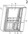
- the in the Figures 1 to 3 The heat dissipation arrangement shown is a so-called multifunction housing, which is used in particular for telecommunications applications.
- the control cabinet housing 1 has in its interior 2 a module housing 4, within which components which have a power loss and require cooling are accommodated. These components can be, for example, the components of an MSAN (Multi Service Access Node).
- MSAN Multi Service Access Node
- the module housing 4 has at least one fan (not shown), via which cooling air is blown into the module housing 4 from the interior of the control cabinet via at least one cooling air inlet 5.
- the cooling air inlet 5 is arranged on an underside of the module housing 4.
- the module housing 4 has a warm air outlet 6, which opens out via an inner side 13 into a rear wall 3 designed as a double wall, so that the hot air from the module housing 4 directly into an intermediate space between the inner side 13 and the outer side 9 the rear wall 3 is initiated.
- the air duct 8 Immediately after the warm air has entered the air duct 8 via the warm air inlet 7, the air duct 8 initially extends in a horizontal direction, so that the warm air runs along the upper end of the Rear wall 3 and immediately below a dormer 11 of the control cabinet housing 1 is perpendicular to the opposite side walls 16 or perpendicular to the end faces 15 of the rear wall 3.
- the air duct 8 has a further warm air outlet 6.1 directly downstream of the warm air inlet in the air flow direction, which opens into the dormer 11, so that at least some of the warm air flowing into the air duct 8 via the warm air inlet 7 flows into the duct via the further warm air inlet 6.1 Roof dormer 11 and can escape into the surroundings of the control cabinet housing 1.
- the cooled warm air is guided past a plurality of cooling air inlets 5.1, which are open to the surroundings of the control cabinet housing 1, before they enter the interior 2 of the control cabinet 1 via a plurality of cooling air outlets 10. Since the cooled air moves essentially parallel to the opening cross section of the further cooling air inlets 5.1, cool ambient air is sucked into the air duct 8 via the further cooling air inlets 5.1 due to the Venturi effect and transported back into the interior 2 of the control cabinet housing 1 with the cooled warm air. An additional cooling capacity is provided in this way.
- the further cooling air inlets 5.1 can open into the base 12 of the control cabinet housing 1 below the interior 2, the base 12 in turn being ventilated to the surroundings of the control cabinet housing 1.
- the plurality of parallel and horizontal air guiding elements 14 extend between the inside 13 and the outside 9, the air guiding elements 14 between them delimiting the air duct 8 in the vertical direction.
- the air guiding elements 14 continue to extend alternately starting from opposite end faces 15 of the rear wall 3 and each reaching a distance up to the opposite end face. In this way it is achieved that between the inner side 13 and the outer side 9 and between the adjacent air guiding elements the air duct 8 is formed, through which the warm air entering via the warm air inlet 7 is led in a meandering manner for the most effective cooling possible to the cooling air outlets 10 of the air duct 8 .
Description
Die Erfindung geht aus von einer Entwärmungsanordnung für einen Schaltschrank, die ein Schaltschrankgehäuse und ein im Innenraum dieses aufgenommenes, an einer Rückwand des Schaltschrankgehäuses montiertes Baugruppengehäuse zur Aufnahme mindestens einer eine thermische Verlustleistung aufweisenden Komponente aufweist. Das Baugruppengehäuse weist mindestens einen Lüfter, einen Kühllufteinlass und einen Warmluftauslass auf, wobei über den Lüfter Kühlluft aus dem Schaltschrankgehäuse in das Baugruppengehäuse hinein, durch das Baugruppengehäuse hindurch und über den Warmluftauslass als erwärmte Kühlluft aus dem Baugruppengehäuse herausgeführt ist. Eine derartige Entwärmungsanordnung ist aus der
Bei den aus dem Stand der Technik bekannten Entwärmungsanordnungen ist es üblich, die für die Abführung der Verlustleistung erforderliche Kühlluft zumindest bedarfsweise bei hohen Umgebungstemperaturen über einen Kompressorkreislauf, etwa eine Kältemaschine, zur Verfügung zu stellen, die zumindest dann aktiv ist, wenn eine passive Kühlung des Baugruppengehäuses im Umluftbetrieb, bei dem Luft aus dem Inneren des Schaltschrankgehäuses in das Baugruppengehäuse eingeblasen und als erwärmte Luft wieder in den Innenraum des Schaltschranks zurückgeblasen wird, unzureichend ist. Dies ist immer dann der Fall, wenn die Umgebungstemperatur des Schaltschrankgehäuses so hoch sind, dass die für eine dissipative Kühlung der im Schaltschrankinnenraum aufgenommene Luft über die Schaltschrankgehäuseoberfläche erforderliche Temperaturdifferenz zwischen Schaltschrankinnenraum und Umgebung des Schaltschrankgehäuses nicht vorliegt. Kompressorbetriebene Kühlkreisläufe, oder auch Kühlkreisläufe, welche mit einem aktiven Luft-/Luft-Wärmetauscher ausgestattet sind, weisen jedoch einen vergleichsweise hohen Energieverbrauch auf.In the heat dissipation arrangements known from the prior art, it is customary to provide the cooling air required for the dissipation of the power loss at least as required at high ambient temperatures via a compressor circuit, for example a refrigeration machine, which is at least active when passive cooling of the Module housing in air recirculation mode, in which air is blown from the inside of the control cabinet housing into the module housing and blown back into the interior of the control cabinet as heated air, is insufficient. This is always the case when the ambient temperature of the control cabinet housing is so high that the temperature difference between the interior of the control cabinet and the surroundings of the control cabinet housing required for dissipative cooling of the air absorbed in the interior of the control cabinet is not present. Compressor-operated cooling circuits or cooling circuits that are equipped with an active air / air heat exchanger, however, have a comparatively high energy consumption.
Es ist daher die Aufgabe der Erfindung, eine Entwärmungsanordnung der zuvor beschriebenen Art derart weiterzuentwickeln, dass sie die energieeffiziente Kühlung der in dem Baugruppengehäuse aufgenommenen Komponenten ermöglicht.It is therefore the object of the invention to further develop a cooling arrangement of the type described above in such a way that it enables the energy-efficient cooling of the components accommodated in the assembly housing.
Diese Aufgabe wird durch eine Entwärmungsanordnung mit den Merkmalen des Anspruchs 1 gelöst. Der nebengeordnete Anspruch 11 betrifft ein entsprechendes Verfahren für die Entwärmung eines Schaltschrankgehäuses. Beispielhafte Ausführungsformen sind Gegenstand der abhängigen Ansprüche.This object is achieved by a cooling arrangement with the features of claim 1. The
Demgemäß ist bei einer Entwärmungsanordnung der eingangs beschriebenen Art vorgesehen, dass der Warmluftauslass des Baugruppengehäuses in einen Warmlufteinlass eines Luftführungskanals in der Rückwand des Schaltschrankgehäuses mündet, wobei der Luftführungskanal durch die Rückwand geführt und mit einer Außenseite der Rückwand thermisch gekoppelt und/oder von dieser begrenzt ist, und wobei mindestens ein Kühlluftauslass des Luftführungskanals in den Innenraum des Schaltschrankgehäuses mündet.Accordingly, in the case of a cooling arrangement of the type described in the introduction, it is provided that the hot air outlet of the module housing opens into a hot air inlet of an air duct in the rear wall of the control cabinet housing, the air duct being guided through the rear wall and thermally coupled to and / or limited by an outer side of the rear wall , and wherein at least one cooling air outlet of the air duct opens into the interior of the control cabinet housing.
Dadurch, dass bei der beschriebenen Entwärmungsanordnung die Rückwand die Funktion eines Wärmetauschers aufweist, bei dem über den Luftführungskanal zu entwärmende Luft durch die Rückwand geführt wird und der Luftführungskanal mit einer Außenseite der Rückwand thermisch gekoppelt ist, wird die dissipative Rückkühlleistung des Schaltschrankgehäuses gegenüber den aus dem Stand der Technik bekannten Schaltschrankgehäusen erhöht, so dass auch für geringere Differenzen ΔT zwischen Schaltschrankinnenraumtemperatur und Umgebungstemperatur noch eine ausreichende Rückkühlung der im Schaltschrankgehäuse enthaltenen Luft gewährleistet ist und dementsprechend auf die Verwendung energieuneffizienter Mittel zur Kälteerzeugung, insbesondere auf Kältemaschinen und dergleichen verzichtet werden kann.Characterized in that in the described heat dissipation arrangement, the rear wall has the function of a heat exchanger, in which air to be warmed via the air duct is led through the rear wall and the air duct is thermally coupled to an outside of the rear wall, the dissipative cooling capacity of the control cabinet housing is compared to that from the State-of-the-art control cabinet housings increased, so that even for smaller differences ΔT between the control cabinet interior temperature and ambient temperature, sufficient cooling of the air contained in the control cabinet housing is still ensured and, accordingly, the use of energy-inefficient means for cooling, in particular on refrigeration machines and the like, can be dispensed with.
Der Warmlufteinlass kann um einen vertikalen Abstand oberhalb von dem Kühlluftauslass angeordnet sein. Dadurch kann erreicht werden, dass die zu kühlende Luft im Wesentlichen in vertikaler Richtung durch die Rückwand geführt und insbesondere in einem unteren Bereich des Schaltschrankgehäuses zurück in den Innenraum des Schaltschrankgehäuses eingeleitet wird, um beispielsweise über die Unterseite des Baugruppengehäuses als gekühlte Luft über den Kühllufteinlass des Baugruppengehäuses angesogen zu werden.The warm air inlet can be arranged a vertical distance above the cooling air outlet. It can thereby be achieved that the air to be cooled is guided essentially in the vertical direction through the rear wall and, in particular, is introduced back into the interior of the control cabinet housing in a lower region of the control cabinet housing, in order, for example, to use the underside of the module housing as cooled air via the cooling air inlet of the Module housing to be sucked.
Der Luftführungskanal kann dem Warmlufteinlass in Luftströmungsrichtung durch den Luftführungskanal unmittelbar nachgelagert oder diesem beigeordnet einen weiteren Warmluftauslass aufweisen, der mittelbar oder unmittelbar zur Umgebung des Schaltschrankgehäuses geöffnet ist. Dies ermöglicht es, dass aufgrund eines lokalen Luftüberdrucks in dem Luftführungskanal ein Teil der Warmluft aus dem Schaltschrankgehäuse ausgeblasen wird.The air duct can immediately follow the warm air inlet in the air flow direction through the air duct or have a further warm air outlet associated therewith, which is open directly or indirectly to the surroundings of the control cabinet housing. This enables a part of the warm air to be blown out of the control cabinet housing due to a local air overpressure in the air duct.
Beispielsweise kann der weitere Warmluftauslass in eine Dachgaube des Schaltschrankgehäuses münden, die wiederum zur Umgebung des Schaltschrankgehäuses entlüftet ist.For example, the further warm air outlet can open into a dormer window of the control cabinet housing, which in turn is vented to the surroundings of the control cabinet housing.
Der Luftführungskanal kann dem Kühlluftauslass in Luftströmungsrichtung durch den Luftführungskanal unmittelbar vorgelagert oder diesem beigeordnet einen weiteren Kühllufteinlass aufweisen, der zur Umgebung des Schaltschrankgehäuses geöffnet ist. Dies ermöglicht es, dass entsprechend dem Venturi-Effekt aufgrund der an dem Kühllufteinlass vorbeiströmenden abgekühlten Warmluft, kühle Luft aus der Schaltschankumgebung in den Luftführungskanal gesogen wird.The air duct can directly precede the cooling air outlet in the air flow direction through the air duct or have a further cooling air inlet associated therewith, which is open to the surroundings of the control cabinet housing. This makes it possible, in accordance with the Venturi effect, for cool air to be drawn into the air duct from the switch cabinet environment due to the cooled warm air flowing past the cooling air inlet.
Der weitere Kühllufteinlass kann in einen Sockel des Schaltschrankgehäuses unterhalb des Innenraums münden, wobei der Sockel wiederum zur Umgebung des Schaltschrankgehäuses belüftet ist.The further cooling air inlet can open into a base of the control cabinet housing below the interior, the base in turn being ventilated to the surroundings of the control cabinet housing.
Der Luftführungskanal ist mäanderförmig durch die Rückwand geführt. Dadurch wird bei gegebener Luftströmungsgeschwindigkeit die Verweildauer der die Rückwand durchströmenden Luft und damit die thermische Kontaktdauer mit der Außenseite der Rückwand und dementsprechend ein noch effektiverer Abtausch der in der Luft enthaltenen thermischen Energie an die Umgebung des Schaltschrankgehäuses erreicht.The air duct is meandering through the rear wall. As a result, the dwell time of the air flowing through the rear wall and thus the thermal contact time with the outside of the rear wall and, accordingly, an even more effective exchange of the thermal energy contained in the air to the environment of the control cabinet housing is achieved at a given air flow rate.
Die Rückwand kann eine dem Innenraum des Schaltschrankgehäuses zugewandte Innenseite und eine unter einem Abstand zu der Innenseite angeordnete und der Umgebung des Schaltschrankgehäuses zugewandte Außenseite aufweisen, wobei der Luftführungskanal von der Außenseite und von der Innenseite begrenzt ist. Die Rückwand kann beispielsweise doppelwandig ausgeführt sein, mit zwei parallel beabstandeten Seiten, von denen eine erste Seite die Innenseite und eine zweite Seite die Außenseite bildet. Der Luftführungskanal kann in der Richtung senkrecht zu der Rückwand gerade durch die Außenseite und die Innenseite begrenzt sein. Zwischen der Innenseite und der Außenseite der Rückwand können Luftleitelemente aufgenommen sein, welche verhindern, dass die durch die Rückwand geführte Luft auf kürzestem Wege von dem Warmlufteinlass zu dem Kühlluftauslass gelangt, so dass die effektive Verweildauer der Kühlluft in der Rückwand bei gegebener Strömungsgeschwindigkeit der Luft erhöht und damit der Wärmeabtausch der durch die Rückwand geleiteten Luft an die Umgebung des Schaltschrankgehäuses über die komplette Oberfläche der Rückwand entsprechend verbessert wird.The rear wall can have an inside facing the interior of the control cabinet housing and an outside arranged at a distance from the inside and facing the surroundings of the control cabinet housing, the air duct being delimited from the outside and from the inside. The rear wall can, for example, be double-walled, with two parallel spaced sides, a first side forming the inside and a second side forming the outside. The air duct can be delimited in the direction perpendicular to the rear wall by the outside and the inside. Air guiding elements can be accommodated between the inside and the outside of the rear wall, which prevent the air guided through the rear wall from getting from the warm air inlet to the cooling air outlet in the shortest possible way, so that the effective residence time of the cooling air in the rear wall increases for a given air flow rate and thus the heat exchange of the air conducted through the rear wall to the surroundings of the control cabinet housing is correspondingly improved over the entire surface of the rear wall.
Zwischen der Innenseite und der Außenseite sowie angrenzend an diese kann sich mindestens ein Luftleitelement erstrecken, über das die durch den Luftführungskanal geleitete Luft mäanderförmig geführt ist.At least one air guiding element can extend between the inside and the outside and adjacent to it, via which the air guided through the air duct is guided in a meandering manner.
Eine Mehrzahl paralleler und horizontaler Luftleitelemente kann sich zwischen der Innenseite und der Außenseite erstrecken, wobei die Luftleitelemente zwischen sich den Luftführungskanal begrenzen, sich abwechselnd ausgehend von gegenüberliegenden Stirnseiten der Rückwand erstrecken und jeweils unter Einhaltung eines Abstands bis an die jeweils gegenüberliegende Stirnseite heranreichen.A plurality of parallel and horizontal air guiding elements can extend between the inside and the outside, the air guiding elements delimiting the air duct between them, extending alternately starting from opposite end faces of the rear wall and each reaching a distance up to the opposite end face.
Gemäß einem anderen Aspekt wird ein Verfahren für die Entwärmung eines Schaltschrankgehäuses beschrieben, das die Schritte aufweist:
- Einblasen von Warmluft aus einem im Innenraum des Schaltschrankgehäuses aufgenommenen, an einer Rückwand des Schaltschrankgehäuses montierten Baugruppengehäuse zur Aufnahme mindestens einer eine thermische Verlustleistung aufweisenden Komponente in einen durch die Rückwand geleiteten Luftführungskanal;
- Durchleiten der Warmluft durch den Luftführungskanal und Ausblasen der Warmluft als gekühlte Luft in den Innenraum des Schaltschranks; und
- Einleiten der gekühlten Luft im Innenraum des Schaltschrankgehäuses in das Baugruppengehäuse
- Blowing hot air from a module housing, which is accommodated in the interior of the control cabinet housing and is mounted on a rear wall of the control cabinet housing, for receiving at least one component which has a thermal power loss into an air duct which is guided through the rear wall;
- Directing the warm air through the air duct and blowing out the warm air as cooled air into the interior of the control cabinet; and
- Introduce the cooled air in the interior of the control cabinet housing into the module housing
Ebenso wird vorzugsweise bei dem Einblasen von Warmluft in den Luftführungskanal ein Teil der Warmluft in die Umgebung entlassen.Likewise, when warm air is blown into the air duct, part of the warm air is preferably released into the environment.
Weitere Einzelheiten der Erfindung werden anhand der nachstehenden Figuren erläutert. Diese zeigen:
- Figur 1
- eine Entwärmungsanordnung in perspektivischer Sicht auf die Vorderseite sowie mit entfernten Türelementen;
Figur 2- die Ausführungsform gemäß
Figur 1 mit perspektivischer Sicht auf die Vorderseite von schräg unten; und Figur 3- eine Rückansicht der Ausführungsform gemäß den
Figuren 1 und2 , wobei zur besseren Veranschaulichung die Außenseite der Rückwand des Schaltschrankgehäuses entfernt wurde.
- Figure 1
- a cooling arrangement in a perspective view of the front and with the door elements removed;
- Figure 2
- the embodiment according to
Figure 1 with a perspective view of the front from obliquely below; and - Figure 3
- a rear view of the embodiment according to the
Figures 1 and2nd , whereby the outside of the rear wall of the control cabinet housing has been removed for better illustration.
Die in den
Das Baugruppengehäuse 4 weist mindestens einen Lüfter (nicht dargestellt) auf, über den Kühlluft aus dem Schaltschrankinnenraum über mindestens einen Kühllufteinlass 5 in das Baugruppengehäuse 4 eingeblasen ist. Der Kühllufteinlass 5 ist an einer Unterseite des Baugruppengehäuses 4 angeordnet. An einem der Unterseite abgewandten oberen Ende weist das Baugruppengehäuse 4 einen Warmluftauslass 6 auf, der über eine Innenseite 13 in eine als Doppelwand ausgebildete Rückwand 3 mündet, so dass die Warmluft aus dem Baugruppengehäuse 4 unmittelbar in einen Zwischenraum zwischen der Innenseite 13 und der Außenseite 9 der Rückwand 3 eingeleitet ist.The
Zwischen der Innenseite 13 und der Außenseite 9 der Rückwand 3 ist eine Mehrzahl Luftleitelemente 14 angeordnet, welche im Zusammenwirken mit der Innenseite 13 und der Außenseite 9 einen Luftführungskanal 8 bilden, über den die über den Warmlufteinlass 7 in den Luftführungskanal 8 eintretende Warmluft mäanderförmig von einem oberen Ende der Rückwand 3 zu einem unteren Ende der Rückwand 3 geführt wird, um dort über Kühlluftauslässe 10 zurück in den Innenraum 2 des Schaltschrankgehäuses 1 geführt zu werden.Between the
Unmittelbar nachdem die Warmluft über den Warmlufteinlass 7 in den Luftführungskanal 8 eingetreten ist, erstreckt sich der Luftführungskanal 8 zunächst in einer Horizontalrichtung, so dass die Warmluft entlang des oberen Endes der Rückwand 3 sowie unmittelbar unterhalb einer Dachgaube 11 des Schaltschrankgehäuses 1 senkrecht zu den gegenüberliegenden Seitenwänden 16 beziehungsweise senkrecht zur den Stirnseiten 15 der Rückwand 3 geführt ist. Der Luftführungskanal 8 weist in diesem ersten Abschnitt unmittelbar dem Warmlufteinlass in Luftströmungsrichtung nachgelagert einen weiteren Warmluftauslass 6.1 auf, der in die Dachgaube 11 mündet, so dass zumindest ein Teil der über den Warmlufteinlass 7 in den Luftführungskanal 8 einströmenden Warmluft über den weiteren Warmlufteinlass 6.1 in die Dachgaube 11 und über diese in die Umgebung des Schaltschrankgehäuses 1 entweichen kann.Immediately after the warm air has entered the
Am unteren Ende des Luftführungskanals wird die abgekühlte Warmluft, bevor sie über eine Mehrzahl Kühlluftauslässe 10 zurück in den Innenraum 2 des Schaltschranks 1 eintritt, an einer Mehrzahl Kühllufteinlässe 5.1 vorbeigeführt, die zur Umgebung des Schaltschrankgehäuses 1 geöffnet sind. Da sich die gekühlte Luft im Wesentlichen parallel zum Öffnungsquerschnitt der weiteren Kühllufteinlässe 5.1 bewegt, wird aufgrund des Venturi-Effekts kühle Umgebungsluft über die weiteren Kühllufteinlässe 5.1 in den Luftführungkanal 8 eingesogen und mit der abgekühlten Warmluft zurück in den Innenraum 2 des Schaltschrankgehäuses 1 transportiert. Auf diese Weise wird eine zusätzliche Kühlleistung bereitgestellt. Die weiteren Kühllufteinlässe 5.1 können in den Sockel 12 des Schaltschrankgehäuses 1 unterhalb des Innenraums 2 münden, wobei der Sockel 12 wiederum zur Umgebung des Schaltschrankgehäuses 1 belüftet ist.At the lower end of the air duct, the cooled warm air is guided past a plurality of cooling air inlets 5.1, which are open to the surroundings of the control cabinet housing 1, before they enter the
Die Mehrzahl paralleler und horizontaler Luftleitelemente 14 erstreckt sich zwischen der Innenseite 13 und der Außenseite 9, wobei die Luftleitelemente 14 zwischen sich den Luftführungskanal 8 in Vertikalrichtung begrenzen. Die Luftleitelemente 14 erstrecken sich weiterhin abwechselnd ausgehend von gegenüberliegenden Stirnseiten 15 der Rückwand 3 und reichen jeweils unter Einhaltung eines Abstands bis an die jeweils gegenüberliegende Stirnseite heran. Auf diese Weise wird erreicht, dass zwischen der Innenseite 13 und der Außenseite 9 sowie zwischen den benachbarten Luftleitelementen der Luftführungskanal 8 gebildet ist, durch den die über den Warmlufteinlass 7 eintretende Warmluft zur möglichst effektiven Abkühlung mäanderförmig bis zu den Kühlluftauslässen 10 des Luftführungskanals 8 geführt ist.The plurality of parallel and horizontal
Die in der vorstehenden Beschreibung, in den Zeichnungen sowie in den Ansprüchen offenbarten Merkmale der Erfindung können sowohl einzeln als auch in beliebiger Kombination für die Verwirklichung der Erfindung wesentlich sein.The features of the invention disclosed in the above description, in the drawings and in the claims can be essential for realizing the invention both individually and in any combination.
- 11
- SchaltschrankgehäuseControl cabinet housing
- 22nd
- Innenrauminner space
- 33rd
- RückwandBack wall
- 44th
- BaugruppengehäuseModule housing
- 55
- KühllufteinlassCooling air intake
- 5.15.1
- weiterer Kühllufteinlassfurther cooling air inlet
- 66
- WarmluftauslassWarm air outlet
- 6.16.1
- weiterer Warmluftauslassfurther warm air outlet
- 77
- WarmlufteinlassWarm air intake
- 88th
- LuftführungskanalAir duct
- 99
- AußenseiteOutside
- 1010th
- KühlluftauslassCooling air outlet
- 11.11.
- DachgaubeDormer window
- 1212th
- Sockelbase
- 1313
- Innenseiteinside
- 1414
- LuftleitelementAir control element
- 1515
- StirnseiteFace
- 1616
- SeitenwandSide wall
Claims (13)
- A heat dissipation arrangement for a switch cabinet, which has a switch cabinet housing (1) and a subassembly housing (4), which is accommodated in the interior (2) thereof and is mounted on a rear wall (3) of the switch cabinet housing (1), for accommodating at least one component having a thermal power loss, the subassembly housing (4) having at least one fan, a cooling air inlet (5) and a warm air outlet (6), wherein by means of the fan cooling air is guided from the switch cabinet housing (1) into the assembly housing (4), through the assembly housing (4) and out of the assembly housing (4) via the warm air outlet (6) as heated cooling air, wherein the warm air outlet (6) of the assembly housing (4) opens into a warm air inlet (7) of an air guide channel (8) in the rear wall (3) of the switch cabinet housing (1), wherein the air guide channel (8) is guided through the rear wall (3) and is thermally coupled to an outer side (9) of the rear wall (3) and/or is limited by the latter, and wherein at least one cooling air outlet (10) of the air duct (8) opens into the interior (2) of the switch cabinet housing (1), characterised in that the air duct (8) is guided in meandering manner through the rear wall (3).
- The heat dissipation arrangement according to claim 1, in which the warm air inlet (7) is arranged at a vertical distance above the cooling air outlet (10).
- The heat dissipation arrangement according to claim 1 or 2, in which the air duct (8) has a further warm air outlet (6.1) directly downstream of the warm air inlet (7) in the direction of air flow through the air duct (8) or associated therewith, which is open directly or indirectly to the surroundings of the switch cabinet housing (1).
- The heat dissipation arrangement according to claim 3, in which the further warm air outlet (6.1) opens into a roof dormer (11) of the switch cabinet housing (1), which is vented to the surroundings of the switch cabinet housing (1).
- The heat dissipation arrangement according to one of the preceding claims, in which the air duct (8) has a further cooling air inlet (5.1), which is open to the surroundings of the switch cabinet housing (1), directly upstream of the cooling air outlet (10) in the air flow direction through the air duct (8) or associated therewith.
- The heat dissipation arrangement according to claim 5, in which the further cooling air inlet (5.1) opens into a base (12) of the switch cabinet housing (1) below the interior (2), which is ventilated to the surroundings of the switch cabinet housing (1).
- The heat dissipation arrangement according to one of the preceding claims, in which the rear wall (3) has an inner side (13) facing the interior (2) of the switch cabinet housing (1) and an outer side (9) arranged at a distance from the inner side (13) and facing the surroundings of the switch cabinet housing (1), the air duct (8) being bounded by the outer side (9) and the inner side (13).
- The heat dissipation arrangement according to claim 7, in which at least one air guide element (14) extends between the inner side (13) and the outer side (9) and adjoining the latter, over which air guide element the air conducted through the air guide channel (8) is guided, in particular in a meandering manner.
- The heat dissipation arrangement according to claim 7 or 8, in which a plurality of parallel and horizontal air guide elements (14) extend between the inner side (13) and the outer side (9), which define between them the air guide channel (8) and which extend alternately starting from opposite end faces (15) of the rear wall (3) and in each case reach up to the respective opposite end face (15) while maintaining a distance.
- A method for the heat dissipation of a switch cabinet housing (1), which comprises the steps:- blowing warm air from a subassembly housing (4), which is accommodated in the interior (2) of the switchgear cabinet housing (1) and is mounted on a rear wall (3) of the switchgear cabinet housing (1), for accommodating at least one component, which has a thermal power loss, in an air duct (8) guided through the rear wall (3);- passing the warm air through the air duct (8) and blowing the warm air as cooled air into the interior (2) of the switch cabinet; and- introducing the cooled air in the interior (2) of the switch cabinet housing (1) into the subassembly housing (4),
characterised in that passing of the warm air comprises passing of the warm air through the air guide channel (8) in a meandering manner. - The method according to claim 10, in which ambient air is added to the cooled air during the blowing out of the cooled air into the interior (2) of the switch cabinet housing (1).
- The method according to claim 10 or 11, in which, when warm air is blown into the air duct (8), part of the warm air is released into the environment.
- The method according to one of claims 10 to 12, in which, when passing through, thermal energy of the warm air is exchanged via an outer side (9) of the rear wall (3) which delimits the air duct (8).
Applications Claiming Priority (2)
| Application Number | Priority Date | Filing Date | Title |
|---|---|---|---|
| DE102017109997.2A DE102017109997B3 (en) | 2017-05-09 | 2017-05-09 | Cooling arrangement for a control cabinet |
| PCT/DE2018/100216 WO2018206030A1 (en) | 2017-05-09 | 2018-03-09 | Heat dissipation arrangement for a switchgear cabinet |
Publications (2)
| Publication Number | Publication Date |
|---|---|
| EP3583668A1 EP3583668A1 (en) | 2019-12-25 |
| EP3583668B1 true EP3583668B1 (en) | 2020-07-08 |
Family
ID=61865896
Family Applications (1)
| Application Number | Title | Priority Date | Filing Date |
|---|---|---|---|
| EP18717502.1A Active EP3583668B1 (en) | 2017-05-09 | 2018-03-09 | Heat dissipation device for an electrical cabinet |
Country Status (5)
| Country | Link |
|---|---|
| EP (1) | EP3583668B1 (en) |
| DE (1) | DE102017109997B3 (en) |
| ES (1) | ES2813276T3 (en) |
| HU (1) | HUE052085T2 (en) |
| WO (1) | WO2018206030A1 (en) |
Families Citing this family (4)
| Publication number | Priority date | Publication date | Assignee | Title |
|---|---|---|---|---|
| DE102019134796B4 (en) * | 2019-12-17 | 2023-02-02 | Langmatz Gmbh | distribution cabinet |
| CN112383007B (en) * | 2020-10-22 | 2021-12-07 | 江苏向荣电气有限公司 | Intelligent bus duct with good heat dissipation effect |
| CN112382962A (en) * | 2020-10-23 | 2021-02-19 | 河北电力装备有限公司 | Inlet lap joint ventilation mechanism |
| CN113314995B (en) * | 2021-06-05 | 2022-12-20 | 河南亚盛电气有限责任公司 | Building control cabinet |
Family Cites Families (8)
| Publication number | Priority date | Publication date | Assignee | Title |
|---|---|---|---|---|
| DE19812117A1 (en) | 1998-03-19 | 1999-09-23 | Knuerr Mechanik Ag | Equipment cabinet |
| JP2005044857A (en) | 2003-07-23 | 2005-02-17 | Kyocera Corp | Cooling mechanism |
| FI20055428A (en) | 2005-08-08 | 2007-02-09 | Abb Oy | instrument cabinet |
| DE102007040594A1 (en) | 2007-01-24 | 2008-07-31 | Brahms, Martin, Dipl.-Ing. | Method for tempering multifunctional housing, involves arranging temperature sensor in multifunctional housing, and intelligent electronic switch is attached at blower |
| US7826216B2 (en) * | 2008-10-08 | 2010-11-02 | Dell Products L.P. | Information handling center cooling system |
| DE102012001119B4 (en) | 2012-01-23 | 2022-11-17 | Sew-Eurodrive Gmbh & Co Kg | Control cabinet with housing containing centrally ventilated modules for heat dissipation |
| US10028414B2 (en) * | 2014-06-24 | 2018-07-17 | Vertiv Energy Systems, Inc. | Passive cooling features for electronics equipment cabinets |
| US10015914B2 (en) * | 2015-02-05 | 2018-07-03 | Vertiv Energy Systems, Inc. | Enclosures and methods of managing heat in heat generating modules |
-
2017
- 2017-05-09 DE DE102017109997.2A patent/DE102017109997B3/en active Active
-
2018
- 2018-03-09 HU HUE18717502A patent/HUE052085T2/en unknown
- 2018-03-09 ES ES18717502T patent/ES2813276T3/en active Active
- 2018-03-09 EP EP18717502.1A patent/EP3583668B1/en active Active
- 2018-03-09 WO PCT/DE2018/100216 patent/WO2018206030A1/en active Search and Examination
Non-Patent Citations (1)
| Title |
|---|
| None * |
Also Published As
| Publication number | Publication date |
|---|---|
| DE102017109997B3 (en) | 2018-04-26 |
| EP3583668A1 (en) | 2019-12-25 |
| ES2813276T3 (en) | 2021-03-23 |
| WO2018206030A1 (en) | 2018-11-15 |
| HUE052085T2 (en) | 2021-04-28 |
Similar Documents
| Publication | Publication Date | Title |
|---|---|---|
| EP3583668B1 (en) | Heat dissipation device for an electrical cabinet | |
| EP1967938B1 (en) | Control cabinet for electronic plug-in components with a heat exchanger | |
| EP1832150B1 (en) | Cooling system for appliance cabinets and network cabinets, and method for cooling appliance cabinets and network cabinets | |
| EP1544553B1 (en) | Arrangement for conditioning recirculation air, in particular clean air | |
| DE102009054011B4 (en) | Cooling arrangement for arranged in a cabinet electrical equipment | |
| WO2007134695A1 (en) | Electrical cabinet with two cooling channels | |
| DE102015105493B3 (en) | Control cabinet arrangement with a control cabinet row and a cooling unit arranged in it | |
| DE102015105490B3 (en) | Cooling device for cooling the air taken in the interior of a cabinet and a corresponding control cabinet assembly | |
| EP2346052B1 (en) | Housing for an electric machine | |
| EP2839724B1 (en) | Cooling apparatus for control cabinet cooling | |
| DE102006052122B4 (en) | Air conditioning device | |
| EP3221646B1 (en) | Method and arrangement for air-conditioning a cold aisle | |
| DE102014201483B4 (en) | Cuboid housing for an electronics module, electronic module and arrangement for cooling at least one electronic module | |
| EP0059410A2 (en) | Casing to house electric and/or electronic elements | |
| EP2434853A1 (en) | Air conditioning device for cooling air for an electronics cabinet or similar | |
| DE102009030088B4 (en) | casing | |
| EP4016783B1 (en) | Charger with charging electronics unit and cooling air guiding structure | |
| EP3024310B1 (en) | Air conditioning assembly | |
| EP3149817B1 (en) | Air conditioning assembly | |
| DE202013103846U1 (en) | Filter fan arrangement for cooling a control cabinet | |
| DE102015101022B3 (en) | Data Center | |
| EP2326158B1 (en) | Equipment locker | |
| DE10210418A1 (en) | Switch cupboard with cooling arrangement for built-in elements, superimposes air sucked in and out by ventilators on a cool air stream fed to the ambient air in the switch cupboard. | |
| WO2023061536A1 (en) | Data centre having a row of switch cabinets arranged in a container and a partition between a cold aisle and a hot aisle | |
| DE102014101453A1 (en) | Control cabinet with air conditioning device |
Legal Events
| Date | Code | Title | Description |
|---|---|---|---|
| STAA | Information on the status of an ep patent application or granted ep patent |
Free format text: STATUS: UNKNOWN |
|
| STAA | Information on the status of an ep patent application or granted ep patent |
Free format text: STATUS: THE INTERNATIONAL PUBLICATION HAS BEEN MADE |
|
| PUAI | Public reference made under article 153(3) epc to a published international application that has entered the european phase |
Free format text: ORIGINAL CODE: 0009012 |
|
| STAA | Information on the status of an ep patent application or granted ep patent |
Free format text: STATUS: REQUEST FOR EXAMINATION WAS MADE |
|
| 17P | Request for examination filed |
Effective date: 20190918 |
|
| AK | Designated contracting states |
Kind code of ref document: A1 Designated state(s): AL AT BE BG CH CY CZ DE DK EE ES FI FR GB GR HR HU IE IS IT LI LT LU LV MC MK MT NL NO PL PT RO RS SE SI SK SM TR |
|
| AX | Request for extension of the european patent |
Extension state: BA ME |
|
| GRAP | Despatch of communication of intention to grant a patent |
Free format text: ORIGINAL CODE: EPIDOSNIGR1 |
|
| STAA | Information on the status of an ep patent application or granted ep patent |
Free format text: STATUS: GRANT OF PATENT IS INTENDED |
|
| DAV | Request for validation of the european patent (deleted) | ||
| DAX | Request for extension of the european patent (deleted) | ||
| INTG | Intention to grant announced |
Effective date: 20200402 |
|
| GRAS | Grant fee paid |
Free format text: ORIGINAL CODE: EPIDOSNIGR3 |
|
| GRAA | (expected) grant |
Free format text: ORIGINAL CODE: 0009210 |
|
| STAA | Information on the status of an ep patent application or granted ep patent |
Free format text: STATUS: THE PATENT HAS BEEN GRANTED |
|
| AK | Designated contracting states |
Kind code of ref document: B1 Designated state(s): AL AT BE BG CH CY CZ DE DK EE ES FI FR GB GR HR HU IE IS IT LI LT LU LV MC MK MT NL NO PL PT RO RS SE SI SK SM TR |
|
| REG | Reference to a national code |
Ref country code: CH Ref legal event code: EP Ref country code: AT Ref legal event code: REF Ref document number: 1289485 Country of ref document: AT Kind code of ref document: T Effective date: 20200715 |
|
| REG | Reference to a national code |
Ref country code: DE Ref legal event code: R096 Ref document number: 502018001861 Country of ref document: DE |
|
| REG | Reference to a national code |
Ref country code: IE Ref legal event code: FG4D Free format text: LANGUAGE OF EP DOCUMENT: GERMAN |
|
| REG | Reference to a national code |
Ref country code: SE Ref legal event code: TRGR |
|
| REG | Reference to a national code |
Ref country code: NL Ref legal event code: FP |
|
| REG | Reference to a national code |
Ref country code: NO Ref legal event code: T2 Effective date: 20200708 |
|
| REG | Reference to a national code |
Ref country code: LT Ref legal event code: MG4D |
|
| PG25 | Lapsed in a contracting state [announced via postgrant information from national office to epo] |
Ref country code: BG Free format text: LAPSE BECAUSE OF FAILURE TO SUBMIT A TRANSLATION OF THE DESCRIPTION OR TO PAY THE FEE WITHIN THE PRESCRIBED TIME-LIMIT Effective date: 20201008 Ref country code: GR Free format text: LAPSE BECAUSE OF FAILURE TO SUBMIT A TRANSLATION OF THE DESCRIPTION OR TO PAY THE FEE WITHIN THE PRESCRIBED TIME-LIMIT Effective date: 20201009 Ref country code: PT Free format text: LAPSE BECAUSE OF FAILURE TO SUBMIT A TRANSLATION OF THE DESCRIPTION OR TO PAY THE FEE WITHIN THE PRESCRIBED TIME-LIMIT Effective date: 20201109 Ref country code: LT Free format text: LAPSE BECAUSE OF FAILURE TO SUBMIT A TRANSLATION OF THE DESCRIPTION OR TO PAY THE FEE WITHIN THE PRESCRIBED TIME-LIMIT Effective date: 20200708 Ref country code: HR Free format text: LAPSE BECAUSE OF FAILURE TO SUBMIT A TRANSLATION OF THE DESCRIPTION OR TO PAY THE FEE WITHIN THE PRESCRIBED TIME-LIMIT Effective date: 20200708 Ref country code: FI Free format text: LAPSE BECAUSE OF FAILURE TO SUBMIT A TRANSLATION OF THE DESCRIPTION OR TO PAY THE FEE WITHIN THE PRESCRIBED TIME-LIMIT Effective date: 20200708 |
|
| PG25 | Lapsed in a contracting state [announced via postgrant information from national office to epo] |
Ref country code: RS Free format text: LAPSE BECAUSE OF FAILURE TO SUBMIT A TRANSLATION OF THE DESCRIPTION OR TO PAY THE FEE WITHIN THE PRESCRIBED TIME-LIMIT Effective date: 20200708 Ref country code: PL Free format text: LAPSE BECAUSE OF FAILURE TO SUBMIT A TRANSLATION OF THE DESCRIPTION OR TO PAY THE FEE WITHIN THE PRESCRIBED TIME-LIMIT Effective date: 20200708 Ref country code: LV Free format text: LAPSE BECAUSE OF FAILURE TO SUBMIT A TRANSLATION OF THE DESCRIPTION OR TO PAY THE FEE WITHIN THE PRESCRIBED TIME-LIMIT Effective date: 20200708 Ref country code: IS Free format text: LAPSE BECAUSE OF FAILURE TO SUBMIT A TRANSLATION OF THE DESCRIPTION OR TO PAY THE FEE WITHIN THE PRESCRIBED TIME-LIMIT Effective date: 20201108 |
|
| REG | Reference to a national code |
Ref country code: ES Ref legal event code: FG2A Ref document number: 2813276 Country of ref document: ES Kind code of ref document: T3 Effective date: 20210323 |
|
| REG | Reference to a national code |
Ref country code: DE Ref legal event code: R097 Ref document number: 502018001861 Country of ref document: DE |
|
| REG | Reference to a national code |
Ref country code: HU Ref legal event code: AG4A Ref document number: E052085 Country of ref document: HU |
|
| PG25 | Lapsed in a contracting state [announced via postgrant information from national office to epo] |
Ref country code: SM Free format text: LAPSE BECAUSE OF FAILURE TO SUBMIT A TRANSLATION OF THE DESCRIPTION OR TO PAY THE FEE WITHIN THE PRESCRIBED TIME-LIMIT Effective date: 20200708 Ref country code: RO Free format text: LAPSE BECAUSE OF FAILURE TO SUBMIT A TRANSLATION OF THE DESCRIPTION OR TO PAY THE FEE WITHIN THE PRESCRIBED TIME-LIMIT Effective date: 20200708 Ref country code: CZ Free format text: LAPSE BECAUSE OF FAILURE TO SUBMIT A TRANSLATION OF THE DESCRIPTION OR TO PAY THE FEE WITHIN THE PRESCRIBED TIME-LIMIT Effective date: 20200708 Ref country code: DK Free format text: LAPSE BECAUSE OF FAILURE TO SUBMIT A TRANSLATION OF THE DESCRIPTION OR TO PAY THE FEE WITHIN THE PRESCRIBED TIME-LIMIT Effective date: 20200708 Ref country code: EE Free format text: LAPSE BECAUSE OF FAILURE TO SUBMIT A TRANSLATION OF THE DESCRIPTION OR TO PAY THE FEE WITHIN THE PRESCRIBED TIME-LIMIT Effective date: 20200708 |
|
| PLBE | No opposition filed within time limit |
Free format text: ORIGINAL CODE: 0009261 |
|
| STAA | Information on the status of an ep patent application or granted ep patent |
Free format text: STATUS: NO OPPOSITION FILED WITHIN TIME LIMIT |
|
| PG25 | Lapsed in a contracting state [announced via postgrant information from national office to epo] |
Ref country code: AL Free format text: LAPSE BECAUSE OF FAILURE TO SUBMIT A TRANSLATION OF THE DESCRIPTION OR TO PAY THE FEE WITHIN THE PRESCRIBED TIME-LIMIT Effective date: 20200708 |
|
| 26N | No opposition filed |
Effective date: 20210409 |
|
| PG25 | Lapsed in a contracting state [announced via postgrant information from national office to epo] |
Ref country code: SK Free format text: LAPSE BECAUSE OF FAILURE TO SUBMIT A TRANSLATION OF THE DESCRIPTION OR TO PAY THE FEE WITHIN THE PRESCRIBED TIME-LIMIT Effective date: 20200708 |
|
| REG | Reference to a national code |
Ref country code: DE Ref legal event code: R119 Ref document number: 502018001861 Country of ref document: DE |
|
| PG25 | Lapsed in a contracting state [announced via postgrant information from national office to epo] |
Ref country code: MC Free format text: LAPSE BECAUSE OF FAILURE TO SUBMIT A TRANSLATION OF THE DESCRIPTION OR TO PAY THE FEE WITHIN THE PRESCRIBED TIME-LIMIT Effective date: 20200708 |
|
| REG | Reference to a national code |
Ref country code: CH Ref legal event code: PL |
|
| REG | Reference to a national code |
Ref country code: BE Ref legal event code: MM Effective date: 20210331 |
|
| PG25 | Lapsed in a contracting state [announced via postgrant information from national office to epo] |
Ref country code: CH Free format text: LAPSE BECAUSE OF NON-PAYMENT OF DUE FEES Effective date: 20210331 Ref country code: DE Free format text: LAPSE BECAUSE OF NON-PAYMENT OF DUE FEES Effective date: 20211001 Ref country code: IE Free format text: LAPSE BECAUSE OF NON-PAYMENT OF DUE FEES Effective date: 20210309 Ref country code: LI Free format text: LAPSE BECAUSE OF NON-PAYMENT OF DUE FEES Effective date: 20210331 Ref country code: LU Free format text: LAPSE BECAUSE OF NON-PAYMENT OF DUE FEES Effective date: 20210309 |
|
| PG25 | Lapsed in a contracting state [announced via postgrant information from national office to epo] |
Ref country code: BE Free format text: LAPSE BECAUSE OF NON-PAYMENT OF DUE FEES Effective date: 20210331 |
|
| PGFP | Annual fee paid to national office [announced via postgrant information from national office to epo] |
Ref country code: NO Payment date: 20230321 Year of fee payment: 6 Ref country code: FR Payment date: 20230320 Year of fee payment: 6 Ref country code: AT Payment date: 20230317 Year of fee payment: 6 |
|
| PGFP | Annual fee paid to national office [announced via postgrant information from national office to epo] |
Ref country code: SE Payment date: 20230315 Year of fee payment: 6 Ref country code: HU Payment date: 20230301 Year of fee payment: 6 Ref country code: GB Payment date: 20230323 Year of fee payment: 6 |
|
| PG25 | Lapsed in a contracting state [announced via postgrant information from national office to epo] |
Ref country code: CY Free format text: LAPSE BECAUSE OF FAILURE TO SUBMIT A TRANSLATION OF THE DESCRIPTION OR TO PAY THE FEE WITHIN THE PRESCRIBED TIME-LIMIT Effective date: 20200708 |
|
| PGFP | Annual fee paid to national office [announced via postgrant information from national office to epo] |
Ref country code: NL Payment date: 20230322 Year of fee payment: 6 |
|
| P01 | Opt-out of the competence of the unified patent court (upc) registered |
Effective date: 20230525 |
|
| PGFP | Annual fee paid to national office [announced via postgrant information from national office to epo] |
Ref country code: IT Payment date: 20230331 Year of fee payment: 6 Ref country code: ES Payment date: 20230414 Year of fee payment: 6 |
|
| PG25 | Lapsed in a contracting state [announced via postgrant information from national office to epo] |
Ref country code: SI Free format text: LAPSE BECAUSE OF FAILURE TO SUBMIT A TRANSLATION OF THE DESCRIPTION OR TO PAY THE FEE WITHIN THE PRESCRIBED TIME-LIMIT Effective date: 20200708 |
|
| PGFP | Annual fee paid to national office [announced via postgrant information from national office to epo] |
Ref country code: NL Payment date: 20240320 Year of fee payment: 7 |