EP1523623B1 - Soupape de regulation de debit non proportionnelle pour pompe a cellules en ailettes - Google Patents
Soupape de regulation de debit non proportionnelle pour pompe a cellules en ailettes Download PDFInfo
- Publication number
- EP1523623B1 EP1523623B1 EP03735598A EP03735598A EP1523623B1 EP 1523623 B1 EP1523623 B1 EP 1523623B1 EP 03735598 A EP03735598 A EP 03735598A EP 03735598 A EP03735598 A EP 03735598A EP 1523623 B1 EP1523623 B1 EP 1523623B1
- Authority
- EP
- European Patent Office
- Prior art keywords
- spring
- valve
- longitudinal region
- valve according
- flow control
- Prior art date
- Legal status (The legal status is an assumption and is not a legal conclusion. Google has not performed a legal analysis and makes no representation as to the accuracy of the status listed.)
- Expired - Lifetime
Links
- 230000000903 blocking effect Effects 0.000 claims 1
- 239000012530 fluid Substances 0.000 description 14
- 238000004804 winding Methods 0.000 description 4
- 230000006835 compression Effects 0.000 description 2
- 238000007906 compression Methods 0.000 description 2
- 238000000418 atomic force spectrum Methods 0.000 description 1
- 230000001419 dependent effect Effects 0.000 description 1
- 210000003746 feather Anatomy 0.000 description 1
- 238000002789 length control Methods 0.000 description 1
- 239000000463 material Substances 0.000 description 1
- 230000000704 physical effect Effects 0.000 description 1
- 230000000750 progressive effect Effects 0.000 description 1
- 230000000087 stabilizing effect Effects 0.000 description 1
Images



Classifications
-
- F—MECHANICAL ENGINEERING; LIGHTING; HEATING; WEAPONS; BLASTING
- F04—POSITIVE - DISPLACEMENT MACHINES FOR LIQUIDS; PUMPS FOR LIQUIDS OR ELASTIC FLUIDS
- F04C—ROTARY-PISTON, OR OSCILLATING-PISTON, POSITIVE-DISPLACEMENT MACHINES FOR LIQUIDS; ROTARY-PISTON, OR OSCILLATING-PISTON, POSITIVE-DISPLACEMENT PUMPS
- F04C14/00—Control of, monitoring of, or safety arrangements for, machines, pumps or pumping installations
- F04C14/24—Control of, monitoring of, or safety arrangements for, machines, pumps or pumping installations characterised by using valves controlling pressure or flow rate, e.g. discharge valves or unloading valves
- F04C14/26—Control of, monitoring of, or safety arrangements for, machines, pumps or pumping installations characterised by using valves controlling pressure or flow rate, e.g. discharge valves or unloading valves using bypass channels
-
- F—MECHANICAL ENGINEERING; LIGHTING; HEATING; WEAPONS; BLASTING
- F04—POSITIVE - DISPLACEMENT MACHINES FOR LIQUIDS; PUMPS FOR LIQUIDS OR ELASTIC FLUIDS
- F04C—ROTARY-PISTON, OR OSCILLATING-PISTON, POSITIVE-DISPLACEMENT MACHINES FOR LIQUIDS; ROTARY-PISTON, OR OSCILLATING-PISTON, POSITIVE-DISPLACEMENT PUMPS
- F04C2/00—Rotary-piston machines or pumps
- F04C2/30—Rotary-piston machines or pumps having the characteristics covered by two or more groups F04C2/02, F04C2/08, F04C2/22, F04C2/24 or having the characteristics covered by one of these groups together with some other type of movement between co-operating members
- F04C2/34—Rotary-piston machines or pumps having the characteristics covered by two or more groups F04C2/02, F04C2/08, F04C2/22, F04C2/24 or having the characteristics covered by one of these groups together with some other type of movement between co-operating members having the movement defined in groups F04C2/08 or F04C2/22 and relative reciprocation between the co-operating members
- F04C2/344—Rotary-piston machines or pumps having the characteristics covered by two or more groups F04C2/02, F04C2/08, F04C2/22, F04C2/24 or having the characteristics covered by one of these groups together with some other type of movement between co-operating members having the movement defined in groups F04C2/08 or F04C2/22 and relative reciprocation between the co-operating members with vanes reciprocating with respect to the inner member
-
- F—MECHANICAL ENGINEERING; LIGHTING; HEATING; WEAPONS; BLASTING
- F04—POSITIVE - DISPLACEMENT MACHINES FOR LIQUIDS; PUMPS FOR LIQUIDS OR ELASTIC FLUIDS
- F04C—ROTARY-PISTON, OR OSCILLATING-PISTON, POSITIVE-DISPLACEMENT MACHINES FOR LIQUIDS; ROTARY-PISTON, OR OSCILLATING-PISTON, POSITIVE-DISPLACEMENT PUMPS
- F04C2270/00—Control; Monitoring or safety arrangements
- F04C2270/20—Flow
-
- F—MECHANICAL ENGINEERING; LIGHTING; HEATING; WEAPONS; BLASTING
- F04—POSITIVE - DISPLACEMENT MACHINES FOR LIQUIDS; PUMPS FOR LIQUIDS OR ELASTIC FLUIDS
- F04C—ROTARY-PISTON, OR OSCILLATING-PISTON, POSITIVE-DISPLACEMENT MACHINES FOR LIQUIDS; ROTARY-PISTON, OR OSCILLATING-PISTON, POSITIVE-DISPLACEMENT PUMPS
- F04C2270/00—Control; Monitoring or safety arrangements
- F04C2270/58—Valve parameters
Definitions
- the invention relates to a valve for a pump with a spring according to the preamble of claim 1.
- the DE 199 48 446 A1 describes a spring for a pump valve, in particular for a suction valve of a pump of a controlled braking system.
- the spring for controlling the opening times of the suction valve of a piston pump has in the work area in which the valve opens a small spring stiffness, while in that work area in which the spring begins to close the valve, a great spring stiffness of the spring is utilized. This causes a quick closing of the valve can take place.
- the DE 19915555 discloses a vane pump with a flow control valve.
- a control piston is mounted axially displaceable in a valve bore preferably in a housing of a vane pump.
- the flow control valve is formed in the manner of a pressure balance, wherein the control piston is acted upon on one side with operating pressure of the vane pump and with a consumer, such as a steering gear output pressure.
- a consumer such as a steering gear output pressure.
- the fluid passes through a throttle opening in a valve screw within the valve bore to a consumer.
- the throttle opening is path-dependent changed by a protruding this extension of the control piston in its cross section.
- the control piston is acted upon on its other, the extension facing away from the side, with a spring whose spring force acts on a guide pin of the control piston and presses the control piston against the throttle opening.
- the spring is in a control chamber, which is acted upon by a pressure equalization bore with pressurized fluid positioned.
- the spring has a constant spring rate, which is a compromise between a force necessary to open the throttle opening and a spring force to control the throttle cross-section at high flow rates of fluid through the flow control valve.
- a non-optimal, usually too low pressure in the pressure channel between the pressure-side vane chambers of the power steering pump and the consumer is about in a designed as a vane pump power steering pump.
- the closely spaced spring coils hinder unimpeded inflow of fluid through the pressure compensation bore in the control chamber.
- the degree of filling of such a power steering pump is not optimal at high flow rates and the characteristic curve of the power steering pump in this volume flow speed range is not linear. In addition, the power requirement is increased with smaller volume flows.
- the invention has for its object to provide a valve designed as a flow control valve for a power steering pump through which a uniform volume flow of fluid over a large volume flow range is made possible.
- the spring which acts on the guide pin of the control piston with a compressive force having a length range with a first spring constant and a length range with a second spring constant, wherein the second spring constant is greater than the first spring constant, causes an optimal, on the Characteristic of the respective vane pump adapted opening force for the throttle of the flow control valve and such a spring force, in particular at high flow rates and speeds of the vane pump to the control piston rests that a high fluid pressure is applied to the pressure side of the vane pump. A high degree of filling of the vane pump is effected thereby.
- the spring may be expedient to provide the spring with a third length range, which has a different spring constant as the first and second length range.
- the third length range of the spring may adjoin the first length range. It may also be expedient to provide the third longitudinal region of the spring with the same spring constant as that of the first longitudinal region.
- the spring can be in the axial direction with symmetrically arranged to the second length range first and third length range, so that it can be installed direction-independent during assembly.
- the spring has eight resilient windings, wherein the first length region 2.6, the second length region 1.8 and the third length region 2.6 has resilient windings.
- the flow control valve is dimensioned such that the spring in an abutment position of the control piston at the throttle opening of the flow control valve is about 25.5 mm long. In a block position, in which the guide pin of the control piston rests against a housing wall, however, the spring length is still about 13.5 mm.
- the maximum spring force is about 68 N and the spring force at the "open position" of the control piston about 35 N.
- the spring constant of the first and / or third length range of the spring is preferably about 2.0 N / mm, and the spring constant of the second length range of the spring is about 5.7 N / mm.
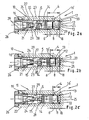
- Fig. 1 is a cross section through a designed as a double-vane vane pump 11 pump 2 is shown. Transverse to a shaft axis 22 of the vane pump 11 extends over approximately the entire width of a housing 23 of the vane pump 11 designed as a flow control valve 10 valve 1.
- the housing 23 is provided for this purpose with a valve bore 15 in which a control piston 14 with an extension 24 is arranged axially displaceable.
- the valve bore 15 is closed on one side by a housing wall 25 and provided at its opposite end with a valve screw 26 to which a consumer, such as a steering gear is connectable.
- a pressure channel not shown, via which flows generated by the vane pump 11, pressurized fluid 29 flows into the valve bore 15.
- the housing 23 has a throttle channel 30, which fluidly connects the pressure chamber 27 with a control chamber 17 on the back 32 of the control piston 14 via a pressure equalization bore 16 (throttle bore) of the pressure chamber 27 and a pressure equalization bore 16 'of the control chamber 17.
- the control piston 14 is acted upon by a spring 3 designed as a compression coil spring 33 on an axial section 13 designed as a guide pin 12.
- the spring 3 is supported on the housing wall 25 and on the guide pin 12 of the control piston 14, wherein the spring force 5 causes the pressure compensating surface 28 of the control piston 14 in the idle state of the flow control valve 10 closes the throttle opening 21 in the valve screw 26.
- the applied pressure in the control chamber 17 between the control piston 14 and the housing wall 25 causes a force rectified to the spring force 5, which counteracts the prevailing pressure in the pressure chamber 27, wherein due to the geometric conditions in the flow control valve, the throttle opening 21 from a certain Pressure of the fluid 29 flowing into the valve bore opens.
- the control piston thus forms a pressure compensator.
- the throttle opening 21 which is penetrated by the extension 24 with a specific cross-sectional sequence, but limited at high flow rates through the throttle opening with a progressive spring force curve and thus not linearly increasing back pressure on the pressure compensator surface 28 and the extension 24
- a spring equipped in a known manner with at least two length ranges 6, 8 with different spring constants 7, 9 is used.
- the second length region 8 of the spring 3, which in the in the FIGS. 1 to 3 embodiment shown has the same outer diameter as the first length range, comes in the radial direction adjacent to the pressure compensating bore 16 'of the control chamber 17 to lie.
- the second length region 8 is adjoined by a third longitudinal region 18 of the spring 3 with the same spring constant 7 as the first longitudinal region 6.
- the number of resilient windings 20 of the third length region 18 is 2.6.
- the spacing of the turns is the same as in the first length range (cf. Fig. 3 ).
- the second length range of the spring 3 changes its axial position to the pressure compensating bore 16 'little.
- the second length region 8 of the spring 3 is compressed. This results in a disproportionate increase in the spring force 5 on the control piston, whereby the pressure in the pressure chamber 27 and thus the pressure in the vane pump is maintained at a high level.
- the degree of filling of the vane pump is thus improved at high flow rates and the characteristic of the vane pump by the inventive use of the spring 3 held linearly.
- Fig. 2 shows, the length 4 of the spring 3 in a position of the control piston 14 in which the pressure compensator - surface 28 abuts against the throttle opening 21 of the valve screw 26 - an investment position - about 25.5 mm.
- the spring force 5 is in this position about 29 N (see. Fig. 4 ).
- the length 4 of the spring 3 is about 17.5 mm and the spring force 5 is about 45 N.
- the spring has a wire diameter of 1.5 mm and a coil diameter of about 15 mm.
- the largest mandrel diameter D d is 13 mm and the smallest sleeve diameter D h is about 17 mm.
- valve 26 valve screw 2 pump 27 pressure chamber 3 feather 28 Pressure balance area 4 length 29 fluid 5 force 30 throttle channel 6 Length range, first 31 7 Spring constant, first 32 Backside v. 14 8th Length range, second 33 Compression coil spring 9 Spring constant, second 34 10 Flow control valve 35 11 Vane pump 36 12 guide pin 37 13 Section, axial v. 14 38 14 spool 39 15 valve bore 40 16.16 ' Pressure compensating bore 41 17 control chamber 42 18 Length range, third 43 19 44 20 Swirl, springy 45 21 throttle opening 46 22 shaft axis 47 23 casing 48 24 extension 49 25 housing wall 50 D Wire diameter D d Spine diameter, largest D h Sleeve diameter, smallest
Landscapes
- Engineering & Computer Science (AREA)
- Physics & Mathematics (AREA)
- Fluid Mechanics (AREA)
- Mechanical Engineering (AREA)
- General Engineering & Computer Science (AREA)
- Details And Applications Of Rotary Liquid Pumps (AREA)
- Rotary Pumps (AREA)
- Safety Valves (AREA)
Claims (13)
- Soupape pour une pompe (2), avec un ressort (3) dont la longueur (4) varie de manière non proportionnelle en fonction de la force (5) agissant sur le ressort (3), le ressort (3) présentant au moins une première région longitudinale (6) avec une première constante de ressort (7) et une deuxième région longitudinale (8) avec une deuxième constante de ressort (9), la première constante de ressort (7) étant inférieure à la deuxième constante de ressort (9), caractérisée en ce que la soupape (1) est une soupape de régulation de débit (10) d'une pompe à cellules à ailettes (11) et le ressort (3) s'applique avec sa première région longitudinale (6) contre une portion axiale (13) d'un piston de commande (14), réalisée sous forme de mandrin de guidage (12), dans un alésage de soupape (15) de la soupape de régulation de débit (10), et la deuxième région longitudinale (8) du ressort (3) est disposée, dans la direction radiale d'un alésage d'équilibrage de la pression (16') d'une chambre de régulation (17), dans l'alésage de soupape (15), en protégeant l'alésage d'équilibrage de pression.
- Soupape selon la revendication 1, caractérisée en ce que la première région longitudinale (6) du ressort (3) est placée autour du mandrin de guidage (12).
- Soupape selon l'une quelconque des revendications 1 ou 2, caractérisée en ce que le ressort (3) présente une troisième région longitudinale (18) avec une autre constante de ressort que celle de la deuxième région longitudinale (8).
- Soupape selon la revendication 3, caractérisée en ce que la troisième région longitudinale (18) du ressort (3) présente la même constante de ressort (7) que la première région longitudinale (6) du ressort (3).
- Soupape selon l'une quelconque des revendications 1 à 4, caractérisée en ce que le ressort (3) présente sept enroulements élastiques (20).
- Soupape selon l'une quelconque des revendications 1 à 5, caractérisée en ce que le nombre des enroulements élastiques (20) de la première région longitudinale (6) est de 2,6, le nombre des enroulements élastiques (20) de la deuxième région longitudinale (8) est de 1,8, et le nombre des enroulements élastiques (20) de la troisième région longitudinale (18) est de 2,6.
- Soupape selon l'une quelconque des revendications 1 à 6, caractérisée en ce que la longueur (4) du ressort (3) dans la position d'appui du piston de commande (14) au niveau d'une ouverture d'étranglement (21) de la soupape de régulation de débit (10) est d'environ 25,5 mm.
- Soupape selon l'une quelconque des revendications 1 à 7, caractérisée en ce que la longueur (4) du ressort (3) dans la position de blocage du piston de commande (14) est d'environ 13,5 mm.
- Soupape selon l'une quelconque des revendications 1 à 8, caractérisée en ce que la force maximale de ressort du ressort (3) est d'environ 68 N.
- Soupape selon l'une quelconque des revendications 1 à 9, caractérisée en ce que la force de ressort du ressort (3) dans la position d'ouverture de la soupape de régulation de débit (10) est d'environ 35 N.
- Soupape selon l'une quelconque des revendications 1 à 10, caractérisée en ce que la première constante de ressort (7) vaut environ 2,0 N/mm.
- Soupape selon l'une quelconque des revendications 1 à 11, caractérisée en ce que la deuxième constante de ressort (9) vaut environ 5,7 N/mm.
- Soupape selon l'une quelconque des revendications 1 à 12, caractérisée en ce que le nombre des enroulements élastiques (20) de la première région longitudinale (6) du ressort (3) est de 5,2, et le nombre des enroulements élastiques (20) de la deuxième région longitudinale (8) du ressort (3) est de 1,8, et la première région longitudinale (6) entoure le mandrin de guidage (12).
Applications Claiming Priority (3)
| Application Number | Priority Date | Filing Date | Title |
|---|---|---|---|
| DE10233579 | 2002-07-24 | ||
| DE2002133579 DE10233579A1 (de) | 2002-07-24 | 2002-07-24 | Ventil für eine Pumpe |
| PCT/EP2003/006091 WO2004015271A1 (fr) | 2002-07-24 | 2003-06-11 | Soupape de regulation de debit non proportionnelle pour pompe a cellules en ailettes |
Publications (2)
| Publication Number | Publication Date |
|---|---|
| EP1523623A1 EP1523623A1 (fr) | 2005-04-20 |
| EP1523623B1 true EP1523623B1 (fr) | 2008-03-19 |
Family
ID=30010333
Family Applications (1)
| Application Number | Title | Priority Date | Filing Date |
|---|---|---|---|
| EP03735598A Expired - Lifetime EP1523623B1 (fr) | 2002-07-24 | 2003-06-11 | Soupape de regulation de debit non proportionnelle pour pompe a cellules en ailettes |
Country Status (4)
| Country | Link |
|---|---|
| EP (1) | EP1523623B1 (fr) |
| DE (2) | DE10233579A1 (fr) |
| ES (1) | ES2301804T3 (fr) |
| WO (1) | WO2004015271A1 (fr) |
Family Cites Families (4)
| Publication number | Priority date | Publication date | Assignee | Title |
|---|---|---|---|---|
| DE4126217A1 (de) * | 1991-08-08 | 1993-02-11 | Zahnradfabrik Friedrichshafen | Regeleinrichtung fuer verdraengerpumpen |
| DE19915555A1 (de) * | 1999-04-07 | 2000-10-12 | Zahnradfabrik Friedrichshafen | Verdrängerpumpe |
| DE19948446A1 (de) * | 1999-10-08 | 2001-04-12 | Continental Teves Ag & Co Ohg | Progressive Saugventilfeder, insbesondere für Pumpen eines geregelten Bremssystems |
| DE10006140A1 (de) * | 2000-02-11 | 2001-08-16 | Zf Lenksysteme Gmbh | Regeleinrichtung für Verdrängerpumpen |
-
2002
- 2002-07-24 DE DE2002133579 patent/DE10233579A1/de not_active Withdrawn
-
2003
- 2003-06-11 EP EP03735598A patent/EP1523623B1/fr not_active Expired - Lifetime
- 2003-06-11 WO PCT/EP2003/006091 patent/WO2004015271A1/fr not_active Ceased
- 2003-06-11 ES ES03735598T patent/ES2301804T3/es not_active Expired - Lifetime
- 2003-06-11 DE DE50309423T patent/DE50309423D1/de not_active Expired - Lifetime
Also Published As
| Publication number | Publication date |
|---|---|
| ES2301804T3 (es) | 2008-07-01 |
| DE10233579A1 (de) | 2004-02-05 |
| DE50309423D1 (de) | 2008-04-30 |
| WO2004015271A1 (fr) | 2004-02-19 |
| EP1523623A1 (fr) | 2005-04-20 |
Similar Documents
| Publication | Publication Date | Title |
|---|---|---|
| EP1987278B1 (fr) | Soupape pre-asservie de limitation de la pression | |
| DE102004012831B4 (de) | Entkoppeltes Rückschlag-Druckbegrenzungsventil | |
| DE69217946T2 (de) | Rückführventil | |
| EP2068057A2 (fr) | Soupape à tiroir à piston | |
| DE2608791C2 (fr) | ||
| DE20321276U1 (de) | Steuerbares Magnetventil | |
| DE2949922C2 (de) | Vorgesteuertes Druckminderventil | |
| AT410696B (de) | Ventilantrieb für ein ventil eines verbrennungsmotors | |
| EP1984629A1 (fr) | Systeme de commande hydraulique a regeneration et soupape de frein d'abaissement | |
| DE102018208352A1 (de) | Hydraulische Spülventilanordnung | |
| DE3840013A1 (de) | Ventil, insbesondere sicherheitsventil | |
| DE69418171T2 (de) | Ventil | |
| DE3502518A1 (de) | Direkt gesteuertes druckbegrenzungsventil | |
| DE102006020528B4 (de) | Ventilanordnung | |
| EP1523623B1 (fr) | Soupape de regulation de debit non proportionnelle pour pompe a cellules en ailettes | |
| DE19956929B4 (de) | Öldruck-Regelventil | |
| EP3118497B1 (fr) | Distributeur hydraulique | |
| EP0943057A1 (fr) | Distributeur pour la commande, independante de la charge, d'un consommateur hydraulique au niveau du sens et de la vitesse | |
| DE4317880A1 (de) | Ventilanordnung | |
| EP1452744B1 (fr) | Dispositif de contrôle hydraulique | |
| WO1990012232A1 (fr) | Soupape pour milieux sous pression | |
| WO2004036329A2 (fr) | Soupape de regulation de pression | |
| DE4221697C2 (de) | Durchflußmengenregelventileinheit | |
| DE102010039657B4 (de) | Bypassventil zur Regulierung eines Fluidflusses, zum Beispiel in einer Konstantpumpe | |
| DE4412459C2 (de) | Ventilanordnung |
Legal Events
| Date | Code | Title | Description |
|---|---|---|---|
| PUAI | Public reference made under article 153(3) epc to a published international application that has entered the european phase |
Free format text: ORIGINAL CODE: 0009012 |
|
| 17P | Request for examination filed |
Effective date: 20050205 |
|
| AK | Designated contracting states |
Kind code of ref document: A1 Designated state(s): AT BE BG CH CY CZ DE DK EE ES FI FR GB GR HU IE IT LI LU MC NL PT RO SE SI SK TR |
|
| RBV | Designated contracting states (corrected) |
Designated state(s): DE ES FR GB |
|
| GRAP | Despatch of communication of intention to grant a patent |
Free format text: ORIGINAL CODE: EPIDOSNIGR1 |
|
| RIC1 | Information provided on ipc code assigned before grant |
Ipc: F04C 14/26 20060101AFI20071130BHEP |
|
| GRAS | Grant fee paid |
Free format text: ORIGINAL CODE: EPIDOSNIGR3 |
|
| GRAA | (expected) grant |
Free format text: ORIGINAL CODE: 0009210 |
|
| AK | Designated contracting states |
Kind code of ref document: B1 Designated state(s): DE ES FR GB |
|
| REG | Reference to a national code |
Ref country code: GB Ref legal event code: FG4D Free format text: NOT ENGLISH |
|
| REF | Corresponds to: |
Ref document number: 50309423 Country of ref document: DE Date of ref document: 20080430 Kind code of ref document: P |
|
| REG | Reference to a national code |
Ref country code: ES Ref legal event code: FG2A Ref document number: 2301804 Country of ref document: ES Kind code of ref document: T3 |
|
| EN | Fr: translation not filed | ||
| PLBE | No opposition filed within time limit |
Free format text: ORIGINAL CODE: 0009261 |
|
| STAA | Information on the status of an ep patent application or granted ep patent |
Free format text: STATUS: NO OPPOSITION FILED WITHIN TIME LIMIT |
|
| 26N | No opposition filed |
Effective date: 20081222 |
|
| GBPC | Gb: european patent ceased through non-payment of renewal fee |
Effective date: 20080619 |
|
| PG25 | Lapsed in a contracting state [announced via postgrant information from national office to epo] |
Ref country code: GB Free format text: LAPSE BECAUSE OF NON-PAYMENT OF DUE FEES Effective date: 20080619 |
|
| PG25 | Lapsed in a contracting state [announced via postgrant information from national office to epo] |
Ref country code: FR Free format text: LAPSE BECAUSE OF FAILURE TO SUBMIT A TRANSLATION OF THE DESCRIPTION OR TO PAY THE FEE WITHIN THE PRESCRIBED TIME-LIMIT Effective date: 20090109 |
|
| PGFP | Annual fee paid to national office [announced via postgrant information from national office to epo] |
Ref country code: ES Payment date: 20120726 Year of fee payment: 10 |
|
| REG | Reference to a national code |
Ref country code: ES Ref legal event code: FD2A Effective date: 20140709 |
|
| PG25 | Lapsed in a contracting state [announced via postgrant information from national office to epo] |
Ref country code: ES Free format text: LAPSE BECAUSE OF NON-PAYMENT OF DUE FEES Effective date: 20130612 |
|
| REG | Reference to a national code |
Ref country code: DE Ref legal event code: R081 Ref document number: 50309423 Country of ref document: DE Owner name: ROBERT BOSCH AUTOMOTIVE STEERING GMBH, DE Free format text: FORMER OWNER: ZF LENKSYSTEME GMBH, 73527 SCHWAEBISCH GMUEND, DE Effective date: 20150423 |
|
| REG | Reference to a national code |
Ref country code: DE Ref legal event code: R081 Ref document number: 50309423 Country of ref document: DE Owner name: ROBERT BOSCH GMBH, DE Free format text: FORMER OWNER: ROBERT BOSCH AUTOMOTIVE STEERING GMBH, 73527 SCHWAEBISCH GMUEND, DE |
|
| PGFP | Annual fee paid to national office [announced via postgrant information from national office to epo] |
Ref country code: DE Payment date: 20200824 Year of fee payment: 18 |
|
| REG | Reference to a national code |
Ref country code: DE Ref legal event code: R119 Ref document number: 50309423 Country of ref document: DE |
|
| PG25 | Lapsed in a contracting state [announced via postgrant information from national office to epo] |
Ref country code: DE Free format text: LAPSE BECAUSE OF NON-PAYMENT OF DUE FEES Effective date: 20220101 |