EP1523291B1 - Trousse pour arthroplastie avec interposition - Google Patents
Trousse pour arthroplastie avec interposition Download PDFInfo
- Publication number
- EP1523291B1 EP1523291B1 EP03764417A EP03764417A EP1523291B1 EP 1523291 B1 EP1523291 B1 EP 1523291B1 EP 03764417 A EP03764417 A EP 03764417A EP 03764417 A EP03764417 A EP 03764417A EP 1523291 B1 EP1523291 B1 EP 1523291B1
- Authority
- EP
- European Patent Office
- Prior art keywords
- implant
- tibial
- joint
- posterior
- anterior
- Prior art date
- Legal status (The legal status is an assumption and is not a legal conclusion. Google has not performed a legal analysis and makes no representation as to the accuracy of the status listed.)
- Expired - Lifetime
Links
Images


Classifications
-
- A—HUMAN NECESSITIES
- A61—MEDICAL OR VETERINARY SCIENCE; HYGIENE
- A61F—FILTERS IMPLANTABLE INTO BLOOD VESSELS; PROSTHESES; DEVICES PROVIDING PATENCY TO, OR PREVENTING COLLAPSING OF, TUBULAR STRUCTURES OF THE BODY, e.g. STENTS; ORTHOPAEDIC, NURSING OR CONTRACEPTIVE DEVICES; FOMENTATION; TREATMENT OR PROTECTION OF EYES OR EARS; BANDAGES, DRESSINGS OR ABSORBENT PADS; FIRST-AID KITS
- A61F2/00—Filters implantable into blood vessels; Prostheses, i.e. artificial substitutes or replacements for parts of the body; Appliances for connecting them with the body; Devices providing patency to, or preventing collapsing of, tubular structures of the body, e.g. stents
- A61F2/02—Prostheses implantable into the body
- A61F2/30—Joints
- A61F2/46—Special tools or methods for implanting or extracting artificial joints, accessories, bone grafts or substitutes, or particular adaptations therefor
- A61F2/4657—Measuring instruments used for implanting artificial joints
-
- A—HUMAN NECESSITIES
- A61—MEDICAL OR VETERINARY SCIENCE; HYGIENE
- A61B—DIAGNOSIS; SURGERY; IDENTIFICATION
- A61B17/00—Surgical instruments, devices or methods, e.g. tourniquets
- A61B17/16—Bone cutting, breaking or removal means other than saws, e.g. Osteoclasts; Drills or chisels for bones; Trepans
- A61B17/1659—Surgical rasps, files, planes, or scrapers
-
- A—HUMAN NECESSITIES
- A61—MEDICAL OR VETERINARY SCIENCE; HYGIENE
- A61B—DIAGNOSIS; SURGERY; IDENTIFICATION
- A61B17/00—Surgical instruments, devices or methods, e.g. tourniquets
- A61B17/16—Bone cutting, breaking or removal means other than saws, e.g. Osteoclasts; Drills or chisels for bones; Trepans
- A61B17/1662—Bone cutting, breaking or removal means other than saws, e.g. Osteoclasts; Drills or chisels for bones; Trepans for particular parts of the body
- A61B17/1675—Bone cutting, breaking or removal means other than saws, e.g. Osteoclasts; Drills or chisels for bones; Trepans for particular parts of the body for the knee
-
- A—HUMAN NECESSITIES
- A61—MEDICAL OR VETERINARY SCIENCE; HYGIENE
- A61B—DIAGNOSIS; SURGERY; IDENTIFICATION
- A61B90/00—Instruments, implements or accessories specially adapted for surgery or diagnosis and not covered by any of the groups A61B1/00 - A61B50/00, e.g. for luxation treatment or for protecting wound edges
- A61B90/06—Measuring instruments not otherwise provided for
-
- A—HUMAN NECESSITIES
- A61—MEDICAL OR VETERINARY SCIENCE; HYGIENE
- A61F—FILTERS IMPLANTABLE INTO BLOOD VESSELS; PROSTHESES; DEVICES PROVIDING PATENCY TO, OR PREVENTING COLLAPSING OF, TUBULAR STRUCTURES OF THE BODY, e.g. STENTS; ORTHOPAEDIC, NURSING OR CONTRACEPTIVE DEVICES; FOMENTATION; TREATMENT OR PROTECTION OF EYES OR EARS; BANDAGES, DRESSINGS OR ABSORBENT PADS; FIRST-AID KITS
- A61F2/00—Filters implantable into blood vessels; Prostheses, i.e. artificial substitutes or replacements for parts of the body; Appliances for connecting them with the body; Devices providing patency to, or preventing collapsing of, tubular structures of the body, e.g. stents
- A61F2/02—Prostheses implantable into the body
- A61F2/30—Joints
- A61F2/30721—Accessories
-
- A—HUMAN NECESSITIES
- A61—MEDICAL OR VETERINARY SCIENCE; HYGIENE
- A61F—FILTERS IMPLANTABLE INTO BLOOD VESSELS; PROSTHESES; DEVICES PROVIDING PATENCY TO, OR PREVENTING COLLAPSING OF, TUBULAR STRUCTURES OF THE BODY, e.g. STENTS; ORTHOPAEDIC, NURSING OR CONTRACEPTIVE DEVICES; FOMENTATION; TREATMENT OR PROTECTION OF EYES OR EARS; BANDAGES, DRESSINGS OR ABSORBENT PADS; FIRST-AID KITS
- A61F2/00—Filters implantable into blood vessels; Prostheses, i.e. artificial substitutes or replacements for parts of the body; Appliances for connecting them with the body; Devices providing patency to, or preventing collapsing of, tubular structures of the body, e.g. stents
- A61F2/02—Prostheses implantable into the body
- A61F2/30—Joints
- A61F2/38—Joints for elbows or knees
- A61F2/3872—Meniscus for implantation between the natural bone surfaces
-
- A—HUMAN NECESSITIES
- A61—MEDICAL OR VETERINARY SCIENCE; HYGIENE
- A61B—DIAGNOSIS; SURGERY; IDENTIFICATION
- A61B17/00—Surgical instruments, devices or methods, e.g. tourniquets
- A61B17/00234—Surgical instruments, devices or methods, e.g. tourniquets for minimally invasive surgery
-
- A—HUMAN NECESSITIES
- A61—MEDICAL OR VETERINARY SCIENCE; HYGIENE
- A61B—DIAGNOSIS; SURGERY; IDENTIFICATION
- A61B17/00—Surgical instruments, devices or methods, e.g. tourniquets
- A61B17/56—Surgical instruments or methods for treatment of bones or joints; Devices specially adapted therefor
- A61B17/58—Surgical instruments or methods for treatment of bones or joints; Devices specially adapted therefor for osteosynthesis, e.g. bone plates, screws, setting implements or the like
- A61B17/68—Internal fixation devices, including fasteners and spinal fixators, even if a part thereof projects from the skin
- A61B17/70—Spinal positioners or stabilisers ; Bone stabilisers comprising fluid filler in an implant
-
- A—HUMAN NECESSITIES
- A61—MEDICAL OR VETERINARY SCIENCE; HYGIENE
- A61B—DIAGNOSIS; SURGERY; IDENTIFICATION
- A61B17/00—Surgical instruments, devices or methods, e.g. tourniquets
- A61B2017/00535—Surgical instruments, devices or methods, e.g. tourniquets pneumatically or hydraulically operated
- A61B2017/00557—Surgical instruments, devices or methods, e.g. tourniquets pneumatically or hydraulically operated inflatable
-
- A—HUMAN NECESSITIES
- A61—MEDICAL OR VETERINARY SCIENCE; HYGIENE
- A61B—DIAGNOSIS; SURGERY; IDENTIFICATION
- A61B90/00—Instruments, implements or accessories specially adapted for surgery or diagnosis and not covered by any of the groups A61B1/00 - A61B50/00, e.g. for luxation treatment or for protecting wound edges
- A61B90/06—Measuring instruments not otherwise provided for
- A61B2090/061—Measuring instruments not otherwise provided for for measuring dimensions, e.g. length
-
- A—HUMAN NECESSITIES
- A61—MEDICAL OR VETERINARY SCIENCE; HYGIENE
- A61F—FILTERS IMPLANTABLE INTO BLOOD VESSELS; PROSTHESES; DEVICES PROVIDING PATENCY TO, OR PREVENTING COLLAPSING OF, TUBULAR STRUCTURES OF THE BODY, e.g. STENTS; ORTHOPAEDIC, NURSING OR CONTRACEPTIVE DEVICES; FOMENTATION; TREATMENT OR PROTECTION OF EYES OR EARS; BANDAGES, DRESSINGS OR ABSORBENT PADS; FIRST-AID KITS
- A61F2/00—Filters implantable into blood vessels; Prostheses, i.e. artificial substitutes or replacements for parts of the body; Appliances for connecting them with the body; Devices providing patency to, or preventing collapsing of, tubular structures of the body, e.g. stents
- A61F2/02—Prostheses implantable into the body
- A61F2/30—Joints
- A61F2/46—Special tools or methods for implanting or extracting artificial joints, accessories, bone grafts or substitutes, or particular adaptations therefor
- A61F2/4603—Special tools or methods for implanting or extracting artificial joints, accessories, bone grafts or substitutes, or particular adaptations therefor for insertion or extraction of endoprosthetic joints or of accessories thereof
-
- A—HUMAN NECESSITIES
- A61—MEDICAL OR VETERINARY SCIENCE; HYGIENE
- A61F—FILTERS IMPLANTABLE INTO BLOOD VESSELS; PROSTHESES; DEVICES PROVIDING PATENCY TO, OR PREVENTING COLLAPSING OF, TUBULAR STRUCTURES OF THE BODY, e.g. STENTS; ORTHOPAEDIC, NURSING OR CONTRACEPTIVE DEVICES; FOMENTATION; TREATMENT OR PROTECTION OF EYES OR EARS; BANDAGES, DRESSINGS OR ABSORBENT PADS; FIRST-AID KITS
- A61F2/00—Filters implantable into blood vessels; Prostheses, i.e. artificial substitutes or replacements for parts of the body; Appliances for connecting them with the body; Devices providing patency to, or preventing collapsing of, tubular structures of the body, e.g. stents
- A61F2/02—Prostheses implantable into the body
- A61F2/30—Joints
- A61F2/46—Special tools or methods for implanting or extracting artificial joints, accessories, bone grafts or substitutes, or particular adaptations therefor
- A61F2/4684—Trial or dummy prostheses
-
- A—HUMAN NECESSITIES
- A61—MEDICAL OR VETERINARY SCIENCE; HYGIENE
- A61F—FILTERS IMPLANTABLE INTO BLOOD VESSELS; PROSTHESES; DEVICES PROVIDING PATENCY TO, OR PREVENTING COLLAPSING OF, TUBULAR STRUCTURES OF THE BODY, e.g. STENTS; ORTHOPAEDIC, NURSING OR CONTRACEPTIVE DEVICES; FOMENTATION; TREATMENT OR PROTECTION OF EYES OR EARS; BANDAGES, DRESSINGS OR ABSORBENT PADS; FIRST-AID KITS
- A61F2/00—Filters implantable into blood vessels; Prostheses, i.e. artificial substitutes or replacements for parts of the body; Appliances for connecting them with the body; Devices providing patency to, or preventing collapsing of, tubular structures of the body, e.g. stents
- A61F2/02—Prostheses implantable into the body
- A61F2/30—Joints
- A61F2002/30001—Additional features of subject-matter classified in A61F2/28, A61F2/30 and subgroups thereof
- A61F2002/30108—Shapes
- A61F2002/3011—Cross-sections or two-dimensional shapes
- A61F2002/30112—Rounded shapes, e.g. with rounded corners
- A61F2002/30133—Rounded shapes, e.g. with rounded corners kidney-shaped or bean-shaped
-
- A—HUMAN NECESSITIES
- A61—MEDICAL OR VETERINARY SCIENCE; HYGIENE
- A61F—FILTERS IMPLANTABLE INTO BLOOD VESSELS; PROSTHESES; DEVICES PROVIDING PATENCY TO, OR PREVENTING COLLAPSING OF, TUBULAR STRUCTURES OF THE BODY, e.g. STENTS; ORTHOPAEDIC, NURSING OR CONTRACEPTIVE DEVICES; FOMENTATION; TREATMENT OR PROTECTION OF EYES OR EARS; BANDAGES, DRESSINGS OR ABSORBENT PADS; FIRST-AID KITS
- A61F2/00—Filters implantable into blood vessels; Prostheses, i.e. artificial substitutes or replacements for parts of the body; Appliances for connecting them with the body; Devices providing patency to, or preventing collapsing of, tubular structures of the body, e.g. stents
- A61F2/02—Prostheses implantable into the body
- A61F2/30—Joints
- A61F2002/30001—Additional features of subject-matter classified in A61F2/28, A61F2/30 and subgroups thereof
- A61F2002/30316—The prosthesis having different structural features at different locations within the same prosthesis; Connections between prosthetic parts; Special structural features of bone or joint prostheses not otherwise provided for
- A61F2002/30535—Special structural features of bone or joint prostheses not otherwise provided for
- A61F2002/30604—Special structural features of bone or joint prostheses not otherwise provided for modular
- A61F2002/30616—Sets comprising a plurality of prosthetic parts of different sizes or orientations
-
- A—HUMAN NECESSITIES
- A61—MEDICAL OR VETERINARY SCIENCE; HYGIENE
- A61F—FILTERS IMPLANTABLE INTO BLOOD VESSELS; PROSTHESES; DEVICES PROVIDING PATENCY TO, OR PREVENTING COLLAPSING OF, TUBULAR STRUCTURES OF THE BODY, e.g. STENTS; ORTHOPAEDIC, NURSING OR CONTRACEPTIVE DEVICES; FOMENTATION; TREATMENT OR PROTECTION OF EYES OR EARS; BANDAGES, DRESSINGS OR ABSORBENT PADS; FIRST-AID KITS
- A61F2/00—Filters implantable into blood vessels; Prostheses, i.e. artificial substitutes or replacements for parts of the body; Appliances for connecting them with the body; Devices providing patency to, or preventing collapsing of, tubular structures of the body, e.g. stents
- A61F2/02—Prostheses implantable into the body
- A61F2/30—Joints
- A61F2002/30001—Additional features of subject-matter classified in A61F2/28, A61F2/30 and subgroups thereof
- A61F2002/30667—Features concerning an interaction with the environment or a particular use of the prosthesis
- A61F2002/30708—Means for distinguishing between left-sided and right-sided devices, Sets comprising both left-sided and right-sided prosthetic parts
-
- A—HUMAN NECESSITIES
- A61—MEDICAL OR VETERINARY SCIENCE; HYGIENE
- A61F—FILTERS IMPLANTABLE INTO BLOOD VESSELS; PROSTHESES; DEVICES PROVIDING PATENCY TO, OR PREVENTING COLLAPSING OF, TUBULAR STRUCTURES OF THE BODY, e.g. STENTS; ORTHOPAEDIC, NURSING OR CONTRACEPTIVE DEVICES; FOMENTATION; TREATMENT OR PROTECTION OF EYES OR EARS; BANDAGES, DRESSINGS OR ABSORBENT PADS; FIRST-AID KITS
- A61F2/00—Filters implantable into blood vessels; Prostheses, i.e. artificial substitutes or replacements for parts of the body; Appliances for connecting them with the body; Devices providing patency to, or preventing collapsing of, tubular structures of the body, e.g. stents
- A61F2/02—Prostheses implantable into the body
- A61F2/30—Joints
- A61F2002/30001—Additional features of subject-matter classified in A61F2/28, A61F2/30 and subgroups thereof
- A61F2002/30667—Features concerning an interaction with the environment or a particular use of the prosthesis
- A61F2002/3071—Identification means; Administration of patients
-
- A—HUMAN NECESSITIES
- A61—MEDICAL OR VETERINARY SCIENCE; HYGIENE
- A61F—FILTERS IMPLANTABLE INTO BLOOD VESSELS; PROSTHESES; DEVICES PROVIDING PATENCY TO, OR PREVENTING COLLAPSING OF, TUBULAR STRUCTURES OF THE BODY, e.g. STENTS; ORTHOPAEDIC, NURSING OR CONTRACEPTIVE DEVICES; FOMENTATION; TREATMENT OR PROTECTION OF EYES OR EARS; BANDAGES, DRESSINGS OR ABSORBENT PADS; FIRST-AID KITS
- A61F2/00—Filters implantable into blood vessels; Prostheses, i.e. artificial substitutes or replacements for parts of the body; Appliances for connecting them with the body; Devices providing patency to, or preventing collapsing of, tubular structures of the body, e.g. stents
- A61F2/02—Prostheses implantable into the body
- A61F2/30—Joints
- A61F2/30721—Accessories
- A61F2002/30754—Implants for interposition between two natural articular surfaces
-
- A—HUMAN NECESSITIES
- A61—MEDICAL OR VETERINARY SCIENCE; HYGIENE
- A61F—FILTERS IMPLANTABLE INTO BLOOD VESSELS; PROSTHESES; DEVICES PROVIDING PATENCY TO, OR PREVENTING COLLAPSING OF, TUBULAR STRUCTURES OF THE BODY, e.g. STENTS; ORTHOPAEDIC, NURSING OR CONTRACEPTIVE DEVICES; FOMENTATION; TREATMENT OR PROTECTION OF EYES OR EARS; BANDAGES, DRESSINGS OR ABSORBENT PADS; FIRST-AID KITS
- A61F2/00—Filters implantable into blood vessels; Prostheses, i.e. artificial substitutes or replacements for parts of the body; Appliances for connecting them with the body; Devices providing patency to, or preventing collapsing of, tubular structures of the body, e.g. stents
- A61F2/02—Prostheses implantable into the body
- A61F2/30—Joints
- A61F2/38—Joints for elbows or knees
- A61F2002/3895—Joints for elbows or knees unicompartimental
-
- A—HUMAN NECESSITIES
- A61—MEDICAL OR VETERINARY SCIENCE; HYGIENE
- A61F—FILTERS IMPLANTABLE INTO BLOOD VESSELS; PROSTHESES; DEVICES PROVIDING PATENCY TO, OR PREVENTING COLLAPSING OF, TUBULAR STRUCTURES OF THE BODY, e.g. STENTS; ORTHOPAEDIC, NURSING OR CONTRACEPTIVE DEVICES; FOMENTATION; TREATMENT OR PROTECTION OF EYES OR EARS; BANDAGES, DRESSINGS OR ABSORBENT PADS; FIRST-AID KITS
- A61F2/00—Filters implantable into blood vessels; Prostheses, i.e. artificial substitutes or replacements for parts of the body; Appliances for connecting them with the body; Devices providing patency to, or preventing collapsing of, tubular structures of the body, e.g. stents
- A61F2/02—Prostheses implantable into the body
- A61F2/30—Joints
- A61F2/46—Special tools or methods for implanting or extracting artificial joints, accessories, bone grafts or substitutes, or particular adaptations therefor
- A61F2002/4635—Special tools or methods for implanting or extracting artificial joints, accessories, bone grafts or substitutes, or particular adaptations therefor using minimally invasive surgery
-
- A—HUMAN NECESSITIES
- A61—MEDICAL OR VETERINARY SCIENCE; HYGIENE
- A61F—FILTERS IMPLANTABLE INTO BLOOD VESSELS; PROSTHESES; DEVICES PROVIDING PATENCY TO, OR PREVENTING COLLAPSING OF, TUBULAR STRUCTURES OF THE BODY, e.g. STENTS; ORTHOPAEDIC, NURSING OR CONTRACEPTIVE DEVICES; FOMENTATION; TREATMENT OR PROTECTION OF EYES OR EARS; BANDAGES, DRESSINGS OR ABSORBENT PADS; FIRST-AID KITS
- A61F2/00—Filters implantable into blood vessels; Prostheses, i.e. artificial substitutes or replacements for parts of the body; Appliances for connecting them with the body; Devices providing patency to, or preventing collapsing of, tubular structures of the body, e.g. stents
- A61F2/02—Prostheses implantable into the body
- A61F2/30—Joints
- A61F2/46—Special tools or methods for implanting or extracting artificial joints, accessories, bone grafts or substitutes, or particular adaptations therefor
- A61F2/4657—Measuring instruments used for implanting artificial joints
- A61F2002/4658—Measuring instruments used for implanting artificial joints for measuring dimensions, e.g. length
- A61F2002/4661—Measuring instruments used for implanting artificial joints for measuring dimensions, e.g. length for measuring thickness
-
- A—HUMAN NECESSITIES
- A61—MEDICAL OR VETERINARY SCIENCE; HYGIENE
- A61F—FILTERS IMPLANTABLE INTO BLOOD VESSELS; PROSTHESES; DEVICES PROVIDING PATENCY TO, OR PREVENTING COLLAPSING OF, TUBULAR STRUCTURES OF THE BODY, e.g. STENTS; ORTHOPAEDIC, NURSING OR CONTRACEPTIVE DEVICES; FOMENTATION; TREATMENT OR PROTECTION OF EYES OR EARS; BANDAGES, DRESSINGS OR ABSORBENT PADS; FIRST-AID KITS
- A61F2/00—Filters implantable into blood vessels; Prostheses, i.e. artificial substitutes or replacements for parts of the body; Appliances for connecting them with the body; Devices providing patency to, or preventing collapsing of, tubular structures of the body, e.g. stents
- A61F2/02—Prostheses implantable into the body
- A61F2/30—Joints
- A61F2/46—Special tools or methods for implanting or extracting artificial joints, accessories, bone grafts or substitutes, or particular adaptations therefor
- A61F2/4657—Measuring instruments used for implanting artificial joints
- A61F2002/4662—Measuring instruments used for implanting artificial joints for measuring penetration depth
-
- A—HUMAN NECESSITIES
- A61—MEDICAL OR VETERINARY SCIENCE; HYGIENE
- A61F—FILTERS IMPLANTABLE INTO BLOOD VESSELS; PROSTHESES; DEVICES PROVIDING PATENCY TO, OR PREVENTING COLLAPSING OF, TUBULAR STRUCTURES OF THE BODY, e.g. STENTS; ORTHOPAEDIC, NURSING OR CONTRACEPTIVE DEVICES; FOMENTATION; TREATMENT OR PROTECTION OF EYES OR EARS; BANDAGES, DRESSINGS OR ABSORBENT PADS; FIRST-AID KITS
- A61F2230/00—Geometry of prostheses classified in groups A61F2/00 - A61F2/26 or A61F2/82 or A61F9/00 or A61F11/00 or subgroups thereof
- A61F2230/0002—Two-dimensional shapes, e.g. cross-sections
- A61F2230/0004—Rounded shapes, e.g. with rounded corners
- A61F2230/0015—Kidney-shaped, e.g. bean-shaped
-
- A—HUMAN NECESSITIES
- A61—MEDICAL OR VETERINARY SCIENCE; HYGIENE
- A61F—FILTERS IMPLANTABLE INTO BLOOD VESSELS; PROSTHESES; DEVICES PROVIDING PATENCY TO, OR PREVENTING COLLAPSING OF, TUBULAR STRUCTURES OF THE BODY, e.g. STENTS; ORTHOPAEDIC, NURSING OR CONTRACEPTIVE DEVICES; FOMENTATION; TREATMENT OR PROTECTION OF EYES OR EARS; BANDAGES, DRESSINGS OR ABSORBENT PADS; FIRST-AID KITS
- A61F2250/00—Special features of prostheses classified in groups A61F2/00 - A61F2/26 or A61F2/82 or A61F9/00 or A61F11/00 or subgroups thereof
- A61F2250/0058—Additional features; Implant or prostheses properties not otherwise provided for
- A61F2250/0084—Means for distinguishing between left-sided and right-sided devices; Sets comprising both left-sided and right-sided prosthetic parts
-
- A—HUMAN NECESSITIES
- A61—MEDICAL OR VETERINARY SCIENCE; HYGIENE
- A61F—FILTERS IMPLANTABLE INTO BLOOD VESSELS; PROSTHESES; DEVICES PROVIDING PATENCY TO, OR PREVENTING COLLAPSING OF, TUBULAR STRUCTURES OF THE BODY, e.g. STENTS; ORTHOPAEDIC, NURSING OR CONTRACEPTIVE DEVICES; FOMENTATION; TREATMENT OR PROTECTION OF EYES OR EARS; BANDAGES, DRESSINGS OR ABSORBENT PADS; FIRST-AID KITS
- A61F2250/00—Special features of prostheses classified in groups A61F2/00 - A61F2/26 or A61F2/82 or A61F9/00 or A61F11/00 or subgroups thereof
- A61F2250/0058—Additional features; Implant or prostheses properties not otherwise provided for
- A61F2250/0085—Identification means; Administration of patients
- A61F2250/0087—Identification means; Administration of patients colour-coded
-
- A—HUMAN NECESSITIES
- A61—MEDICAL OR VETERINARY SCIENCE; HYGIENE
- A61F—FILTERS IMPLANTABLE INTO BLOOD VESSELS; PROSTHESES; DEVICES PROVIDING PATENCY TO, OR PREVENTING COLLAPSING OF, TUBULAR STRUCTURES OF THE BODY, e.g. STENTS; ORTHOPAEDIC, NURSING OR CONTRACEPTIVE DEVICES; FOMENTATION; TREATMENT OR PROTECTION OF EYES OR EARS; BANDAGES, DRESSINGS OR ABSORBENT PADS; FIRST-AID KITS
- A61F2250/00—Special features of prostheses classified in groups A61F2/00 - A61F2/26 or A61F2/82 or A61F9/00 or A61F11/00 or subgroups thereof
- A61F2250/0058—Additional features; Implant or prostheses properties not otherwise provided for
- A61F2250/0085—Identification means; Administration of patients
- A61F2250/0089—Identification means; Administration of patients coded with symbols, e.g. dots, numbers, letters, words
Definitions
- kits that include instruments for use in preparing (e.g., smoothing) and/or using (e.g., selecting and implanting) interpositional implants as described herein.
- the closest prior art is WO 0059411A , which discloses an interpositional implant system.
- prosthetic implants formed of biomaterials that can be delivered and finally cured in situ , and/or that can be partially or fully prepared ex vivo , for implantation into the body, e.g., using minimally invasive techniques. See for instance, U.S. Patent Nos. 5,556,429 ; 5,795,353 ; 5,888,220 ; 6,079,868 ; 6,140,452 ; 6,224,630 ; 6,248,131 ; 6,306,177 ; and 6,443,988 , as well as US Application Publication Nos.
- US Patent No. 6,206,927 describes a self-centering meniscal prosthesis device suitable for minimally invasive, surgical implantation into the cavity between a femoral condyle and the corresponding tibial plateau is composed of a hard, high modulus material shaped such that the contour of the device and the natural articulation of the knee exerts a restoring force on the free-floating device.
- Sulzer has introduced a unicompartmental interpositional spacer to treat osteoarthritis in the knee.
- such cutting and shaping devices are used in open surgical procedures, e.g., for the purpose of resecting bone in order to provide partial or total knee replacements.
- open surgical procedures e.g., for the purpose of resecting bone in order to provide partial or total knee replacements.
- Spotorno, et al. US Patent No. 6,319,256 , which describes a bone rasp for a femur head prosthesis.
- Braslow, et al. US Patent No. 6,059,831 , which describes a method of implanting a uni-condylar knee prosthesis, including the steps of preparing the bone surfaces of both the femoral and tibal compartments.
- the femoral compartment is prepared by making a distal cut, a posterior cut, and a posterior chamfer cut.
- the tibial compartment is prepared by using a cutting guide and following the sclerotic bone formation on the proximal tibia. See also, Engh, et al., which describes an apparatus and method for "sculpting" the surface of a joint.
- Surgical orthopedic instruments can also include arthroscopic and other minimally invasive instruments such as reciprocating bone saws, rasps, and the like.
- Shechter et al. (US Patent No. 5,685,840 ) describes a method and apparatus for minimally invasive tissue removal that includes motor driven reciprocating cutting blade, having the ability to control the frequency of reciprocation using an integrated feedback control system, and including optional rasp or tissue morcelator cutting heads.
- Surgical, including minimally invasive, devices have also been described to achieve bone cutting or smoothing using non-mechanical means, as by the use of lasers for instance. See, for instance, " Parameters for Safe Application of the 2.1 ⁇ m Holmium:YAG Laser for Chondroplasty of the Medial Femoral Condyle", Janecki et al., Arthroplasty Arthroscopic Surgery 9(1):1-6, 1998 .
- segmental measurements can be made of various orthopedic dimensions. See, for instance, "Segmental Measures” at http://www.people.virginia.edu/ ⁇ smb4v/growth/segmenta.htm, which describes the manner in which knee height can be used to estimate stature in someone with contractures who is unable to straighten out.
- the subject can be either lying supine on a table or sitting upright.
- the subject's knee and ankle should both be at a ninety degree angles.
- a caliper is used for this measurement. One end of the caliper is placed under the heel of the foot right under the malleolus, and the other blade of the caliper is placed on the anterior surface of the thigh approximately above the head of the fibula.
- tibial length can be measured from the medial joint line of the knee to the distal edge of the medial malleolus.
- the subject should be sitting with the leg to be measured crossed over the other leg.
- the measurer should locate and mark the two important landmarks on the subject.
- the medial epicondyle of the femur should be found and a mark made on the subject's skin at the medial facet of the femorotibial joint space.
- the distal tip of the malleolus should be found and marked.
- the measurer should sit or squat next to the leg to obtain an accurate measurement.
- the arms or blades of the anthropometer are placed on both landmarks, and a measurement is read.
- the shaft of the anthropometer should be parallel to the axis of the leg.
- This measurement can also be taken with a flexible measuring tape in which the zero end is placed on the malleolus landmark and the measurement value is read on the proximal tibial border. The measurement is taken to the nearest 0.1 cm.
- the tibial cutting jig includes a base for sliding reception onto an intramedullary alignment rod preinstalled generally along the longitudinal axis of the tibia.
- the base includes laterally extending outriggers carrying removable measurement keys of selected size for spacing the base above the tibial plateau by a selected dimension.
- An anterior saw guide depends from the base and is thus positioned relative to the tibial plateau in accordance with the sizes of the measurement keys.
- the present invention relates to devices for treating joints that have deteriorated to the "bone on bone" stage.
- Devices are provided for providing some or all of the steps of: a) preparing a joint to receive an implant, b) determining an appropriate implant size for a particular joint, c) determining an appropriate implant thickness, d) inserting the implant into the joint, and/or e) securing the implant within the joint to a desired extent.
- an apparatus in accordance with the present invention is provided for determining an optimal size for an implant to be inserted into the joint.
- the implant is designed to provide a glide path with respect to the femoral condyle.
- Such a device can be used in patients having joints that have progressed to the stage of "bone on bone", and thus provides a replacement for the function of articular cartilage as well as some or all of the meniscus, and particularly at the central weight-bearing area of the medial or lateral tibial plateau, in order to restore alignment, while providing an elastomeric, cushioning function.
- the present implant is more permanently anchored in place, in significant part by one or more posterior projections, such as the posterior lip, as well by the optional but preferred use of anterior fixation means (such as embedded sutures) secured to anterior soft tissue structures.
- a preferred implant in accordance with the present invention provides a unique combination of a femoral glide path and convexity of the tibial surface of the implant, together with a posterior mesial lip.
- the implant provides an indentation adapted to accommodate the tibial spine, which together with a slight feathering of the implant on the underside at the tibial spine, the general kidney shape of the implant, and the convexity of the tibial surface, will permit the implant to be congruent with the concave tibia and the posterior mesial lip that extends over the posterior portion of the tibia and into the mesial side of the tibia into the PCL fossa of the tibia.
- such an implant can be provided in various sizes to accommodate different anterior-posterior dimensions of the tibia and different tibial concavities.
- the amount of convexity of the tibial surface will be varied with the different sizes depending on the amount of actual concavity that there is in the tibia.
- applicant has found that "one size fits all" with respect to tibial concavity. Selection of an optimal size (and optionally also geometry) is facilitated by use of a measuring device of the present invention.
- a kit of the present invention preferably includes a device for measuring one or more dimensions associated with the knee, and has particular use for measuring various aspects associated with the tibial plateau of the medial compartment of the knee in the course of preparing and/or sizing interpositional implants.
- the device is particularly well suited to be used with small incisions (e.g., less than about 7,6 cm (3 inches), and preferably less than about 3,8 cm (11 ⁇ 2 inch)) of the type used to perform arthrotomy procedures involving the knee.
- the invention provides devices for measuring one or more dimensions selected from the group consisting of an anterior-posterior dimension, a medial-lateral dimension, and a height/depth dimension.
- the device can be used to determine a dimension between the anterior and posterior edges of the tibial surface, while also providing a suitable depth measurement of the tibial depression (also referred to herein as "bowl") at a point approximately midway between the raised anterior and posterior edges of the tibial plateau. It is preferred to measure at least the anterior-posterior length, since the medial lateral dimension of preferred implants will typically correspond in a predictable fashion with the anterior-posterior dimension.
- That depth is determined as the distance(s) between the bottommost point of the tibial plateau, and a line drawn between the uppermost anterior and posterior portions of the tibial plateau.
- the device can be calibrated and used in any suitable fashion, e.g., having independent gradations along various axes, or having stable or moveable markings that are unique to and correlate with particular implant selections.
- the present invention includes a device for:
- the measuring device is of sufficient size and proportions to permit it to be inserted (e.g., turned onto its side) into the same small arthrotomy incision through which the implant itself is to be placed.
- the device is sufficiently thin (ruler like) to permit it to be slipped into the arthrotomy incision and between the distracted condylar and tibial surfaces.
- an appropriate final implant can be selected, implanted and secured.
- some or all of the components of this invention can be designed in a manner that eases their selection and use, while serving to minimize error.
- some or all of the components can be number coded, bar coded, shape coded, tactile coded and/or visually (e.g. color) coded).
- An implant in accordance with the present invention can be used in a method that includes first determining the proper implant thickness needed to match physiological values.
- the surgeon prepares the site arthroscopically, removing excess cartilage and removing the medial meniscus to the medial ring, using a portal of about 1cm in order to provide suitable arthroscopic access while maintaining the presence of fluid in the joint.
- the implant can be initially molded ex vivo and include one or more embedded or attached fixation portions (e.g., anterior sutures or tabs), at which time it is inserted into the knee.
- surgeon will then typically feel the implant once in position, to confirm that the implant is properly seated, and will extend the knee to provide varus stress on the lower leg, obtaining congruency as the implant continues to cure by finally molding both surfaces of the implant (to both the tibial surface and condyle, respectively).
- the patient will have a diagnosis of osteoarthritis and have loss of cartilage on the articulating surface.
- a determination will be made of the amount of correction needed for the reestablishment of a normal angle of articulation.
- the ligaments will be balanced so that there is no loss of range of motion with the implant in place. In some applications the horizontal plane of the original articular surface runs through the center of the implant.
- Access to the site is preferably obtained in a minimally invasive way. In a particularly preferred example, this is accomplished through arthroscopic means with arthroscopic portals. In an alternative example, the access is accomplished by a mini arthrotomy with a small incision that allows access to the joint without sacrificing nerves, vessels, muscles or ligaments surrounding the joint. In the preferred embodiment fibrillated articulating cartilage that is degenerated is removed down to the subchondral surface.
- a medial arthrotomy is created to provide access for the implant.
- This also provides an opening to use one or more smoothing devices of the present invention on either the femoral and/or tibial surfaces and completion of the anterior.
- the smoothing device can be, for example, secured to a powered driver (e.g., a Triton brand reciprocating saw) by inserting the shaft of the device and tightening the collett on the driver.
- the speed of the driver can be controlled in two ways, namely, by either limiting the air pressure delivered to the driver using an air regulator, and/or by a variable speed valve on the driver, which provides more speed (strokes per second) with increased depression of the control lever.
- the smoothing device can be manipulated around and within the joint space, usually guided by placing an index finger on the non-cutting side of the blade.
- blade is sufficiently flexible to permit it to be bended by finger pressure alone, without undue fatigue on the part of the surgeon. Ridges and shape points can be removed from the femur, while taking care not to cut through to trabecular bone.
- the relatively non-aggressive cutting surface of the device, relative to conventional rasps and rotating burrs, makes this easier to accomplish. Osteophytes should also be removed if they might impinge on the implant or limit range of motion.
- Smoothness of the femoral and/or tibial surfaces can be judged in any suitable manner, including by finger palpation. When the surfaces are deemed smooth enough, the joint is thoroughly irrigated to remove any debris. Although typically powered, the excursion can be kept within a range sufficient to permit the surgeon's finger to be kept on the opposite (non-smoothing) surface of the blade-like device, in order to gently oscillate with it. This, combined with the desired flexibility of the device permit it to be moved around the joint, assuming different conformations, in order to smooth any particular surface.
- the body of a smoothing tool is adjusted to the anatomy by bending so it can access areas not accessible with a straight rasp or shaver.
- the bend allows the smoother to remove osteophytes from the posterior portion of the condyle, which would not be accessible with a commonly used rasp or shaver.
- the smoother can also be guided into contact with different areas of the bone by flexing and extending the joint. Since the operator need only guide the smoother into position and the motion of the smoother which causes the bone removal is provided by the reciprocating action of the saw, it can easily be used through 1 cm portal as well as a small arthrotomy. Since the abrasive surface is non-aggressive to soft tissue the surgeon can use a gloved indexed finger to direct, enhance and evaluate the smoothing of a bony surface.
- the system involves the preparation and use of one or more components (e.g., polymeric and/or metallic) that can be at least partially formed outside the body, for insertion and placement into the body, and that can optionally then be further formed within the joint site in order to enhance conformance.
- components e.g., polymeric and/or metallic
- the optional ability to finally form one or more components in situ provides various additional benefits, such as increased control over the overall size and shape of the final prosthesis, improved shape and compliance of the surface apposing natural bone, and finally, improved shape and compliance of the opposite, articulating surface.
- the method and system permit the on site preparation or previous manufacture of a unicompartmental interpositional arthroplasty device that comprises a polymeric material such as polyurethane.
- the components of the system are preferably coordinated, e.g., by being similarly designed and/or labeled, in order to facilitate their use and thereby ensure the proper selection and implantation of an implant.
- the implant can be prepared (including full formed and/or cured) ex vivo, for later implantation.
- the present invention therefore provides an implant that is designed to be formed to and congruent with the tibial surface, having a final femoral surface shape that serves largely as a glide path with respect to the femoral condyle.
- Such a device can be used in patients having joints that have progressed to the stage of "bone on bone", and thus provides a replacement for the function of articular cartilage, and optionally some of the natural meniscus, and particularly at the central weight-bearing area, in order to restore alignment, providing an elastomeric, cushioning function.
- a preferred implant of this type is also congruent with the tibial surface, based upon both its initial shape, together with whatever final shaping may occur in site .
- the present implant is more permanently anchored in place, in significant part by one or more posterior projections, such as the posterior lip, as well by the optional but preferred use of anterior fixation means (such as, for example, embedded sutures).
- kits described herein are considered to be novel in their own right, and include those that can be used in the course of delivering any interpositional arthroplasty device, and in any joint of the body, including those described in the '927 patent identified above.
- An implant for use in a kit of the present invention can be can be prepared from any suitable material, including polymeric and non-polymeric (e.g., metallic) and combinations thereof.
- the materials include polymeric materials, having an optimal combination of such properties as biocompatibility, physical strength and durability, and compatibility with other components (and/or biomaterials) used in the assembly of a final composite.
- suitable materials for use in preparing the preformed component(s) can be the same or different from the in situ curing biomaterial, and include polyurethanes, polyethylenes, polypropylenes, Dacrons, polyureas, hydrogels, metals, ceramics, epoxies, polysiloxanes, polyacrylates, as well as biopolymers, such as collagen or collagen-based materials or the like and combinations thereof.
- Suitable polyurethanes for use as either the preformed component or biomaterial can be prepared by combining: (1) a prepolymer component (e.g., quasi- or true prepolymer) comprising the reaction product of one or more polyols, and one or more diisocyanates, and optionally, one or more hydrophobic additives, and (2) a curative component comprising one or more polyols, one or more chain extenders, one or more catalysts, and optionally, other ingredients such as an antioxidant, and hydrophobic additive.
- a prepolymer component e.g., quasi- or true prepolymer
- a curative component comprising one or more polyols, one or more chain extenders, one or more catalysts, and optionally, other ingredients such as an antioxidant, and hydrophobic additive.
- the present invention preferably provides a biomaterial in the form of a curable polyurethane composition
- a curable polyurethane composition comprising a plurality of parts capable of being mixed at the time of use in order to provide a flowable composition and initiate cure, the parts including: (1) a prepolymer component comprising the reaction product of one or more polyols, and one or more diisocyanates, optionally, one or more hydrophobic additives, and (2) a curative component comprising one or more polyols, one or more chain extenders, one or more catalysts, and optionally, other ingredients such as an antioxidant, hydrophobic additive and dye.
- the composition is sufficiently flowable to permit it to be delivered to the body, and there be fully cured under physiological conditions.
- the component parts are themselves flowable, or can be rendered flowable, in order to facilitate their mixing and use.
- the flowable biomaterial used in this invention preferably includes polyurethane prepolymer components that react either ex vivo or in situ to form solid polyurethane ("PU").
- the formed PU includes both hard and soft segments.
- the hard segments are typically comprised of stiffer oligourethane units formed from diisocyanate and chain extender, while the soft segments are typically comprised of one or more flexible polyol units. These two types of segments will generally phase separate to form hard and soft segment domains, since they tend to be incompatible with one another.
- the hard segments of the polymer can be formed by a reaction between the diisocyanate or multifunctional isocyanate and chain extender.
- suitable isocyanates for preparation of the hard segment of this invention include aromatic diisocyanates and their polymeric form or mixtures of isomers or combinations thereof, such as toluene diisocyanates, naphthalene diisocyanates, phenylene diisocyanates (preferably 1,4-phenylene diisocyanate (“PPDI”)), xylylene diisocyanates, and diphenylmethane diisocyanates, and other aromatic polyisocyanates known in the art.
- PPDI 1,4-phenylene diisocyanate
- suitable polyisocyanates for preparation of the hard segment of this invention include aliphatic and cycloaliphatic isocyanates and their polymers or mixtures or combinations thereof, such as cyclohexane diisocyanates, cyclohexyl-bis methylene diisocyanates, isophorone diisocyanates and hexamethylene diisocyanates and other aliphatic polyisocyanates. Combinations of aromatic and aliphatic or arylakyl diisocyanates can also be used.
- the isocyanate component can be provided in any suitable form, examples of which include 2,4'-diphenylmethane diisocyanate, 4,4'-diphenylmethane diisocyanate, and mixtures or combinations of these isomers, optionally together with small quantities of 2,2'-diphenylmethane diisocyanate (typical of commercially available diphenylmethane diisocyanates).
- Other examples include aromatic polyisocyanates and their mixtures or combinations, such as are derived from phosgenation of the condensation product of aniline and formaldehyde.
- an isocyanate that has low volatility such as diphenylmethane diisocyanate, rather than more volatile materials such as toluene diisocyanate.
- An example of a particularly suitable isocyanate component is the 4,4'-diphenylmethane diisocyanate ("MDI").
- MDI 4,4'-diphenylmethane diisocyanate
- it can be provided in liquid form as a combination of 2,2'-, 2,4'- and 4,4'- isomers of MDI.
- the isocyanate is MDI and even more preferably 4,4'-diphenylmethane diisocyanate.
- chain extenders for preparation of the hard segment of this invention include, but are not limited, to short chain diols or triols and their mixtures or combinations thereof, such as 1,4-butane diol, 2-methyl-1,3-propane diol, 1,3-propane-diol ethylene glycol, diethylene glycol, glycerol, cyclohexane dimethanol, triethanol amine, and methyldiethanol amine.
- chain extenders for preparation of the hard segment of this invention include, but are not limited to, short chain diamines and their mixtures or combinations thereof, such as dianiline, toluene diamine, cyclohexyl diamine, and other short chain diamines known in the art.
- the soft segment consists of urethane terminated polyol moieties, which are formed by a reaction between the polyisocyanate or diisocyanate or polymeric diisocyanate and polyol.
- suitable diisocyanates are denoted above.
- polyols for preparation of the soft segment of this invention include but are not limited to polyalkylene oxide ethers derived form the condensation of alkylene oxides (e.g. ethylene oxide, propylene oxide, and blends thereof), as well as tetrahyrofuran based polytetramethylene ether glycols, polycaprolactone diols, polycarbonate diols and polyester diols and combinations thereof.
- the polyols are polytetrahydrofuran polyols ("PTHF”), also known as polytetramethylene oxide (“PTMO”) or polytetramethylene ether glycols (“PTMEG”).
- PTHF polytetrahydrofuran polyols
- PTMO polytetramethylene oxide
- PTMEG polytetramethylene ether glycols
- Two or more PTMO diols of different molecular weight can be used as a blend or separately, and in an independent fashion as between the different parts of the two part system.
- the solidification temperature(s) of PTMO diols is generally proportional to their molecular weights.
- the compatibility of the PTMO diols with such chain extenders as 1,4-butanediol is generally in the reverse proportion to molecular weight of the diol(s). Therefore the incorporation of the low molecular weight PTMO diols in the "curative" (part B) component, and higher molecular weight PTMO diols in the prepolymer (part A) component, can provide a two-part system that can be used at relatively low temperature.
- the PU can be chemically crosslinked, e.g., by the addition of multifunctional or branched OH-terminated crosslinking agents or chain extenders, or multifunctional isocyanates.
- suitable crosslinking agents include, but are not limited to, trimethylol propane (“TMP"), glycerol, hydroxyl terminated polybutadienes, hydroxyl terminated polybutadienes (HTPB), trimer alcohols, Castor oil polyethyleneoxide (PEO), polypropyleneoxide (PPO) and PEO-PPO triols.
- TMP trimethylol propane
- HTPB hydroxyl terminated polybutadienes
- trimer alcohols trimer alcohols
- PET Castor oil polyethyleneoxide
- PPO polypropyleneoxide
- PEO-PPO triols PEO-PPO triols.
- HTPB is used as the crosslinking agent.
- This chemical crosslinking augments the physical or "virtual" crosslinking of the polymer by hard segment domains that are in the glassy state at the temperature of the application.
- the optimal level of chemical cross-linking improves the compression set of the material, reduces the amount of the extractable components, and improves the biodurability of the PU.
- This can be particularly useful in relatively soft polyurethanes, such as those suitable for the repair of damaged cartilage. Reinforcement by virtual cross-links alone may not generate sufficient strength for in vivo performance in certain applications. Additional cross-linking from the soft segment, potentially generated by the use of higher functional polyols can be used to provide stiffer and less elastomeric materials. In this manner a balancing of hard and soft segments, and their relative contributions to overall properties can be achieved.
- a polymer system of the present invention preferably contains at least one or more, biocompatible catalysts that can assist in controlling the curing process, including the following periods: (1) the induction period, and (2) the curing period of the biomaterial. Together these two periods, including their absolute and relative lengths, and the rate of acceleration or cure within each period, determines the cure kinetics or profile for the composition.
- Suitable catalysts for preparation of the formed PU of this invention include, but are not limited to, tin and tertiary amine compounds or combinations thereof such as dibutyl tin dilaurate, and tin or mixed tin catalysts including those available under the tradenames "Cotin 222", “Formrez UL-22” (Witco), "dabco” (a triethylene diamine from Sigma-Aldrich), stannous octanoate, trimethyl amine, and triethyl amine.
- the catalyst is Formrez UL-22 (Witco).
- the catalyst is a combination Cotin 222 (CasChem) and dabco (Sigma-Aldrich).
- Both in vivo and ex vivo cured polyurethanes for use in the present invention can be formed by the reaction of at least two parts, and optionally more parts, including for instance those providing additives and the like.
- Part I of which (alternatively referred to as Part A) includes a di- or multifunctional isocyanate or prepolymer which is the reaction product of one or more OH-terminated components, and one or more isocyanates, and optionally other additives such as antioxidants, acidity modifiers, and so on.
- Part II of the polyurethane is a curative component that includes of one or more chain extenders one or more polyols, and one or more catalysts, and other additives such as antioxidants and dyes.
- the stoichiometry between Parts I (prepolymer) and II (curative component), expressed in terms of NCO:OH molar ratio of the isocyanate terminated pre-polymer (Part I) and the curative component (Part II) is preferably within the range of about 0.8 to 1.0 to 1.2 to 1.0, and more preferably from about 0.9 to 1 to about 1.1 to 1.0. In systems with more than two parts, generally the same NCO:OH ratio of the total formulation will be within the same ranges.
- a reactive polymer additive can be included and is selected from the group consisting of hydroxyl- or amine-terminated compounds selected from the group consisting of poybutadiene, polyisoprene, polyisobutylene, silicones, polyethylene-propylenediene, copolymers of butadiene with acryolnitrile, copolymers of butadiene with styrene, copolymers of isoprene with acrylonitrile, copolymers of isoprene with styrene, and mixtures of the above.
- Suitable compositions for use in the present invention are those polymeric materials that provide an optimal combination of properties relating to their manufacture, application, and in vivo use.
- such properties include component miscibility or compatibility, processability, and the ability to be adequately sterilized or aseptically processed and stored.
- suitable materials exhibit an optimal combination of such properties as flowability, moldability, and in vivo curability.
- suitable compositions exhibit an optimal combination of such properties as strength (e.g., tensile and compressive), modulus, biocompatibility and biostability.
- the compositions When cured, the compositions demonstrate an optimal combination of properties, particularly in terms of their conformational stability and retention of physical shape, dissolution stability, biocompatibility, and physical performance, as well mechanical properties such as load-bearing strength, tensile strength, shear strength, shear fatigue resistance, impact absorption, wear resistance, and surface abrasion resistance. Such performance can be evaluated using procedures commonly accepted for the evaluation of natural tissue and joints, as well as the evaluation of materials and polymers in general.
- a preferred composition in its cured form, exhibits mechanical properties that approximate or exceed those of the natural tissue it is intended to provide or replace.
- Fully cured polymeric (e.g., polyurethane) biomaterials suitable for use in forming components of this invention provide an optimal combination of such properties as creep and abrasion resistance.
- the biomaterial provides DIN abrasion values of less than about 100 mm 3 , more preferably less than about 80 mm 3 and most preferably less than about 60 mm 3 , as determined by ASTM Test Method D5963-96 ("Standard Test Method for Rubber Property Abrasion Resistance Rotary Drum Abrader").
- figure 1 is a partial front view of a human skeleton including a left leg 100 and a right leg 102.
- Left leg 100 includes a left femur 104, a left tibia 106 and a left fibula 108.
- right leg 102 includes a right femur 120, a right tibia 122 and a right fibula 124.
- the patella, or knee cap is not shown in figure 1 so that an entire right knee joint 126 and an entire left knee joint 128 are visible.
- Each femur includes a medial condyle 130 and a lateral condyle 132.
- Each tibia includes a tibial plateau 134.
- a left implant 136 in accordance with the present invention is interposed between the medial condyle 130 of left femur 104 and the tibial plateau 134 of left tibia 106.
- a right implant 138 in accordance with the present invention is interposed between the medial condyle 130 of right femur 120 and the tibial plateau 134 of right tibia 122.
- a mesial ridge 135 of each implant extends between the medial condyle 130 and the lateral condyle 132 of a femur.
- Each human knee joint includes a plurality of ligaments that extend between the femur and the tibia.
- left implant 136 and right implant 138 have a thickness TL and a thickness TR respectively.
- Some exemplary methods in accordance with the present invention include the step of evaluating the laxity of the ligaments of a particular knee joint in order to determine an implant thickness suitable for that knee joint.
- certain methods in accordance with the present invention include the step of providing a stocking set of implants to a physician.
- This stocking set of implants can be advantageously located in the surgical suite during an operation.
- This stocking set can include knee implants of varying thickness to account for the ligament laxity in a particular knee joint.
- certain methods in accordance with the present invention include the step of providing a stocking set of implants to a physician.
- This stocking set can include implants of varying sizes.
- Some advantageous methods in accordance with the present invention include the step of measuring an extent of the tibial plateau. Some of these methods can also include the step of selecting a particular implant size base on a measured value (e.g., an extent of the tibial plateau).
- FIG. 2 is a diagrammatic representation of a stocking set 140 including a plurality of implants 142.
- stocking set 140 includes implants 142 of varying configurations.
- stocking set 140 includes left implants and right implants.
- implants 142 are provided in six sizes with each implant size being provided in three different thicknesses.
- a method for selecting an implant for a particular joint will typically include the step of determining an appropriate implant size and the step of determining an appropriate implant thickness. It is to be understood that various thicknesses can be utilized without deviating from the spirit and scope of the present invention.
- the thickness are identified with the numerals 5, 6, and 7. In the exemplary embodiment of figure 2 , these numbers may correspond to thicknesses of five millimeters, six millimeters, and seven millimeters.
- each size has been assigned an identifying character 144.
- identifying character 144 can be one or more arbitrarily selected numbers, letters or combinations of letters and numbers.
- one exemplary identifying character is "38L.”
- the numeral "38" will generally correspond to a dimension of the implant.
- the letter L in identifying character 144 identifies those implants 142 that are intended for use with the left leg.
- each implant is disposed within a box 146.
- each implant can be individually packaged in a sterile package represented by box 146 in figure 2 .
- each size has been assigned an identifying characteristic 148.
- each identifying characteristic 148 comprises a color.
- a portion or all of each implant having a size "42" will be orange in color.
- a plurality of trial implants corresponding to each implant 142 are provided to a surgeon. Methods in accordance with the present invention are possible in which each trial implant has a color that substantially matches the color of a corresponding implant.
- Figure 3 is a flow chart 150 illustrating a method in accordance with an exemplary embodiment of the present invention.
- the flow chart of figure 3 provides a general overview of an exemplary method in accordance with the present invention. Methods and apparatus in accordance with the present invention will also be discussed in greater detail below.
- Block 152a in figure 3 represents the step of preparing the site.
- the step of preparing the site includes the step of separating osteophytes from the tibia using a tool configured especially for that purpose.
- the step of preparing the site can also include the use of a tibial smoothing tool and/or a femural smoothing tool. These tools can be used to provide smooth femoral condyles and a smooth tibial plateau.
- Block 152b illustrates the step of determining a desire implant size.
- the step of determining the implant size can include the step of measuring one or more dimensions of a j oint.
- a caliper in accordance with the present invention can be used to measure the width and/or the depth of a tibial plateau.
- Block 152c illustrates the step of determining an implant thickness.
- One goal of this step is to determine an implant thickness that will provide a full range of motion, without over compensating for ligament laxity.
- a kit in accordance with the present invention can include a plurality of implant templates of varying thickness as trial devices.
- the implant templates can have geometry that is similar to a knee implant in accordance with the present invention, except that the posterior lip can be about half to one third as deep in order to assist the surgeon in insertion and removal of the spacers.
- each implant template can advantageously include a handle fixed to the body of the spacer.
- Block 152d represents the step of inserting the appropriate implant.
- a gripping tool in accordance with the present invention can be used to facilitate holding of the implant while it is inserted into a joint.
- Block 152e represents the step of securing the implant.
- An implant in accordance with the present invention can include tabs, sutures, and the like to facilitate securing of the implant.
- sutures can be molded into the implant and extend away from the implant.
- sutures may be added by the surgeon or others, for instance, by the use of preformed holes or tabs within or upon the implant itself. These sutures can be attached to the body of a patient in order to secure the implant.
- Some or all of the steps illustrated in flow chart 150 can be conducted in conjunction with arthroscopic visualization. For example, arthroscopic visualization can be used to read a measurement from a measuring device.
- Figure 4 is a plan view of a kit 154 in accordance with an exemplary embodiment of the present invention.
- Kit 154 of figure 4 includes three site preparation tools that can be used for preparing a joint to receive an implant. These site preparation tools include a tibial prep tool 156, a left femoral prep tool 158 and a right femoral prep tool 160.
- Left femoral prep tool 158 and right femoral prep tool 160 can be used, for example, to remove non-bone material from the bone of a femoral condyle to provide a smooth surface.
- Tibial prep tool 156 can be used, for removing non-bone material from the bone of the tibial plateau.
- Kit 154 also includes a measuring device 162 that can be used for determining an appropriate implant size.
- measuring device 162 is configured for measuring one or more dimensions of a tibial plateau.
- Kit 154 of figure 4 includes a left implant 136, a right implant 138 and a gripper 164 that can facilitate insertion of each implant into a joint.
- a left implant 136 and one right implant 138 are shown in the exemplary embodiment of figure 4
- certain advantageous methods in accordance with the present invention include the step of providing a plurality of left implants and a plurality of right implants.
- a stocking set of left implants and a stocking set of right can be provided. This stocking set can include implants in a variety of sizes and thicknesses.
- Kit 154 of figure 4 also includes a right implant template 172 and a left implant template 170.
- a plurality of left implant templates 170 and right implant templates 172 are provided for determining an appropriate implant thickness.
- one left implant template 170 is shown in the exemplary embodiment of figure 4
- certain advantageous methods in accordance with the present invention include the step of providing as plurality of implant template kits with each kit corresponding to a particular size of implant.
- each implant template kit comprises a plurality of implant templates of varying thickness.
- FIG. 5 is a diagrammatic illustration of an evaluation kit 154 comprising a plurality of implant template kits 174.
- each implant template kit corresponds to an implant size.
- each implant template kit 154 includes implant templates 176 of varying thicknesses. Once a desire implant size has been determined using a measuring step, the corresponding implant template kit 154 can be selected.
- each implant template 178 comprises a body 180 and a handle 182. In some embodiments of the present invention, the body 180 of each implant template has width and length dimensions that are substantially similar to a corresponding implant.
- each implant template is generally lower than that of a corresponding implant to aid in inserting and removing the implant templates.
- the handle 182 of each implant template 178 also aids in inserting and removing the implant template 178.
- a plurality of implant templates can be enclosed in a single sterile package.
- Figure 6 includes a number of views showing an implant template 178 in accordance with the present invention. More particularly, figure 6 includes a top view 184, a bottom view 186 and a cross-sectional side view 188. With reference to figure 6 , it will be appreciated the implant template 178 comprises an implant-like portion 190 and a handle 182. Implant-like portion 190 comprises a first major surface 338 adapted to be positioned upon the tibial plateau of a tibia, and a second major surface 340 adapted to be positioned against the medial condyle of a femur. As shown in figure 6 , implant-like portion 190 also comprises a tibial projection 346 extending beyond first major surface 338 and mesial ridge 135 extending beyond second major surface 340.
- FIG. 7 is a plan view showing a first implant template 578', a second implant template 578", and a third implant template 578"'.
- Each implant template includes an implant-like portion 590 and a handle 582.
- each implant template also includes an identifying characteristic 548.
- the identifying characteristic 548 of first implant template 578' for example, comprises a single hole 592 defined by handle 582 of first implant template.
- the identifying characteristic 548 of second implant template 578" comprises two holes 594 defined by handle 582 of second implant template
- the identifying characteristic 548 of third implant template 578"' comprises three holes 596 defined by handle 582 of third implant template.
- templates can be molded in colors to duplicate the corresponding color of the actual implant.
- the identifying characteristic 548 of each implant template can correspond to a thickeness of the implant template.
- implant templates having one, two and three holes can be provided in thicknesses of five millimeters, six millimeters, and seven millimeters respectively.
- each implant template is fabricated by injection molding and the identifying characteristic 548 of each implant template is created during that injection molding process. Molding in the identifying characteristic can reduce the likelihood that an implant template is mis-labeled with an incorrect identifying characteristic.
- Figure 8 is a plan view showing a first trial 200, a second trial 201, and a third trial 202.
- Each trial includes a implant-like portion 690 and a handle 682.
- each trial 204 also includes an identifying characteristic 648.
- the identifying characteristic 648 of first trial 200 for example, comprises a number five 206 defined by handle 682 of first trial 200. In the exemplary embodiment of the figure 8 , this number five indicates that first implant template has a thickness of about five millimeters.
- the identifying characteristic 648 of second trial 201 comprise a number six that is defined by handle 682 of second trial
- the identifying characteristic 648 of third trial 202 comprises a number seven defined by handle 682 of third trial.
- the number six defined by handle 682 of second trial 201 can indicate that second trial 201 has a thickness of about six millimeters.
- the number seven defined by handle 682 of third trial 202 can indicate that third trial 202 has a thickness of about seven millimeters.
- Figure 9 is a side view including an implant template 178 shown in cross-section.
- a lower leg 208 including a tibia 220 and a fibula 222 is also shown in figure 9 .
- implant template 178 is interposed between a medial condyle 224 of a femur 226 and a tibial plateau 134 of tibia 220.
- FIG 10 is an additional side view illustrating a sizing method in accordance with the present invention.
- lower leg 208 is disposed in a first position.
- a second position of lower leg 208 is illustrated using dashed lines in figure 10 .
- a implant template is inserted into the knee joint, and the lower leg 208 is put through a range of motion. While the lower leg is moved, a physician can evaluate the knee for proper ligament tension. The physician can also check that the leg is capable of covering an appropriate range of motion.
- An implant template 178 is visible in figure 10 .
- Implant template 178 includes an implant-like portion 190 and a handle 182.
- Figure 11 includes a number of views showing a tibial prep tool 156 in accordance with an exemplary embodiment of the present invention. More particularly, figure 11 includes a top view 227, a side view 228, a bottom view 229 and an end view 230. Tibial prep tool 156 of figure 11 includes a body portion 232 and a shaft 234. Body portion 232 of tibial prep tool 156 comprises a head 240 having a bottom surface 242, a top surface 244, and a side surface 246. In the embodiment of figure 11 , top surface 244 of head 240 is relatively smooth when compared with bottom surface 242.
- the step of preparing a site to receive an implant can include the use of tibial prep tool 156 to proved a smooth bone surface.
- the tool can be held in position on a portion of the tibial plateau and reciprocated, for example, using a suitable power instrument or be manipulated by hand.
- the smoothing device can be secured to a powered driver (e.g., a Triton brand reciprocating saw) by inserting shaft 234 and tightening the collett of the driver to grasp the shaft.
- the speed of the driver can be controlled in two ways, namely, by either limiting the air pressure delivered to the driver using an air regulator, and/or by a variable speed valve on the driver, which provides more speed (strokes per second) with increased depression of the control lever.
- Tibial prep tool 156 can be manipulated around and within a joint space. Tibial prep tool 156 can be guided, for example, by placing an index finger on top surface 244 of body portion 232.
- body portion 232 defines a first cut-out 248 and a second cut-out 250.
- One cut-out can be dimensioned to receive the intercondylar eminence (ICE) of a left leg and the other cut-out can be dimensioned to receive the intercondylar eminence (ICE) of a left leg.
- first cut-out 248 and second cut-out 250 can allow tibial prep tool 156 to be used with both a left leg and a right leg.
- Figure 12 is a top view showing tibial prep tool 156 disposed proximate a tibial plateau 134 of a tibia 220.
- first cut-out 248 of body portion 232 of tibial prep tool 156 is dimensioned to receive the intercondylar eminence (ICE) 252 of tibia 220.
- ICE intercondylar eminence
- Figure 13 is a partial front view of a human skeleton including a left leg 100 and a right leg 102.
- Left leg 100 includes a left femur 104, a left tibia 106 and a left fibula 108.
- tibial prep tool 156 is shown disposed between a tibial plateau 134 of left tibia 106 and a medial condyle 130 of left femur 104.
- tibial prep tool can be used in conjunction with either left leg 100 or right leg 102.
- tibial prep tool 156 is shown disposed above a tibial plateau 134 of a right tibia 122 of right leg 102. With reference to figure 13 , it will be appreciated that this tibial prep tool 156 is also located below a medial condyle 130 of a right femur 120 of right leg 102. An intercondylar eminence (ICE) 252 of each tibia is also visible in figure 13 .
- ICE intercondylar eminence
- FIG 14 is a perspective view of a femoral prep tool 254 in accordance with an exemplary embodiment of the present invention.
- Femoral prep tool 254 includes a body 180 and a handle 182. With reference to figure 14 , it will be appreciated that body 180 defines a plurality of grooves 256. A ridge 258 is disposed between each groove 260. These ridges and grooves can be used to, for example, to remove non-bone material from the bone of a femoral condyle to provide a smooth surface.
- Figure 15 includes a number of views showing a femoral prep tool 254 in accordance with an exemplary embodiment of the present invention. More particularly, figure 15 includes a top view 184, a cross sectional side view 228 and an end view 230.
- a femoral prep tool 254 is positioned between the femoral condyles and the tibial plateau. Force is then applied to the lower leg so as to press the femoral prep tool against the femoral condyles. The knee is put through a range of motion while the femoral prep tool is pressed against the femoral condyles. The femoral condyle is periodically evaluated for smoothness, for example, by finger palpitation.
- Femoral prep tool 254 of figure 15 includes a body 180 and a handle 182. With reference to figure 15 , it will be appreciated that body 180 defines a plurality of grooves 256. A ridge 258 is disposed between each groove 260.
- Figure 16 is an elevation view in which a femoral prep tool 254 is shown in lateral cross-section.
- femoral prep tool 254 is disposed proximate a medial condyle 130 of a femur 226.
- femoral prep tool 254 has a lateral radius 262 that is similar to a first radius 264 of medial condyle 130. More particularly, in the exemplary embodiment of figure 16 , lateral radius 262 is slightly larger than first radius 264 of medial condyle 130.
- FIG 17 is a side view illustrating femoral prep tool 254 shown in the previous figure.
- a handle 182 of femoral prep tool 254 is visible in figure 17 .
- femoral prep tool 254 has a longitudinal radius 266 that is similar to a second radius 268 of medial condyle 130.
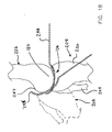
- Figure 18 is an additional side view illustrating an exemplary smoothing step of an exemplary method in accordance with the present invention.
- a lower leg 208 including a tibia 220 and a fibula 222 is shown in figure 18 .
- femoral prep tool 254 is shown interposed between a tibial plateau 134 of tibia 220 and a medial condyle 130 of femur 226.
- force applied to lower leg 208 can be used to press femoral prep tool 254 against medial condyle 130 of femur 226.
- lower leg 208 is disposed in a first position.
- a second position of lower leg 208 is illustrated using dashed lines in figure 18 .
- lower leg 208 is put through a range of motion so that femoral prep tool 254 smooths medial condyle 130.
- This exemplary method may, for example, remove non-bone material from the bone of a femoral condyle to provide a smooth surface.
- Medial condyle 130 can be periodically evaluated for smoothness, for example, by finger palpitation. If there are ridges that can be abrasive to an implant, additional material removal can be required.
- any osteophytes that may impinge on an implant or limit range of motion are removed prior to insertion of the implant.
- a distal tip 255 of femoral prep tool 254 is configured for removing osteophytes from a posterior surface 257 of the femur.
- FIG 19 is a front view of a measuring device 162 in accordance with the present invention.
- Measuring device 162 of figure 19 includes a handle assembly 278 and gauge portion 280.
- the distal end of gauge portion 280 is preferably adapted to engage (e.g., hook over) the posterior edge of the tibial plateau.
- the gauge is sized so that it can be positioned without interference from the femoral condyle.
- a slide 282 having raised contact end portion 284, which translates back and forth relative to rule 286 can be positioned against the anterior portion of the tibia.
- a locking screw 288 is provided for selectively precluding relative motion between slide 282 and rule 286..
- Measuring device 162 of figure 19 also includes a probe 290 that can be positioned along the length of rule 286, and optionally moved laterally thereto, in order to measure the depth of any indentation, or bowl shape that the tibial surface may have.
- probe 290 is mounted on a slide, moveable longitudinally with the axis of rule 286, to permit it to be adjusted to make depth measurements in various locations. These dimensions provide for characterization of the tibial surface and allow for proper sizing of an implant.
- Figure 20 is a rear view of measuring device 162 shown in the previous figure.
- probe 290 comprises a tip portion 292 and an arm portion 294.
- probe 290 pivots about a pivot axis 296.
- Figure 21 is a side view illustrating a measuring method.
- measuring device 162 is interposed between a condyle 298 of a femur 226 and a tibial plateau of a tibia 220.
- measuring device 162 is sized so that it can extend through the space between a femoral condyle and a tibia without substantially interfering with the femoral condyle and the tibia.
- An anterior-posterior dimension can be read from rule 286 as the distance between the point contacting the posterior tibial surface edge and a point contacting the anterior edge.
- An exemplary method of measuring an extent of a tibial plateau and the depth of a tibial dish can comprise the following steps:
- the device and method illustrated in figure 21 is particularly adapted for use in determining an optimal size for an implant to be inserted into the joint.
- the implant is designed to provide a glide path with respect to the femoral condyle.
- Such a device can be used in patients having joints that have progressed to the stage of "bone on bone", and thus provides a replacement for the function of articular cartilage as well as meniscus, and particularly at the central weight-bearing area, in order to restore alignment, providing an elastomeric, cushioning function.
- the present implant is more permanently anchored in place, in significant part by one or more posterior projections, such as the posterior lip, as well by the optional but preferred use of anterior fixation means (such as embedded sutures).
- the depth gauge slide can be moved to a desired point along the axis of the device in order to position the depth probe in a desired location, generally to determine a maximum depth of the tibial surface.
- the probe can be positioned in any suitable fashion, e.g., as a set distance from either the posterior or anterior caliper, or at a midpoint between the two. For the most part, the midpoint of the tibial plateau is going to be very close to the maximum depth of the concavity.
- the probe or other suitable means can also be used to scan or probe the tibial surface in order to identify the particular point of maximum depth.
- FIG 22 is a perspective view of a gripper 164 in accordance with an exemplary embodiment of the present invention.
- Gripper 164 of figure 22 comprises a first jaw 300 and a second jaw 302.
- Gripper 164 can facilitate the insertion of an implant into a joint by providing a means for firmly holding the implant.
- gripper 164 comprises a handle 782 and a hand grip 304.
- Gripper 164 also includes a lock mechanism 306 that can that can be used to lock an implant between first jaw 300 and second jaw 302.
- lock mechanism 306 comprises a knob 308.
- the orientation and configuration of the jaws, and in turn, the manner in which they cooperate to grip an implant are preferably designed to provide an optimal combination of gripping power sufficient for to position the implant, while providing little or no damage to the implant itself.
- Applicants have discovered the manner in which the configuration of a preferred implant itself provides aspects, in terms of raised and thicker portions, that facilitate the use of gripper jaws having a corresponding shape and dimension.
- Figure 23 is a cross-sectional view of gripper 164 shown in the previous figure.
- An implant 320 is held between first jaw 300 and second jaw 302 of gripper 164.
- Lock mechanism 306 comprises a bolt 324 that is pivotally coupled to hand grip 304 by a second dowel 326.
- Other optional lock mechanisms including ratchet and friction type catches.
- bolt 324 is captured relative to handle 782 by a third dowel 328 which extends through an aperture 330 defined by bolt 324.
- a knob 308 and a spring 332 are disposed about bolt 324. Spring 332 can act to bias hand grip 304 toward an extended position relative to handle 782.
- Figure 24 is an exploded view of gripper 164 shown in the previous figure.
- lock mechanism 306 comprises a spring 332, a bolt 324 and a knob 308.
- An aperture 330 defined by bolt 324 is visible in figure 24 .
- aperture 330 is dimensioned so as to allow a third pin 328 to extend through bolt 324.
- a second dowel 326 can be used to pivotally couple bolt 324 to hand grip 304.
- Hand grip 304 can be pivotally coupled to handle 782 by a first dowel 322.
- Figure 25 is a side view showing a leg and a gripper 764.
- An implant 720 is held between a first jaw 700 and a second jaw 702 of gripper 764.
- a gripper us used to hold an anterior portion of an implant while a posterior portion of the implant is inserted between a medial condyle of a femur and tibial plateau of a tibia.
- Figure 26 shows various views of an implant 320 in accordance with an additional exemplary embodiment of the present invention.
- the views of figure 26 include a top view, a section view (B-B) taken along section line B-B of the top view and a section view (C-C) taken along section line C-C of view (a).
- Implant 320 comprises a first major surface 338 adapted to be positioned upon the tibial plateau of a tibia, and a second major surface 340 adapted to be positioned against the medial condyle of a femur.
- Second major surface 340 preferably provides a femoral glide path 342 to facilitate its performance in situ , in the form of a generally central depression 344.
- implant 320 also comprises a mesial ridge 135 extending beyond second major surface 340.
- mesial ridge 135 is dimensioned so as to extend between the medial condyle and the lateral condyle of a femur.
- Figure 27 shows various views of implant 320 shown in the previous figure.
- the views of figure 27 include a bottom view, a section view (B-B) taken along section line B-B of the bottom view and a section view (C-C) taken along section line C-C of view (a).
- Implant 320 comprises a first major surface 338 adapted to be positioned upon the tibial plateau of a tibia, and a second major surface 340 adapted to be positioned against the medial condyle of a femur.
- implant 320 comprises a tibial projection 346 extending beyond first major surface 338.
- tibial projection 346 is adapted to catch a posterior portion of the tibial plateau by extending over the rim of the tibial plateau. Fixation of implant 320 in situ can be accomplished by effectively capping the tibial plateau with tibial projection 346 extending distally over the rim of the plateau at one end of implant 320 and attaching another end of implant 320 with sutures.
- Implant 320 of figure 27 defines a hole 354.
- hole 354 is dimensioned so as to allow one or more sutures to pass through implant 320.
- the first major surface 338 of implant 320 provides with a convex bottom configuration in order to better conform to the cavity of an arthritic posterior tibial plateau.
- FIG 28 is a top view showing an implant 320 including a plurality of tethers 336.
- Tethers 336 can comprise, for example, sutures or fibrous materials that are incorporated into or onto the material of implant 320, for use in improving the initial and/or long term retention of implant 320 in situ , e.g., by tethering implant 320 in a desired position proximate a joint.
- Such other materials can be temporarily positioned into or upon a mold during molding of an implant so that they become integrated into the material of the implant as that material fills the mold.
- tethers 336 can be used to tether the implant, by securing them to the surrounding soft tissue and/or bone by use of adhesives, sutures, screws, pins, staples, or the like, and other types of anchors, or combinations thereof, which in turn can be prepared using bioabsorbable and/or non-bioabsorbable cements, composites, and adhesives.
- the tethers can provide both an immediate fixation function, and optionally also a desired long term function, by permitting them to be either absorbed by the body over time, and/or to permit or encourage fibrous tissue ingrowth for long term fixation.
- Figure 29 is a diagrammatic representation of a stocking set 740 including a plurality of implants 742.
- stocking set 740 includes 36 implants 742 of varying sizes and thicknesses.
- implants 742 are provided in six sizes with each implant size being provided in three different thicknesses. Accordingly, a method for selecting an implant for a particular joint will typically include the step of determining the appropriate implant size and the step of determining an appropriate implant thickness.
- each size has been assigned an identifying character 744.
- identifying character 744 can be one or more arbitrarily selected numbers, letters or combinations of letters and numbers.
- each thickness has been assigned an identifying characteristic 748.
- each identifying characteristic 748 comprises a color. In other words, each implant having a first thickness will be red in color in this exemplary embodiment. Implants having a second thickness and a third thickness will be yellow and blue respectively, in this exemplary embodiment.
- Figure 30 shows a top and side perspective of a preferred preformed knee implant (10) prepared using an ex vivo mold according to the present invention.
- the implant provides a first major surface (12) adapted to be positioned upon the tibial surface, and a generally planar second major surface (14) adapted to be positioned against the femoral condyle.
- the second major surface is preferably provided with a femoral glide path (16) to facilitate its performance in situ , in the form of a generally central (e.g., oval) depression about 0.5 mm, or more preferably about 1 mm to about 5mm deep at its lowest point (2 mm as shown) and about 20 mm, and more preferably about 30 mm to about 50 mm in length by 10 mm to 30 mm in width (40 mm by 20 mm as shown).
- a femoral glide path (16) to facilitate its performance in situ , in the form of a generally central (e.g., oval) depression about 0.5 mm, or more preferably about 1 mm to about 5mm deep at its lowest point (2 mm as shown) and about 20 mm, and more preferably about 30 mm to about 50 mm in length by 10 mm to 30 mm in width (40 mm by 20 mm as shown).
- the implant is also provided with a tibial projection (18), adapted to catch the posterior portion of the tibial plateau by extending over the rim of the tibial plateau distally.
- the body of the implant can have dimensions on the order of between about 35 mm, and preferably about 40 mm to about 60 mm in the anterior-posterior dimension, between about 20 mm, and preferably 30 mm to about 35 mm, or even about 40 mm in the medial-lateral dimension, and a maximum thickness (at the posterior lip of between about 8 mm, more preferably about 10 mm, and about 20 mm, or about 2 mm to about 4 mm (e.g., 3 mm) greater than the thickness of the implant at the center.
- fixation is accomplished by effectively capping the tibial plateau with one or more projections extending distally over the rim of the plateau.
- Figure 31 shows side-by-side top plan views and of corresponding implants for the left and right knees.
- the preformed knee implants of figure 31 include a first major surface adapted to be positioned upon the tibial surface, and a generally planar second major surface adapted to be positioned against the femoral condyle.
- the second major surface is shown having a femoral glide path surface to facilitate its performance in situ, adapted to form a generally central depression having the dimensions described herein.
- the glide path is fully formed in situ, by a suitable combination of both shaping and repositioning of the femoral condyle in the manner described herein.
- An implant of the type shown provides various benefits, including the correction of varus deformities, based in significant part upon the presence and configuration of the posterior mesial lip, and the cutout (kidney bean shaped) for the intercondylar eminence.
- the tibial projection is adapted to catch the posterior portion of the tibial plateau.
- the implant itself has dimensions as provided herein, and can be provided using one of a collection of molds of multiple sizes and/or styles in accordance with the various parameters of the present invention.
- a kit can be provided containing implants of various sizes, e.g., varying by 1 mm increments in thickness and providing a range of anterior to posterior dimensions.
- Such implants can also be provided having bottoms of various shapes, e.g., either a flat or curved bottom, and for either the left or right knee.
- FIG. 32 A further preferred embodiment is shown with respect to Figure 32 , in which the posterior lip is shown as proceeding in a mesial direction so as to occupy the posterior cruciate ligament sulcus when positioned in vivo.
- Figure 32 includes a top view, a sectional view taken section line B-B and a section view taken along section line C-C. Together with the mesial lip, the top of the implant provides a desired glide path, while the bottom of the implant is provided with a convex bottom configuration in order to better conform to the cavity of an arthritic posterior tibial plateau.
- the mesial rim is raised approximately 2mm, reaching highest point as it approaches the intercondylar eminence, in order to add to stability and maintain the overall thickness of the implant.
- the anterior portion of the implant is also provided with additional bulk providing it with a slightly wedge-shaped anterior region sloping from the base of the posterior lip to the anterior edge, in order to improve its posterior directional stability.
- a slight amount of material is removed from the anterior mesial portion to form a cavity that is dimensioned so as to reduce the likelihood that the implant will impinge on the fermoral condyle and perhaps even the medial border of the patella.
- the lip is lengthened a bit, so that with a 54 mm implant (measured as the longest dimension from the most anterior point to the upper inner radius or the posterior lip), the lip is shown as being on the order of 6 mm in height.
- additional bulk is removed from the top, permitting the glide path to remain open in a posterior direction. This configuration allows for more complete flexion, lessening the extent to which the implant might impinge on the cartilage of the posterior medial femoral condyle, together with improved retention within the joint.
- the tibial plateau is congruent to the bottom of the implant.
- the tibial plateau is itself prepared to provide good fit on the tibial side of the implant, while the femoral surface of the implant can be smoothed and opened up so as to be amenable with most any femoral geometry.
- Figure 33 includes three additional plan views the implant shown in the previous figure.
- Figure 33 includes a top plan view that is similar to the top view of the previous figure.
- Figure 33 also includes a side view showing the posterior lip of the implant, and a front view.
- Figure 34 shows various views of an implant in accordance with an exemplary embodiment of the present invention.
- a distance A is shown extending from the most anterior point of the implant to the upper inner radius of the posterior lip of the implant.
- a distance B is also illustrated in figure 34 .
- Distance B can be described as the height of the posterior lip.
- Distances C, D, and E are also illustrated in figure 34 .
- the dimensions of the implant can be scaled to fit a particular size of patient.
- distance A is about 54.0 mm
- distance B is about 5.6 mm
- distance C is about 7.0 mm
- distance D is about 29.2 mm
- distance E is about 2.1 mm.
- distance A is, for example, between about 30 mm and about 60 mm.
- distance B is, for example, between about 1 mm and about 10 mm.
- distance C is, for example, between about 1 mm and about 10 mm.
- distance D is, for example, between about 10 mm and about 40 mm.
- distance E is, for example, between about 0.2 mm and about 4 mm.
- Implants such as those described above are preferably used in a method that includes first determining the proper implant thickness needed to match physiological valgus.
- the surgeon prepares the site arthroscopically, removing excess cartilage and removing the medial meniscus to the medial ring, using a portal of about 1 cm in order to provide suitable arthroscopic access while maintaining the presence of fluid in the joint.
- the implant can be initially molded ex vivo, using a mold selected from those available and including one or more embedded or attached fixation portions (e.g., anterior sutures or tabs), at which time it is inserted into the knee.
- surgeon will then typically feel the implant once in position, to confirm that the implant is properly seated, and will extend the knee to provide varus stress on the lower leg, obtaining congruency as the implant continues to cure by finally molding both surfaces of the implant (to both the tibial surface and condyle, respectively).
- Figure 35 includes a number of views showing an implant template 878 in accordance with the present invention. More particularly, figure 35 includes a top view 884, a side view 888, and an end view 887. With reference to figure 35 , it will be appreciated the implant template 878 comprises an implant-like portion 890 and a handle 882. Implant-like portion 890 comprises a first member 338 adapted to be positioned upon the tibial plateau of a tibia, and a second member 340 adapted to be positioned against the medial condyle of a femur. As shown in figure 35 , implant-like portion 890 also comprises a plurality of shims 895.
- a thickness of implant-like portion 890 of implant template 878 can be varied by changing the quantity and/or thickness of the shims 895 disposed between first member 338 and second member 340.
- shims 895 can be slid between first member 338 and second member 340 from the handle end of implant template 878.
- shims 895 can be slid between first member 338 and second member 340 from the handle end of implant template 878 while implant-like portion 890 is disposed between a femur and a tibia.
Claims (25)
- Système d'implant d'interposition destiné à la création ou à la modification d'une articulation orthopédique d'un corps de mammifère, le système (154) comprenant un ou plusieurs appareils destinés à chacune des étapes consistant à : a) préparer l'articulation à recevoir l'implant d'interposition (156, 158, 160, 254), l'appareil comprenant un dispositif de lissage destiné à préparer une ou plusieurs surfaces situées à l'intérieur du site de l'articulation ; b) déterminer une dimension d'implant appropriée à une articulation particulière (162), l'appareil comprenant un pied à coulisse apte à mesurer une ou plusieurs dimensions de l'articulation ; c) déterminer une épaisseur d'implant appropriée (170, 172), l'appareil destiné à déterminer une épaisseur d'implant appropriée comprenant une pluralité d'implants d'essai dont une ou plusieurs dimensions et/ou configurations varient ; et d) insérer l'implant dans l'articulation (164), l'appareil comprenant une pluralité de mâchoires se faisant face.
- Système selon la revendication 1 comprenant en outre un ou plusieurs dispositifs destinés à fixer l'implant dans l'articulation dans la mesure souhaitée en utilisant une pluralité d'attaches.
- Système selon la revendication 1 ou 2, dans lequel le dispositif de lissage destiné à la préparation d'une ou de plusieurs surfaces à l'intérieur d'un site d'articulation, comprend une lame substantiellement plate, rectiligne ou courbe comportant une partie proximale apte à être tenue à la main et/ou à être fixée à un instrument chirurgical alimenté en énergie et une partie distale ayant au moins une surface importante dotée d'une texture apte à lisser le cartilage situé dans le site de l'articulation.
- Système selon la revendication 3, dans lequel la lame est fabriquée en acier inoxydable chirurgical, et une partie distale de la lame est texturée en ménageant soit une pluralité de trous espacés de façon serrée s'étendant sur la largeur de la lame, soit une pluralité d'aspérités ou de nervures positionnées sur la lame.
- Système selon l'une quelconque des revendications qui précèdent, dans lequel le pied à coulisse comprend un dispositif apte à être utilisé dans le genou afin de déterminer une distance entre les bords antérieur et postérieur de la surface du tibia tout en procurant également une mesure de profondeur adéquate du creux du tibia en un point situé approximativement à mi-chemin entre les bords antérieur et postérieur relevés du plateau tibial.
- Système selon la revendication 5, dans lequel le pied à coulisse est apte à mesurer une ou plusieurs dimensions en rapport avec le genou, comprenant la mesure d'une ou de plusieurs dimensions choisies dans le groupe consistant en une dimension antérieure-postérieure, une dimension médiane-latérale, et une dimension hauteur-profondeur.
- Système selon l'une quelconque des revendications qui précèdent, dans lequel la pluralité d'implants d'essai comprend une pluralité d'implants destinés au genou, d'épaisseurs variées, pour tenir compte du relâchement du ligament dans une articulation du genou spécifique et elle incorpore une caractéristique de conception choisie dans le groupe constitué des codes numériques, des codes barres, des codes de forme, des codes tactiles et/ou des codes visuels.
- Système selon l'une quelconque des revendications qui précèdent, dans lequel la pluralité de mâchoires opposées destinées à l'insertion de l'implant comprend en outre une poignée et un mécanisme de verrouillage apte à fixer les mâchoires en place sur un implant.
- Système selon l'une quelconque des revendications qui précèdent, comprenant en outre un ou plusieurs composants subordonnés aptes à fixer un implant dans le corps.
- Système selon la revendication 2, dans lequel :a. le dispositif de lissage est destiné à préparer une ou plusieurs surfaces à l'intérieur du site de l'articulation, ce dispositif de lissage comprenant une lame substantiellement plate, rectiligne ou courbe, comportant une partie proximale apte à être tenue à la main et/ou fixée à un instrument chirurgical alimenté en énergie, et une partie distale ayant au moins une surface importante dotée d'une texture apte à lisser le cartilage situé dans le site de l'articulation ;b. le pied à coulisse est apte à être utilisé dans le genou afin de déterminer une distance entre les bords antérieur et postérieur de la surface du tibia, tout en procurant également une mesure adéquate de la profondeur du creux du tibia en un point situé approximativement à mi-chemin entre les bords antérieur et postérieur relevés du plateau tibial ;c. l'appareil destiné à déterminer l'épaisseur de l'articulation comprend une pluralité d'implants d'essai d'une ou de plusieurs dimensions et/ou configurations qui varient ;d. la pluralité de mâchoires qui se font face comprend en outre une poignée et un mécanisme de verrouillage apte à fixer les mâchoires en place sur un implant ;e. la pluralité d'attaches comprend un ou plusieurs composants subordonnés intégrés dans et s'étendant partiellement à partir de l'implant pour en assurer la fixation ; etf. un ou plusieurs implants d'interposition dans lesquels au moins un implant comprend un composant en métal ou en polymère partiellement ou complètement préformé, apte à être inséré et positionné sur un site d'articulation pour procurer un implant ayant au moins une surface importante appliquée sur l'os de support et au moins une deuxième surface importante appliquée sur l'os opposé.
- Système selon la revendication 3, dans lequel la lame est apte à être utilisée avec une ou plusieurs surfaces des os de l'articulation du genou et le dispositif est apte à être utilisé pour lisser la surface condylaire.
- Système selon la revendication 3, dans lequel la lame est fabriquée en acier inoxydable chirurgical, une partie distale de la lame est texturée en ménageant soit une pluralité de trous espacés de façon serrée s'étendant sur la largeur de la lame, ou une pluralité d'aspérités ou de rides positionnées sur la lame, le dispositif est apte à être utilisé dans un instrument du type scie à va-et-vient et il est fabriqué de manière à maintenir une forme courbe prédéterminée, le dispositif à une longueur hors-tout comprise entre environ 100 mm et environ 150 mm, avec une partie substantiellement distale ayant une longueur comprise entre environ 20 mm et environ 40 mm, la largeur de la lame est comprise entre environ 5 mm et environ 10 mm, et elle a une épaisseur comprise entre environ 0,3 mm et environ 5 mm, et la partie proximale du dispositif est ménagée sous forme d'une tige généralement circulaire, apte à être positionnée de façon fixe et détachable dans un instrument chirurgical alimenté en énergie.
- Système selon la revendication 12, dans lequel l'instrument chirurgical alimenté en énergie est apte à faire fonctionner la lame à une distance d'excursion comprise entre environ 0,5 mm et environ 10 mm.
- Système selon la revendication 1 ou 2, dans lequel le pied à coulisse est apte à mesurer une ou plusieurs dimensions en rapport avec le genou.
- Système selon la revendication 14, dans lequel le pied à coulisse est apte à mesurer une ou plusieurs dimensions choisies parmi le groupe constitué d'une dimension antérieure-postérieure, d'une dimension médiane-latérale, et d'une dimension hauteur-profondeur et le dispositif est apte à être utilisé dans le genou et il peut être utilisé pour mesurer une distance entre les bords antérieur et postérieur de la surface du tibia, tout en procurant une mesure adéquate de la profondeur du creux du tibia en un point situé approximativement à mi-chemin entre les bords antérieur et postérieur relevés du plateau tibial.
- Système selon la revendication 14, dans lequel le pied à coulisse comprend un ensemble de poignée et une partie jauge apte à se mettre en contact avec le bord postérieur du plateau tibial et sans interférence provenant du condyle fémoral, comprenant en outre un coulisseau comportant une partie d'extrémité de contact relevée qui se déplace en translation en va-et-vient par rapport à une règle qui peut être positionnée contre la partie antérieure du tibia, comprenant en outre une sonde positionnée sur la longueur de la règle et pouvant être optionnellement déplacée latéralement, afin de mesurer la profondeur de n'importe quelle indentation, ou forme de coupe, que peut comporter la surface du tibia, la sonde étant montée sur un coulisseau, apte à être déplacé longitudinalement à l'axe de la règle, pour permettre un réglage en vue d'effectuer des mesures de profondeur à divers emplacements et la dimension antérieure-postérieure de la surface du tibia peut être lue sur la règle sous forme de la distance séparant le point de contact avec le bord postérieur de la surface du tibia et un point de contact avec le bord antérieur.
- Système selon la revendication 14 comprenant un pied à coulisse apte à mesurer une ou plusieurs dimensions en rapport avec le genou, comprenant la mesure d'une ou de plusieurs dimensions choisies dans le groupe constitué par une dimension antérieure-postérieure, par une dimension médiane-latérale et par une dimension hauteur-profondeur.
- Système selon la revendication 1 ou 2, dans lequel la pluralité de mâchoires qui se font face est apte à tenir fermement un implant d'interposition pour le genou et elle comprend en outre une poignée et un mécanisme de verrouillage apte à fixer les mâchoires en place sur un implant, les première et deuxième mâchoires sont accouplées de façon pivotante à la poignée et elles comprennent en outre une partie apte à pousser la poignée en position d'ouverture.
- Système selon la revendication 1 ou 2, dans lequel la pluralité de mâchoires qui se font face est apte à maintenir une partie antérieure d'un implant pendant qu'une partie postérieure de l'implant est insérée entre le condyle médian d'un fémur et le plateau tibial d'un tibia.
- Système selon la revendication 2 comprenant une pluralité d'attaches dotées d'un ou de plusieurs composants subordonnés aptes à fixer un implant.
- Système selon la revendication 20, dans lequel au moins un composant subordonné est intégré dans et s'étend partiellement depuis l'implant afin de procurer une fixation antérieure.
- Système selon la revendication 21, dans lequel le composant subordonné comprend une ou plusieurs saillies aptes à être fixées à un tissu lisse et/ou à un os lisse au niveau du site de l'articulation pour améliorer la fixation et les saillies sont choisies dans le groupe constitué de sutures et/ou de biomatériaux fibreux formés d'un seul tenant avec le composant préformé lui-même, et un ou plusieurs composants séparés destinés à fixer l'implant au site d'articulation, lesquels sont choisis dans le groupe constitué d'adhésifs, de sutures d'épingles, d'agrafes, de vis et de combinaisons de ceux-ci.
- Système selon les revendications 1 ou 2, comprenant en outre un ou plusieurs implants d'interposition.
- Système selon la revendication 23, dans lequel au moins un implant comprend un composant en métal et/ou en polymère partiellement ou complètement préformé, apte à être inséré et positionné au niveau d'un site d'articulation pour procurer un implant ayant au moins une surface importante appliquée à l'os de support, et au moins une deuxième surface importante appliquée à l'os opposé, l'implant comprend un implant pour le genou, l'implant procure un chemin de glissement fémoral et une convexité de la surface tibiale de l'implant en même temps qu'une lèvre médiane postérieure, les composants polymères sont fournis sous la forme d'un composant préformé unique comprenant un biomatériau partiellement ou complètement durci dans un moule ex vivo, l'implant comprend une(des) saillie(s) tibiale(s) apte(s) à s'accrocher sur la partie postérieure du plateau tibial en s'étendant distalement au-dessus du bord du plateau tibial, et le composant préformé a des dimensions de l'ordre compris entre environ 30 mm et environ 60 mm dans la dimension antérieure-postérieure, entre environ 20 mm et environ 40 mm dans la dimension médiane-latérale et une épaisseur maximum au niveau de la lèvre postérieure comprise entre environ 8 mm et environ 20 mm, ou supérieure d'environ 3 mm à environ 10 mm à l'épaisseur de l'implant au centre.
- Système selon la revendication 24, dans lequel l'implant comprend en outre au moins un composant subordonné intégré dans et s'étendant partiellement depuis l'implant afin de procurer une fixation antérieure.
Applications Claiming Priority (7)
| Application Number | Priority Date | Filing Date | Title |
|---|---|---|---|
| US40883 | 2002-01-07 | ||
| US39530102P | 2002-07-11 | 2002-07-11 | |
| US395301P | 2002-07-11 | ||
| PCT/US2002/040883 WO2003053278A2 (fr) | 2001-12-19 | 2002-12-19 | Procede et systeme de lissage osseux |
| PCT/US2003/002142 WO2003061522A2 (fr) | 2002-01-22 | 2003-01-22 | Systeme et procede d'arthroplastie avec interposition |
| US2142 | 2003-01-22 | ||
| PCT/US2003/021513 WO2004006811A2 (fr) | 2002-07-11 | 2003-07-10 | Procede et trousse pour arthroplastie avec interposition |
Publications (2)
| Publication Number | Publication Date |
|---|---|
| EP1523291A2 EP1523291A2 (fr) | 2005-04-20 |
| EP1523291B1 true EP1523291B1 (fr) | 2008-06-18 |
Family
ID=36928878
Family Applications (1)
| Application Number | Title | Priority Date | Filing Date |
|---|---|---|---|
| EP03764417A Expired - Lifetime EP1523291B1 (fr) | 2002-07-11 | 2003-07-10 | Trousse pour arthroplastie avec interposition |
Country Status (8)
| Country | Link |
|---|---|
| US (1) | US20060111726A1 (fr) |
| EP (1) | EP1523291B1 (fr) |
| AT (1) | ATE398432T1 (fr) |
| AU (1) | AU2003247952A1 (fr) |
| CA (1) | CA2492030A1 (fr) |
| DE (1) | DE60321683D1 (fr) |
| ES (1) | ES2309350T3 (fr) |
| WO (1) | WO2004006811A2 (fr) |
Cited By (1)
| Publication number | Priority date | Publication date | Assignee | Title |
|---|---|---|---|---|
| WO2024064891A1 (fr) * | 2022-09-22 | 2024-03-28 | Abyrx, Inc. | Moules pour compositions multi-composants durcissables et procédé de formation desdites compositions |
Families Citing this family (105)
| Publication number | Priority date | Publication date | Assignee | Title |
|---|---|---|---|---|
| US10085839B2 (en) | 2004-01-05 | 2018-10-02 | Conformis, Inc. | Patient-specific and patient-engineered orthopedic implants |
| US8882847B2 (en) | 2001-05-25 | 2014-11-11 | Conformis, Inc. | Patient selectable knee joint arthroplasty devices |
| US9603711B2 (en) | 2001-05-25 | 2017-03-28 | Conformis, Inc. | Patient-adapted and improved articular implants, designs and related guide tools |
| US8545569B2 (en) | 2001-05-25 | 2013-10-01 | Conformis, Inc. | Patient selectable knee arthroplasty devices |
| US8771365B2 (en) | 2009-02-25 | 2014-07-08 | Conformis, Inc. | Patient-adapted and improved orthopedic implants, designs, and related tools |
| US8556983B2 (en) | 2001-05-25 | 2013-10-15 | Conformis, Inc. | Patient-adapted and improved orthopedic implants, designs and related tools |
| US8735773B2 (en) | 2007-02-14 | 2014-05-27 | Conformis, Inc. | Implant device and method for manufacture |
| US8480754B2 (en) | 2001-05-25 | 2013-07-09 | Conformis, Inc. | Patient-adapted and improved articular implants, designs and related guide tools |
| US7239908B1 (en) | 1998-09-14 | 2007-07-03 | The Board Of Trustees Of The Leland Stanford Junior University | Assessing the condition of a joint and devising treatment |
| ATE439806T1 (de) | 1998-09-14 | 2009-09-15 | Univ Leland Stanford Junior | Zustandsbestimmung eines gelenks und schadenvorsorge |
| US9289153B2 (en) * | 1998-09-14 | 2016-03-22 | The Board Of Trustees Of The Leland Stanford Junior University | Joint and cartilage diagnosis, assessment and modeling |
| US20050209703A1 (en) * | 1999-04-02 | 2005-09-22 | Fell Barry M | Surgically implantable prosthetic system |
| ATE426357T1 (de) | 2000-09-14 | 2009-04-15 | Univ Leland Stanford Junior | Beurteilung des zustandes eines gelenkes und planung einer behandlung |
| AU2001290887B2 (en) | 2000-09-14 | 2006-06-08 | The Board Of Trustees Of The Leland Stanford Junior University | Assessing condition of a joint and cartilage loss |
| CA2447694A1 (fr) | 2001-05-25 | 2002-12-05 | Imaging Therapeutics, Inc. | Methodes et compositions d'arthroplastie |
| US20070156171A1 (en) * | 2001-05-25 | 2007-07-05 | Conformis, Inc. | Implant Grasper |
| TWI231755B (en) * | 2002-10-07 | 2005-05-01 | Conformis Inc | An interpositional articular implant and the method for making the same |
| JP2006505366A (ja) | 2002-11-07 | 2006-02-16 | コンフォーミス・インコーポレイテッド | 半月板サイズおよび形状の決定および工夫した処置の方法 |
| EP1686932B1 (fr) | 2003-06-27 | 2010-01-06 | ABS Corporation | Systeme destines a l'arthroplastie de la cheville |
| US20090088846A1 (en) | 2007-04-17 | 2009-04-02 | David Myung | Hydrogel arthroplasty device |
| US7857851B2 (en) | 2004-10-29 | 2010-12-28 | Depuy Products, Inc. | Implant system with sizing templates |
| US8668699B2 (en) * | 2005-04-14 | 2014-03-11 | Warsaw Orthopedic, Inc. | Multi-function orthopedic instrument |
| EP2649951A3 (fr) | 2006-02-06 | 2013-12-25 | ConforMIS, Inc. | Dispositifs d'arthroplastie articulaire et outils chirurgicaux selectionnables par le patient |
| AU2007243353B2 (en) * | 2006-04-26 | 2012-05-31 | Illuminoss Medical, Inc. | Apparatus and methods for reinforcing bone |
| US7806900B2 (en) | 2006-04-26 | 2010-10-05 | Illuminoss Medical, Inc. | Apparatus and methods for delivery of reinforcing materials to bone |
| WO2008045807A2 (fr) | 2006-10-09 | 2008-04-17 | Active Implants Corporation | Dispositif de prothèse de ménisque |
| US8192491B2 (en) | 2006-10-09 | 2012-06-05 | Active Implants Corporation | Meniscus prosthetic device |
| US7879041B2 (en) * | 2006-11-10 | 2011-02-01 | Illuminoss Medical, Inc. | Systems and methods for internal bone fixation |
| WO2008063265A1 (fr) | 2006-11-10 | 2008-05-29 | Illuminoss Medical, Inc. | Systèmes et procédés pour une fixation d'os interne |
| WO2008101090A2 (fr) | 2007-02-14 | 2008-08-21 | Conformis, Inc. | Dispositif d'implant et procédé de fabrication |
| US9427289B2 (en) | 2007-10-31 | 2016-08-30 | Illuminoss Medical, Inc. | Light source |
| US8403968B2 (en) | 2007-12-26 | 2013-03-26 | Illuminoss Medical, Inc. | Apparatus and methods for repairing craniomaxillofacial bones using customized bone plates |
| US8682052B2 (en) | 2008-03-05 | 2014-03-25 | Conformis, Inc. | Implants for altering wear patterns of articular surfaces |
| CA2718718A1 (fr) * | 2008-03-21 | 2009-09-24 | Biomimedica, Inc | Procedes, dispositifs et compositions permettant de faire adherer des implants polymeres hydrates sur un os |
| US8016884B2 (en) | 2008-04-09 | 2011-09-13 | Active Implants Corporation | Tensioned meniscus prosthetic devices and associated methods |
| US7991599B2 (en) | 2008-04-09 | 2011-08-02 | Active Implants Corporation | Meniscus prosthetic device selection and implantation methods |
| US7611653B1 (en) * | 2008-04-09 | 2009-11-03 | Active Implants Corporation | Manufacturing and material processing for prosthetic devices |
| US8361147B2 (en) * | 2008-04-09 | 2013-01-29 | Active Implants Corporation | Meniscus prosthetic devices with anti-migration features |
| WO2009140294A1 (fr) | 2008-05-12 | 2009-11-19 | Conformis, Inc. | Dispositifs et procédés pour le traitement de facette et d’autres articulations |
| EP2297217B1 (fr) * | 2008-07-07 | 2021-10-20 | Hyalex Orthopaedics, Inc. | Alliage ipn hydrophile issu de polymères hydrophobes |
| US20120209396A1 (en) | 2008-07-07 | 2012-08-16 | David Myung | Orthopedic implants having gradient polymer alloys |
| GB0812555D0 (en) | 2008-07-10 | 2008-08-13 | Depuy Int Ltd | Container and system of containers of surgical instruments |
| AU2009279716A1 (en) | 2008-08-05 | 2010-02-11 | Biomimedica, Inc | Polyurethane-grafted hydrogels |
| DE102008052680A1 (de) * | 2008-10-22 | 2010-04-29 | Surgitaix Ag | Vorrichtung zur kontrollierten Einstellung einer chirurgischen Positioniereinheit |
| US9271848B2 (en) | 2008-10-24 | 2016-03-01 | The Cleveland Clinic Foundation | Prosthetic joint component planning template |
| US9017414B2 (en) * | 2008-11-18 | 2015-04-28 | Howmedica Osteonics Corp. | Trial implant and method of use |
| WO2010099231A2 (fr) | 2009-02-24 | 2010-09-02 | Conformis, Inc. | Systèmes automatisés de fabrication d'implants orthopédiques spécifiques au patient et instrumentation |
| US8210729B2 (en) | 2009-04-06 | 2012-07-03 | Illuminoss Medical, Inc. | Attachment system for light-conducting fibers |
| US8512338B2 (en) | 2009-04-07 | 2013-08-20 | Illuminoss Medical, Inc. | Photodynamic bone stabilization systems and methods for reinforcing bone |
| US9168106B2 (en) * | 2009-05-05 | 2015-10-27 | Blue Ortho | Device and method for instrument adjustment in computer assisted surgery |
| BR112012003783A2 (pt) | 2009-08-19 | 2016-04-19 | Illuminoss Medical Inc | dispositivos e métodos para alinhamento, estabilização e distração óssea |
| US8684965B2 (en) | 2010-06-21 | 2014-04-01 | Illuminoss Medical, Inc. | Photodynamic bone stabilization and drug delivery systems |
| US8764840B2 (en) | 2010-07-24 | 2014-07-01 | Zimmer, Inc. | Tibial prosthesis |
| RU2573939C2 (ru) | 2010-07-24 | 2016-01-27 | Зиммер, Инк. | Большеберцовый протез (варианты) |
| US20130217829A1 (en) | 2010-08-27 | 2013-08-22 | David Myung | "hydrophobic and hydrophilic interpenetrating polymer networks derived from hydrophobic polymers and methods of preparing the same" |
| US10376370B2 (en) | 2010-09-07 | 2019-08-13 | John Joseph O'Connor | Unicondylar meniscal bearing knee replacement |
| GB201014824D0 (en) | 2010-09-07 | 2010-10-20 | Goodfellow John | Unicondylar meniscal bearing knee replacement |
| EP3348236B1 (fr) | 2010-09-10 | 2019-11-20 | Zimmer, Inc. | Composants tibiaux facilitant le mouvement pour une prothèse du genou |
| US9597090B2 (en) | 2010-12-17 | 2017-03-21 | Zimmer, Inc. | Cut guide attachment for use in tibial prosthesis systems |
| US8603101B2 (en) | 2010-12-17 | 2013-12-10 | Zimmer, Inc. | Provisional tibial prosthesis system |
| US9149206B2 (en) | 2012-03-30 | 2015-10-06 | Zimmer, Inc. | Tibial prosthesis systems, kits, and methods |
| WO2012088432A1 (fr) | 2010-12-22 | 2012-06-28 | Illuminoss Medical, Inc. | Systèmes et méthodes de traitement d'affections et de maladies touchant la colonne vertébrale |
| CN103476363B (zh) | 2011-02-15 | 2017-06-30 | 康复米斯公司 | 改进的适合患者型关节植入物以及处理、评估、校正、修改和/或适应解剖变化和/或非对称性的手术和工具 |
| US9861372B2 (en) | 2011-05-27 | 2018-01-09 | Howmedica Osteonics Corp. | Prosthetic implant and associated instruments |
| US9144442B2 (en) | 2011-07-19 | 2015-09-29 | Illuminoss Medical, Inc. | Photodynamic articular joint implants and methods of use |
| US8936644B2 (en) | 2011-07-19 | 2015-01-20 | Illuminoss Medical, Inc. | Systems and methods for joint stabilization |
| US9198676B2 (en) | 2011-07-26 | 2015-12-01 | Howmedica Osteonics Corp. | PCL guides for drilling tibial and femoral tunnels |
| GB201113968D0 (en) | 2011-08-15 | 2011-09-28 | Univ Cardiff | Prognostic methadology |
| GB201114059D0 (en) * | 2011-08-16 | 2011-09-28 | Depuy Ireland | Attachment mechanism |
| US20130103157A1 (en) | 2011-10-03 | 2013-04-25 | Lampros Kourtis | Polymeric adhesive for anchoring compliant materials to another surface |
| US8523875B2 (en) * | 2011-10-11 | 2013-09-03 | Smith & Nephew, Inc. | Graft caliper marking device |
| WO2013074145A1 (fr) | 2011-11-18 | 2013-05-23 | Zimmer, Inc. | Élément porteur tibial pour prothèse du genou présentant des caractéristiques articulaires améliorées |
| AU2012340699A1 (en) | 2011-11-21 | 2014-06-19 | Biomimedica, Inc. | Systems, devices, and methods for anchoring orthopaedic implants to bone |
| EP2782525B1 (fr) | 2011-11-21 | 2016-07-20 | Zimmer, Inc. | Plaque de base tibiale avec placement asymétrique de structures de fixation |
| CA2863375C (fr) | 2012-01-30 | 2019-07-16 | Mary S.S. Wentorf | Elements tibiaux asymetriques pour une prothese de genou |
| US10709482B2 (en) * | 2012-05-30 | 2020-07-14 | Globus Medical, Inc. | Laminoplasty system |
| US9675471B2 (en) | 2012-06-11 | 2017-06-13 | Conformis, Inc. | Devices, techniques and methods for assessing joint spacing, balancing soft tissues and obtaining desired kinematics for joint implant components |
| US8939977B2 (en) | 2012-07-10 | 2015-01-27 | Illuminoss Medical, Inc. | Systems and methods for separating bone fixation devices from introducer |
| US9687281B2 (en) | 2012-12-20 | 2017-06-27 | Illuminoss Medical, Inc. | Distal tip for bone fixation devices |
| US9925052B2 (en) | 2013-08-30 | 2018-03-27 | Zimmer, Inc. | Method for optimizing implant designs |
| US9592133B2 (en) | 2013-09-23 | 2017-03-14 | Zimmer, Inc. | Spacer block |
| CN103815908B (zh) * | 2014-03-03 | 2017-02-15 | 上海市杨浦区中心医院 | 胫骨假体尺寸测量器 |
| US20160310043A1 (en) * | 2015-04-26 | 2016-10-27 | Endochoice, Inc. | Endoscopic Polyp Measurement Tool and Method for Using the Same |
| US11077228B2 (en) | 2015-08-10 | 2021-08-03 | Hyalex Orthopaedics, Inc. | Interpenetrating polymer networks |
| WO2017053196A1 (fr) | 2015-09-21 | 2017-03-30 | Zimmer, Inc. | Système de prothèse comprenant un composant de support tibial |
| US10631882B2 (en) * | 2016-04-28 | 2020-04-28 | David K. Boger | Oscillating decortication burr assembly |
| US10617433B2 (en) * | 2016-04-28 | 2020-04-14 | David K. Boger | Oscillating decortication burr assembly |
| US11090164B2 (en) | 2016-10-12 | 2021-08-17 | Corentec Co. Ltd. | Knee joint implant |
| CA3046648A1 (fr) * | 2016-12-13 | 2018-06-21 | Aurora Spine, Inc. | Implants orthopediques correspondant a un resultat de balayage de densite corporelle et procedes d'utilisation |
| US11266512B2 (en) | 2016-12-22 | 2022-03-08 | Orthosensor Inc. | Surgical apparatus to support installation of a prosthetic component and method therefore |
| US11185425B2 (en) | 2016-12-22 | 2021-11-30 | Orthosensor Inc. | Surgical tensor configured to distribute loading through at least two pivot points |
| US11291437B2 (en) | 2016-12-22 | 2022-04-05 | Orthosensor Inc. | Tilting surgical tensor to support at least one bone cut |
| US11284873B2 (en) | 2016-12-22 | 2022-03-29 | Orthosensor Inc. | Surgical tensor where each distraction mechanism is supported and aligned by at least two guide shafts |
| US11129605B2 (en) | 2016-12-22 | 2021-09-28 | Orthosensor Inc. | Surgical apparatus to support installation of a prosthetic component and method therefore |
| ES2878003T3 (es) | 2017-03-10 | 2021-11-18 | Zimmer Inc | Prótesis tibial con característica de afianzamiento para un componente de apoyo tibial |
| CA3063415C (fr) | 2017-05-12 | 2021-10-19 | Zimmer, Inc. | Protheses femorales presentant des capacites d'agrandissement et de reduction de taille |
| US10940022B2 (en) | 2017-09-19 | 2021-03-09 | Depuy Ireland Unlimited Company | Side-specific orthopaedic surgical instrument systems and associated methods of use |
| US11426282B2 (en) | 2017-11-16 | 2022-08-30 | Zimmer, Inc. | Implants for adding joint inclination to a knee arthroplasty |
| US10835380B2 (en) | 2018-04-30 | 2020-11-17 | Zimmer, Inc. | Posterior stabilized prosthesis system |
| EP3813696A4 (fr) | 2018-06-27 | 2022-04-13 | IlluminOss Medical, Inc. | Systèmes et méthodes de stabilisation et de fixation osseuse |
| US10869950B2 (en) | 2018-07-17 | 2020-12-22 | Hyalex Orthopaedics, Inc. | Ionic polymer compositions |
| US11129732B2 (en) | 2019-04-23 | 2021-09-28 | X40, Inc. | Systems and methods for selecting artificial femoral components |
| US11819423B2 (en) | 2019-04-23 | 2023-11-21 | X40, Inc. | Systems and methods for selecting artificial femoral components |
| US11357645B2 (en) | 2020-04-17 | 2022-06-14 | Warsaw Orthopedic, Inc. | Implant with graded radiopacity calibration feature |
| WO2022192250A1 (fr) * | 2021-03-09 | 2022-09-15 | Biopoly, Llc | Ensembles d'implant d'orteil, kits, procédés chirurgicaux et procédés de fabrication |
Citations (2)
| Publication number | Priority date | Publication date | Assignee | Title |
|---|---|---|---|---|
| WO2000059411A1 (fr) * | 1999-04-02 | 2000-10-12 | Fell Barry M | Prothese de genou implantable chirurgicalement |
| US6224630B1 (en) * | 1998-05-29 | 2001-05-01 | Advanced Bio Surfaces, Inc. | Implantable tissue repair device |
Family Cites Families (65)
| Publication number | Priority date | Publication date | Assignee | Title |
|---|---|---|---|---|
| US3030951A (en) * | 1959-04-10 | 1962-04-24 | Michael P Mandarino | Methods and materials for orthopedic surgery |
| US3728742A (en) * | 1971-06-18 | 1973-04-24 | Howmedica | Knee or elbow prosthesis |
| US3815599A (en) * | 1973-03-02 | 1974-06-11 | W Deyerle | Femoral shaft surgical rasp for use in hip prosthesis surgery |
| US4081866A (en) * | 1977-02-02 | 1978-04-04 | Howmedica, Inc. | Total anatomical knee prosthesis |
| US4203444A (en) * | 1977-11-07 | 1980-05-20 | Dyonics, Inc. | Surgical instrument suitable for closed surgery such as of the knee |
| US4185634A (en) * | 1977-12-27 | 1980-01-29 | Freedman Bruce M | Surgical instrument |
| US4312363A (en) * | 1980-02-26 | 1982-01-26 | Senco Products, Inc. | Surgical tissue thickness measuring instrument |
| US4463141A (en) * | 1981-11-30 | 1984-07-31 | E. I. Du Pont De Nemours And Company | Polyether carbonate diols and polyurethanes prepared therefrom |
| US4456745A (en) * | 1982-05-24 | 1984-06-26 | Ethyl Corporation | Polyurethanes prepared from polycarbonates |
| US4477604A (en) * | 1982-09-20 | 1984-10-16 | Oechsle Iii Sixtus J | Polyurethane compositions and their use as luting agents |
| DE3318730A1 (de) * | 1983-05-21 | 1984-11-22 | Akzo Gmbh, 5600 Wuppertal | Biokompatible polyurethane |
| US4722948A (en) * | 1984-03-16 | 1988-02-02 | Dynatech Corporation | Bone replacement and repair putty material from unsaturated polyester resin and vinyl pyrrolidone |
| US4647643A (en) * | 1985-11-08 | 1987-03-03 | Becton, Dickinson And Company | Soft non-blocking polyurethanes |
| US4651736A (en) * | 1986-02-01 | 1987-03-24 | Bruce Sanders | Methods for temporomandibular joint small incision surgery |
| US4743632A (en) * | 1987-02-25 | 1988-05-10 | Pfizer Hospital Products Group, Inc. | Polyetherurethane urea polymers as space filling tissue adhesives |
| DE3717060A1 (de) * | 1987-05-21 | 1988-12-01 | Bayer Ag | Polyether-polycarbonat-diole, ihre herstellung und verwendung als ausgangsprodukte fuer polyurethankunststoffe |
| US5306311A (en) * | 1987-07-20 | 1994-04-26 | Regen Corporation | Prosthetic articular cartilage |
| US4772287A (en) * | 1987-08-20 | 1988-09-20 | Cedar Surgical, Inc. | Prosthetic disc and method of implanting |
| US4880610A (en) * | 1988-04-20 | 1989-11-14 | Norian Corporation | In situ calcium phosphate minerals--method and composition |
| US4873308A (en) * | 1988-09-30 | 1989-10-10 | Medtronic, Inc. | Biostable, segmented aliphatic polyurethanes and process therefor |
| US4938763B1 (en) * | 1988-10-03 | 1995-07-04 | Atrix Lab Inc | Biodegradable in-situ forming implants and method of producing the same |
| US4872452A (en) * | 1989-01-09 | 1989-10-10 | Minnesota Mining And Manufacturing Company | Bone rasp |
| US4969888A (en) * | 1989-02-09 | 1990-11-13 | Arie Scholten | Surgical protocol for fixation of osteoporotic bone using inflatable device |
| US5007940A (en) * | 1989-06-09 | 1991-04-16 | American Medical Systems, Inc. | Injectable polymeric bodies |
| DE4029969A1 (de) * | 1989-09-21 | 1991-04-04 | Asahi Optical Co Ltd | Verfahren zur herstellung von knochenprothesen |
| US5067964A (en) * | 1989-12-13 | 1991-11-26 | Stryker Corporation | Articular surface repair |
| US5254662A (en) * | 1990-09-12 | 1993-10-19 | Polymedia Industries, Inc. | Biostable polyurethane products |
| US5143942A (en) * | 1991-10-28 | 1992-09-01 | Ethyl Corporation | Polyurethanes |
| US5166115A (en) * | 1991-10-28 | 1992-11-24 | Brown William R | Polyurethanes |
| US5509934A (en) * | 1992-02-28 | 1996-04-23 | Osteonics Corp. | Prosthetic knee tibial component constructed of synthetic polymeric material |
| JPH05298662A (ja) * | 1992-04-14 | 1993-11-12 | Fuji Photo Film Co Ltd | 磁気記録媒体用結合剤および磁気記録媒体 |
| US5326366A (en) * | 1993-02-16 | 1994-07-05 | Wright Medical Technology, Inc. | Biomechanical great toe implant |
| US5888220A (en) * | 1994-05-06 | 1999-03-30 | Advanced Bio Surfaces, Inc. | Articulating joint repair |
| US6140452A (en) * | 1994-05-06 | 2000-10-31 | Advanced Bio Surfaces, Inc. | Biomaterial for in situ tissue repair |
| US5556429A (en) * | 1994-05-06 | 1996-09-17 | Advanced Bio Surfaces, Inc. | Joint resurfacing system |
| US20050043808A1 (en) * | 1994-05-06 | 2005-02-24 | Advanced Bio Surfaces, Inc. | Knee joint prosthesis |
| US6248131B1 (en) * | 1994-05-06 | 2001-06-19 | Advanced Bio Surfaces, Inc. | Articulating joint repair |
| US5609642A (en) * | 1995-02-15 | 1997-03-11 | Smith & Nephew Richards Inc. | Tibial trial prosthesis and bone preparation system |
| US5690636A (en) * | 1995-12-21 | 1997-11-25 | Johnson & Johnson Professional, Inc. | Punch system for tibial prosthesis |
| US5725531A (en) * | 1995-12-27 | 1998-03-10 | Shapiro; Jules S. | Reaming device |
| US5984970A (en) * | 1996-03-13 | 1999-11-16 | Bramlet; Dale G. | Arthroplasty joint assembly |
| DE29615920U1 (de) * | 1996-09-12 | 1998-01-15 | Link Waldemar Gmbh Co | Gelenkendoprothese |
| AU7178698A (en) * | 1996-11-15 | 1998-06-03 | Advanced Bio Surfaces, Inc. | Biomaterial system for in situ tissue repair |
| US5725585A (en) * | 1997-02-27 | 1998-03-10 | Zobel; Robert A. | Anatomically correct great toe implant and surgical procedure for implanting the same |
| US6079868A (en) * | 1997-12-18 | 2000-06-27 | Advanced Bio Surfaces, Inc. | Static mixer |
| US6558421B1 (en) * | 2000-09-19 | 2003-05-06 | Barry M. Fell | Surgically implantable knee prosthesis |
| US7341602B2 (en) * | 1999-05-10 | 2008-03-11 | Fell Barry M | Proportioned surgically implantable knee prosthesis |
| US6206927B1 (en) * | 1999-04-02 | 2001-03-27 | Barry M. Fell | Surgically implantable knee prothesis |
| US6048345A (en) * | 1999-04-08 | 2000-04-11 | Joseph J. Berke | Motorized reciprocating surgical file apparatus and method |
| US6923831B2 (en) * | 1999-05-10 | 2005-08-02 | Barry M. Fell | Surgically implantable knee prosthesis having attachment apertures |
| US6966928B2 (en) * | 1999-05-10 | 2005-11-22 | Fell Barry M | Surgically implantable knee prosthesis having keels |
| US6866684B2 (en) * | 1999-05-10 | 2005-03-15 | Barry M. Fell | Surgically implantable knee prosthesis having different tibial and femoral surface profiles |
| US6911044B2 (en) * | 1999-05-10 | 2005-06-28 | Barry M. Fell | Surgically implantable knee prosthesis having medially shifted tibial surface |
| US7297161B2 (en) * | 1999-05-10 | 2007-11-20 | Fell Barry M | Surgically implantable knee prosthesis |
| US6855165B2 (en) * | 1999-05-10 | 2005-02-15 | Barry M. Fell | Surgically implantable knee prosthesis having enlarged femoral surface |
| US6893463B2 (en) * | 1999-05-10 | 2005-05-17 | Barry M. Fell | Surgically implantable knee prosthesis having two-piece keyed components |
| US7491235B2 (en) * | 1999-05-10 | 2009-02-17 | Fell Barry M | Surgically implantable knee prosthesis |
| US6368324B1 (en) * | 1999-09-24 | 2002-04-09 | Medtronic Xomed, Inc. | Powered surgical handpiece assemblies and handpiece adapter assemblies |
| US6764491B2 (en) * | 1999-10-21 | 2004-07-20 | Sdgi Holdings, Inc. | Devices and techniques for a posterior lateral disc space approach |
| WO2001066022A1 (fr) * | 2000-03-10 | 2001-09-13 | Smith & Nephew, Inc | Appareil pour utilisation dans le cadre de l'arthroplastie des genoux |
| EP1315470B1 (fr) * | 2000-08-28 | 2009-07-15 | Disc Dynamics, Inc. | Systeme d'arthroplastie de surface chez les mammiferes |
| US6699252B2 (en) * | 2001-04-17 | 2004-03-02 | Regeneration Technologies, Inc. | Methods and instruments for improved meniscus transplantation |
| GB2399309A (en) * | 2001-12-19 | 2004-09-15 | Advanced Bio Surfaces Inc | Bone smoothing method and system |
| US20040247641A1 (en) * | 2002-01-22 | 2004-12-09 | Felt Jeffrey C. | Interpositional arthroplasty system & method |
| US20040006393A1 (en) * | 2002-07-03 | 2004-01-08 | Brian Burkinshaw | Implantable prosthetic knee for lateral compartment |
-
2003
- 2003-07-10 DE DE60321683T patent/DE60321683D1/de not_active Expired - Lifetime
- 2003-07-10 AT AT03764417T patent/ATE398432T1/de not_active IP Right Cessation
- 2003-07-10 EP EP03764417A patent/EP1523291B1/fr not_active Expired - Lifetime
- 2003-07-10 WO PCT/US2003/021513 patent/WO2004006811A2/fr not_active Application Discontinuation
- 2003-07-10 ES ES03764417T patent/ES2309350T3/es not_active Expired - Lifetime
- 2003-07-10 US US10/520,979 patent/US20060111726A1/en not_active Abandoned
- 2003-07-10 CA CA002492030A patent/CA2492030A1/fr not_active Abandoned
- 2003-07-10 AU AU2003247952A patent/AU2003247952A1/en not_active Abandoned
Patent Citations (2)
| Publication number | Priority date | Publication date | Assignee | Title |
|---|---|---|---|---|
| US6224630B1 (en) * | 1998-05-29 | 2001-05-01 | Advanced Bio Surfaces, Inc. | Implantable tissue repair device |
| WO2000059411A1 (fr) * | 1999-04-02 | 2000-10-12 | Fell Barry M | Prothese de genou implantable chirurgicalement |
Cited By (1)
| Publication number | Priority date | Publication date | Assignee | Title |
|---|---|---|---|---|
| WO2024064891A1 (fr) * | 2022-09-22 | 2024-03-28 | Abyrx, Inc. | Moules pour compositions multi-composants durcissables et procédé de formation desdites compositions |
Also Published As
| Publication number | Publication date |
|---|---|
| ATE398432T1 (de) | 2008-07-15 |
| EP1523291A2 (fr) | 2005-04-20 |
| AU2003247952A1 (en) | 2004-02-02 |
| WO2004006811A2 (fr) | 2004-01-22 |
| US20060111726A1 (en) | 2006-05-25 |
| CA2492030A1 (fr) | 2004-01-22 |
| DE60321683D1 (de) | 2008-07-31 |
| WO2004006811A3 (fr) | 2004-05-21 |
| ES2309350T3 (es) | 2008-12-16 |
Similar Documents
| Publication | Publication Date | Title |
|---|---|---|
| EP1523291B1 (fr) | Trousse pour arthroplastie avec interposition | |
| EP1474071B1 (fr) | Systeme d'arthroplastie avec interposition | |
| US7914582B2 (en) | Method and system for mammalian joint resurfacing | |
| US20060247787A1 (en) | Method and system for toe arthroplasty | |
| US20070067032A1 (en) | Meniscus preserving implant method and apparatus | |
| US7695520B2 (en) | Prosthesis and implementation system | |
| US20050075642A1 (en) | Bone smoothing method and system | |
| US8128630B2 (en) | Tibial augmentation guide | |
| WO2006053054A9 (fr) | Appareil et procede permettant la mise en forme d'une surface d'articulation de mammifere | |
| EP2574290B1 (fr) | Ensemble de résection rotulaire | |
| AU2003205319A1 (en) | Interpositional arthroplasty system and method | |
| MXPA04007061A (en) | Interpositional arthroplasty system and method |
Legal Events
| Date | Code | Title | Description |
|---|---|---|---|
| PUAI | Public reference made under article 153(3) epc to a published international application that has entered the european phase |
Free format text: ORIGINAL CODE: 0009012 |
|
| 17P | Request for examination filed |
Effective date: 20050210 |
|
| AK | Designated contracting states |
Kind code of ref document: A2 Designated state(s): AT BE BG CH CY CZ DE DK EE ES FI FR GB GR HU IE IT LI LU MC NL PT RO SE SI SK TR |
|
| AX | Request for extension of the european patent |
Extension state: AL LT LV MK |
|
| DAX | Request for extension of the european patent (deleted) | ||
| GRAP | Despatch of communication of intention to grant a patent |
Free format text: ORIGINAL CODE: EPIDOSNIGR1 |
|
| RTI1 | Title (correction) |
Free format text: KIT FOR INTERPOSITIONAL ARTHROPLASTY |
|
| GRAS | Grant fee paid |
Free format text: ORIGINAL CODE: EPIDOSNIGR3 |
|
| GRAA | (expected) grant |
Free format text: ORIGINAL CODE: 0009210 |
|
| AK | Designated contracting states |
Kind code of ref document: B1 Designated state(s): AT BE BG CH CY CZ DE DK EE ES FI FR GB GR HU IE IT LI LU MC NL PT RO SE SI SK TR |
|
| REG | Reference to a national code |
Ref country code: GB Ref legal event code: FG4D |
|
| REF | Corresponds to: |
Ref document number: 60321683 Country of ref document: DE Date of ref document: 20080731 Kind code of ref document: P |
|
| REG | Reference to a national code |
Ref country code: CH Ref legal event code: EP |
|
| REG | Reference to a national code |
Ref country code: IE Ref legal event code: FG4D |
|
| PG25 | Lapsed in a contracting state [announced via postgrant information from national office to epo] |
Ref country code: SI Free format text: LAPSE BECAUSE OF FAILURE TO SUBMIT A TRANSLATION OF THE DESCRIPTION OR TO PAY THE FEE WITHIN THE PRESCRIBED TIME-LIMIT Effective date: 20080618 Ref country code: FI Free format text: LAPSE BECAUSE OF FAILURE TO SUBMIT A TRANSLATION OF THE DESCRIPTION OR TO PAY THE FEE WITHIN THE PRESCRIBED TIME-LIMIT Effective date: 20080618 |
|
| PG25 | Lapsed in a contracting state [announced via postgrant information from national office to epo] |
Ref country code: AT Free format text: LAPSE BECAUSE OF FAILURE TO SUBMIT A TRANSLATION OF THE DESCRIPTION OR TO PAY THE FEE WITHIN THE PRESCRIBED TIME-LIMIT Effective date: 20080618 Ref country code: NL Free format text: LAPSE BECAUSE OF FAILURE TO SUBMIT A TRANSLATION OF THE DESCRIPTION OR TO PAY THE FEE WITHIN THE PRESCRIBED TIME-LIMIT Effective date: 20080618 |
|
| REG | Reference to a national code |
Ref country code: ES Ref legal event code: FG2A Ref document number: 2309350 Country of ref document: ES Kind code of ref document: T3 |
|
| NLV1 | Nl: lapsed or annulled due to failure to fulfill the requirements of art. 29p and 29m of the patents act | ||
| PG25 | Lapsed in a contracting state [announced via postgrant information from national office to epo] |
Ref country code: SE Free format text: LAPSE BECAUSE OF FAILURE TO SUBMIT A TRANSLATION OF THE DESCRIPTION OR TO PAY THE FEE WITHIN THE PRESCRIBED TIME-LIMIT Effective date: 20080918 Ref country code: CZ Free format text: LAPSE BECAUSE OF FAILURE TO SUBMIT A TRANSLATION OF THE DESCRIPTION OR TO PAY THE FEE WITHIN THE PRESCRIBED TIME-LIMIT Effective date: 20080618 Ref country code: PT Free format text: LAPSE BECAUSE OF FAILURE TO SUBMIT A TRANSLATION OF THE DESCRIPTION OR TO PAY THE FEE WITHIN THE PRESCRIBED TIME-LIMIT Effective date: 20081118 |
|
| PG25 | Lapsed in a contracting state [announced via postgrant information from national office to epo] |
Ref country code: BE Free format text: LAPSE BECAUSE OF FAILURE TO SUBMIT A TRANSLATION OF THE DESCRIPTION OR TO PAY THE FEE WITHIN THE PRESCRIBED TIME-LIMIT Effective date: 20080618 Ref country code: RO Free format text: LAPSE BECAUSE OF FAILURE TO SUBMIT A TRANSLATION OF THE DESCRIPTION OR TO PAY THE FEE WITHIN THE PRESCRIBED TIME-LIMIT Effective date: 20080618 Ref country code: SK Free format text: LAPSE BECAUSE OF FAILURE TO SUBMIT A TRANSLATION OF THE DESCRIPTION OR TO PAY THE FEE WITHIN THE PRESCRIBED TIME-LIMIT Effective date: 20080618 |
|
| REG | Reference to a national code |
Ref country code: CH Ref legal event code: PL |
|
| PG25 | Lapsed in a contracting state [announced via postgrant information from national office to epo] |
Ref country code: MC Free format text: LAPSE BECAUSE OF NON-PAYMENT OF DUE FEES Effective date: 20080731 |
|
| PLBE | No opposition filed within time limit |
Free format text: ORIGINAL CODE: 0009261 |
|
| STAA | Information on the status of an ep patent application or granted ep patent |
Free format text: STATUS: NO OPPOSITION FILED WITHIN TIME LIMIT |
|
| PG25 | Lapsed in a contracting state [announced via postgrant information from national office to epo] |
Ref country code: BG Free format text: LAPSE BECAUSE OF FAILURE TO SUBMIT A TRANSLATION OF THE DESCRIPTION OR TO PAY THE FEE WITHIN THE PRESCRIBED TIME-LIMIT Effective date: 20080918 Ref country code: DK Free format text: LAPSE BECAUSE OF FAILURE TO SUBMIT A TRANSLATION OF THE DESCRIPTION OR TO PAY THE FEE WITHIN THE PRESCRIBED TIME-LIMIT Effective date: 20080618 Ref country code: EE Free format text: LAPSE BECAUSE OF FAILURE TO SUBMIT A TRANSLATION OF THE DESCRIPTION OR TO PAY THE FEE WITHIN THE PRESCRIBED TIME-LIMIT Effective date: 20080618 |
|
| 26N | No opposition filed |
Effective date: 20090319 |
|
| PG25 | Lapsed in a contracting state [announced via postgrant information from national office to epo] |
Ref country code: CH Free format text: LAPSE BECAUSE OF NON-PAYMENT OF DUE FEES Effective date: 20080731 Ref country code: LI Free format text: LAPSE BECAUSE OF NON-PAYMENT OF DUE FEES Effective date: 20080731 |
|
| PG25 | Lapsed in a contracting state [announced via postgrant information from national office to epo] |
Ref country code: IE Free format text: LAPSE BECAUSE OF NON-PAYMENT OF DUE FEES Effective date: 20080710 |
|
| PG25 | Lapsed in a contracting state [announced via postgrant information from national office to epo] |
Ref country code: HU Free format text: LAPSE BECAUSE OF FAILURE TO SUBMIT A TRANSLATION OF THE DESCRIPTION OR TO PAY THE FEE WITHIN THE PRESCRIBED TIME-LIMIT Effective date: 20081219 Ref country code: CY Free format text: LAPSE BECAUSE OF FAILURE TO SUBMIT A TRANSLATION OF THE DESCRIPTION OR TO PAY THE FEE WITHIN THE PRESCRIBED TIME-LIMIT Effective date: 20080618 Ref country code: LU Free format text: LAPSE BECAUSE OF NON-PAYMENT OF DUE FEES Effective date: 20080710 |
|
| PG25 | Lapsed in a contracting state [announced via postgrant information from national office to epo] |
Ref country code: TR Free format text: LAPSE BECAUSE OF FAILURE TO SUBMIT A TRANSLATION OF THE DESCRIPTION OR TO PAY THE FEE WITHIN THE PRESCRIBED TIME-LIMIT Effective date: 20080618 |
|
| PG25 | Lapsed in a contracting state [announced via postgrant information from national office to epo] |
Ref country code: GR Free format text: LAPSE BECAUSE OF FAILURE TO SUBMIT A TRANSLATION OF THE DESCRIPTION OR TO PAY THE FEE WITHIN THE PRESCRIBED TIME-LIMIT Effective date: 20080919 |
|
| PGFP | Annual fee paid to national office [announced via postgrant information from national office to epo] |
Ref country code: FR Payment date: 20120216 Year of fee payment: 9 |
|
| PGFP | Annual fee paid to national office [announced via postgrant information from national office to epo] |
Ref country code: IT Payment date: 20120124 Year of fee payment: 9 |
|
| REG | Reference to a national code |
Ref country code: FR Ref legal event code: ST Effective date: 20130329 |
|
| PG25 | Lapsed in a contracting state [announced via postgrant information from national office to epo] |
Ref country code: FR Free format text: LAPSE BECAUSE OF NON-PAYMENT OF DUE FEES Effective date: 20120731 |
|
| PG25 | Lapsed in a contracting state [announced via postgrant information from national office to epo] |
Ref country code: IT Free format text: LAPSE BECAUSE OF NON-PAYMENT OF DUE FEES Effective date: 20120710 |
|
| PGFP | Annual fee paid to national office [announced via postgrant information from national office to epo] |
Ref country code: ES Payment date: 20120130 Year of fee payment: 9 |
|
| REG | Reference to a national code |
Ref country code: ES Ref legal event code: FD2A Effective date: 20131021 |
|
| PG25 | Lapsed in a contracting state [announced via postgrant information from national office to epo] |
Ref country code: ES Free format text: LAPSE BECAUSE OF NON-PAYMENT OF DUE FEES Effective date: 20120711 |
|
| PGFP | Annual fee paid to national office [announced via postgrant information from national office to epo] |
Ref country code: DE Payment date: 20160726 Year of fee payment: 14 |
|
| PGFP | Annual fee paid to national office [announced via postgrant information from national office to epo] |
Ref country code: GB Payment date: 20170727 Year of fee payment: 15 |
|
| REG | Reference to a national code |
Ref country code: DE Ref legal event code: R119 Ref document number: 60321683 Country of ref document: DE |
|
| PG25 | Lapsed in a contracting state [announced via postgrant information from national office to epo] |
Ref country code: DE Free format text: LAPSE BECAUSE OF NON-PAYMENT OF DUE FEES Effective date: 20180201 |
|
| GBPC | Gb: european patent ceased through non-payment of renewal fee |
Effective date: 20180710 |
|
| PG25 | Lapsed in a contracting state [announced via postgrant information from national office to epo] |
Ref country code: GB Free format text: LAPSE BECAUSE OF NON-PAYMENT OF DUE FEES Effective date: 20180710 |