US11090164B2 - Knee joint implant - Google Patents
Knee joint implant Download PDFInfo
- Publication number
- US11090164B2 US11090164B2 US15/720,773 US201715720773A US11090164B2 US 11090164 B2 US11090164 B2 US 11090164B2 US 201715720773 A US201715720773 A US 201715720773A US 11090164 B2 US11090164 B2 US 11090164B2
- Authority
- US
- United States
- Prior art keywords
- protrusion
- knee joint
- contact surface
- joint implant
- present
- Prior art date
- Legal status (The legal status is an assumption and is not a legal conclusion. Google has not performed a legal analysis and makes no representation as to the accuracy of the status listed.)
- Active, expires
Links
- 239000007943 implant Substances 0.000 title claims abstract description 73
- 210000000629 knee joint Anatomy 0.000 title claims abstract description 64
- 210000000689 upper leg Anatomy 0.000 claims description 27
- 239000011248 coating agent Substances 0.000 claims description 4
- 238000000576 coating method Methods 0.000 claims description 4
- 230000003247 decreasing effect Effects 0.000 claims 1
- 210000002303 tibia Anatomy 0.000 description 55
- 238000011883 total knee arthroplasty Methods 0.000 description 43
- 210000000988 bone and bone Anatomy 0.000 description 41
- 238000001356 surgical procedure Methods 0.000 description 17
- 210000004417 patella Anatomy 0.000 description 13
- 230000035882 stress Effects 0.000 description 13
- 239000004698 Polyethylene Substances 0.000 description 7
- -1 polyethylene Polymers 0.000 description 7
- 229920000573 polyethylene Polymers 0.000 description 7
- 208000010392 Bone Fractures Diseases 0.000 description 6
- 230000008901 benefit Effects 0.000 description 6
- 230000000295 complement effect Effects 0.000 description 6
- 210000001264 anterior cruciate ligament Anatomy 0.000 description 5
- 239000011247 coating layer Substances 0.000 description 5
- 210000003127 knee Anatomy 0.000 description 5
- 210000002414 leg Anatomy 0.000 description 4
- 208000011708 Avulsion fracture Diseases 0.000 description 3
- 206010065687 Bone loss Diseases 0.000 description 3
- 206010017076 Fracture Diseases 0.000 description 3
- RTAQQCXQSZGOHL-UHFFFAOYSA-N Titanium Chemical compound [Ti] RTAQQCXQSZGOHL-UHFFFAOYSA-N 0.000 description 3
- 230000008878 coupling Effects 0.000 description 3
- 238000010168 coupling process Methods 0.000 description 3
- 238000005859 coupling reaction Methods 0.000 description 3
- 238000003780 insertion Methods 0.000 description 3
- 230000037431 insertion Effects 0.000 description 3
- 238000012966 insertion method Methods 0.000 description 3
- 238000011068 loading method Methods 0.000 description 3
- 239000000463 material Substances 0.000 description 3
- 229910052751 metal Inorganic materials 0.000 description 3
- 239000002184 metal Substances 0.000 description 3
- 210000004285 patellofemoral joint Anatomy 0.000 description 3
- 238000004321 preservation Methods 0.000 description 3
- 239000010936 titanium Substances 0.000 description 3
- 229910052719 titanium Inorganic materials 0.000 description 3
- 229910000684 Cobalt-chrome Inorganic materials 0.000 description 2
- WAIPAZQMEIHHTJ-UHFFFAOYSA-N [Cr].[Co] Chemical compound [Cr].[Co] WAIPAZQMEIHHTJ-UHFFFAOYSA-N 0.000 description 2
- 230000005856 abnormality Effects 0.000 description 2
- 230000015572 biosynthetic process Effects 0.000 description 2
- 239000010952 cobalt-chrome Substances 0.000 description 2
- 229920003020 cross-linked polyethylene Polymers 0.000 description 2
- 239000004703 cross-linked polyethylene Substances 0.000 description 2
- 230000006378 damage Effects 0.000 description 2
- 230000000694 effects Effects 0.000 description 2
- 230000008407 joint function Effects 0.000 description 2
- 210000003041 ligament Anatomy 0.000 description 2
- 230000004048 modification Effects 0.000 description 2
- 238000012986 modification Methods 0.000 description 2
- 229920003229 poly(methyl methacrylate) Polymers 0.000 description 2
- 239000004926 polymethyl methacrylate Substances 0.000 description 2
- 238000011084 recovery Methods 0.000 description 2
- FIPWRIJSWJWJAI-UHFFFAOYSA-N Butyl carbitol 6-propylpiperonyl ether Chemical compound C1=C(CCC)C(COCCOCCOCCCC)=CC2=C1OCO2 FIPWRIJSWJWJAI-UHFFFAOYSA-N 0.000 description 1
- IAYPIBMASNFSPL-UHFFFAOYSA-N Ethylene oxide Chemical compound C1CO1 IAYPIBMASNFSPL-UHFFFAOYSA-N 0.000 description 1
- GWEVSGVZZGPLCZ-UHFFFAOYSA-N Titan oxide Chemical compound O=[Ti]=O GWEVSGVZZGPLCZ-UHFFFAOYSA-N 0.000 description 1
- 208000027418 Wounds and injury Diseases 0.000 description 1
- 230000032683 aging Effects 0.000 description 1
- 238000011882 arthroplasty Methods 0.000 description 1
- 210000001188 articular cartilage Anatomy 0.000 description 1
- 210000001185 bone marrow Anatomy 0.000 description 1
- 230000010072 bone remodeling Effects 0.000 description 1
- 239000004568 cement Substances 0.000 description 1
- 238000010276 construction Methods 0.000 description 1
- 230000032798 delamination Effects 0.000 description 1
- 201000010099 disease Diseases 0.000 description 1
- 208000037265 diseases, disorders, signs and symptoms Diseases 0.000 description 1
- 230000008030 elimination Effects 0.000 description 1
- 238000003379 elimination reaction Methods 0.000 description 1
- 230000010102 embolization Effects 0.000 description 1
- 230000006870 function Effects 0.000 description 1
- 230000001939 inductive effect Effects 0.000 description 1
- 208000014674 injury Diseases 0.000 description 1
- 238000000034 method Methods 0.000 description 1
- 210000003205 muscle Anatomy 0.000 description 1
- 208000005368 osteomalacia Diseases 0.000 description 1
- 238000005498 polishing Methods 0.000 description 1
- 210000003314 quadriceps muscle Anatomy 0.000 description 1
- 230000003252 repetitive effect Effects 0.000 description 1
- 238000002271 resection Methods 0.000 description 1
- 230000001954 sterilising effect Effects 0.000 description 1
- 238000004659 sterilization and disinfection Methods 0.000 description 1
- 208000024891 symptom Diseases 0.000 description 1
- OGIDPMRJRNCKJF-UHFFFAOYSA-N titanium oxide Inorganic materials [Ti]=O OGIDPMRJRNCKJF-UHFFFAOYSA-N 0.000 description 1
- 230000003313 weakening effect Effects 0.000 description 1
Images


Classifications
-
- A—HUMAN NECESSITIES
- A61—MEDICAL OR VETERINARY SCIENCE; HYGIENE
- A61F—FILTERS IMPLANTABLE INTO BLOOD VESSELS; PROSTHESES; DEVICES PROVIDING PATENCY TO, OR PREVENTING COLLAPSING OF, TUBULAR STRUCTURES OF THE BODY, e.g. STENTS; ORTHOPAEDIC, NURSING OR CONTRACEPTIVE DEVICES; FOMENTATION; TREATMENT OR PROTECTION OF EYES OR EARS; BANDAGES, DRESSINGS OR ABSORBENT PADS; FIRST-AID KITS
- A61F2/00—Filters implantable into blood vessels; Prostheses, i.e. artificial substitutes or replacements for parts of the body; Appliances for connecting them with the body; Devices providing patency to, or preventing collapsing of, tubular structures of the body, e.g. stents
- A61F2/02—Prostheses implantable into the body
- A61F2/30—Joints
- A61F2/38—Joints for elbows or knees
- A61F2/3886—Joints for elbows or knees for stabilising knees against anterior or lateral dislocations
-
- A—HUMAN NECESSITIES
- A61—MEDICAL OR VETERINARY SCIENCE; HYGIENE
- A61F—FILTERS IMPLANTABLE INTO BLOOD VESSELS; PROSTHESES; DEVICES PROVIDING PATENCY TO, OR PREVENTING COLLAPSING OF, TUBULAR STRUCTURES OF THE BODY, e.g. STENTS; ORTHOPAEDIC, NURSING OR CONTRACEPTIVE DEVICES; FOMENTATION; TREATMENT OR PROTECTION OF EYES OR EARS; BANDAGES, DRESSINGS OR ABSORBENT PADS; FIRST-AID KITS
- A61F2/00—Filters implantable into blood vessels; Prostheses, i.e. artificial substitutes or replacements for parts of the body; Appliances for connecting them with the body; Devices providing patency to, or preventing collapsing of, tubular structures of the body, e.g. stents
- A61F2/02—Prostheses implantable into the body
- A61F2/30—Joints
- A61F2/38—Joints for elbows or knees
-
- A—HUMAN NECESSITIES
- A61—MEDICAL OR VETERINARY SCIENCE; HYGIENE
- A61B—DIAGNOSIS; SURGERY; IDENTIFICATION
- A61B17/00—Surgical instruments, devices or methods
- A61B17/14—Surgical saws
- A61B17/15—Guides therefor
- A61B17/154—Guides therefor for preparing bone for knee prosthesis
-
- A—HUMAN NECESSITIES
- A61—MEDICAL OR VETERINARY SCIENCE; HYGIENE
- A61B—DIAGNOSIS; SURGERY; IDENTIFICATION
- A61B17/00—Surgical instruments, devices or methods
- A61B17/14—Surgical saws
- A61B17/15—Guides therefor
- A61B17/154—Guides therefor for preparing bone for knee prosthesis
- A61B17/155—Cutting femur
-
- A—HUMAN NECESSITIES
- A61—MEDICAL OR VETERINARY SCIENCE; HYGIENE
- A61B—DIAGNOSIS; SURGERY; IDENTIFICATION
- A61B17/00—Surgical instruments, devices or methods
- A61B17/14—Surgical saws
- A61B17/15—Guides therefor
- A61B17/154—Guides therefor for preparing bone for knee prosthesis
- A61B17/157—Cutting tibia
-
- A—HUMAN NECESSITIES
- A61—MEDICAL OR VETERINARY SCIENCE; HYGIENE
- A61B—DIAGNOSIS; SURGERY; IDENTIFICATION
- A61B17/00—Surgical instruments, devices or methods
- A61B17/16—Instruments for performing osteoclasis; Drills or chisels for bones; Trepans
- A61B17/17—Guides or aligning means for drills, mills, pins or wires
- A61B17/1739—Guides or aligning means for drills, mills, pins or wires specially adapted for particular parts of the body
- A61B17/1764—Guides or aligning means for drills, mills, pins or wires specially adapted for particular parts of the body for the knee
-
- A—HUMAN NECESSITIES
- A61—MEDICAL OR VETERINARY SCIENCE; HYGIENE
- A61F—FILTERS IMPLANTABLE INTO BLOOD VESSELS; PROSTHESES; DEVICES PROVIDING PATENCY TO, OR PREVENTING COLLAPSING OF, TUBULAR STRUCTURES OF THE BODY, e.g. STENTS; ORTHOPAEDIC, NURSING OR CONTRACEPTIVE DEVICES; FOMENTATION; TREATMENT OR PROTECTION OF EYES OR EARS; BANDAGES, DRESSINGS OR ABSORBENT PADS; FIRST-AID KITS
- A61F2/00—Filters implantable into blood vessels; Prostheses, i.e. artificial substitutes or replacements for parts of the body; Appliances for connecting them with the body; Devices providing patency to, or preventing collapsing of, tubular structures of the body, e.g. stents
- A61F2/02—Prostheses implantable into the body
- A61F2/30—Joints
- A61F2/30767—Special external or bone-contacting surface, e.g. coating for improving bone ingrowth
- A61F2/30771—Special external or bone-contacting surface, e.g. coating for improving bone ingrowth applied in original prostheses, e.g. holes or grooves
-
- A—HUMAN NECESSITIES
- A61—MEDICAL OR VETERINARY SCIENCE; HYGIENE
- A61F—FILTERS IMPLANTABLE INTO BLOOD VESSELS; PROSTHESES; DEVICES PROVIDING PATENCY TO, OR PREVENTING COLLAPSING OF, TUBULAR STRUCTURES OF THE BODY, e.g. STENTS; ORTHOPAEDIC, NURSING OR CONTRACEPTIVE DEVICES; FOMENTATION; TREATMENT OR PROTECTION OF EYES OR EARS; BANDAGES, DRESSINGS OR ABSORBENT PADS; FIRST-AID KITS
- A61F2/00—Filters implantable into blood vessels; Prostheses, i.e. artificial substitutes or replacements for parts of the body; Appliances for connecting them with the body; Devices providing patency to, or preventing collapsing of, tubular structures of the body, e.g. stents
- A61F2/02—Prostheses implantable into the body
- A61F2/30—Joints
- A61F2/38—Joints for elbows or knees
- A61F2/3859—Femoral components
-
- A—HUMAN NECESSITIES
- A61—MEDICAL OR VETERINARY SCIENCE; HYGIENE
- A61F—FILTERS IMPLANTABLE INTO BLOOD VESSELS; PROSTHESES; DEVICES PROVIDING PATENCY TO, OR PREVENTING COLLAPSING OF, TUBULAR STRUCTURES OF THE BODY, e.g. STENTS; ORTHOPAEDIC, NURSING OR CONTRACEPTIVE DEVICES; FOMENTATION; TREATMENT OR PROTECTION OF EYES OR EARS; BANDAGES, DRESSINGS OR ABSORBENT PADS; FIRST-AID KITS
- A61F2/00—Filters implantable into blood vessels; Prostheses, i.e. artificial substitutes or replacements for parts of the body; Appliances for connecting them with the body; Devices providing patency to, or preventing collapsing of, tubular structures of the body, e.g. stents
- A61F2/02—Prostheses implantable into the body
- A61F2/30—Joints
- A61F2/38—Joints for elbows or knees
- A61F2/389—Tibial components
-
- A—HUMAN NECESSITIES
- A61—MEDICAL OR VETERINARY SCIENCE; HYGIENE
- A61F—FILTERS IMPLANTABLE INTO BLOOD VESSELS; PROSTHESES; DEVICES PROVIDING PATENCY TO, OR PREVENTING COLLAPSING OF, TUBULAR STRUCTURES OF THE BODY, e.g. STENTS; ORTHOPAEDIC, NURSING OR CONTRACEPTIVE DEVICES; FOMENTATION; TREATMENT OR PROTECTION OF EYES OR EARS; BANDAGES, DRESSINGS OR ABSORBENT PADS; FIRST-AID KITS
- A61F2/00—Filters implantable into blood vessels; Prostheses, i.e. artificial substitutes or replacements for parts of the body; Appliances for connecting them with the body; Devices providing patency to, or preventing collapsing of, tubular structures of the body, e.g. stents
- A61F2/02—Prostheses implantable into the body
- A61F2/30—Joints
- A61F2/46—Special tools for implanting artificial joints
- A61F2/4684—Trial or dummy prostheses
-
- A—HUMAN NECESSITIES
- A61—MEDICAL OR VETERINARY SCIENCE; HYGIENE
- A61B—DIAGNOSIS; SURGERY; IDENTIFICATION
- A61B17/00—Surgical instruments, devices or methods
- A61B17/56—Surgical instruments or methods for treatment of bones or joints; Devices specially adapted therefor
- A61B17/58—Surgical instruments or methods for treatment of bones or joints; Devices specially adapted therefor for osteosynthesis, e.g. bone plates, screws or setting implements
- A61B17/88—Osteosynthesis instruments; Methods or means for implanting or extracting internal or external fixation devices
-
- A—HUMAN NECESSITIES
- A61—MEDICAL OR VETERINARY SCIENCE; HYGIENE
- A61B—DIAGNOSIS; SURGERY; IDENTIFICATION
- A61B17/00—Surgical instruments, devices or methods
- A61B17/02—Surgical instruments, devices or methods for holding wounds open, e.g. retractors; Tractors
- A61B17/025—Joint distractors
- A61B2017/0268—Joint distractors for the knee
-
- A—HUMAN NECESSITIES
- A61—MEDICAL OR VETERINARY SCIENCE; HYGIENE
- A61F—FILTERS IMPLANTABLE INTO BLOOD VESSELS; PROSTHESES; DEVICES PROVIDING PATENCY TO, OR PREVENTING COLLAPSING OF, TUBULAR STRUCTURES OF THE BODY, e.g. STENTS; ORTHOPAEDIC, NURSING OR CONTRACEPTIVE DEVICES; FOMENTATION; TREATMENT OR PROTECTION OF EYES OR EARS; BANDAGES, DRESSINGS OR ABSORBENT PADS; FIRST-AID KITS
- A61F2/00—Filters implantable into blood vessels; Prostheses, i.e. artificial substitutes or replacements for parts of the body; Appliances for connecting them with the body; Devices providing patency to, or preventing collapsing of, tubular structures of the body, e.g. stents
- A61F2/02—Prostheses implantable into the body
- A61F2/30—Joints
- A61F2002/30001—Additional features of subject-matter classified in A61F2/28, A61F2/30 and subgroups thereof
- A61F2002/30316—The prosthesis having different structural features at different locations within the same prosthesis; Connections between prosthetic parts; Special structural features of bone or joint prostheses not otherwise provided for
- A61F2002/30535—Special structural features of bone or joint prostheses not otherwise provided for
- A61F2002/30604—Special structural features of bone or joint prostheses not otherwise provided for modular
- A61F2002/30606—Sets comprising both cemented and non-cemented endoprostheses
-
- A—HUMAN NECESSITIES
- A61—MEDICAL OR VETERINARY SCIENCE; HYGIENE
- A61F—FILTERS IMPLANTABLE INTO BLOOD VESSELS; PROSTHESES; DEVICES PROVIDING PATENCY TO, OR PREVENTING COLLAPSING OF, TUBULAR STRUCTURES OF THE BODY, e.g. STENTS; ORTHOPAEDIC, NURSING OR CONTRACEPTIVE DEVICES; FOMENTATION; TREATMENT OR PROTECTION OF EYES OR EARS; BANDAGES, DRESSINGS OR ABSORBENT PADS; FIRST-AID KITS
- A61F2/00—Filters implantable into blood vessels; Prostheses, i.e. artificial substitutes or replacements for parts of the body; Appliances for connecting them with the body; Devices providing patency to, or preventing collapsing of, tubular structures of the body, e.g. stents
- A61F2/02—Prostheses implantable into the body
- A61F2/30—Joints
- A61F2/30767—Special external or bone-contacting surface, e.g. coating for improving bone ingrowth
- A61F2/30771—Special external or bone-contacting surface, e.g. coating for improving bone ingrowth applied in original prostheses, e.g. holes or grooves
- A61F2002/30878—Special external or bone-contacting surface, e.g. coating for improving bone ingrowth applied in original prostheses, e.g. holes or grooves with non-sharp protrusions, for instance contacting the bone for anchoring, e.g. keels, pegs, pins, posts, shanks, stems, struts
- A61F2002/30879—Ribs
- A61F2002/30883—Ribs dovetail-shaped
-
- A—HUMAN NECESSITIES
- A61—MEDICAL OR VETERINARY SCIENCE; HYGIENE
- A61F—FILTERS IMPLANTABLE INTO BLOOD VESSELS; PROSTHESES; DEVICES PROVIDING PATENCY TO, OR PREVENTING COLLAPSING OF, TUBULAR STRUCTURES OF THE BODY, e.g. STENTS; ORTHOPAEDIC, NURSING OR CONTRACEPTIVE DEVICES; FOMENTATION; TREATMENT OR PROTECTION OF EYES OR EARS; BANDAGES, DRESSINGS OR ABSORBENT PADS; FIRST-AID KITS
- A61F2/00—Filters implantable into blood vessels; Prostheses, i.e. artificial substitutes or replacements for parts of the body; Appliances for connecting them with the body; Devices providing patency to, or preventing collapsing of, tubular structures of the body, e.g. stents
- A61F2/02—Prostheses implantable into the body
- A61F2/30—Joints
- A61F2/38—Joints for elbows or knees
- A61F2002/3895—Joints for elbows or knees unicompartimental
Definitions
- the present invention relates to a knee joint implant and, more specifically, to a knee joint implant capable of resolving issues conventional cementless or uncemented implants possess.
- the knee joint implant according to the present invention improves fixing force of the implant in a vertical direction and provides improved initial fixation for the implant.
- a knee joint denotes a joint formed by three bones, which are a femur, a tibia, and a patella, surrounding a knee.
- the knee joint provided in the left and right legs supports a person's weight and is a key joint for walking, running, or the like. Since the knee joint is frequently used and may be overly worked, the number of patients with incurable knee joints is increasing due to conditions, such as wear of the knee joint, aging of bone tissues, and accidents.
- Osteomalacia of articular cartilage may be caused by repetitive application of excessive forces to the patellofemoral joint when legs are abnormally bent outward or foot are severely turned out.
- Weakening of a quadriceps femoris muscle may be a problem when the knee joint has not been used for a long period of time.
- One treatment such as an orthosis that can stabilize the knee joint, may be used when there is structural abnormality in the patellofemoral joint.
- another treatment such as a surgical treatment where a native knee joint is replaced with an artificial knee joint, may be employed when the damage is severe.
- a surgical procedure for replacing an artificial knee joint has been widely performed to patients with incurable knee joint area which is seriously damaged.
- Two types of such surgical procedures are Unilateral Knee Arthroplasty (UKA) and Total Knee Arthroplasty (TKA), depending on partial or total replacement.
- UKA Unilateral Knee Arthroplasty
- TKA Total Knee Arthroplasty
- BCR Bicruciate retaining TKA
- ACL anterior cruciate ligament
- BCR has advantages of natural knee motion, improved range of motion (ROM), and improved joint functions.
- cementless TKA Due to limited exposure and lack of access to the posterior aspect of the knee, an optimal cement technique is challenging. Also, because surgeons often use a limited amount of PMMA during TKA, initial implant fixation is less than optimal. For these reasons, cementless TKA has relative advantages. In particular, uncemented implant fixation of cementless TKA can cause bone remodeling with structural enhancement and reduce a possibility of aseptic loosening due to bone failure. Moreover, the cementless TKA achieves bone ingrowth over a large implant surface to prevent concentration of forces and improves the ability of the implant to resist loosening.
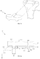
- FIGS. 1 through 6 show issues that conventional uncemented TKA present. It is understood based on the drawings that initial implant fixation with stability is difficult.
- the keel 32 provides excellent rotational stability in an conventional TKA tibial component 30 , whereas coronal stability provided by the keel is unsatisfactory due to the keel being able to lift off the bone or the keel being vulnerable to forces exerted vertically as shown in FIG. 1 . As shown in FIG. 2 , sagittal plane stability is even more challenging due to roll back.
- joint forces in the conventional femoral component are parallel to the fixation pegs and the implant may be in rocking motion, leading to bone ingrowth failure.
- FIG. 4 shows a mimetic view illustrating insertion of the conventional tibial component 30 . It can be seen from FIG. 4 that the tibia must be dislocated since the conventional tibial component 30 is loaded from the top, which complicates surgical procedures and is invasive.
- Bicruciate retaining TKA is one type of TKA where anterior cruciate ligament (ACL) is preserved.
- BCR has advantages of natural knee motion, improved range of motion (ROM), and improved joint functions.
- ROM range of motion
- a BCR tibial component is used in this case.
- an conventional BCR tibial component 300 requires creation of cruciate bone island 1000 .
- corners (indicated by arrows) on the cruciate bone island 1000 create stress risers leading to avulsion fracture.
- An object of the present invention is to provide a knee joint implant capable of resisting rotation, resisting external forces in coronal and sagittal planes, and providing stable fixing forces.
- Another object of the present invention is to provide a knee joint implant which can simplify complex surgical procedures.
- Yet another object of the present invention is to provide a knee joint implant which can minimize delay of recovery by reducing bone removal.
- Yet another object of the present invention is to provide a knee joint implant which can minimize a surgical area by being slidably inserted to a bone from a side, simplify surgical procedures, and minimize bone loss during removal in revision surgery.
- Yet another object of the present invention is to provide a knee joint implant where a tibial component can be inserted into the tibia without dislocating the femur by configuring the tibial component to be inserted from the side of the tibia.
- Yet another object of the present invention is to provide a knee joint implant comprising a tibial component having a fixing portion being insertable from the side and reduced vulnerability to vertical fixing force.
- Yet another object of the present invention is to provide a knee joint implant comprising a tibial component having resistance to pull-out from the tibia.
- Yet another object of the present invention is to provide a knee joint implant capable of improving bone ingrowth.
- Yet another object of the present invention is to provide a knee joint implant comprising a BCR tibial component being insertable from the side of the tibia.
- Yet another object of the present invention is to provide a knee joint implant comprising a BCR tibial component having a fixing portion being insertable from the side of the tibia and improving the vertical fixing force.
- Yet another object of the present invention is to provide a knee joint implant comprising a patellofemoral component having reduced vulnerability to the vertical fixing force by being inserted by slide fit.
- Yet another object of the present invention is to provide a knee joint implant comprising a patella component capable of improving bone ingrowth and being stably fixed.
- Yet another object of the present invention is to provide a knee joint implant comprising protrusion portion having parts gradually expanding and shrinking to be slidablely inserted from anterior direction or lateral-medial direction and prevent stress concentration.
- the present invention has been made in an effort to solve the problems.
- a knee joint implant comprising: a body portion including an articular surface and a contact surface formed on an opposite side of the articular surface; and a protrusion portion protruding from the contact surface and including a laterally expanded portion.
- the protrusion portion includes a first portion gradually expanding in a lateral direction and a second portion gradually shrinking in the lateral direction.
- the protrusion portion protrudes while forming a curved surface.
- the protrusion portion is a cylinder protruded from the contact surface.
- the implant is a tibial component, and the tibial component is inserted into a tibia in the lateral direction.
- the tibial component includes at least two protrusion portions, wherein the protrusion portions are formed at both sides.
- the tibial component protrudes substantially vertically from the contact surface and further comprises an extending portion disposed between the contact surface and the protrusion portion.
- the tibial component further comprises a pad disposed on an upper surface of the articular surface and made by polyethylene.
- spikes are formed on at least part of the surface of the protrusion portion.
- the implant is a femoral component, and the femoral component is inserted in a femur in the lateral direction.
- porous coating is applied to the surfaces of the contact surface and the protrusion portion.
- the femoral component further comprises a pair of protrusion portions, wherein the pair of the protrusion portions are insertable in the lateral direction into a fixing hole formed in the femur.
- the implant is a BCR tibial component, and the BCR tibial component is inserted into a tibia in the lateral direction.
- the implant further comprises a pair of BCR tibial components, wherein the pair of the BCR tibial components are insertable into fixing holes formed in the lateral and medial aspect of the tibia, respectively.
- the pair of the BCR tibial components includes a linkage buried in the tibia and connecting the pair of the BCR tibial components with each other.
- the linkage is formed as a curved shape or a V-shape.
- the implant is a patellofemoral component inserted into a femur in a direction parallel to a femoral surface.
- the present invention can obtain the following effects.
- a knee joint implant capable of resisting rotation, resisting external forces in coronal and sagittal planes, and providing stable fixing forces.
- a knee joint implant which can simplify complex surgical procedures.
- a knee joint implant which can minimize delay of recovery by reducing bone removal.
- a knee joint implant which can minimize a surgical area by being slidably inserted to a bone from a side, simplify surgical procedures, and minimize bone loss during removal in revision surgery.
- a knee joint implant where a tibial component can be inserted into the tibia without dislocating the femur by configuring the tibial component to be inserted from the side of the tibia.
- a knee joint implant comprising a tibial component having a fixing portion being insertable from the side and reduced vulnerability to vertical fixing force.
- a knee joint implant comprising a tibial component having resistance to pull-out from the tibia.
- a knee joint implant capable of improving bone ingrowth.
- a knee joint implant comprising a BCR tibial component being insertable from the side of the tibia.
- a knee joint implant comprising a BCR tibial component having a fixing portion being insertable from the side of the tibia and improving the vertical fixing force.
- a knee joint implant comprising a patellofemoral component having reduced vulnerability to the vertical fixing force by being inserted by slide fit.
- a knee joint implant comprising a patella component capable of improving bone ingrowth and being stably fixed.
- FIGS. 1 to 2 show issues that conventional TKA tibial components have
- FIG. 3 shows an issue that conventional UKA femoral components have
- FIG. 4 illustrates a top loading method of the conventional TKA tibial components
- FIGS. 5 a and 5 b show issues that the conventional TKA tibial components have in revision surgery
- FIG. 6 shows issues that conventional BCR tibial components have
- FIG. 7 a shows a view of a TKA tibial component according to one embodiment of the present invention, coupled to the tibia;
- FIG. 7 b shows an exploded perspective view of FIG. 8 a
- FIG. 8 a shows a front view of the TKA tibial component according to one embodiment of the present invention
- FIG. 8 b shows a perspective view of the TKA tibial component according to one embodiment of the present invention
- FIG. 8 c shows a bottom view of the TKA tibial component according to one embodiment of the present invention.
- FIG. 9 a shows a view of a TKA tibial component according to another embodiment of the present invention, coupled to the tibia;
- FIGS. 10 a and 10 b show a perspective view and a bottom view, respectively, of a TKA tibial component according to another embodiment of the present invention
- FIG. 11 shows a TKA tibial component according to another embodiment of the present invention.
- FIG. 12 shows a TKA tibial component according another embodiment of the present invention.
- FIG. 13 shows a mimetic view illustrating insertion of the tibial component according to the present invention into the tibia
- FIG. 14 a shows a view of a UKA femoral component according to another embodiment of the present invention, coupled to the tibia;
- FIG. 14 b shows an exploded perspective view of FIG. 17 a
- FIG. 15 a shows a perspective view of the UKA femoral component according to another embodiment of the present invention.
- FIG. 15 b shows a bottom view of the UKA femoral component according to another embodiment of the present invention.
- FIG. 15 c shows a front view of the UKA femoral component according to another embodiment of the present invention.
- FIG. 16 shows a perspective view of the UKA femoral component according to another embodiment of the present invention.
- FIG. 17 a shows a front view of a BCR tibial component according to yet another embodiment of the present invention.
- FIG. 17 b shows a top view of a BCR tibial component according to yet another embodiment of the present invention.
- FIG. 17 c shows a BCR tibial component according to yet another embodiment of the present invention, coupled to the tibia;
- FIG. 18 a shows a front view of a BCR tibial component according to yet another embodiment of the present invention.
- FIG. 18 b shows a top view of a BCR tibial component according to yet another embodiment of the present invention.
- FIG. 18 c shows a BCR tibial component according to yet another embodiment of the present invention, coupled to the tibia;
- FIG. 19 a shows a patellofemoral component according another embodiment of the present invention.
- FIG. 19 b shows an exploded perspective view of FIG. 22 a
- FIG. 20 a shows a perspective view of a patellofemoral component according to another embodiment of the present invention.
- FIG. 20 b shows a bottom view of a patellofemoral component according to another embodiment of the present invention.
- FIG. 20 c shows a front view of a patella femoral component according to another embodiment of the present invention.
- FIG. 21 a shows a perspective view of a patellofemoral component according to another embodiment of the present invention.
- FIG. 21 b shows a bottom view of a patellofemoral component according to another embodiment of the present invention.
- FIG. 22 shows a sectional view cut along A-A′ represented in FIG. 21 a.
- a knee joint implant comprises: a body portion including an articular surface and a contact surface formed in an opposite side to the articular surface; and a protrusion portion protruding from the contact surface and including a laterally expanded portion.
- the knee joint implant according to the present invention may be any one of a TKA tibial component, a TKA femoral component, a BCR component, and a patellofemoral component, etc.
- the knee joint implant is the tibial component and may be a TKA tibial component 60 .
- the TKA tibial component 60 includes: a body portion 602 having an articular surface 6002 and a contact surface 6004 formed on an opposite side of the articular surface 6002 .
- the body portion 602 replaces resected tibia 10 , and the articular surface 6002 contacts with the femur (not shown) in an upper side and corresponds to a surface on which the femur articulates with respect to the tibial component.
- the contact surface 6004 contacting the tibia 10 is formed on the opposite side of the articular surface 6002 .
- the TKA tibial component 60 includes a protrusion portion 604 protruding from the contact surface 6004 and including a laterally expanded part.
- two or more protrusions 604 may be formed at both sides.
- the protrusion portion 604 is a portion which protrudes from the contact surface 6004 and is inserted in the bone.
- the protrusion portion 604 has a part where its width expands.
- the protrusion portion 604 forms a curved surface and protrudes from the contact surface 6004 .
- the protrusion portion 604 may comprise a first portion 1604 protruding from the contact surface 6004 and gradually expanding in the lateral direction; and a second portion 1606 protruding from the first portion 1604 and gradually shrinking in the lateral direction.
- the lateral direction means a lateral L-medial M line of the tibia
- the width of the protrusion portion 604 may be expanded in the L-M direction of the tibia. Accordingly, the TKA tibial component 60 may be inserted from the anterior aspect, not using the top loading method of the conventional tibia component as described above.
- protrusion portion 604 is elongated and is integrally formed with and extends from contact surface 6004 .
- Protrusion portion 604 has opposing side faces 610 and 612 that extend longitudinally along contact surface 6004 between opposing end faces 614 and 616 (see FIG. 10 b ) and that outwardly project from contact surface 6004 to an outer face 618 .
- Opposing side faces 610 and 612 are curved and extend linearly between opposing end faces 614 and 616 .
- Opposing end faces 614 and 616 of protrusion portion 604 are openly exposed.
- Protrusion portion 604 has a height H that extends between contact surface 6004 and outer face 618 and a width W that extends between the opposing side faces 610 and 612 along height H.
- Protrusion portion 604 has first portion 1604 wherein width W of protrusion portion 604 gradually laterally expands as protrusion portion 604 projects away from contact surface 6004 along a first section of height H.
- the width W of second portion 1606 of protrusion portion 604 gradually laterally constricts along a second section of height H, first portion 1604 being disposed between contact surface 6004 and second portion 1606 .
- Protrusion portion 604 is freely disposed on contact surface 6004 so that no protrusions outwardly project from contact surface 6004 and intersect with protrusion portion 604 .
- the width of the protrusion portion 604 may be expanded as the protrusion portion 604 protrudes from the body portion 602 and then shrunk.
- the protrusion portion 604 may be a cylinder or an elliptic cylinder protruding from the contact surface 6004 . That is, the cross section of the protrusion portion 604 may be circular or elliptical and may take other shapes if the shape includes the first portion 1604 gradually expanding in the lateral direction and the second portion 1606 protruding from the first portion 1604 and gradually shrinking in the lateral direction.
- a hole having a shape complementary to the protrusion portion 604 in the tibia, and the TKA tibial component 60 according to the present invention is inserted in the tibia by being inserted from the anterior aspect of the tibia. Accordingly, as the TKA tibial component 60 takes a lateral insertion method, not the top loading method of prior art, pull out strength of the tibial component is improved and stable fixing forces are provided.
- the protrusion portion 604 may have various shapes if the protrusion portion 604 retains a region of increasing width as the protrusion portion 604 protrudes outward from the body portion 602 . As shown in the drawings, it is preferable to form the protrusion portion as a cylinder. In case of a triangle or a dovetail shape, forming a fixing groove complementary to such shape during bone removal for inserting the protrusion portion 604 may be challenging, and stress may be concentrated on the bone as edged parts act as a notch or the bone may fracture. However, according to the present invention, since the cross section of the protrusion portion 604 is formed to have a curved surface, such as a circle, notches are not present and, thus, stress concentrations and bone fracture are prevented.
- the TKA tibial component 60 is inserted from the anterior aspect or the posterior aspect, which means the TKA tibial component 60 is not loaded from the top of the tibia.
- the TKA tibial component 60 is configured to be inserted in a horizontal direction. Accordingly, unlike the conventional tibial component, the protrusion portion 602 provides excellent resistance to vertically exerted forces and vertical fixing forces against force applied on the joint.
- contact surface 6004 and the protrusion portion 604 may be applied with porous coating, which induces bone ingrowth.
- the protrusion portion 606 may include spikes S which extends from anterior side to posterior side and are formed on at least part of the surfaces.
- the spikes S may be formed on at least part of the surface of the protrusion portion 606 and on the entire surface of the protrusion portion 606 .
- the spikes increase surface area of the protrusion portion 606 contacting the tibia and improves initial fixing force.
- the TKA tibial component according to still another embodiment of the present invention further comprises an extending portion 610 disposed between the contact surface 6004 of the body portion 602 and the protrusion portions having a first portion 604 and a second portion 606 .
- the extending portion 610 protrudes from the contact surface 6004 substantially perpendicularly and extends to a top surface of the first portion 604 gradually expanding in the lateral direction. Since the extending portion 610 moves fixing points away from the surface of the tibia, initial fixation can be improved.
- the pullout strength of the tibia component 60 can be improved if the extending portion 610 lengthens.
- the TKA tibial component further comprises a pad 608 disposed on an upper surface of the articular surface 6002 of the body portion 602 as shown in FIG. 12 .
- the pad 608 includes an upper face acting as an articular surface, and the material may preferably be polyethylene.
- polishing of the body portion 602 and cross-linked polyethylene pad 608 may be used to improve coupling with the pad 608 .
- FIG. 13 shows a mimetic view illustrating insertion of the tibial component 60 according to the present invention.
- the shape of the tibial component according to the present invention is suited to be slidingly inserted from anterior to posterior sides.
- the tibial component 60 can be inserted from the anterior side of the tibia without separating the tibia and the femur for access to an upper portion of the tibia.
- preservation of cruciate ligaments is facilitated and a surgical area is minimized.
- the knee joint implant according to another embodiment of the present invention is the femoral component and may be any of the TKA femoral component and the UKA femoral component. Below the UKA femoral component 80 is described as an example.
- the UKA femoral component 80 includes: a body portion 802 having an articular surface 8002 and a contact surface 8004 formed on an opposite side of the articular surface 8002 .
- the body portion 802 replaces resected tibia 10 , and the articular surface 8002 contacts with the tibia (not shown) in a lower side and corresponds to a surface on which the femur articulates with respect to the tibial component.
- the contact surface 8004 contacting the femur 20 is formed.
- the UKA femoral component 80 includes a protrusion portion 804 protruding from the contact surface 6004 and including a laterally expanded part.
- two or more protrusion portions may be formed at both sides.
- the protrusion portion 804 is a portion which protrudes from the contact surface 8004 and is inserted in the bone.
- the protrusion portion 804 has a part where its width expands.
- the protrusion portion 804 forms a curved surface and protrudes from the contact surface 8004 .
- the protrusion portion 804 may comprise a first portion 1804 protruding from the contact surface 8004 and gradually expanding in the lateral direction; and a second portion 1806 protruding from the first portion 1804 and gradually shrinking in the lateral direction.
- the later direction means a direction perpendicular to the protruding direction of the protrusion portion 804 from the contact surface 8004 .
- the width of the protrusion portion 804 may be expanded as the protrusion portion 804 protrudes from the body portion 802 and then shrunk.
- the protrusion portion 804 may be a cylinder or an elliptic cylinder protruding from the contact surface 8004 . That is, the cross section of the protrusion portion 804 may be circular or elliptical and may take other shapes if the shape includes the first portion 1804 gradually expanding in the lateral direction and the second portion 1806 protruding from the first portion 1804 and gradually shrinking in the lateral direction.
- a hole having a shape complementary to the protrusion portion 804 in the femur, and the UKA femoral component 80 according to the present invention is inserted from the lateral or medial aspect of the femur. Accordingly, as the UKA femoral component 80 takes a lateral insertion method, pull out strength of the femoral component is improved and stable fixing forces are provided.
- the protrusion portion 804 may have various shapes if the protrusion portion 804 retains a region of increasing width as the protrusion portion 804 protrudes outward from the body portion 802 . As shown in the drawings, it is preferable to form the protrusion portion as a cylinder. In case of a triangle or a dovetail shape, forming a fixing groove complementary to such shape during bone removal for inserting the protrusion portion 804 may be challenging, and stress may be concentrated on the bone as cornered parts act as a notch or the bone may fracture. However, according to the present invention, since the cross section of the protrusion portion 804 is formed to have a curved surface, such as a circle, notches are not present and, thus, stress concentrations and bone fracture are prevented.
- the UKA femoral component 80 is inserted from the lateral or medial aspect.
- the UKA femoral component 80 is configured to be inserted in a horizontal direction.
- the protrusion portion 804 provides excellent resistance to vertically exerted forces and vertical fixing forces against force applied on the joint, and sufficient stability against rocking forces.
- rocking motion occurs during roll back, the protrusion portion 804 provides resistance, thereby maintaining a stably fixed state.
- the UKA femoral component 80 according to the present invention is inserted from the lateral or medial aspect, a resection area is small during surgery and the surgery is made simpler.
- the protrusion portion 804 may include spikes formed on at least part of the surfaces.
- the spikes are formed for stable fixation. Specifically, the spikes improve coronal plane stability and provide resistance to rocking motion.
- the UKA femoral component 80 according to another embodiment of the present invention further comprise a coating layer 806 .
- the coating layer 806 is a porous coating layer capable of improving bone ingrowth.
- the coating layer 806 is preferably applied to the contact surface 8004 and the protrusion portion 804 .
- Cobalt-chromium with the beaded surface on the backside of implant may be least expensive and have a proven track record.
- titanium with titanium oxide surface may be considered, but oxide coating should be approximately 100 ⁇ m thick to avoid chipping concerns in this case.
- cobalt-chromium with titanium plasma sprayed backside surface may be taken into consideration, but the possibility of surface delamination must be eliminated if this option is selected.
- the knee joint implant according to another embodiment of the present invention is the BCR tibial component 90 of the TKA tibial component.
- the BCR tibial component 90 includes: a body portion having an articular surface and a contact surface formed on an opposite side of the articular surface, and a linkage 902 connecting the body portion and buried in the tibia 10 , and a protrusion portion.
- the linkage 902 is formed to be buried in the tibia 10 such that the cruciate bone island extends from the posterior aspect to the anterior aspect of the tibia 10 .
- the linkage may be a linkage 902 having a curved or arc shape.
- the dimensions of the linkage 902 buried in the tibia 10 may be determined based on required connection strength.
- the linkage 902 is buried in the tibia 10 such that the cruciate bone island 1000 extends from the posterior to the anterior aspects
- stress risers at the corners are problematic as the cruciate bone island 1000 is not formed from the anterior aspect to the posterior aspect but formed partly along the anterior to posterior tibia in prior art.
- the cruciate bone island 1000 extends from the posterior aspect to the anterior aspect of the tibia 10 , thereby resolving the issue that the conventional implant presents. Accordingly, formation of the stress risers at the corners is avoided and avulsion fracture can be prevented.
- the linkage may be a linkage 904 having a V-shape.
- the dimensions of the linkage 904 buried in the tibia 10 may be determined based on required connection strength.
- the linkage 904 is buried in the tibia 10 such that the cruciate bone island 1000 extends from the posterior to the anterior aspects. Accordingly, formation of the stress risers at the corners is prevented and avulsion fracture can be avoided.
- the BCR tibia component 90 can be inserted from the anterior side of the tibia without separating the tibia and the femur for access to an upper portion of the tibia.
- preservation of cruciate ligaments is facilitated and a surgical area is minimized.
- the problem of stress risers at sharp corners occurring in using the conventional BCR tibial component can be resolved.
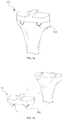
- the knee joint implant according to another embodiment of the present invention is the patellofemoral component 100 .
- the patellofemoral component 100 includes: a body portion 1002 having an articular surface 10002 and a contact surface 10004 formed on an opposite side of the articular surface 1002 .
- the body portion 1002 replaces resected femur 20
- the articular surface 10002 corresponds to a surface on which the femur articulates with respect to the patella.
- the contact surface 10004 contacting the femur 20 is formed.
- the patellofemoral component 100 includes a protrusion portion 1004 protruding from the contact surface 10004 and including a laterally expanded part.
- the protrusion portion 1004 is a portion which protrudes from the contact surface 10004 and is inserted in the bone.
- the protrusion portion 1004 has a part where its width expands.
- the protrusion portion 1004 forms a curved surface and protrudes from the contact surface 10004 .
- the protrusion portion 1004 may comprise a first portion 11004 protruding from the contact surface 10004 and gradually expanding in the lateral direction; and a second portion 11006 protruding from the first portion 11004 and gradually shrinking in the lateral direction.
- the width of the protrusion portion 1004 may be expanded as the protrusion portion 1004 protrudes from the body portion 1002 and then shrunk.
- the protrusion portion 1004 may be a cylinder or an elliptic cylinder protruding from the contact surface 10004 . That is, the cross section of the protrusion portion 1004 may be circular or elliptical and may take other shapes if the shape includes the first portion 11004 gradually expanding in the lateral direction and the second portion 11006 protruding from the first portion 11004 and gradually shrinking in the lateral direction.
- a hole having a shape complementary to the protrusion portion 1004 is formed in the femur 20 , and the patellofemoral component 100 according to the present invention is inserted in the femur 20 by being inserted from the distal femur. Accordingly, as the patellofemoral component 100 is slidingly fit in the femur, pull out strength of the tibial component is improved and stable fixing forces are provided.
- the protrusion portion 1004 may have various shapes if the protrusion portion 1004 retains a region of increasing width as the protrusion portion 1004 protrudes outward from the body portion 1002 . As shown in the drawings, it is preferable to form the protrusion portion as a cylinder. In case of a triangle or a dovetail shape, forming a fixing groove complementary to such shape during bone removal for inserting the protrusion portion 1004 may be challenging, and stress may be concentrated on the bone as cornered parts act as a notch or the bone may fracture. However, according to the present invention, since the cross section of the protrusion portion 1004 is formed to have a curved surface, such as a circle, notches are not present and, thus, stress concentrations and bone fracture are prevented.
- the protrusion portion 1004 since a center part of the protrusion portion 1004 in the vertical direction is expanded the most, stable fixing forces are provided with respect to the femur 20 . As shown in FIG. 22 b , the patellofemoral component 100 is inserted along a direction parallel to the longitudinal cross section of the femur. Accordingly, the protrusion portion 1004 provides excellent resistance to vertically exerted forces and vertical fixing forces against force applied on the joint.
- the knee joint implant according to the embodiments of the present invention provides stable fixation due to its shape. Also, the unique implant insertion method minimizes surgical areas and simplifies surgical procedures. Furthermore, bone removal can be reduced in knee joint implant surgery according to the present invention.
- a patella component 110 may comprise: an articular surface 1112 and a support portion 1114 .
- the articular surface 1112 articulates with respect to the femur 20 and may be formed by polyethylene. Although conventional patella components are made entirely by polyethylene, only the articular surface 1112 at the outer side are made by polyethylene in the patella component 110 according to the present invention. Preferably, the thickness of the articular surface 1112 is 4-5 mm. Cross-linked polyethylene may be used as a material for the articular surface 1112 , but this may cause a structural problem. Thus, it is preferable to use ethylene oxide sterilization.
- the support portion 114 disposed inside the articular surface 1112 is coupled to the patella and includes one or more legs 1116 for coupling with the patella.
- the support portion 1114 is made by a metal, not polyethylene as in the conventional patella component. Also, a porous structure is formed on a coupling surface coupled to the patella, thereby inducing bone ingrowth and stable fixation.
- the contour of the support portion 1114 is configured to correspond to the contour of the articular surface 1112 . This removes stress risers and sufficiently supports the entire polyethylene.
Landscapes
- Health & Medical Sciences (AREA)
- Orthopedic Medicine & Surgery (AREA)
- Life Sciences & Earth Sciences (AREA)
- Transplantation (AREA)
- General Health & Medical Sciences (AREA)
- Veterinary Medicine (AREA)
- Engineering & Computer Science (AREA)
- Biomedical Technology (AREA)
- Heart & Thoracic Surgery (AREA)
- Oral & Maxillofacial Surgery (AREA)
- Animal Behavior & Ethology (AREA)
- Public Health (AREA)
- Physical Education & Sports Medicine (AREA)
- Surgery (AREA)
- Cardiology (AREA)
- Vascular Medicine (AREA)
- Dentistry (AREA)
- Nuclear Medicine, Radiotherapy & Molecular Imaging (AREA)
- Medical Informatics (AREA)
- Molecular Biology (AREA)
- Prostheses (AREA)
- Surgical Instruments (AREA)
Abstract
Description
-
- 10: tibia
- 20: femur
- 30, 60: TKA tibial component
- 32: keel
- 50, 80: UKA femoral component
- 90, 300: BCR tibial component
- 100: patellofemoral component
- 110: patella component
- 602, 702, 802, 902, 1002: body portion
- 604, 606, 704, 804, 904, 1004: protrusion portion
- 608: pad
- 610: extending portion
- 806: coating layer
- 902, 904: linkage
- 1000: cruciate bone island
- 1112, 6002, 7002, 8002, 9002, 10002: articular surface
- 1114: support portion
- 1116: leg
- 6004, 7004, 8004, 9004, 10004: contact surface
Claims (10)
Priority Applications (1)
| Application Number | Priority Date | Filing Date | Title |
|---|---|---|---|
| US15/720,773 US11090164B2 (en) | 2016-10-12 | 2017-09-29 | Knee joint implant |
Applications Claiming Priority (2)
| Application Number | Priority Date | Filing Date | Title |
|---|---|---|---|
| US201662407316P | 2016-10-12 | 2016-10-12 | |
| US15/720,773 US11090164B2 (en) | 2016-10-12 | 2017-09-29 | Knee joint implant |
Publications (2)
| Publication Number | Publication Date |
|---|---|
| US20180098857A1 US20180098857A1 (en) | 2018-04-12 |
| US11090164B2 true US11090164B2 (en) | 2021-08-17 |
Family
ID=61829776
Family Applications (2)
| Application Number | Title | Priority Date | Filing Date |
|---|---|---|---|
| US15/720,773 Active 2038-12-20 US11090164B2 (en) | 2016-10-12 | 2017-09-29 | Knee joint implant |
| US15/720,820 Active 2038-07-10 US10751189B2 (en) | 2016-10-12 | 2017-09-29 | Resection guide, trial knee joint implant, and surgical instrument for knee arthroplasty |
Family Applications After (1)
| Application Number | Title | Priority Date | Filing Date |
|---|---|---|---|
| US15/720,820 Active 2038-07-10 US10751189B2 (en) | 2016-10-12 | 2017-09-29 | Resection guide, trial knee joint implant, and surgical instrument for knee arthroplasty |
Country Status (1)
| Country | Link |
|---|---|
| US (2) | US11090164B2 (en) |
Families Citing this family (6)
| Publication number | Priority date | Publication date | Assignee | Title |
|---|---|---|---|---|
| KR102162651B1 (en) * | 2018-07-10 | 2020-10-08 | 주식회사 코렌텍 | Gap Gauge to check the Flexion Gap before Posterior Cutting |
| EP4031026A1 (en) * | 2019-09-19 | 2022-07-27 | Engage Uni LLC | Unicompartmental knee arthroplasty |
| CN111329626B (en) * | 2020-03-09 | 2022-04-12 | 中南大学湘雅医院 | Knee joint spacer and preparation method thereof |
| CN111759442B (en) * | 2020-06-18 | 2021-04-20 | 夏磊 | Pedicle screw placing guide clamp |
| CN113397769B (en) * | 2021-07-21 | 2022-06-10 | 北京力达康科技有限公司 | Combined anti-falling knee joint prosthesis |
| WO2025171266A1 (en) * | 2024-02-09 | 2025-08-14 | Ignite Orthomotion, Llc | Implants, systems and methods of using the same |
Citations (16)
| Publication number | Priority date | Publication date | Assignee | Title |
|---|---|---|---|---|
| US4211228A (en) | 1979-01-24 | 1980-07-08 | Cloutier Jean Marie | Multipurpose tibial template |
| US5037423A (en) | 1983-10-26 | 1991-08-06 | Pfizer Hospital Products Group, Inc. | Method and instrumentation for the replacement of a knee prosthesis |
| US6102954A (en) * | 1992-05-18 | 2000-08-15 | Astra Aktiebolag | Joint prosthesis and apparatus for preparing the bone prior to fitting of the prosthesis |
| US20020198530A1 (en) | 2001-06-20 | 2002-12-26 | Sanford Adam H. | Method and apparatus for resecting a distal femur and a proximal tibia in preparation for implanting a partial knee prosthesis |
| US20040097951A1 (en) | 2002-11-18 | 2004-05-20 | Steffensmeier Scott J. | Measurement instrument for use in orthopaedic surgery |
| WO2005051240A1 (en) * | 2003-11-25 | 2005-06-09 | Conformis, Inc. | Patient selectable knee joint arthroplasty devices |
| US20060111726A1 (en) | 2002-07-11 | 2006-05-25 | Advanced Bio Surfaces, Inc. | Method and kit for interpositional arthroplasty |
| US7094241B2 (en) | 2002-11-27 | 2006-08-22 | Zimmer Technology, Inc. | Method and apparatus for achieving correct limb alignment in unicondylar knee arthroplasty |
| US20100249788A1 (en) | 2009-03-26 | 2010-09-30 | Martin Roche | System and method for orthopedic distraction and stabilization |
| US20110004316A1 (en) | 2009-07-01 | 2011-01-06 | David Murray | Method of Implanting a Unicondylar Knee Prosthesis |
| US8167888B2 (en) | 2004-08-06 | 2012-05-01 | Zimmer Technology, Inc. | Tibial spacer blocks and femoral cutting guide |
| US20120116524A1 (en) * | 2010-05-03 | 2012-05-10 | New York University | Early intervention knee implant device and methods |
| US20120259335A1 (en) | 2005-05-20 | 2012-10-11 | Smith & Nephew, Inc. | Patello-femoral joint implant and instrumentation |
| US20130035694A1 (en) | 2011-08-01 | 2013-02-07 | Zimmer, Inc. | Combination ligament tensioner and alignment device |
| US20150374386A1 (en) | 2013-02-25 | 2015-12-31 | Stryker Corporation | Anatomically guided instrumentation for trochlear groove replacement |
| US20160008136A1 (en) * | 2014-07-08 | 2016-01-14 | Zimmer, Inc. | Intercondylar component and fin attachment features for use in knee arthroplasty |
-
2017
- 2017-09-29 US US15/720,773 patent/US11090164B2/en active Active
- 2017-09-29 US US15/720,820 patent/US10751189B2/en active Active
Patent Citations (16)
| Publication number | Priority date | Publication date | Assignee | Title |
|---|---|---|---|---|
| US4211228A (en) | 1979-01-24 | 1980-07-08 | Cloutier Jean Marie | Multipurpose tibial template |
| US5037423A (en) | 1983-10-26 | 1991-08-06 | Pfizer Hospital Products Group, Inc. | Method and instrumentation for the replacement of a knee prosthesis |
| US6102954A (en) * | 1992-05-18 | 2000-08-15 | Astra Aktiebolag | Joint prosthesis and apparatus for preparing the bone prior to fitting of the prosthesis |
| US20020198530A1 (en) | 2001-06-20 | 2002-12-26 | Sanford Adam H. | Method and apparatus for resecting a distal femur and a proximal tibia in preparation for implanting a partial knee prosthesis |
| US20060111726A1 (en) | 2002-07-11 | 2006-05-25 | Advanced Bio Surfaces, Inc. | Method and kit for interpositional arthroplasty |
| US20040097951A1 (en) | 2002-11-18 | 2004-05-20 | Steffensmeier Scott J. | Measurement instrument for use in orthopaedic surgery |
| US7094241B2 (en) | 2002-11-27 | 2006-08-22 | Zimmer Technology, Inc. | Method and apparatus for achieving correct limb alignment in unicondylar knee arthroplasty |
| WO2005051240A1 (en) * | 2003-11-25 | 2005-06-09 | Conformis, Inc. | Patient selectable knee joint arthroplasty devices |
| US8167888B2 (en) | 2004-08-06 | 2012-05-01 | Zimmer Technology, Inc. | Tibial spacer blocks and femoral cutting guide |
| US20120259335A1 (en) | 2005-05-20 | 2012-10-11 | Smith & Nephew, Inc. | Patello-femoral joint implant and instrumentation |
| US20100249788A1 (en) | 2009-03-26 | 2010-09-30 | Martin Roche | System and method for orthopedic distraction and stabilization |
| US20110004316A1 (en) | 2009-07-01 | 2011-01-06 | David Murray | Method of Implanting a Unicondylar Knee Prosthesis |
| US20120116524A1 (en) * | 2010-05-03 | 2012-05-10 | New York University | Early intervention knee implant device and methods |
| US20130035694A1 (en) | 2011-08-01 | 2013-02-07 | Zimmer, Inc. | Combination ligament tensioner and alignment device |
| US20150374386A1 (en) | 2013-02-25 | 2015-12-31 | Stryker Corporation | Anatomically guided instrumentation for trochlear groove replacement |
| US20160008136A1 (en) * | 2014-07-08 | 2016-01-14 | Zimmer, Inc. | Intercondylar component and fin attachment features for use in knee arthroplasty |
Also Published As
| Publication number | Publication date |
|---|---|
| US20180098857A1 (en) | 2018-04-12 |
| US20180098773A1 (en) | 2018-04-12 |
| US10751189B2 (en) | 2020-08-25 |
Similar Documents
| Publication | Publication Date | Title |
|---|---|---|
| US12150860B2 (en) | Cruciate-retaining knee prosthesis | |
| US11090164B2 (en) | Knee joint implant | |
| US10413415B2 (en) | Motion facilitating tibial components for a knee prosthesis | |
| CN110731837B (en) | Ligament remains type shin bone tumour matched stack formula half knee joint prosthesis | |
| CA2542619C (en) | High flexion articular insert | |
| EP1974693B1 (en) | Mobile tibial bearing assembly | |
| US20220346963A1 (en) | Knee joint prosthesis and tibial component thereof | |
| US10076419B2 (en) | Method of implanting a unicondylar knee prosthesis | |
| JP2008253771A (en) | Mobile bearing assembly | |
| CN107661161A (en) | Total knee implants prosthesis assembly and method | |
| US8114164B2 (en) | Bicondylar resurfacing prosthesis and method for insertion through direct lateral approach | |
| CA2924694C (en) | Reverse knee prosthesis | |
| US10524920B2 (en) | Prosthesis with fixed or mobile bearing | |
| US20200093604A1 (en) | Modular knee prosthesis | |
| US10182915B2 (en) | Cartilage prosthetic implant | |
| US20140200674A1 (en) | Knee replacement prosthetic | |
| JP7618583B2 (en) | Orthopedic implant system with bone preservation function |
Legal Events
| Date | Code | Title | Description |
|---|---|---|---|
| AS | Assignment |
Owner name: CORENTEC CO., LTD, KOREA, REPUBLIC OF Free format text: ASSIGNMENT OF ASSIGNORS INTEREST;ASSIGNORS:SHARKEY, PETER F.;PARVIZI, JAVAD;REEL/FRAME:043743/0963 Effective date: 20170927 |
|
| FEPP | Fee payment procedure |
Free format text: ENTITY STATUS SET TO UNDISCOUNTED (ORIGINAL EVENT CODE: BIG.); ENTITY STATUS OF PATENT OWNER: SMALL ENTITY |
|
| FEPP | Fee payment procedure |
Free format text: ENTITY STATUS SET TO SMALL (ORIGINAL EVENT CODE: SMAL); ENTITY STATUS OF PATENT OWNER: SMALL ENTITY |
|
| STPP | Information on status: patent application and granting procedure in general |
Free format text: DOCKETED NEW CASE - READY FOR EXAMINATION |
|
| STPP | Information on status: patent application and granting procedure in general |
Free format text: NON FINAL ACTION MAILED |
|
| STPP | Information on status: patent application and granting procedure in general |
Free format text: RESPONSE TO NON-FINAL OFFICE ACTION ENTERED AND FORWARDED TO EXAMINER |
|
| STPP | Information on status: patent application and granting procedure in general |
Free format text: NON FINAL ACTION MAILED |
|
| STPP | Information on status: patent application and granting procedure in general |
Free format text: FINAL REJECTION MAILED |
|
| STPP | Information on status: patent application and granting procedure in general |
Free format text: DOCKETED NEW CASE - READY FOR EXAMINATION |
|
| STPP | Information on status: patent application and granting procedure in general |
Free format text: NOTICE OF ALLOWANCE MAILED -- APPLICATION RECEIVED IN OFFICE OF PUBLICATIONS |
|
| STPP | Information on status: patent application and granting procedure in general |
Free format text: PUBLICATIONS -- ISSUE FEE PAYMENT RECEIVED |
|
| STPP | Information on status: patent application and granting procedure in general |
Free format text: PUBLICATIONS -- ISSUE FEE PAYMENT VERIFIED |
|
| STCF | Information on status: patent grant |
Free format text: PATENTED CASE |
|
| MAFP | Maintenance fee payment |
Free format text: PAYMENT OF MAINTENANCE FEE, 4TH YR, SMALL ENTITY (ORIGINAL EVENT CODE: M2551); ENTITY STATUS OF PATENT OWNER: SMALL ENTITY Year of fee payment: 4 |