EP1523085A2 - Enclosed electrical machine and method to design such a machine - Google Patents
Enclosed electrical machine and method to design such a machine Download PDFInfo
- Publication number
- EP1523085A2 EP1523085A2 EP04450187A EP04450187A EP1523085A2 EP 1523085 A2 EP1523085 A2 EP 1523085A2 EP 04450187 A EP04450187 A EP 04450187A EP 04450187 A EP04450187 A EP 04450187A EP 1523085 A2 EP1523085 A2 EP 1523085A2
- Authority
- EP
- European Patent Office
- Prior art keywords
- machine
- cooling fins
- nodes
- electrical machine
- stator
- Prior art date
- Legal status (The legal status is an assumption and is not a legal conclusion. Google has not performed a legal analysis and makes no representation as to the accuracy of the status listed.)
- Withdrawn
Links
Images


Classifications
-
- H—ELECTRICITY
- H02—GENERATION; CONVERSION OR DISTRIBUTION OF ELECTRIC POWER
- H02K—DYNAMO-ELECTRIC MACHINES
- H02K5/00—Casings; Enclosures; Supports
- H02K5/04—Casings or enclosures characterised by the shape, form or construction thereof
- H02K5/18—Casings or enclosures characterised by the shape, form or construction thereof with ribs or fins for improving heat transfer
-
- H—ELECTRICITY
- H02—GENERATION; CONVERSION OR DISTRIBUTION OF ELECTRIC POWER
- H02K—DYNAMO-ELECTRIC MACHINES
- H02K5/00—Casings; Enclosures; Supports
- H02K5/04—Casings or enclosures characterised by the shape, form or construction thereof
- H02K5/06—Cast metal casings
Definitions
- the invention relates to an encapsulated electrical machine, preferably vertically installed asynchronous traction machine, with a housing, a stator arranged in the housing and a rotating one Shaft with a rotor attached to it, the machine optionally for assembly with a gearbox is provided, wherein the bearing takes place on the transmission side.
- Electric motors for driving vehicles must be as close as possible be possible on the driven axle to complicated and expensive To bypass power transmissions.
- the tons heavier Rail vehicles can only drive the electric drive motors directly be arranged in the bogie. At every turn and even when driving straight ahead, there are large relative movements between the bogie and car body, the power transmission in an arrangement the drive motor outside the bogie constantly would have to compensate.
- the bogie is but directly above the rails or over the floor.
- the usual fürzugsbel hereeten motors can therefore through the wind very easily foreign objects, such as pebbles, Dust or rain water with the cooling air into the engine and damage it, leaving it prematurely after a short operating time fails. That is why rail vehicles are almost exclusive closed or encapsulated motors are used.
- the bogie also houses the suspension and brakes, so that there is hardly enough space for the drive motors is.
- the object of the invention is therefore to provide a machine of the aforementioned Kind of creating, on the one hand, the above disadvantages avoids and on the other hand constructively the given space conditions can be adjusted in the driven vehicle.
- Another object of the present invention is the Creation of a method for the interpretation of one of the above electrical machine through which the real conditions in the Operation of the electric machine can be considered and thus the machine optimally adapted to the respective application can be.
- the first electrical machine according to the invention is characterized that the dissipation of heat loss through natural convection or radiation and optionally by one of the airstream produced convection, wherein the housing made of light metal, preferably aluminum, is made and the housing outside, diagonally opposite, cooling fins has.
- the cooling fins are arranged so that the existing space is used optimally.
- the necessary for cooling Surface of the cooling fins to be arranged is about one, later calculated, computation or data processing program calculated.
- the calculated and required for cooling surface can then be transferred to the number and dimensions of the cooling fins.
- the cooling fins can then be structurally arranged so that on the one hand the calculated surface is reached and on the other hand the installation conditions is taken into account.
- Another advantage of this enclosed machine is to be seen in that they are independent of the quality or quality of the ambient air is. Both heavily polluted street air, but also Pebbles or splash water do not penetrate into the machine interior one. Furthermore, the machine according to the invention has the advantage that by the use of light metal, in particular aluminum, a weight saving of over 30% compared to conventional cast steel versions is reached. The use of, for example Aluminum also has the advantage of less inspection and maintenance on the engine, since aluminum does not rust.
- the cooling fins are preferably made excessively, i. point a length which is a multiple of the thickness of the cooling fins and the distances of the cooling fins to each other is.
- a really surprising advantage is the overlong cooling fins, because on the one hand, despite the encapsulation of the machine, the surface create for the necessary cooling and on the other hand the Do not increase the external dimensions of the machine disproportionately. This in turn is due to the use of aluminum, because aluminum has a 10 times better thermal conductivity as a cast steel. Due to this excellent thermal conductivity The overlong cooling fins are only really effective thermally.
- the cooling fins are vertical, i. paraxial, arranged.
- Such traction machines mainly for a single-wheel drive which are installed with a vertical shaft, This is the type of construction of the cooling fins a very large surface created for heat dissipation by convection.
- This design of the cooling fins is a maximum cooling surface achieved with minimal space requirements.
- the alignment diagonally opposite cooling fins with each other This will be the given installation conditions in a drive portal optimal exploited.
- the arrangement takes place and / or shaping the cooling fins according to the installation and / or space.
- the Installation conditions usually specified. With this advantageous embodiment can be taken into account these requirements.
- cooling fins in particular one side of the machine, in the area their free ends connected via a jacket or webs.
- baffles od are in vertical, built-in Machine in the area just above the upper end shield or the cooling fins od baffles od. Like. Provided. By a smart Arrangement of baffles o. The like. Can be a suction flow be reached above the machine, whereby the heat dissipation still can be increased.
- a data processing program provided for the determination of state variables, in particular the Temperatures and heat flows, for the stationary final state and / or for dynamic driving, in the electric machine serves, this Daien kausprogramms the calculations via a heat source network.
- a data processing program Can be tailored to customer needs or on the space available for the installation and a economic solution to be worked out.
- the second object of the invention is achieved by a method for Design of an above-mentioned electric machine solved, wherein using a data processing program according to the geometric Definition of the machine, such as dimensions, groove shape, winding type and material properties created a heat source network is set, nodes for the heat source network and between defines the node thermal transient resistances and in the nodes the temperatures for the stationary Final state of the machine can be calculated, the temperatures in the nodes for the dynamic state of the machine be calculated by adding in the calculation the losses for the individual Nodes and / or thermal contact resistance between the individual nodes the dynamic behavior of the Machine in operation, especially the driving game, considered is, with the thermal contact resistance between the individual Nodes through the thermal capacities of the corresponding Regions of the machine are supplemented.
- a data processing program according to the geometric Definition of the machine, such as dimensions, groove shape, winding type and material properties created a heat source network is set, nodes for the heat source network and between defines the node thermal transient resistances and in the nodes the temperatures for the stationary Final state
- Limit value of the temperature for the design of the electrical machine used are now called Limit value of the temperature for the design of the electrical machine used. Are the occurring in the respective nodes maximum temperatures below the limits, the Machine can be made smaller, for example. Is the temperature above the permissible limits, the machine must be larger be executed.
- the losses such as stator, rotor, iron and additional losses as well as the mechanical losses, taken into account become.
- the adjacent structural parts such as the Housing with the cooling fins, at least one other node and the transition resistance occurring between the nodes calculated.
- the invention is in the rotor yoke and the adjacent structural parts, such as the shaft, set at least one other node and the between the Junctions occurring contact resistance calculated. Also a such node leads to the limits of the machine. A conscious approach to the limits of a machine leads usually to an optimal, so smaller, construction.
- the traction machine is burdened by the stop / go operation, so alternating loads suspended. Around Alternating loads for the calculation in reasonable values to seize Simulations can be performed and mean values taken from them. For example, from the actual driving game in the In the course of the dynamic calculation, the temperature profiles are calculated.
- the machine 1 is an encapsulated electrical machine 1 with mounted gearbox 2 as a motor-gear unit in cross section shown, which unit designed for traction operation is.
- unit designed for traction operation such Units, for example trams as a single-wheel drive, used.
- single wheel drives are in the portals of Bogies provided.
- the machine 1 has no active ventilation or additional cooling media.
- the dissipation of heat loss occurs by natural convection or radiation and optionally by a generated by the wind Convection, wherein the machine housing made of light metal, preferably Aluminum, is made and outside, diagonally opposite, has overlong cooling fins 3, on the later will be discussed in more detail.
- the machine housing made of light metal, preferably Aluminum, is made and outside, diagonally opposite, has overlong cooling fins 3, on the later will be discussed in more detail.
- the necessary for the cooling surface of the arranged cooling fins 3 is about a, later described, computer or data processing program calculated.
- the calculated for cooling and required surface can then be limited to the number and dimensions of Cooling fins 3 are transferred.
- the overlong cooling fins 3 can then constructively arranged so that on the one hand the calculated Surface is achieved and on the other hand, the installation conditions Account is taken.
- the machine 1 consists of a stator 4 and a, on a rotating shaft 5 fixed, rotor 6. Both the stator 4, as well as the rotor 6 are made of individual, assembled into laminated cores, Built up sheets.
- the stator 4 consists of stamped stator laminations, which laminated to the laminated stator core become. Furthermore, in the stator 4, the stator winding with the side outstanding winding heads 7 are arranged.
- the rotor 6 is also made from stamped rotor laminations which are laminated to the rotor core be and has the rotor winding with the shorting rings. 8 on.
- the shaft 5 of the machine 1 is designed such that that the stub shaft 9 of the transmission 2 is connected to the shaft 5 can be. This can be done via a positive and / or non-positive connection respectively.
- the drive-side mounting of the machine 1 takes place via the gearbox 2, which flanged to the machine housing is.
- a housing 10 made of aluminum is intended for the machine 1 shown, with which these occurring difficult Problems can be mastered and mastered as well.
- the housing 10 has outer, diagonally opposite, overlong cooling fins third on.
- the overlong cooling fins 3 create, despite encapsulation of the machine 1, through its surface the necessary cooling. This is due to the use of aluminum, because aluminum is a has a factor of 10 better thermal conductivity than cast steel. Due to this excellent thermal conductivity, the overlong Cooling fins 3 thermally effective.
- the cooling fins 3 When installed machine 1, the cooling fins 3 are arranged vertically. By this type of construction of the cooling fins 3 is a very large surface created for the heat dissipation by convection. By the course of the cooling fins 3 parallel to each other, the are arranged at least on one side of the machine 1, is Achieved a maximum cooling surface with minimal space requirements. Further, in the arrangement of the cooling fins 3 on both sides the machine 1 - through the aligned, diagonally opposite Arrangement of the cooling fins 3, the given installation conditions optimally utilized in a drive portal.
- the installation conditions in the drive portal usually predetermined.
- the machine can the installation and / or space conditions can be adjusted accordingly and can also meet these requirements Be taken into account.
- Fig. 4 - which is a view from the side of the transmission Figure 2 shows a further increase in convection indicated surface available.
- the jacket 11 can only cover part of the surface extend the machine 1. In extreme cases, this jacket 11 also be a cylinder that covers the machine 11 quasi. It can but also the cooling fins 3 in the region of their free ends with webs 14 are connected.
- Such a jacket 11 or the connection the cooling fin tips with webs 14 brings on the one hand a drastic Reduction of noise emission and on the other hand becomes the active Cooling surface further increased.
- Such a coat 11 may be at the tips of the cooling fins 3 by means of a welded joint be provided. In the arrangement of webs 14 can these are connected to the cooling ribs 3 in the area of the cooling rib tips become.
- baffles od Like. Be provided. Through an intelligent arrangement of baffles o. The like. Can reach a suction flow over the machine 1 be, whereby the heat dissipation can be increased. How later To be more detailed, is the design of a traction machine depending on the driving game. By the driving movement becomes an air flow in the vehicle causes, for the suction flow can be exploited.
- the calculation includes the surface for cooling with is a Data processing program provided for determining state variables, in particular the temperatures and heat flows, preferably for the stationary end state and / or for the dynamic Driving, serving in the electric machine.
- This data processing program introduces the calculations Heat source network through.
- FIG. 5 a structure of a heat source network for an electrical machine 1 shown as a schematic diagram.
- Using a data processing program will be according to the geometric Definition of the machine, such as preferably dimensions, groove shape, Winding type, material properties the structure of Heat source network 12 created. Furthermore, nodes 13 for set the heat source network 12 and between the nodes 13 defines the thermal contact resistance. From these parameters the temperatures for the stationary final state are calculated.
- At least one node each for the teeth in the stator 13a and 13b in the rotor, for the grooves in the stator 13c and in the Rotor 13d, for the air gap 13e, for the stator yoke 13f, for the Rotor yoke 13g, for each side of the winding head 13h, 13i and for the Short circuit ring set on each side 13j, 13k.
- the more precise Design of the machine can be in Statorjoch 13f and the adjacent Constructing at least one further node 131, Preferably, for the housing 10 and the cooling fins 3, set become.
- the rotor yoke 13g in the field of Wave 5 at least one further node 13m are set and the contact resistance occurring between the nodes 13b, 13m will be included in the calculation.
- the shaft 5 of the machine 1 certainly a neuralgischer machine part is also for the transmission side shaft end and the corresponding shaft end on which a brake disc arranged may be nodes 13r, 13s set. Of course you can still further nodes 13 for a higher accuracy of the calculation be determined.
- the thermal contact resistances are taken into account the dynamic behavior of the machine in operation, in particular the speed and / or speed of the vehicle during of the driving game, calculated. It follows, - also mentioned - that the machine does not respond to the temperatures of the stationary final state is calculated, but on the actual values in the Business.
- the network of thermal contact resistance is through the thermal capacities of the regions corresponding to the nodes the machine complements.
- the dynamic behavior of the machine in operation is dynamically simulated in the calculation and from this average values are calculated.
- the heat transfer coefficient ⁇ is strong on the flow conditions and the surface geometry, as well as the overlong Cooling fins, depending.
- thermal real Resistors also added thermal capacity over which the temporal dependence of the temperature distribution in the Machine can be considered.
- the Thermal capacities are due to the geometry materials and boundary conditions of the electrical machine.
- Losses include iron losses, copper losses in the stator and rotor as well as mechanical losses and so-called Additional losses, which all other unassignable Losses include.
- the parameters according to the time accordingly the driving game are used for the thermal calculation of Machine used.
- differential equations set up and by solving the temperatures or heat flows in the nodes of the heat source network, which correspond to specific locations on the machine, depending on the time is calculated.
- By juxtaposing several Driving games approach the determined temperature a certain Limit, in the so-called state of inertia.
Landscapes
- Engineering & Computer Science (AREA)
- Power Engineering (AREA)
- Physics & Mathematics (AREA)
- Thermal Sciences (AREA)
- Motor Or Generator Frames (AREA)
- Motor Or Generator Cooling System (AREA)
Abstract
Description
Die Erfindung betrifft eine gekapselte, elektrische Maschine, vorzugsweise senkrecht eingebaute Asynchron-Traktionsmaschine, mit einem Gehäuse, einem im Gehäuse angeordneten Stator und einer rotierenden Welle mit einem darauf befestigten Rotor, wobei die Maschine gegebenenfalls für einen Zusammenbau mit einem Getriebe vorgesehen ist, wobei die Lagerung getriebeseitig erfolgt.The invention relates to an encapsulated electrical machine, preferably vertically installed asynchronous traction machine, with a housing, a stator arranged in the housing and a rotating one Shaft with a rotor attached to it, the machine optionally for assembly with a gearbox is provided, wherein the bearing takes place on the transmission side.
Elektromotoren für den Antrieb von Fahrzeugen müssen so nah wie möglich an der angetriebenen Achse sein, um komplizierte und teure Kraftübertragungen zu umgehen. Insbesondere bei den tonnenschweren Schienenfahrzeugen können die elektrischen Antriebsmotoren nur direkt im Drehgestell angeordnet werden. Bei jeder Kurve und sogar beim Geradeausfahren gibt es große Relativbewegungen zwischen Drehgestell und Wagenkasten, den die Kraftübertragung bei einer Anordnung des Antriebsmotors außerhalb des Drehgestelles ständig ausgleichen müsste.Electric motors for driving vehicles must be as close as possible be possible on the driven axle to complicated and expensive To bypass power transmissions. Especially with the tons heavier Rail vehicles can only drive the electric drive motors directly be arranged in the bogie. At every turn and even when driving straight ahead, there are large relative movements between the bogie and car body, the power transmission in an arrangement the drive motor outside the bogie constantly would have to compensate.
Das Drehgestell ist aber unmittelbar über den Schienen bzw. über dem Boden. Bei den üblichen durchzugsbelüfteten Motoren können daher durch den Fahrtwind sehr leicht Fremdkörper, wie Steinchen, Staub oder bei Regen Wasser mit der Kühlluft in den Motor gelangen und ihn beschädigen, so dass er nach kurzer Betriebszeit vorzeitig ausfällt. Daher kommen bei Schienenfahrzeugen fast ausschiießiich geschlossene bzw. gekapselte Motoren zum Einsatz.The bogie is but directly above the rails or over the floor. In the usual Durchzugsbelüfteten motors can therefore through the wind very easily foreign objects, such as pebbles, Dust or rain water with the cooling air into the engine and damage it, leaving it prematurely after a short operating time fails. That is why rail vehicles are almost exclusive closed or encapsulated motors are used.
Diese bekannten Motoren haben aber den enormen Nachteil, dass die entstehende Verlustwärme viel schlechter abgegeben werden kann. Die tonnenschweren Schienenfahrzeuge brauchen entsprechende Antriebsleistungen, um vernünftige Beschleunigungen nach dem Halt in den Stationen zusammenzubringen. Die Antriebsleistung des Elektromotors ist abhängig von der Stromstärke, die durch die Kupferwicklungen fließt und die benötigten Magnetfelder erzeugt. Im Prinzip gilt: je höher die Stromstärke umso größer die Antriebsleistung. Leider begrenzen die Naturgesetze die beliebige Erhöhung der Stromstärke zur Vergrößerung der Antriebsleistung. Der Strom kann in den Kupferwicklungen nicht widerstandslos fließen. Die Ohmschen Gesetze bestimmen die Höhe dieser Verluste und damit die Menge der Verlustwärme in Abhängigkeit von der Stromstärke und dem Leiterquerschnitt. However, these known engines have the enormous disadvantage that the resulting loss heat can be delivered much worse. The tons of heavy rail vehicles need appropriate power, for reasonable acceleration after stopping in the To bring together stations. The drive power of the electric motor depends on the current flowing through the copper windings flows and generates the required magnetic fields. Basically applies: the higher the current, the greater the drive power. Unfortunately, the laws of nature limit any increase in current to increase the drive power. The electricity can be in the Copper windings do not flow without resistance. The Ohm's Laws determine the amount of these losses and thus the amount of Heat loss as a function of the current and the conductor cross-section.
Kann die entstehende Verlustwärme wegen der schlechteren Kühlung nicht abgeführt werden, steigt die Betriebstemperatur des Motors über die zulässigen Werte an. Da das den Motor sofort zerstören würde, müssen dickere Stromleiter vorgesehen werden, damit weniger Verlustwärme entsteht. Dadurch muss der Motor bei gleicher Antriebsleistung um einiges größer dimensioniert werden und damit ist er schwerer und teurer.Can the resulting heat loss due to the poorer cooling can not be dissipated, the operating temperature of the engine increases over the permissible values. Because that will destroy the engine immediately would, thicker conductors must be provided, so less Loss of heat arises. This requires the engine with the same drive power be dimensioned a lot larger and thus is he heavier and more expensive.
Im Drehgestell sind aber auch die Federung und die Bremsen untergebracht, so dass kaum ausreichend Platz für die Antriebsmotoren vorhanden ist. Je größer die Antriebsmotoren sind, umso schwieriger wird es, sie unterzubringen. Deshalb versucht man die Motoren so klein als möglich zu halten und geht soweit, auch höhere Betriebstemperaturen zu akzeptieren.The bogie also houses the suspension and brakes, so that there is hardly enough space for the drive motors is. The larger the drive motors are, the more difficult is going to accommodate them. Therefore one tries the engines like that small as possible and goes so far, even higher operating temperatures to accept.
Es sind auch Motoren bekannt, beispielsweise aus der DE 197 16 758 C2, bei denen versucht wird, die Wärmeabgabe mit zwei getrennten Kühlkreisläufen zu verbessern. Diese Variante hat allerdings den Nachteil, dass die Bewegung der Kühlluft relativ viel Energie erfordert. Damit die in Rohren strömende Kühlluft entsprechende Wärmemengen aufnehmen und abtransportieren kann, sind relativ hohe Luftgeschwindigkeiten erforderlich. Diese werden von geeigneten Gebläsen mit hohen Leistungen erzeugt. Dadurch wird aber der Wirkungsgrad des Antriebsmotors um einige Prozentpunkte verkleinert.There are also known engines, for example from DE 197 16 758 C2, which tries to heat dissipation with two separate Improve cooling circuits. This variant, however, has the Disadvantage that the movement of the cooling air requires relatively much energy. So that the cooling air flowing in pipes corresponding Absorbing heat and taking away can be relatively high Airspeeds required. These are made by suitable blowers generated with high power. This will be the but Efficiency of the drive motor reduced by a few percentage points.
Es sind aber auch Einzelrad-Antriebsmotoren für die Traktion bekannt, die als wassergekühlte Maschinen ausgeführt sind. Nachteilig bei diesen Maschinen ist die aufwendige Fertigung. Darüber hinaus ist durch die Verwendung von Wasser als Kühlmedium, das von außen zugeführt werden muss, eine hohe Störanfälligkeit gegeben.But there are also single-wheel drive motors for traction known which are designed as water-cooled machines. adversely In these machines, the complex production. Furthermore is through the use of water as a cooling medium, from the outside must be supplied, a high susceptibility given.
Aufgabe der Erfindung ist es daher, eine Maschine der eingangs genannten Art zu schaffen, die einerseits die obigen Nachteile vermeidet und die anderseits konstruktiv den gegebenen Platzverhältnissen im anzutreibenden Fahrzeug angepasst werden kann.The object of the invention is therefore to provide a machine of the aforementioned Kind of creating, on the one hand, the above disadvantages avoids and on the other hand constructively the given space conditions can be adjusted in the driven vehicle.
Eine weitere Aufgabe der vorliegenden Erfindung besteht in der Schaffung eines Verfahrens zur Auslegung einer oben genannten elektrischen Maschine, durch welches die realen Bedingungen im Betrieb der elektrischen Maschine berücksichtigt werden und somit die Maschine optimal auf den jeweiligen Einsatz abgestimmt werden kann.Another object of the present invention is the Creation of a method for the interpretation of one of the above electrical machine through which the real conditions in the Operation of the electric machine can be considered and thus the machine optimally adapted to the respective application can be.
Die erste erfindungsgemäße elektrische Maschine ist dadurch gekennzeichnet, dass die Abführung der Verlustwärme durch natürliche Konvektion bzw. Strahlung und gegebenenfalls durch eine vom Fahrtwind erzeugte Konvektion erfolgt, wobei das Gehäuse aus Leichtmetall, vorzugsweise Aluminium, hergestellt ist und das Gehäuse außen, diagonal gegenüberliegende, Kühlrippen aufweist. Mit der Erfindung ist es erstmals möglich, eine elektrische Maschine, insbesondere eine gekapselte Traktionsmaschine, zu schaffen, die den engen Platzverhältnissen, beispielsweise in einem Portal einer Straßenbahn, durch ihre Konstruktion optimal angepasst werden kann. Erfindungsgemäß werden die Kühlrippen so angeordnet, dass der vorhandene Platz optimal genutzt wird. Die für die Kühlung notwendige Oberfläche der anzuordnenden Kühlrippen wird über ein, später noch beschriebenes, Rechen- bzw. Datenverarbeitungsprogramm berechnet. Die zur Kühlung errechnete und benötigte Oberfläche kann dann auf die Anzahl und Abmessungen der Kühlrippen übergeführt werden. Die Kühlrippen können dann konstruktiv so angeordnet werden, dass einerseits die errechnete Oberfläche erreicht wird und anderseits den Einbauverhältnissen Rechnung getragen wird.The first electrical machine according to the invention is characterized that the dissipation of heat loss through natural convection or radiation and optionally by one of the airstream produced convection, wherein the housing made of light metal, preferably aluminum, is made and the housing outside, diagonally opposite, cooling fins has. With the invention For the first time it is possible to use an electric machine, in particular an encased traction machine, to create the tight Space conditions, for example in a portal of a tram, can be optimally adapted by their construction. According to the invention the cooling fins are arranged so that the existing space is used optimally. The necessary for cooling Surface of the cooling fins to be arranged is about one, later calculated, computation or data processing program calculated. The calculated and required for cooling surface can then be transferred to the number and dimensions of the cooling fins. The cooling fins can then be structurally arranged so that on the one hand the calculated surface is reached and on the other hand the installation conditions is taken into account.
Ein weiterer Vorteil dieser gekapselten Maschine ist darin zu sehen, dass sie unabhängig von der Güte bzw. Qualität der Umgebungsluft ist. Sowohl stark verschmutzte Straßenluft, aber auch Steinchen oder Spritzwasser dringen nicht in das Maschineninnere ein. Ferner weist die erfindungsgemäße Maschine den Vorteil auf, dass durch die Verwendung von Leichtmetall, insbesondere Aluminium, eine Gewichtseinsparung von über 30% gegenüber herkömmlichen Stahlgussausführungen erreicht wird. Die Verwendung von beispielsweise Aluminium hat auch den Vorteil zur Folge, dass weniger Inspektion und Wartung am Motor anfällt, da Aluminium nicht rostet.Another advantage of this enclosed machine is to be seen in that they are independent of the quality or quality of the ambient air is. Both heavily polluted street air, but also Pebbles or splash water do not penetrate into the machine interior one. Furthermore, the machine according to the invention has the advantage that by the use of light metal, in particular aluminum, a weight saving of over 30% compared to conventional cast steel versions is reached. The use of, for example Aluminum also has the advantage of less inspection and maintenance on the engine, since aluminum does not rust.
Die Kühlrippen sind vorzugsweise überlang hergestellt, d.h. weisen eine Länge auf, welche ein Vielfaches der Dicke der Kühlrippen und der Abstände der Kühlrippen zueinander beträgt.The cooling fins are preferably made excessively, i. point a length which is a multiple of the thickness of the cooling fins and the distances of the cooling fins to each other is.
Einen wirklich überraschenden Vorteil bringen die überlangen Kühlrippen, da sie einerseits trotz Kapselung der Maschine die Oberfläche für die notwendige Kühlung schaffen und anderseits die Außenabmessungen der Maschine nicht überproportional vergrößern. Dies ist wiederum auf die Verwendung von Aluminium zurück zu führen, da Aluminium eine um den Faktor 10 bessere Wärmeleitfähigkeit als Stahlguss aufweist. Durch diese exzellente Wärmeleitfähigkeit werden die überlangen Kühlrippen wärmetechnisch erst richtig wirksam.A really surprising advantage is the overlong cooling fins, because on the one hand, despite the encapsulation of the machine, the surface create for the necessary cooling and on the other hand the Do not increase the external dimensions of the machine disproportionately. This in turn is due to the use of aluminum, because aluminum has a 10 times better thermal conductivity as a cast steel. Due to this excellent thermal conductivity The overlong cooling fins are only really effective thermally.
Nach einem weiteren Merkmal der Erfindung sind bei eingebauter Maschine die Kühlrippen senkrecht, d.h. achsparallel, angeordnet. Da derartige Traktionsmaschinen vorwiegend für einen Einzelradantrieb herangezogen werden, deren Einbau mit senkrechter Welle erfolgt, wird durch diese Art der Konstruktion der Kühlrippen eine sehr große Oberfläche für die Wärmeabfuhr durch Konvektion geschaffen.According to a further feature of the invention are built-in machine the cooling fins are vertical, i. paraxial, arranged. There Such traction machines mainly for a single-wheel drive which are installed with a vertical shaft, This is the type of construction of the cooling fins a very large surface created for heat dissipation by convection.
Gemäß einem besonderen Merkmal der Erfindung verlaufen die auf einer Seite der Maschine angeordneten Kühlrippen parallel zueinander. Durch diese Ausführung der Kühlrippen wird eine maximale Kühloberfläche bei geringstem Raumbedarf erreicht.According to a particular feature of the invention, the run on a Side of the machine arranged cooling fins parallel to each other. This design of the cooling fins is a maximum cooling surface achieved with minimal space requirements.
Nach einer besonderen Ausgestaltung der Erfindung fluchten die diagonal gegenüberliegenden Kühlrippen miteinander. Dadurch werden die vorgegebenen Einbauverhältnisse in einem Antriebsportal optimal ausgenützt.According to a particular embodiment of the invention, the alignment diagonally opposite cooling fins with each other. This will be the given installation conditions in a drive portal optimal exploited.
Gemäß einer Ausgestaltung der Erfindung erfolgt die Anordnung und/oder Formgebung der Kühlrippen entsprechend den Einbau- und/oder Platzverhältnissen. Wie bereits oben ausgeführt, sind die Einbauverhältnisse meist vorgegeben. Mit dieser vorteilhaften Ausgestaltung kann diesen Vorgaben Rechnung getragen werden.According to one embodiment of the invention, the arrangement takes place and / or shaping the cooling fins according to the installation and / or space. As already stated above, the Installation conditions usually specified. With this advantageous embodiment can be taken into account these requirements.
Nach einem besonderen Merkmal der Erfindung ist mindestens ein Teil der Kühlrippen, insbesondere einer Seite der Maschine, im Bereich ihrer freien Enden über einen Mantel bzw. Stege verbunden. Ein derartiger Mantel bringt einerseits den überraschenden Vorteil, dass die Lärmabstrahlung drastisch reduziert wird und anderseits wird die aktive Kühlungsoberfläche noch weiter erhöht.According to a particular feature of the invention is at least a part the cooling fins, in particular one side of the machine, in the area their free ends connected via a jacket or webs. Such a Mantel brings on the one hand the surprising advantage that the noise emission is drastically reduced and on the other hand becomes the active cooling surface is increased even further.
Gemäß einer Weiterbildung der Erfindung sind bei senkrechter, eingebauter Maschine im Bereich knapp über dem oberen Lagerschild bzw. den Kühlrippen Luftleitbleche od. dgl. vorgesehen. Durch eine intelligente Anordnung von Leitblechen o. dgl. kann eine Saugströmung über der Maschine erreicht werden, wodurch die Wärmeabfuhr noch erhöht werden kann.According to one embodiment of the invention are in vertical, built-in Machine in the area just above the upper end shield or the cooling fins od baffles od. Like. Provided. By a smart Arrangement of baffles o. The like. Can be a suction flow be reached above the machine, whereby the heat dissipation still can be increased.
Nach einem weiteren besonderen Merkmal der Erfindung ist zur Berechnung und Auslegung der elektrischen Maschine, insbesondere zur Dimensionierung der Kühlrippen, ein Datenverarbeitungsprogramm vorgesehen, das zur Ermittlung von Zustandsgrößen, insbesondere der Temperaturen und Wärmeströme,für den stationären Endzustand und/oder für den dynamischen Fahrbetrieb, in der elektrischen Maschine dient, wobei dieses Daienverarbeitungsprogramm die Berechnungen über ein Wärmequellennetzwerk durchführt. Mit einem derartigen Datenverarbeitungsprogramm kann gezielt auf Kundenwünsche bzw. auf die Platzverhältnisse für den Einbau eingegangen werden und eine wirtschaftliche Lösung erarbeitet werden.According to another particular feature of the invention is for calculation and design of the electrical machine, in particular for Sizing of cooling fins, a data processing program provided for the determination of state variables, in particular the Temperatures and heat flows, for the stationary final state and / or for dynamic driving, in the electric machine serves, this Daienverarbeitungsprogramms the calculations via a heat source network. With such a data processing program Can be tailored to customer needs or on the space available for the installation and a economic solution to be worked out.
Die zweite erfindungsgemäße Aufgabe wird durch ein Verfahren zur Auslegung einer oben erwähnten elektrischen Maschine gelöst, wobei mit Hilfe eines Datenverarbeitungsprogramms entsprechend der geometrischen Definition der Maschine, wie Abmessungen, Nutenform, Wicklungsart und Materialeigenschaften ein Wärmequellennetz erstellt wird, Knotenpunkte für das Wärmequellennetz festgelegt und zwischen den Knotenpunkten die thermischen Übergangswiderstände definiert werden und in den Knotenpunkten die Temperaturen für den stationären Endzustand der Maschine errechnet werden, wobei die Temperaturen in den Knotenpunkten für den dynamischen Zustand der Maschine errechnet werden, indem in die Berechnung die Verluste für die einzelnen Knotenpunkte und/oder der thermischen Übergangswiderstände zwischen den einzelnen Knotenpunkten das dynamische Verhalten der Maschine im Betrieb, insbesondere das Fahrspiel, berücksichtigt wird, wobei die thermischen Übergangswiderstände zwischen den einzelnen Knotenpunkten durch die thermischen Kapazitäten der entsprechenden Regionen der Maschine ergänzt werden. The second object of the invention is achieved by a method for Design of an above-mentioned electric machine solved, wherein using a data processing program according to the geometric Definition of the machine, such as dimensions, groove shape, winding type and material properties created a heat source network is set, nodes for the heat source network and between defines the node thermal transient resistances and in the nodes the temperatures for the stationary Final state of the machine can be calculated, the temperatures in the nodes for the dynamic state of the machine be calculated by adding in the calculation the losses for the individual Nodes and / or thermal contact resistance between the individual nodes the dynamic behavior of the Machine in operation, especially the driving game, considered is, with the thermal contact resistance between the individual Nodes through the thermal capacities of the corresponding Regions of the machine are supplemented.
Mit diesem Verfahren ist es erstmals möglich eine elektrische Maschine zu berechnen und zu konstruieren, deren Auslegung nahe der Belastungsgrenze liegt. Dadurch kann eine sehr kompakte Bauweise, die eben insbesondere bei Traktionsmaschinen gefordert wird, erreicht werden.With this method it is possible for the first time an electric machine to calculate and design their design close to the Load limit is. This allows a very compact design, which is required especially in traction machines achieved become.
Erreicht wird die Berücksichtigung des dynamischen Verhaltens der Maschine durch die Aufnahme der thermischen Kapazitäten in die thermischen Übergangswiderstände. Es handelt sich bei den Übergangswiderständen des Wärmequellennetzes nunmehr nicht um reale sondern komplexe Übergangswiderstände. Dadurch kann die zeitliche Abhängigkeit der Maschinenparameter, welche während des Fahrspiels auftritt, berücksichtigt werden. In der Praxis werden für das jeweilige Fahrspiel die Drehzahlgeschwindigkeit und elektrischen Verluste wie Eisenverluste, Kupferverluste im Stator und Rotor in Abhängigkeit der Zeit berechnet und in die thermische Berechnung anhand des Wärmequellennetzes einbezogen. Dabei werden mit entsprechenden mathematischen Programmen die resultierenden Differenzialgleichungen gelöst und in den jeweiligen Knotenpunkten des Wärmequellennetzes die zeitlichen Verläufe der Temperaturen ermittelt. Zur Auslegung der elektrischen Maschine wird das jeweilige Fahrspiel, welches das dynamische Verhalten der elektrischen Maschine definiert so oft wiederholt bis sich ein Gleichgewicht, die sogenannte Beharrung einstellt. Diese Temperaturwerte im Zustand des Gleichgewichts bzw. während der Beharrung werden nunmehr als Grenzwert der Temperatur für die Auslegung der elektrischen Maschine herangezogen. Sind die in den jeweiligen Knotenpunkten auftretenden maximalen Temperaturen unter den Grenzwerten, kann die Maschine beispielsweise kleiner ausgeführt werden. Liegt die Temperatur über den zulässigen Grenzwerten, muss die Maschine größer ausgeführt werden.The consideration of the dynamic behavior of the Machine by recording the thermal capacity in the thermal contact resistance. These are the contact resistances the heat source network now not real but complex contact resistance. This allows the temporal Dependence of the machine parameters, which during the driving game occurs. In practice, for each Driving game the speed of rotation and electric Losses such as iron losses, copper losses in the stator and rotor in Dependence of the time calculated and in the thermal calculation included on the basis of the heat source network. It will be with appropriate mathematical programs the resulting differential equations solved and in the respective nodes of the Heat source network determines the temporal course of the temperatures. For the design of the electrical machine is the respective Driving game, which is the dynamic behavior of the electric machine so often repeats until there is a balance that so-called persistence sets. These temperature values in the state of equilibrium or during inertia are now called Limit value of the temperature for the design of the electrical machine used. Are the occurring in the respective nodes maximum temperatures below the limits, the Machine can be made smaller, for example. Is the temperature above the permissible limits, the machine must be larger be executed.
Gemäß einem speziellen Merkmal der Erfindung wird mindestens jeweils ein Knotenpunkt für die Zähne im Stator und im Rotor, für die Nuten jeweils im Stator und im Rotor, für den Luftspalt, für das Statorjoch, für das Rotorjoch, für jede Seite des Wickelkopfes und für den Kurzschlussring auf jeder Seite festgelegt. Bei einer derartigen Berechnung müssen die Verluste, wie Stator-, Rotor-, Eisen- und Zusatzverluste sowie auch die mechanischen Verluste, berücksichtigt werden.According to a special feature of the invention, at least each a node for the teeth in the stator and in the rotor, for the Grooves in the stator and in the rotor, for the air gap, for the Stator yoke, for the rotor yoke, for each side of the winding head and set for the shorting ring on each side. In such a Calculation, the losses, such as stator, rotor, iron and additional losses as well as the mechanical losses, taken into account become.
Nach einer weiteren Ausgestaltung der Erfindung wird im Statorjoch und den angrenzenden Konstruktionsteilen, wie beispielsweise dem Gehäuse mit den Kühlrippen, mindestens ein weiterer Knotenpunkt festgelegt und der zwischen den Knotenpunkten auftretende Übergangswiderstand berechnet. Mit einer derartigen Festlegung der Knotenpunkte kann eine gute Näherung an die tatsächlichen Maschinendaten im Betrieb erreicht werden. Man kann sich also den Grenzwerten der Maschine nähern.According to a further embodiment of the invention is in Statorjoch and the adjacent structural parts, such as the Housing with the cooling fins, at least one other node and the transition resistance occurring between the nodes calculated. With such a determination of Nodes can be a good approximation to the actual machine data be reached during operation. So you can get that Approach limit values of the machine.
Gemäß einer Weiterbildung der Erfindung wird im Rotorjoch und den angrenzenden Konstruktionsteilen, wie beispielsweise der Welle, mindestens ein weiterer Knotenpunkt festgelegt und der zwischen den Knotenpunkten auftretende Übergangswiderstand berechnet. Auch ein derartiger Knotenpunkt führt an die Grenzwerte der Maschine heran. Eine bewusste Annäherung an die Grenzwerte einer Maschine führt meist zu einer optimalen, also kleineren, Bauweise.According to one embodiment of the invention is in the rotor yoke and the adjacent structural parts, such as the shaft, set at least one other node and the between the Junctions occurring contact resistance calculated. Also a such node leads to the limits of the machine. A conscious approach to the limits of a machine leads usually to an optimal, so smaller, construction.
Gemäß einem besonderen Merkmal der Erfindung wird bei der Berechnung der Verluste für die einzelnen Knotenpunkte und/oder der thermischen Übergangswiderstände zwischen den einzelnen Knotenpunkten die Temperaturabhängigkeit der Materialien mittels eines Temperaturfaktors berücksichtigt. Dadurch werden bei der Berechnung der Maschine die Materialeigenschaften der einzelnen Komponenten berücksichtigt.According to a particular feature of the invention is in the calculation the losses for the individual nodes and / or the thermal contact resistance between the individual nodes the temperature dependence of the materials by means of a Temperature factor taken into account. This will be included in the calculation the machine the material properties of the individual components considered.
Nach einer weiteren erfindungsspezifischen Ausgestaltung werden aus den errechneten Werten der Temperaturen für den dynamischen Zustand der Maschine insbesondere während des Fahrspiels Mittelwerte berechnet. Insbesondere die Traktionsmaschine wird Belastungen durch den Stopp/Go-Betrieb, also Wechselbelastungen, ausgesetzt. Um diese Wechselbelastungen für die Berechnung in vernünftige Werte fassen zu können werden Simulationen durchgeführt und daraus Mittelwerte genommen. So werden beispielsweise aus dem tatsächlichen Fahrspiel im Zuge der dynamischen Berechnung die Temperaturverläufe gerechnet.According to a further embodiment of the invention will be from the calculated values of the temperatures for the dynamic state calculated average values of the machine, in particular during the driving game. In particular, the traction machine is burdened by the stop / go operation, so alternating loads suspended. Around Alternating loads for the calculation in reasonable values to seize Simulations can be performed and mean values taken from them. For example, from the actual driving game in the In the course of the dynamic calculation, the temperature profiles are calculated.
Gemäß einem ganz besonderen Merkmal der Erfindung werden bei der Berechnung der thermischen Übergangswiderstände zwischen den Knotenpunkten Korrekturfaktoren eingeführt, die vorzugsweise aus Erfahrungswerten gebildet werden. Wie sich in der Praxis gezeigt hat, ist es für die Berechnung sehr vorteilhaft, wenn empirische Werte, wie Erfahrungswerte als Korrekturfaktoren eingesetzt werden.According to a very special feature of the invention are in the Calculation of the thermal contact resistance between the Junctions introduced correction factors that are preferable Experience values are formed. As shown in practice has, it is very advantageous for the calculation, if empirical Values, how empirical values are used as correction factors.
Die Erfindung wird an Hand von Ausführungsbeispielen, die in den Zeichnungen dargestellt sind, näher erläutert. Darin zeigen:
- Fig. 1
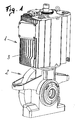
- zeigt eine Motor-Getriebe-Einheit in dreidimensionaler Darstellung;
- Fig. 2
- einen prinzipiellen Aufbau einer Asynchron-Traktionsmaschine als Motor-Getriebe-Einheit im Querschnitt;
- Fig. 3
- ein Motorgehäuse in dreidimensionaler Darstellung;
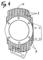
- Fig. 4
- eine Draufsicht auf die senkrecht eingebaute Einheit und
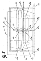
- Fig. 5
- eine Struktur eines Wärmequellennetzwerkes für eine gekapselte, elektrische Maschine als Prinzipschaltbild.
- Fig. 1
- shows a motor-gear unit in three-dimensional representation;
- Fig. 2
- a basic structure of an asynchronous traction engine as a motor-gear unit in cross section;
- Fig. 3
- a motor housing in three-dimensional representation;
- Fig. 4
- a plan view of the vertically installed unit and
- Fig. 5
- a structure of a heat source network for an encapsulated electrical machine as a schematic diagram.
Einführend sei festgehalten, dass in der beschriebenen Ausführungsform gleiche Teile bzw. Zustände mit gleichen Bezugszeichen bzw. gleichen Bauteilbezeichnungen versehen werden, wobei die in der gesamten Beschreibung enthaltenen Offenbarungen sinngemäß auf gleiche Teile bzw. Zustände mit gleichen Bezugszeichen bzw. gleichen Bauteilbezeichnungen übertragen werden können.By way of introduction, it should be noted that in the described embodiment same parts or states with the same reference numerals or the same component designations are provided, which in the entire The disclosures contained in the description corresponding to the same Parts or states with the same reference symbols or the same component designations can be transmitted.
Gemäß der Fig. 1 ist eine gekapselte, elektrische Maschine 1 mit angebautem Getriebe 2 als Motor-Getriebe-Einheit im Querschnitt dargestellt, wobei diese Einheit für den Traktionsbetrieb konstruiert ist. Insbesondere beim Traktionsbetrieb werden derartige Einheiten, beispielsweise bei Straßenbahnen als Einzelradantrieb, eingesetzt. Derartige Einzelradantriebe sind in den Portalen der Drehgestelle vorgesehen. Die Maschine 1 weist keine aktive Belüftung oder zusätzliche Kühlmedien auf.1 is an encapsulated electrical machine 1 with mounted gearbox 2 as a motor-gear unit in cross section shown, which unit designed for traction operation is. In particular, in traction operation such Units, for example trams as a single-wheel drive, used. Such single wheel drives are in the portals of Bogies provided. The machine 1 has no active ventilation or additional cooling media.
Die Abführung der Verlustwärme erfolgt durch natürliche Konvektion bzw. Strahlung und gegebenenfalls durch eine vom Fahrtwind erzeugte Konvektion, wobei das Maschinengehäuse aus Leichtmetall, vorzugsweise Aluminium, hergestellt ist und außen, diagonal gegenüberliegende, überlange Kühlrippen 3 aufweist, auf die später noch näher eingegangen wird. The dissipation of heat loss occurs by natural convection or radiation and optionally by a generated by the wind Convection, wherein the machine housing made of light metal, preferably Aluminum, is made and outside, diagonally opposite, has overlong cooling fins 3, on the later will be discussed in more detail.
Die für die Kühlung notwendige Oberfläche der anzuordnenden Kühlrippen 3 wird über ein, später noch beschriebenes, Rechen- bzw. Datenverarbeitungsprogramm berechnet. Die zur Kühlung errechnete und benötigte Oberfläche kann dann auf die Anzahl und Abmessungen der Kühlrippen 3 übergeführt werden. Die überlangen Kühlrippen 3 können dann konstruktiv so angeordnet werden, dass einerseits die errechnete Oberfläche erreicht wird und anderseits den Einbauverhältnissen Rechnung getragen wird.The necessary for the cooling surface of the arranged cooling fins 3 is about a, later described, computer or data processing program calculated. The calculated for cooling and required surface can then be limited to the number and dimensions of Cooling fins 3 are transferred. The overlong cooling fins 3 can then constructively arranged so that on the one hand the calculated Surface is achieved and on the other hand, the installation conditions Account is taken.
Der Aufbau der Motor-Getriebe-Einheit wird an Hand der Fig. 2 näher erläutert. Die Maschine 1 besteht aus einem Stator 4 und einem, auf einer rotierenden Welle 5 befestigten, Rotor 6. Sowohl der Stator 4, wie auch der Rotor 6 sind aus einzelnen, zu Blechpaketen zusammengefügten, Blechen aufgebaut. Der Stator 4 besteht aus gestanzten Statorblechen, die zum Statorblechpaket geschichtet werden. Weiters ist im Stator 4 die Statorwicklung mit den seitlich herausragenden Wickelköpfen 7 angeordnet. Der Rotor 6 besteht ebenfalls aus gestanzten Rotorblechen die zum Rotorblechpaket geschichtet werden und weist die Rotorwicklung mit den Kurzschlussringen 8 auf.The construction of the motor-gear unit will become more apparent with reference to FIG. 2 explained. The machine 1 consists of a stator 4 and a, on a rotating shaft 5 fixed, rotor 6. Both the stator 4, as well as the rotor 6 are made of individual, assembled into laminated cores, Built up sheets. The stator 4 consists of stamped stator laminations, which laminated to the laminated stator core become. Furthermore, in the stator 4, the stator winding with the side outstanding winding heads 7 are arranged. The rotor 6 is also made from stamped rotor laminations which are laminated to the rotor core be and has the rotor winding with the shorting rings. 8 on.
Antriebsseitig ist die Welle 5 der Maschine 1 derart ausgeführt, dass der Wellenstummel 9 des Getriebes 2 mit der Welle 5 verbunden werden kann. Dies kann über eine form- und/oder kraftschlüssige Verbindung erfolgen. Die antriebsseitige Lagerung der Maschine 1 erfolgt über das Getriebe 2, das an das Maschinengehäuse angeflanscht ist.On the drive side, the shaft 5 of the machine 1 is designed such that that the stub shaft 9 of the transmission 2 is connected to the shaft 5 can be. This can be done via a positive and / or non-positive connection respectively. The drive-side mounting of the machine 1 takes place via the gearbox 2, which flanged to the machine housing is.
Wie weiter oben beschrieben, muss die in der gekapselten Maschine 1 entstehende Verlustwärme über die Oberfläche des Maschinengehäuses abgeführt werden. Dies erfolgt durch natürliche Konvektion bzw. Strahlung und gegebenenfalls durch eine vom Fahrtwind erzeugte Konvektion, was auf Grund der Höhe dieser anfallenden Verlustwärrrie eine große Oberfläche bedingt.As described above, in the encapsulated machine 1 resulting heat loss across the surface of the machine housing be dissipated. This is done by natural convection or Radiation and optionally by a convection generated by the wind, due to the amount of this heat loss a large surface conditionally.
Gemäß der Fig. 3 ist ein aus Aluminium gefertigtes Gehäuse 10 für die Maschine 1 aufgezeigt, mit dem diese auftretenden schwierigen Probleme bewältigt und auch beherrscht werden können. Das Gehäuse 10 weist außen, diagonal gegenüberliegende, überlange Kühlrippen 3 auf. Die überlangen Kühlrippen 3 schaffen, trotz Kapselung der Maschine 1, durch ihre Oberfläche die notwendige Kühlung. Dies ist auf die Verwendung von Aluminium zurückzuführen, da Aluminium eine um den Faktor 10 bessere Wärmeleitfähigkeit als Stahlguss aufweist. Durch diese exzellente Wärmeleitfähigkeit werden die überlangen Kühlrippen 3 wärmetechnisch wirksam.According to FIG. 3, a housing 10 made of aluminum is intended for the machine 1 shown, with which these occurring difficult Problems can be mastered and mastered as well. The housing 10 has outer, diagonally opposite, overlong cooling fins third on. The overlong cooling fins 3 create, despite encapsulation of the machine 1, through its surface the necessary cooling. This is due to the use of aluminum, because aluminum is a has a factor of 10 better thermal conductivity than cast steel. Due to this excellent thermal conductivity, the overlong Cooling fins 3 thermally effective.
Bei eingebauter Maschine 1 sind die Kühlrippen 3 senkrecht angeordnet. Durch diese Art der Konstruktion der Kühlrippen 3 wird eine sehr große Oberfläche für die Wärmeabfuhr durch Konvektion geschaffen. Durch den Verlauf der Kühlrippen 3 parallel zueinander, die mindestens auf einer Seite der Maschine 1 angeordnet sind, wird eine maximale Kühloberfläche bei geringstem Raumbedarf erreicht. Ferner werden - bei Anordnung der Kühlrippen 3 auf beiden Seiten der Maschine 1 - durch die miteinander fluchtende, diagonal gegenüberliegende Anordnung der Kühlrippen 3 die vorgegebenen Einbauverhältnisse in einem Antriebsportal optimal ausgenützt.When installed machine 1, the cooling fins 3 are arranged vertically. By this type of construction of the cooling fins 3 is a very large surface created for the heat dissipation by convection. By the course of the cooling fins 3 parallel to each other, the are arranged at least on one side of the machine 1, is Achieved a maximum cooling surface with minimal space requirements. Further, in the arrangement of the cooling fins 3 on both sides the machine 1 - through the aligned, diagonally opposite Arrangement of the cooling fins 3, the given installation conditions optimally utilized in a drive portal.
Wie bereits oben ausgeführt, sind die Einbauverhältnisse im Antriebsportal meist vorgegeben. Durch die Anordnung und/oder Formgebung der Kühlrippen 3, die praktisch frei konstruiert bzw. gewählt werden kann, kann die Maschine den Einbau- und/oder Platzverhältnissen entsprechend angepasst werden und kann auch diesen Vorgaben Rechnung getragen werden.As already stated above, the installation conditions in the drive portal usually predetermined. By the arrangement and / or shaping the cooling fins 3, which constructed virtually free or elected can be, the machine can the installation and / or space conditions can be adjusted accordingly and can also meet these requirements Be taken into account.
Entsprechend der Fig. 4 - die eine Ansicht von der Seite des Getriebes 2 zeigt -wird eine nochmalige Vergrößerung der für die Konvektion zu Verfügung stehenden Oberfläche aufgezeigt. Dabei sind mindestens ein Teil der Kühlrippen 3, beispielsweise einer Seite der Maschine 1, an ihren freien Enden über einen Mantel 11 verbunden. Der Mantel 11 kann sich nur über einen Teil der Oberfläche der Maschine 1 erstrecken. Im Extremfall kann dieser Mantel 11 auch ein Zylinder sein, der die Maschine 11 quasi umhüllt. Es können aber auch die Kühlrippen 3 im Bereich ihrer freien Enden mit Stege 14 verbunden werden. Ein derartiger Mantel 11 bzw. die Verbindung der Kühlrippenspitzen mit Stege 14 bringt einerseits eine drastische Reduzierung der Lärmabstrahlung und anderseits wird die aktive Kühlungsoberfläche noch weiter erhöht. Ein derartiger Mantel 11 kann an den Spitzen der Kühlrippen 3 mittels einer Schweißverbindung vorgesehen werden. Bei der Anordnung von Stegen 14 können diese im Bereich der Kühlrippenspitzen mit den Kühlrippen 3 verbunden werden.According to Fig. 4 - which is a view from the side of the transmission Figure 2 shows a further increase in convection indicated surface available. There are at least a portion of the cooling fins 3, for example, one side the machine 1, connected at their free ends via a jacket 11. The jacket 11 can only cover part of the surface extend the machine 1. In extreme cases, this jacket 11 also be a cylinder that covers the machine 11 quasi. It can but also the cooling fins 3 in the region of their free ends with webs 14 are connected. Such a jacket 11 or the connection the cooling fin tips with webs 14 brings on the one hand a drastic Reduction of noise emission and on the other hand becomes the active Cooling surface further increased. Such a coat 11 may be at the tips of the cooling fins 3 by means of a welded joint be provided. In the arrangement of webs 14 can these are connected to the cooling ribs 3 in the area of the cooling rib tips become.
Der Wirkungsgrad für die Wärmeabfuhr könnte auch noch dadurch verbessert werden, wenn bei senkrechter, eingebauter Maschine 1 im Bereich knapp über dem oberen Lagerschild bzw. den Kühlrippen, also der dieser Ansicht gegenüberliegenden Seite, Luftleitbleche od. dgl. vorgesehen werden. Durch eine intelligente Anordnung von Leitblechen o. dgl. kann eine Saugströmung über der Maschine 1 erreicht werden, wodurch die Wärmeabfuhr noch erhöht werden kann. Wie später noch detaillierter ausgeführt wird, ist die Auslegung einer Traktionsmaschine vom Fahrspiel abhängig. Durch die Fahrbewegung wird eine Luftströmung in dem Fahrzeug bewirkt, die für die Saugströmung ausgenützt werden kann.The efficiency for heat dissipation could also be improved when in vertical, built-in machine 1 in the area just above the upper bearing plate or the cooling fins, so the opposite side of this view, baffles od. Like. Be provided. Through an intelligent arrangement of baffles o. The like. Can reach a suction flow over the machine 1 be, whereby the heat dissipation can be increased. How later To be more detailed, is the design of a traction machine depending on the driving game. By the driving movement becomes an air flow in the vehicle causes, for the suction flow can be exploited.
Zur Berechnung und Auslegung der elektrischen Maschine 1, die auch die Berechnung der Oberfläche für die Kühlung mit umfasst, ist ein Datenverarbeitungsprogramm vorgesehen, das zur Ermittlung von Zustandsgrößen, insbesondere der Temperaturen und Wärmeströme, vorzugsweise für den stationären Endzustand und/oder für den dynamischen Fahrbetrieb, in der elektrischen Maschine dient. Dieses Datenverarbeitungsprogramm führt die Berechnungen über ein Wärmequellennetzwerk durch.To calculate and design the electric machine 1, which too The calculation includes the surface for cooling with is a Data processing program provided for determining state variables, in particular the temperatures and heat flows, preferably for the stationary end state and / or for the dynamic Driving, serving in the electric machine. This data processing program introduces the calculations Heat source network through.
Gemäß der Fig. 5 ist eine Struktur eines Wärmequellennetzwerkes für eine elektrische Maschine 1 als Prinzipschaltbild dargestellt.Referring to FIG. 5, a structure of a heat source network for an electrical machine 1 shown as a schematic diagram.
Mit einem Datenverarbeitungsprogramm wird entsprechend der geometrischen Definition der Maschine, wie vorzugsweise Abmessungen, Nutenform, Wicklungsart, Materialeigenschaften die Struktur des Wärmequellennetzes 12 erstellt. Weiters werden Knotenpunkte 13 für das Wärmequellennetz 12 festgelegt und zwischen den Knotenpunkten 13 die thermischen Übergangswiderstände definiert. Aus diesen Parametern werden die Temperaturen für den stationären Endzustand errechnet.Using a data processing program will be according to the geometric Definition of the machine, such as preferably dimensions, groove shape, Winding type, material properties the structure of Heat source network 12 created. Furthermore, nodes 13 for set the heat source network 12 and between the nodes 13 defines the thermal contact resistance. From these parameters the temperatures for the stationary final state are calculated.
Es wird mindestens jeweils ein Knotenpunkt für die Zähne im Stator 13a und im Rotor 13b, für die Nuten jeweils im Stator 13c und im Rotor 13d, für den Luftspalt 13e, für das Statorjoch 13f, für das Rotorjoch 13g, für jede Seite des Wickelkopfes 13h, 13i und für den Kurzschlussring auf jeder Seite 13j, 13k festgelegt. Zur genaueren Auslegung der Maschine kann im Statorjoch 13f und den angrenzenden Konstruktionsteilen mindestens ein weiterer Knotenpunkt 131, vorzugsweise für das Gehäuse 10 bzw. die Kühlrippen 3, festgelegt werden. Zum gleichen Zweck kann im Rotorjoch 13g im Bereich der Welle 5 mindestens ein weiterer Knotenpunkt 13m festgelegt werden und der zwischen den Knotenpunkten 13b, 13m auftretende Übergangswiderstand wird in die Berechnung einbezogen.There will be at least one node each for the teeth in the stator 13a and 13b in the rotor, for the grooves in the stator 13c and in the Rotor 13d, for the air gap 13e, for the stator yoke 13f, for the Rotor yoke 13g, for each side of the winding head 13h, 13i and for the Short circuit ring set on each side 13j, 13k. For the more precise Design of the machine can be in Statorjoch 13f and the adjacent Constructing at least one further node 131, Preferably, for the housing 10 and the cooling fins 3, set become. For the same purpose can in the rotor yoke 13g in the field of Wave 5 at least one further node 13m are set and the contact resistance occurring between the nodes 13b, 13m will be included in the calculation.
Weiters können auch für die Innenluft der Maschine 1, nahe den Lagern, zusätzliche Knotenpunkte 13n, 13o bzw. einer für die Umgebungsluft festgelegt werden.Furthermore, also for the inside air of the machine 1, near the Store, additional nodes 13n, 13o or one for the ambient air be determined.
Da die Welle 5 der Maschine 1 sicher ein neuralgischer Maschinenteil ist, werden auch für das getriebeseitige Wellenende und das korrespondierende Wellenende, auf dem eine Bremsscheibe angeordnet sein kann, Knotenpunkte 13r, 13s festgelegt. Natürlich können noch weitere Knotenpunkte 13 für eine höhere Exaktheit der Berechnung festgelegt werden.Since the shaft 5 of the machine 1 certainly a neuralgischer machine part is also for the transmission side shaft end and the corresponding shaft end on which a brake disc arranged may be nodes 13r, 13s set. Of course you can still further nodes 13 for a higher accuracy of the calculation be determined.
Weiters kann in der Berechnung der Verluste für die einzelnen Knotenpunkte 13 und/oder der thermischen Übergangswiderstände zwischen den einzelnen Knotenpunkten 13 das dynamische Verhalten der Maschine im Betrieb, insbesondere das Fahrspiel, berücksichtigt werden. Wie bereits erwähnt, ein weiterer Schritt sich den tatsächlichen Grenzwerten der Maschine zu nähern.Furthermore, in calculating the losses for the individual Junctions 13 and / or the thermal contact resistance between the individual nodes 13, the dynamic behavior of Machine in operation, especially the driving game, considered become. As already mentioned, another step up the actual Limit values of the machine.
Die thermischen Übergangswiderstände werden unter Berücksichtigung des dynamischen Verhaltens der Maschine im Betrieb, insbesondere der Drehzahl und/oder der Geschwindigkeit des Fahrzeuges während des Fahrspiels, berechnet. Daraus ergibt sich, - ebenfalls erwähnt - dass die Maschine nicht auf die Temperaturen des stationären Endzustandes berechnet wird, sondern auf die tatsächlichen Werte im Betrieb.The thermal contact resistances are taken into account the dynamic behavior of the machine in operation, in particular the speed and / or speed of the vehicle during of the driving game, calculated. It follows, - also mentioned - that the machine does not respond to the temperatures of the stationary final state is calculated, but on the actual values in the Business.
Das Netzwerk der thermischen Übergangswiderstände wird durch die thermischen Kapazitäten der den Knoten entsprechenden Regionen der Maschine ergänzt.The network of thermal contact resistance is through the thermal capacities of the regions corresponding to the nodes the machine complements.
Ferner kann in der Berechnung der Verluste für die einzelnen Knotenpunkte 13 und/oder der thermischen Übergangswiderstände zwischen den einzelnen Knotenpunkten 13 die Temperaturabhängigkeit der Materialien mittels eines Temperaturfaktors berücksichtigt werden.Furthermore, in the calculation of losses for each Junctions 13 and / or the thermal contact resistance between the individual nodes 13, the temperature dependence of the materials by means of a temperature factor become.
Das dynamische Verhalten der Maschine im Betrieb, insbesondere während des Fahrspiels, wird in der Berechnung dynamisch simuliert und daraus werden Mittelwerte gerechnet.The dynamic behavior of the machine in operation, in particular during the driving game, is dynamically simulated in the calculation and from this average values are calculated.
Ebenso werden bei der Berechnung der thermischen Übergangswiderstände Korrekturfaktoren eingeführt, die vorzugsweise aus Erfahrungswerten gebildet werden.Likewise, when calculating the thermal contact resistance Correction factors are introduced, which are preferably made Experience values are formed.
An Hand eines Beispieles wird das Verfahren zur Auslegung einer Maschine näher erläutert:By way of example, the method for designing a Machine explained in more detail:
Die Formeln für thermische Widerstände haben immer denselben
Aufbau. Im Falle der Wärmeleitung lautet der thermische
Widerstand
- Rth
- thermischer Widerstand
- λ
- spezifische Wärmeleitfähigkeit [W/m.K]
- AQ
- Querschnitt, der für die Wärmeleitung zur Verfügung steht
- l
- Länge, über die Wärme transportiert wird.
- R th
- thermal resistance
- λ
- specific thermal conductivity [W / mK]
- AQ
- Cross-section available for heat conduction
- l
- Length over which heat is transported.
Am Beispiel des thermischen Widerstandes Rth zwischen Stator-Nut und dem Stator-Zahn sei die Anwendung dieser Formel demonstriert.Using the example of the thermal resistance R th between the stator slot and the stator tooth, the application of this formula is demonstrated.
Es handelt sich um eine Serienschaltung aus einer Strecke im
Wickelkupfer Rth,cu einer Strecke durch Isolation Rth,Is und einer
Strecke durch Eisen (Dynamoblech) Rth,Fe:
Der thermische Widerstand im Wickelkupfer beträgt
- bCu
- Breite des Wickelkupfers in der Nut
- λCu
- Wärmeleitfähigkeit von Kupfer
- N1
- Statornutenzahl (Es werden alle Nuten in einem thermischen Knoten zusammengefasst.)
- hCu
- maßgebliche Höhe des Wickelkupfers in der Nut
- lFe
- Länge des Blechpaketes
- kKorr
- Korrekturfaktor, der unter anderem berücksichtigt, dass die Verlustwärme im Wickelkupfer verteilt entsteht.
- b Cu
- Width of the winding copper in the groove
- λ Cu
- Thermal conductivity of copper
- N 1
- Stator Slot Number (All slots are grouped together in one thermal node.)
- h Cu
- decisive height of the winding copper in the groove
- l Fe
- Length of the laminated core
- k corr
- Correction factor that takes into account, among other things, that the heat loss in the winding copper is distributed.
Der thermische Widerstand der Isolation beträgt
- bIs
- einseitige Dicke der Isolation
- λIs
- Wärmeleitfähigkeit des Isolationsmaterials
- kKorr
- Korrekturfaktor
- b Is
- one-sided thickness of the insulation
- λ Is
- Thermal conductivity of the insulation material
- k corr
- correction factor
Der thermische Widerstand der Strecke im Eisen beträgt
schließlich
- bZahn
- Zahnbreite
- λFe
- Wärmeleitfähigkeit von Eisen (Dynamoblech)
- hNut
- maßgebliche Nuthöhe
- kKorr
- Korrekturfaktor, der unter anderem die Schichtung aus einseitig lackierten Dynamoblechen berücksichtigt.
- b tooth
- tooth width
- λ Fe
- Thermal conductivity of iron (dynamo plate)
- h groove
- significant groove height
- k corr
- Correction factor that takes into account, among other things, the stratification of single-side coated dynamo sheets.
Im Falle eines Wärmeüberganges Λ auf ein Kühlmedium lautet die
Formel
- α
- Wärmeübergangszahl [W/m2.K]
- AÜ
- Fläche, die für den Wärmeübergang zur Verfügung steht.
- α
- Heat transfer coefficient [W / m 2 .K]
- A Ü
- Area available for heat transfer.
Die Wärmeübergangszahl α ist stark von den Strömungsverhältnissen und der Oberflächengeometrie, wie eben den überlangen Kühlrippen, abhängig.The heat transfer coefficient α is strong on the flow conditions and the surface geometry, as well as the overlong Cooling fins, depending.
Für die Auslegung der Maschine werden zur Berücksichtigung des dynamischen Verhaltens der Maschine zu den thermischen realen Widerständen auch thermische Kapazitäten hinzugefügt, über welche die zeitliche Abhängigkeit der Temperaturverteilung in der Maschine berücksichtigt werden kann. Durch das Hinzufügen der Kapazitäten werden komplexe thermische Widerstände geschaffen, in denen auch die thermische Zeitkonstante verankert ist. Die thermischen Kapazitäten werden aufgrund der Geometriematerialien und Randbedingungen der elektrischen Maschine festgelegt.For the design of the machine are to take into account the dynamic behavior of the machine to the thermal real Resistors also added thermal capacity over which the temporal dependence of the temperature distribution in the Machine can be considered. By adding the Capacities are created complex thermal resistances in which the thermal time constant is anchored. The Thermal capacities are due to the geometry materials and boundary conditions of the electrical machine.
Anhand eines fiktiven oder realen Fahrspieles werden Werte, wie Drehzahl der Maschine, Geschwindigkeit oder Beschleunigung des angetriebenen Fahrzeugs und Verluste in Abhängigkeit der Zeit ermittelt. Zu den Verlusten zählen die Eisenverluste, Kupferverluste im Stator und Rotor sowie mechanische Verluste und sogenannte Zusatzverluste, welche alle anderen nicht zuordenbare Verluste beinhalten. Die Parameter in Abhängigkeit der Zeit entsprechend dem Fahrspiel werden zur thermischen Berechnung der Maschine herangezogen. Anhand des Wärmequellennetzes werden Differenzialgleichungen aufgestellt und durch deren Lösung die Temperaturen oder Wärmeströme in den Knoten des Wärmequellennetzes, welche bestimmte Stellen an der Maschine entsprechen, in Abhängigkeit der Zeit berechnet. Durch Aneinanderreihen mehrerer Fahrspiele nähert sich die ermittelte Temperatur einem bestimmten Grenzwert, im sogenannten Zustand der Beharrung. Diese Grenzwerte werden für die Auslegung der Maschine herangezogen. Durch die Berücksichtigung der dynamischen Verhältnisse kommt man sehr nahe an die realen Bedingungen heran, wodurch die elektrische Maschine optimal ausgelegt werden kann.On the basis of a fictional or real driving game values, such as Speed of the machine, speed or acceleration of the machine driven vehicle and losses as a function of time determined. Losses include iron losses, copper losses in the stator and rotor as well as mechanical losses and so-called Additional losses, which all other unassignable Losses include. The parameters according to the time accordingly the driving game are used for the thermal calculation of Machine used. Based on the heat source network differential equations set up and by solving the temperatures or heat flows in the nodes of the heat source network, which correspond to specific locations on the machine, depending on the time is calculated. By juxtaposing several Driving games approach the determined temperature a certain Limit, in the so-called state of inertia. These Limit values are used for the design of the machine. By considering the dynamic conditions comes you get very close to the real conditions, which makes the electrical machine can be optimally designed.
Abschließend sei der Ordnung halber darauf hingewiesen, dass in der Zeichnung einzelne Bauteile und Baugruppen zum besseren Verständnis der Erfindung unproportional und maßstäblich verzerrt dargestellt sind.Finally, for the sake of order, it should be noted that in the drawing of individual components and assemblies for better understanding disproportionately and scaled to scale are shown.
Claims (16)
Applications Claiming Priority (2)
| Application Number | Priority Date | Filing Date | Title |
|---|---|---|---|
| AT15762003 | 2003-10-06 | ||
| AT15762003A AT504056B1 (en) | 2003-10-06 | 2003-10-06 | CAPSULATED, ELECTRIC MACHINE |
Publications (2)
| Publication Number | Publication Date |
|---|---|
| EP1523085A2 true EP1523085A2 (en) | 2005-04-13 |
| EP1523085A3 EP1523085A3 (en) | 2005-10-05 |
Family
ID=34280368
Family Applications (1)
| Application Number | Title | Priority Date | Filing Date |
|---|---|---|---|
| EP04450187A Withdrawn EP1523085A3 (en) | 2003-10-06 | 2004-10-06 | Enclosed electrical machine and method to design such a machine |
Country Status (3)
| Country | Link |
|---|---|
| EP (1) | EP1523085A3 (en) |
| AT (1) | AT504056B1 (en) |
| DE (1) | DE202004021506U1 (en) |
Cited By (3)
| Publication number | Priority date | Publication date | Assignee | Title |
|---|---|---|---|---|
| DE202008006366U1 (en) | 2007-05-14 | 2008-07-17 | Traktionssysteme Austria Gmbh | Housing for electrical machines and damping element for it |
| CN104885339A (en) * | 2012-12-21 | 2015-09-02 | 万高电机设备公司 | Heat exchange system for casings of rotary electric machines |
| WO2017194522A1 (en) * | 2016-05-10 | 2017-11-16 | Abb Schweiz Ag | A stator frame of an electrical machine and an electrical machine |
Families Citing this family (1)
| Publication number | Priority date | Publication date | Assignee | Title |
|---|---|---|---|---|
| DE102010025352B4 (en) | 2010-06-28 | 2019-12-24 | Audi Ag | Method for manufacturing an electric machine of a motor vehicle |
Citations (4)
| Publication number | Priority date | Publication date | Assignee | Title |
|---|---|---|---|---|
| GB1248957A (en) * | 1968-12-16 | 1971-10-06 | Gen Electric Co Ltd | Improvements in or relating to electric motors |
| EP0190602A1 (en) * | 1985-02-04 | 1986-08-13 | Siemens Aktiengesellschaft | Stator easing for a surface cooled electrical machine |
| US5789833A (en) * | 1995-11-24 | 1998-08-04 | Kabushiki Kaisha Toshiba | Totally-enclosed traction motor for electric railcar |
| US5877576A (en) * | 1992-02-11 | 1999-03-02 | General Electric Company | Stator frame for dynamoelectric machine and method for making same |
Family Cites Families (8)
| Publication number | Priority date | Publication date | Assignee | Title |
|---|---|---|---|---|
| GB766951A (en) * | 1954-02-06 | 1957-01-30 | Siemens Ag | Improvements in or relating to electric mining machines |
| DE3501185A1 (en) * | 1985-01-16 | 1986-07-17 | Robert Bosch Gmbh, 7000 Stuttgart | Generator set |
| JPH06311691A (en) * | 1993-04-15 | 1994-11-04 | Meidensha Corp | Motor for electric car |
| EP0712545B1 (en) * | 1994-06-08 | 2002-08-14 | Precise Power Corporation | Versatile ac dynamo-electric machine |
| DE19711117C1 (en) * | 1997-03-05 | 1998-09-03 | Mannesmann Ag | System for compressing a gaseous medium or for creating a vacuum |
| DE19716758C2 (en) | 1997-04-12 | 2002-01-10 | System Antriebstechnik Dresden | Housing-free electrical machine with several axial cooling channels with direct fluid flow |
| DE19808602C1 (en) * | 1998-02-28 | 1999-09-02 | Grundfos As | Device for external cooling of the electric drive motor of a centrifugal pump unit |
| EP1087273A1 (en) * | 1999-09-21 | 2001-03-28 | Va Tech Elin GmbH | Method and workstation for simulating an industrial installation |
-
2003
- 2003-10-06 AT AT15762003A patent/AT504056B1/en not_active IP Right Cessation
-
2004
- 2004-10-06 EP EP04450187A patent/EP1523085A3/en not_active Withdrawn
- 2004-10-06 DE DE200420021506 patent/DE202004021506U1/en not_active Expired - Lifetime
Patent Citations (4)
| Publication number | Priority date | Publication date | Assignee | Title |
|---|---|---|---|---|
| GB1248957A (en) * | 1968-12-16 | 1971-10-06 | Gen Electric Co Ltd | Improvements in or relating to electric motors |
| EP0190602A1 (en) * | 1985-02-04 | 1986-08-13 | Siemens Aktiengesellschaft | Stator easing for a surface cooled electrical machine |
| US5877576A (en) * | 1992-02-11 | 1999-03-02 | General Electric Company | Stator frame for dynamoelectric machine and method for making same |
| US5789833A (en) * | 1995-11-24 | 1998-08-04 | Kabushiki Kaisha Toshiba | Totally-enclosed traction motor for electric railcar |
Non-Patent Citations (3)
| Title |
|---|
| RAKOTONIRINA G ET AL: "A new approach to modeling core losses in squirrel cage induction motor using polynomial functions" ELECTRICAL AND COMPUTER ENGINEERING, 2001. CANADIAN CONFERENCE ON MAY 13-16, 2001, PISCATAWAY, NJ, USA,IEEE, Bd. 1, 13. Mai 2001 (2001-05-13), Seiten 551-556, XP010550892 ISBN: 0-7803-6715-4 * |
| ROY D ET AL: "Novel thermal model aided motor derating under waveform distortion" POWER ELECTRONICS AND DRIVE SYSTEMS, 1997. PROCEEDINGS., 1997 INTERNATIONAL CONFERENCE ON SINGAPORE 26-29 MAY 1997, NEW YORK, NY, USA,IEEE, US, Bd. 2, 26. Mai 1997 (1997-05-26), Seiten 829-833, XP010244606 ISBN: 0-7803-3773-5 * |
| STATON D ET AL: "Solving the more difficult aspects of electric motor thermal analysis" ELECTRIC MACHINES AND DRIVES CONFERENCE, 2003. IEMDC'03. IEEE INTERNATIONAL JUNE 1-4, 2003, PISCATAWAY, NJ, USA,IEEE, Bd. 2, 1. Juni 2003 (2003-06-01), Seiten 747-755, XP010643436 ISBN: 0-7803-7817-2 * |
Cited By (6)
| Publication number | Priority date | Publication date | Assignee | Title |
|---|---|---|---|---|
| DE202008006366U1 (en) | 2007-05-14 | 2008-07-17 | Traktionssysteme Austria Gmbh | Housing for electrical machines and damping element for it |
| CN104885339A (en) * | 2012-12-21 | 2015-09-02 | 万高电机设备公司 | Heat exchange system for casings of rotary electric machines |
| CN104885339B (en) * | 2012-12-21 | 2018-05-04 | 万高电机设备公司 | The heat-exchange system of electric rotating machine housing |
| WO2017194522A1 (en) * | 2016-05-10 | 2017-11-16 | Abb Schweiz Ag | A stator frame of an electrical machine and an electrical machine |
| KR20190002619A (en) * | 2016-05-10 | 2019-01-08 | 에이비비 슈바이쯔 아게 | Stator frames and electric machines of electric machines |
| US10530214B2 (en) | 2016-05-10 | 2020-01-07 | Abb Schweiz Ag | Stator frame of an electrical machine and an electrical machine |
Also Published As
| Publication number | Publication date |
|---|---|
| EP1523085A3 (en) | 2005-10-05 |
| AT504056A1 (en) | 2008-02-15 |
| DE202004021506U1 (en) | 2008-07-17 |
| AT504056B1 (en) | 2009-08-15 |
Similar Documents
| Publication | Publication Date | Title |
|---|---|---|
| DE19648455C2 (en) | Encapsulated traction motor for an electric rail vehicle | |
| DE69503521T3 (en) | SYNCHRONOUS MOTOR WITH PERMANENT MAGNETS | |
| DE102011056183A1 (en) | Drive device of a magnetic levitation railway | |
| DE102019106801A1 (en) | Electric machine with cooling | |
| WO2019110275A1 (en) | Electrical machine, in particular for a vehicle | |
| WO2019141518A1 (en) | Bogie of a rail vehicle | |
| WO2012085280A2 (en) | Electrical machine comprising a can and method for producing same | |
| AT522711A1 (en) | Stator for an axial flux machine | |
| DE102019112389A1 (en) | Cooling of electric motors | |
| EP2989711A1 (en) | Air-cooled electric machine having cooling ribs formed from stator sheet | |
| DE4111627C2 (en) | Electric motor for an electric vehicle for installation in a wheel rim | |
| DE102021202146A1 (en) | ELECTRIC MOTOR COOLING SYSTEM AND METHOD OF OPERATING THE SYSTEM | |
| DE19743906A1 (en) | Wheel drive device | |
| EP1515417A2 (en) | Closed elecrtrical machine and method to design such a machine | |
| DE4234145C1 (en) | Multi-phase electrical machines with prefabricated conductor strands and processes for their manufacture | |
| DE102011012453A1 (en) | Electric machine e.g. generator of wind turbine, has stator that is composed of inner and outer stators to which cooling water is supplied through cylindrical pipes | |
| EP1523085A2 (en) | Enclosed electrical machine and method to design such a machine | |
| DE19753261A1 (en) | AC machine esp transverse flux type | |
| DE19753320A1 (en) | AC machine esp transverse flux type | |
| EP4158764B1 (en) | Electric traction machine with no housing | |
| DE102021133029A1 (en) | stator | |
| DE102014213276A1 (en) | Linear drive with high power density | |
| DE102021108949A1 (en) | electrical machine | |
| DE102021108951A1 (en) | electrical machine | |
| EP3857684B1 (en) | Housingless electric traction machine |
Legal Events
| Date | Code | Title | Description |
|---|---|---|---|
| PUAI | Public reference made under article 153(3) epc to a published international application that has entered the european phase |
Free format text: ORIGINAL CODE: 0009012 |
|
| AK | Designated contracting states |
Kind code of ref document: A2 Designated state(s): AT BE BG CH CY CZ DE DK EE ES FI FR GB GR HU IE IT LI LU MC NL PL PT RO SE SI SK TR |
|
| AX | Request for extension of the european patent |
Extension state: AL HR LT LV MK |
|
| PUAL | Search report despatched |
Free format text: ORIGINAL CODE: 0009013 |
|
| AK | Designated contracting states |
Kind code of ref document: A3 Designated state(s): AT BE BG CH CY CZ DE DK EE ES FI FR GB GR HU IE IT LI LU MC NL PL PT RO SE SI SK TR |
|
| AX | Request for extension of the european patent |
Extension state: AL HR LT LV MK |
|
| 17P | Request for examination filed |
Effective date: 20060323 |
|
| AKX | Designation fees paid |
Designated state(s): AT BE BG CH CY CZ DE DK EE ES FI FR GB GR HU IE IT LI LU MC NL PL PT RO SE SI SK TR |
|
| AXX | Extension fees paid |
Extension state: MK Payment date: 20060323 Extension state: LV Payment date: 20060323 Extension state: LT Payment date: 20060323 Extension state: HR Payment date: 20060323 |
|
| 17Q | First examination report despatched |
Effective date: 20080124 |
|
| STAA | Information on the status of an ep patent application or granted ep patent |
Free format text: STATUS: THE APPLICATION HAS BEEN WITHDRAWN |
|
| 18W | Application withdrawn |
Effective date: 20080516 |