EP1522716A2 - Air intake structure of internal combustion engine - Google Patents
Air intake structure of internal combustion engine Download PDFInfo
- Publication number
- EP1522716A2 EP1522716A2 EP04023975A EP04023975A EP1522716A2 EP 1522716 A2 EP1522716 A2 EP 1522716A2 EP 04023975 A EP04023975 A EP 04023975A EP 04023975 A EP04023975 A EP 04023975A EP 1522716 A2 EP1522716 A2 EP 1522716A2
- Authority
- EP
- European Patent Office
- Prior art keywords
- intake air
- intake
- branch pipe
- cylinders
- collector
- Prior art date
- Legal status (The legal status is an assumption and is not a legal conclusion. Google has not performed a legal analysis and makes no representation as to the accuracy of the status listed.)
- Granted
Links
Images


Classifications
-
- F—MECHANICAL ENGINEERING; LIGHTING; HEATING; WEAPONS; BLASTING
- F02—COMBUSTION ENGINES; HOT-GAS OR COMBUSTION-PRODUCT ENGINE PLANTS
- F02M—SUPPLYING COMBUSTION ENGINES IN GENERAL WITH COMBUSTIBLE MIXTURES OR CONSTITUENTS THEREOF
- F02M35/00—Combustion-air cleaners, air intakes, intake silencers, or induction systems specially adapted for, or arranged on, internal-combustion engines
- F02M35/10—Air intakes; Induction systems
- F02M35/104—Intake manifolds
- F02M35/112—Intake manifolds for engines with cylinders all in one line
-
- F—MECHANICAL ENGINEERING; LIGHTING; HEATING; WEAPONS; BLASTING
- F02—COMBUSTION ENGINES; HOT-GAS OR COMBUSTION-PRODUCT ENGINE PLANTS
- F02B—INTERNAL-COMBUSTION PISTON ENGINES; COMBUSTION ENGINES IN GENERAL
- F02B27/00—Use of kinetic or wave energy of charge in induction systems, or of combustion residues in exhaust systems, for improving quantity of charge or for increasing removal of combustion residues
- F02B27/005—Oscillating pipes with charging achieved by arrangement, dimensions or shapes of intakes pipes or chambers; Ram air pipes
-
- F—MECHANICAL ENGINEERING; LIGHTING; HEATING; WEAPONS; BLASTING
- F02—COMBUSTION ENGINES; HOT-GAS OR COMBUSTION-PRODUCT ENGINE PLANTS
- F02M—SUPPLYING COMBUSTION ENGINES IN GENERAL WITH COMBUSTIBLE MIXTURES OR CONSTITUENTS THEREOF
- F02M35/00—Combustion-air cleaners, air intakes, intake silencers, or induction systems specially adapted for, or arranged on, internal-combustion engines
- F02M35/10—Air intakes; Induction systems
- F02M35/10006—Air intakes; Induction systems characterised by the position of elements of the air intake system in direction of the air intake flow, i.e. between ambient air inlet and supply to the combustion chamber
- F02M35/10026—Plenum chambers
- F02M35/10052—Plenum chambers special shapes or arrangements of plenum chambers; Constructional details
-
- F—MECHANICAL ENGINEERING; LIGHTING; HEATING; WEAPONS; BLASTING
- F02—COMBUSTION ENGINES; HOT-GAS OR COMBUSTION-PRODUCT ENGINE PLANTS
- F02M—SUPPLYING COMBUSTION ENGINES IN GENERAL WITH COMBUSTIBLE MIXTURES OR CONSTITUENTS THEREOF
- F02M35/00—Combustion-air cleaners, air intakes, intake silencers, or induction systems specially adapted for, or arranged on, internal-combustion engines
- F02M35/10—Air intakes; Induction systems
- F02M35/10006—Air intakes; Induction systems characterised by the position of elements of the air intake system in direction of the air intake flow, i.e. between ambient air inlet and supply to the combustion chamber
- F02M35/10072—Intake runners
-
- F—MECHANICAL ENGINEERING; LIGHTING; HEATING; WEAPONS; BLASTING
- F02—COMBUSTION ENGINES; HOT-GAS OR COMBUSTION-PRODUCT ENGINE PLANTS
- F02M—SUPPLYING COMBUSTION ENGINES IN GENERAL WITH COMBUSTIBLE MIXTURES OR CONSTITUENTS THEREOF
- F02M35/00—Combustion-air cleaners, air intakes, intake silencers, or induction systems specially adapted for, or arranged on, internal-combustion engines
- F02M35/10—Air intakes; Induction systems
- F02M35/10091—Air intakes; Induction systems characterised by details of intake ducts: shapes; connections; arrangements
- F02M35/10111—Substantially V-, C- or U-shaped ducts in direction of the flow path
-
- Y—GENERAL TAGGING OF NEW TECHNOLOGICAL DEVELOPMENTS; GENERAL TAGGING OF CROSS-SECTIONAL TECHNOLOGIES SPANNING OVER SEVERAL SECTIONS OF THE IPC; TECHNICAL SUBJECTS COVERED BY FORMER USPC CROSS-REFERENCE ART COLLECTIONS [XRACs] AND DIGESTS
- Y02—TECHNOLOGIES OR APPLICATIONS FOR MITIGATION OR ADAPTATION AGAINST CLIMATE CHANGE
- Y02T—CLIMATE CHANGE MITIGATION TECHNOLOGIES RELATED TO TRANSPORTATION
- Y02T10/00—Road transport of goods or passengers
- Y02T10/10—Internal combustion engine [ICE] based vehicles
- Y02T10/12—Improving ICE efficiencies
Definitions
- This invention relates to improvements in an air intake structure of an internal combustion engine.
- Japanese Patent Provisional Publication No. 8-105359 discloses a technique in which a surge tank is disposed one-sided to upstream side air induction pipe placed in one end side in a cylinder row direction of an engine body, and the upstream ends of respective branch pipes of an intake manifold are located closer to the engine body as they come to the downstream side from the upstream side in intake air flow within the surge tank.
- Another object of the present invention is to provide an improved air intake structure of an internal combustion engine, by which intake the waveforms of intake air noises generated under air suctions of respective cylinders of the engine are made uniform while the tone of intake air noise from each cylinder can be made clear.
- an air intake structure of an internal combustion engine comprises an intake air collector having first and second end sides which are longitudinally opposite to each other.
- An intake air inducting pipe is connected to the intake air collector.
- a plurality of branch pipes are connected to the intake air collector and communicated respectively with intake air entrances of cylinders of the engine.
- Each branch pipe is connected through a junction section of the branch pipe to the intake air collector.
- the junction sections of the branch pipes are arranged or aligned along a longitudinal direction of the intake air collector. In this arrangement, the intake air inducting pipe having an opening section serving as the junction section.
- the opening section is located between a first branch pipe located at the first end side of the intake air collector and a second branch pipe located adjacent to the first branch pipe in a longitudinal direction of the intake air collector, and having an axis which is directed to a third branch pipe located at the second end side of the intake air collector.
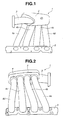
- intake manifold 1 is an inline four-cylinder engine.
- Intake manifold 1 is made of plastic or the like.
- intake manifold 1 includes intake air collector 2 which is elongate and extends along a row of cylinders of engine main body 8.
- Intake air inducting pipe 3 is connected with intake air collector 2.
- Four branch pipes 4a, 4b, 4c and 4d are connected with intake air collector 2.
- intake air is supplied to each cylinder of the engine main body. More specifically, first, second, third, and fourth cylinders C1, C2, C3, C4 are supplied with intake air through branch pipes 4a, 4b, 4c and 4d, respectively.
- intake air is inducted into intake air collector 2.
- Intake air inducting pipe 3 is connected with intake air collector 2 at a side surface opposite to a side surface at which branch pipes 4a to 4d are connected, and on one end side (or left side in Fig. 1) of intake air collector 2 in a longitudinal direction of the intake air collector.
- each branch pipe 4a to 4d Through each branch pipe 4a to 4d, intake air within intake air collector 2 is inducted to an intake air entrance (not shown) of the corresponding cylinder C1, C2, C3, C4.
- One end section of each branch pipe extends generally in the same direction to be connected with intake air collector 2.
- the side surface F at which each branch pipe 4a to 4d is connected as shown in Fig. 2 and Fig. 3 is formed extending generally along a vertical direction of engine main body 8 (i.e., generally along a vertical direction in Fig. 3).
- Each branch pipe 4a t-o 4d is formed to be generally U-shaped as a whole and extends from the intake air entrance opened on the side surface of engine main body 8 toward an upper side of engine main body 8. Therefore, intake air collector 2 is located above engine main body 8.
- the other end section of each branch pipe 4a to 4d is connected with each other by flange 5.
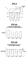
- intake air inducting pipe 3 has intake air inducting pipe opening section 6 at which intake air inducting pipe 3 and intake air collector 2 is connected each other.
- Intake air inducting pipe opening section 6 extends along the longitudinal direction of intake air collector 2.
- Intake air inducting pipe opening section 6 is also located between or bridges branch pipe 4a which is located on one end side of intake air collector 2 and branch pipe 4b which is located adjacent to branch pipe 4a, on a plane of Figs. 1 and 2.
- intake air inducting pipe opening section 6 is formed to be located between or bridge branch pipe opening 7a which is a junction (section) connecting branch pipe 4a with intake air collector 2 and branch pipe opening 7b which is the junction connecting branch pipe 4b with intake air collector 2, in the longitudinal direction of intake air collector 2.
- Fig. 5 is a schematic plan view showing a locational configuration including intake air inducting pipe 3, intake air collector 2 and each branch pipe 4a to 4d.
- intake air inducting pipe opening section 6 has an axis (not shown) which is directed to branch pipe 4d which is nearly located on the other end side (or right side in Fig. 1) of intake air collector 2. More specifically, the axis of intake air inducting pipe opening section 6 is inclined to an axis (not shown) of branch pipe 4 as indicated by an arrow in Fig. 5, on a plane of Fig. 5. The axis of intake air inducting pipe opening section 6 is also formed to be directed to branch pipe opening section 7d which is a junction (section) connecting branch pipe 4d with intake air collector 2. Additionally, 7c denotes a branch pipe opening section which is a junction (section) connecting branch pipe 4c with intake air collector 2.
- intake air passage means a passage through which intake air flows, formed in the air intake structure.
- intake air inducting pipe 3 is connected with intake air collector 2 at a location between branch pipe 4a and branch pipe 4b in the longitudinal direction of intake air collector 2, so that it is possible to decrease a difference in substantial length of the intake air passage among respective cylinders.
- the axis of intake air inducting pipe opening section 6 is directed to branch pipe 4d located the farthest from intake air inducting pipe opening section 6 in the longitudinal direction of intake air collector 2. Therefore, a bend of the intake air inducted from intake air inducting pipe opening section 6 to the branch pipe is increased as,the branch pipe comes close to intake air inducting pipe opening section 6 in the longitudinal direction of intake air collector 2. A pressure loss (or bend loss) generated by the bend of intake air is relatively increased as branch pipe 4 comes close to intake air inducting pipe opening section 6.
- the length from the junction between the branch pipe and intake air collector 2 to intake air inducting pipe opening section 6 become longer as the junction between branch pipe 4 and intake air collector 2 becomes far from intake air inducting pipe opening section 6. Accordingly, a pressure loss (or length loss) generated by the length of the intake air is relatively increased as the branch pipe is far from intake air inducting pipe opening section 6.
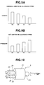
- Fig. 7 differences in the substantial lengths of the intake air passages for the respective cylinders are decreased so that the intake air noise (or sound pressure) generated by differences in the lengths of the intake air passages for the respective cylinders can be effectively decreased as shown in Fig. 7.
- the sound pressure increases as an engine speed of an engine rises, so that a driver does not receive uncomfortable feeling.
- a solid line indicates measurement result of the intake air noise of the intake manifold of this embodiment
- a dotted line indicates measurement result of another intake manifold A which is a comparative example as shown in Fig. 8 which will be discussed after.
- intake manifold A is different from above-described intake manifold 1 of this embodiment only in location at which the connecting section of intake air inducting pipe 13 is connected to intake air collector 11.
- intake manifold A has a common or usual configuration in which intake air inducting pipe 13 is connected to one end section of intake air collector 11, and each branch pipe 10a to 10d is connected to one side surface of intake air collector 11. Therefore, in this intake manifold A, the substantial lengths of the intake air passages for respective cylinders are not equal, and the peak values of pressure waves generated by the cylinders are not equal to each other as shown in Figs. 9A and 9B. Furthermore, in intake manifold A, sound pressure varies with the engine speed as apparent from Fig. 7 so that the driver may receive uncomfortable feeling.
- intake manifold B as shown in Fig. 10 in which each branch pipe 20 is three-dimensionally independent, generally the same substantial length or distance from the opening section of the branch pipe 20 to the opening section of intake air inducting pipe 23 is obtained for the respective branch pipes 20. Therefore, it is possible to make the substantial lengths of the intake air passages for the respective cylinders generally equal as shown in Fig. 11A. Furthermore, it is possible to make pressure wave generated from each cylinder uniform as shown in Fig. 11B.
- a configuration becomes complicated, thereby raising problems such as limitation in manufacturing method (molding is impossible), lowering in productivity, increase in a production cost and increase in weight.
- intake manifold B constructed of intake air inducting pipe 23, intake air collector 21 and each branch pipe 20 becomes larger in size there by causing deterioration in mount ability to a vehicle or the like.
- intake manifold 1 In contrast to intake manifold B, according to the present invention, it is possible to arrange all branch pipes 4a to 4d in a row along the longitudinal direction of intake air collector 2, so that, it is possible to manufacture intake manifold 1 by using a manufacturing method that is the same as that for intake manifold A as shown in Fig. 8 and different to that for intake manifold B as shown in Fig. 10, i.e., by using molding. Therefore, productivity of the intake manifold is not sacrificed.
- intake air inducting pipe 33 is connected to intake air collector 31 near the center of the longitudinal direction of intake air collector 31.
- Each branch pipe 30 is connected to a surface that is opposite to a surface at which intake air inducting pipe 33 is connected.
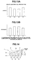
- a width (dimension in vertical direction in Fig. 12) of intake manifold C including intake air inducting pipe 33, intake air collector 31 and branch pipes 30 becomes relatively large, thereby causing degradation of the mount ability to the vehicle or the like.
- the peak values of pressure waves generated by the cylinders are classified into two values as shown in Fig. 13B, so that the tone of intake air noise dulls. Therefore, it is impossible to make the intake air noise clear as same as noise generated by intake manifold 1 of this embodiment.
- intake air structure of this invention is not limited to the above-discussed embodiment. Accordingly, the axis of intake air inducting pipe opening section 6 located at one end side of the intake air collector is directed to the junction between the intake air collector and the branch pipe connected to the intake air collector and located the farthest from the one end side of the intake air collector, and the intake air inducting pipe opening section is located between opening section 7a of first branch pipe 4a placed the nearest to the one end side of the intake air collector and opening section 7b of second branch pipe 4b placed adjacent to the first branch pipe 4a in the longitudinal direction of the intake air collector. Therefore, intake air inducting pipe 3 may be connected with intake air collector 2 from the above side of intake manifold 1 in a vertical direction in Fig. 1 to Fig. 3, as illustrated in Fig. 14 showing the air intake structure as another embodiment of the present invention. That is to say, it is possible to connect intake air inducting pipe 3 with intake air collector 2 from the vertical direction or a horizontal direction in Fig. 1 to Fig. 3.
- the principle of the air intake structure according to this invention is applicable not only to the inline four-cylinder engine but also to engines each of which includes at least one group of the cylinders in which intake manifold is provided for each group of cylinders. More specifically, it is applicable to a first engine having the number (multiple of 4) of cylinders (eight cylinders, twelve cylinders and the like) in which one intake manifold is provided for four cylinders, a second engine having the number (multiple of 3) of cylinders (three cylinders, six cylinders, nine cylinders and the like) in which one intake manifold is provided for three cylinders, and a third engine having the number (multiple of 5) of cylinders (five cylinders, ten cylinders and the like) in which one intake manifold is provided for five cylinders.
- the second and third engines have a little effect for decreasing intake air noise as composed with the first engine.
- these engines can obtain good effects for decreasing intake air noise as compared with engine provided with the above-mentioned intake manifold A.
- the axis of intake air inducting pipe opening section 6 located at one end side of the intake air collector is directed to the junction between the branch pipe connected to the intake air collector and the intake air collector located the farthest from the one end side of the intake air collector, and is located between opening section 7a of first branch pipe 4a placed the nearest to the one end section of the intake air collector and opening section 7b of second branch pipe 4b placed adjacent to the first branch pipe in the longitudinal direction of the intake air collector.
- the intake air inducting pipe opening section may be formed such that its axis is directed to the branch pipe (for example, branch pipe 4c placed secondly nearest to the other end side of the intake air collector) placed at the other end side of the longitudinal direction of the intake air collector in the longitudinal direction, and to be placed between the one branch pipe placed in the one end side of the intake air collector and the next branch pipe placed adjacent to the one branch pipe (for example, between branch pipe 4b placed secondly nearest to the one end side and branch pipe 4c placed thirdly nearest to the one end side of the intake air collector) in the longitudinal direction of the intake air collector.
- branch pipe for example, branch pipe 4c placed secondly nearest to the other end side of the intake air collector
Landscapes
- Engineering & Computer Science (AREA)
- Chemical & Material Sciences (AREA)
- Combustion & Propulsion (AREA)
- Mechanical Engineering (AREA)
- General Engineering & Computer Science (AREA)
- Physics & Mathematics (AREA)
- Geometry (AREA)
- Characterised By The Charging Evacuation (AREA)
Abstract
Description
- This invention relates to improvements in an air intake structure of an internal combustion engine.
- In internal combustion engines having a plurality of cylinders, in general, the more uniform the lengths of air induction pipes for respective cylinders are, the smaller the variation in volumetric efficiency of intake air among cylinders become, thereby achieving improvement in power output, reduction of vibration and the like while making uniform the waveform (height and phase) of noise generated by air suction of each cylinder so that the tone of noise becomes clear.
- In this regard, Japanese Patent Provisional Publication No. 8-105359, discloses a technique in which a surge tank is disposed one-sided to upstream side air induction pipe placed in one end side in a cylinder row direction of an engine body, and the upstream ends of respective branch pipes of an intake manifold are located closer to the engine body as they come to the downstream side from the upstream side in intake air flow within the surge tank.
- In this configuration disclosed in the above publication, on the assumption that the capacity of the surge tank is sufficiently large, the upstream end of each branch pipe is considered as an open end from the viewpoint of power output of internal combustion engine. Therefore, it is considered that intake air is equally divided into the cylinders. However, the substantial length of an intake air passage for each cylinder includes a length from the upstream end of the branch to the one end wall of the surge tank connected with a throttle chamber. Therefore, there arise problems that it is difficult to make uniform the waveforms (height and phase) of intake air noises generated by air suction of respective cylinders and to make clear the tone of intake air noise from each cylinder.
- It is an object of the present invention to provide an improved air intake structure of an internal combustion engine, which can effectively overcome the drawbacks encountered in conventional air intake structure.
- Another object of the present invention is to provide an improved air intake structure of an internal combustion engine, by which intake the waveforms of intake air noises generated under air suctions of respective cylinders of the engine are made uniform while the tone of intake air noise from each cylinder can be made clear.
- According to the present invention, an air intake structure of an internal combustion engine, comprises an intake air collector having first and second end sides which are longitudinally opposite to each other. An intake air inducting pipe is connected to the intake air collector. A plurality of branch pipes are connected to the intake air collector and communicated respectively with intake air entrances of cylinders of the engine. Each branch pipe is connected through a junction section of the branch pipe to the intake air collector. The junction sections of the branch pipes are arranged or aligned along a longitudinal direction of the intake air collector. In this arrangement, the intake air inducting pipe having an opening section serving as the junction section. The opening section is located between a first branch pipe located at the first end side of the intake air collector and a second branch pipe located adjacent to the first branch pipe in a longitudinal direction of the intake air collector, and having an axis which is directed to a third branch pipe located at the second end side of the intake air collector.
- In the drawings, like reference numerals designate like elements and parts throughout all figures, in which:
- Fig. 1 is a front view of an embodiment of an air intake structure according to the present invention;
- Fig. 2 is a rear view of the intake structure of Fig. 1;
- Fig. 3 is a left-side view of the air intake structure of Fig. 1;
- Fig. 4 is a schematic plan view of the air intake structure of Fig. 1;
- Fig. 5 is an explanatory view showing schematically the air intake structure of Fig. 1;
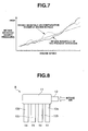
- Fig. 6A is a graph showing a structural feature of the air intake structure of Fig. 1 in terms of length in air intake passage;
- Fig. 6B is a graph showing an effect of the air intake structure of Fig. 1 in terms of pressure of air;
- Fig. 7 is a graph showing the air intake characteristics of the intake air structure of Fig. 1 and the air intake characteristics of a related art intake manifold A as a comparative example shown in Fig. 8, in terms of intake air noise and engine speed;
- Fig. 8 is an explanatory view of the intake manifold A as the comparative example;
- Fig. 9A is a graph showing a structural feature of the intake manifold A of Fig. 8, in terms of length in air intake passage;
- Fig. 9B is a graph showing an effect of the intake manifold A of Fig. 8, in terms of pressure of air;
- Fig. 10 is an explanatory view of another related art intake manifold B as a comparative example;
- Fig. 11A is a graph showing a structural feature of the intake manifold A of Fig. 10, in terms of length in air intake passage;
- Fig. 11B is a graph showing an effect of the intake manifold A of Fig. 10, in terms of pressure of air;
- Fig. 12 is an explanatory view of a further related art intake manifold C as a comparative example;
- Fig. 13A is a graph showing a structural feature of the intake manifold A of Fig. 12, in terms of length in air intake passage;
- Fig. 13B is a graph showing an effect of the intake manifold A of Fig. 12, in terms of pressure of air; and
- Fig. 14 is an explanatory view of another embodiment of the air intake structure according to the present invention.
-
- Referring now to Figs. 1 to 4 of the drawings, an embodiment of an air intake structure of an internal combustion engine is illustrated including
intake manifold 1. The internal combustion engine is an inline four-cylinder engine.Intake manifold 1 is made of plastic or the like. As shown in Fig. 1 to Fig. 4,intake manifold 1 includesintake air collector 2 which is elongate and extends along a row of cylinders of enginemain body 8. Intakeair inducting pipe 3 is connected withintake air collector 2. Fourbranch pipes intake air collector 2. Through each branch pipe, intake air is supplied to each cylinder of the engine main body. More specifically, first, second, third, and fourth cylinders C1, C2, C3, C4 are supplied with intake air throughbranch pipes - Through intake
air inducting pipe 3, intake air is inducted intointake air collector 2. Intakeair inducting pipe 3 is connected withintake air collector 2 at a side surface opposite to a side surface at whichbranch pipes 4a to 4d are connected, and on one end side (or left side in Fig. 1) ofintake air collector 2 in a longitudinal direction of the intake air collector. - Through each
branch pipe 4a to 4d, intake air withinintake air collector 2 is inducted to an intake air entrance (not shown) of the corresponding cylinder C1, C2, C3, C4. One end section of each branch pipe extends generally in the same direction to be connected withintake air collector 2. The side surface F at which eachbranch pipe 4a to 4d is connected as shown in Fig. 2 and Fig. 3 is formed extending generally along a vertical direction of engine main body 8 (i.e., generally along a vertical direction in Fig. 3). Eachbranch pipe 4at-o 4d is formed to be generally U-shaped as a whole and extends from the intake air entrance opened on the side surface of enginemain body 8 toward an upper side of enginemain body 8. Therefore,intake air collector 2 is located above enginemain body 8. The other end section of eachbranch pipe 4a to 4d is connected with each other byflange 5. - As shown in Fig. 4 and Fig. 5, intake
air inducting pipe 3 has intake air inductingpipe opening section 6 at which intakeair inducting pipe 3 and intakeair collector 2 is connected each other. Intake air inductingpipe opening section 6 extends along the longitudinal direction ofintake air collector 2. Intake air inductingpipe opening section 6 is also located between orbridges branch pipe 4a which is located on one end side ofintake air collector 2 andbranch pipe 4b which is located adjacent to branchpipe 4a, on a plane of Figs. 1 and 2. More specifically, intake air inductingpipe opening section 6 is formed to be located between or bridgebranch pipe opening 7a which is a junction (section) connectingbranch pipe 4a withintake air collector 2 andbranch pipe opening 7b which is the junction connectingbranch pipe 4b withintake air collector 2, in the longitudinal direction ofintake air collector 2. Fig. 5 is a schematic plan view showing a locational configuration including intakeair inducting pipe 3,intake air collector 2 and eachbranch pipe 4a to 4d. - Furthermore, intake air inducting
pipe opening section 6 has an axis (not shown) which is directed tobranch pipe 4d which is nearly located on the other end side (or right side in Fig. 1) ofintake air collector 2. More specifically, the axis of intake air inductingpipe opening section 6 is inclined to an axis (not shown) of branch pipe 4 as indicated by an arrow in Fig. 5, on a plane of Fig. 5. The axis of intake air inductingpipe opening section 6 is also formed to be directed to branchpipe opening section 7d which is a junction (section) connectingbranch pipe 4d withintake air collector 2. Additionally, 7c denotes a branch pipe opening section which is a junction (section) connectingbranch pipe 4c withintake air collector 2. - In such an
intake manifold 1 of this embodiment, the substantial length of intake air passage becomes longer as the junction (section) betweenintake air collector 2 and the branch pipe is located far from intake air inductingpipe opening section 6 in the longitudinal direction ofintake air collector 2. The "intake air passage" means a passage through which intake air flows, formed in the air intake structure. However, intakeair inducting pipe 3 is connected withintake air collector 2 at a location betweenbranch pipe 4a andbranch pipe 4b in the longitudinal direction ofintake air collector 2, so that it is possible to decrease a difference in substantial length of the intake air passage among respective cylinders. - The axis of intake air inducting
pipe opening section 6 is directed tobranch pipe 4d located the farthest from intake air inductingpipe opening section 6 in the longitudinal direction ofintake air collector 2. Therefore, a bend of the intake air inducted from intake air inductingpipe opening section 6 to the branch pipe is increased as,the branch pipe comes close to intake air inductingpipe opening section 6 in the longitudinal direction ofintake air collector 2. A pressure loss (or bend loss) generated by the bend of intake air is relatively increased as branch pipe 4 comes close to intake air inductingpipe opening section 6. - The length from the junction between the branch pipe and
intake air collector 2 to intake air inductingpipe opening section 6 become longer as the junction between branch pipe 4 andintake air collector 2 becomes far from intake air inductingpipe opening section 6. Accordingly, a pressure loss (or length loss) generated by the length of the intake air is relatively increased as the branch pipe is far from intake air inductingpipe opening section 6. - That is to say, in
intake manifold 1 of this embodiment, the substantial lengths of the intake air passages for the respective cylinders do not become equal as shown in Fig. 6A. However, peak values of pressure wave or peak values of air pressure generated by the respective cylinders delicately differ from each other, and differences in pressure peak value among the respective cylinders can be decreased under the influence of the bend loss and the length loss described above as shown in Fig. 6B. Therefore, this embodiment provides the almost same effect as that in a case (as shown in Figs. 11A and 11B as discussed after) that the substantial lengths of the intake air passages for the respective cylinders are equal to each other so that intake air noise can become clear. - Furthermore, differences in the substantial lengths of the intake air passages for the respective cylinders are decreased so that the intake air noise (or sound pressure) generated by differences in the lengths of the intake air passages for the respective cylinders can be effectively decreased as shown in Fig. 7. Additionally, in
intake manifold 1 of this embodiment, the sound pressure increases as an engine speed of an engine rises, so that a driver does not receive uncomfortable feeling. In Fig. 7, a solid line indicates measurement result of the intake air noise of the intake manifold of this embodiment, and a dotted line indicates measurement result of another intake manifold A which is a comparative example as shown in Fig. 8 which will be discussed after. - Here, intake manifold A is different from above-described
intake manifold 1 of this embodiment only in location at which the connecting section of intakeair inducting pipe 13 is connected tointake air collector 11. As shown in Fig. 8, intake manifold A has a common or usual configuration in which intakeair inducting pipe 13 is connected to one end section ofintake air collector 11, and eachbranch pipe 10a to 10d is connected to one side surface ofintake air collector 11. Therefore, in this intake manifold A, the substantial lengths of the intake air passages for respective cylinders are not equal, and the peak values of pressure waves generated by the cylinders are not equal to each other as shown in Figs. 9A and 9B. Furthermore, in intake manifold A, sound pressure varies with the engine speed as apparent from Fig. 7 so that the driver may receive uncomfortable feeling. - In intake manifold B as shown in Fig. 10 in which each
branch pipe 20 is three-dimensionally independent, generally the same substantial length or distance from the opening section of thebranch pipe 20 to the opening section of intakeair inducting pipe 23 is obtained for therespective branch pipes 20. Therefore, it is possible to make the substantial lengths of the intake air passages for the respective cylinders generally equal as shown in Fig. 11A. Furthermore, it is possible to make pressure wave generated from each cylinder uniform as shown in Fig. 11B. However, in such an intake manifold, a configuration becomes complicated, thereby raising problems such as limitation in manufacturing method (molding is impossible), lowering in productivity, increase in a production cost and increase in weight. Additionally, intake manifold B constructed of intakeair inducting pipe 23,intake air collector 21 and eachbranch pipe 20 becomes larger in size there by causing deterioration in mount ability to a vehicle or the like. - In contrast to intake manifold B, according to the present invention, it is possible to arrange all
branch pipes 4a to 4d in a row along the longitudinal direction ofintake air collector 2, so that, it is possible to manufactureintake manifold 1 by using a manufacturing method that is the same as that for intake manifold A as shown in Fig. 8 and different to that for intake manifold B as shown in Fig. 10, i.e., by using molding. Therefore, productivity of the intake manifold is not sacrificed. - In intake manifold C as shown in Fig. 12, intake
air inducting pipe 33 is connected tointake air collector 31 near the center of the longitudinal direction ofintake air collector 31. Eachbranch pipe 30 is connected to a surface that is opposite to a surface at which intakeair inducting pipe 33 is connected. In this case, it is possible to decrease the differences in substantial length of the intake air passages among respective branch pipes (whose lengths are approximately the same) as shown in Fig. 13A. However, a width (dimension in vertical direction in Fig. 12) of intake manifold C including intakeair inducting pipe 33,intake air collector 31 andbranch pipes 30 becomes relatively large, thereby causing degradation of the mount ability to the vehicle or the like. Additionally, the peak values of pressure waves generated by the cylinders are classified into two values as shown in Fig. 13B, so that the tone of intake air noise dulls. Therefore, it is impossible to make the intake air noise clear as same as noise generated byintake manifold 1 of this embodiment. - In contrast to intake manifold C as shown in Fig. 12, according to the present invention, it is not necessary to make the width of
intake manifold 1 large, so that mount ability to the vehicle is not also sacrificed. - Further, the intake air structure of this invention is not limited to the above-discussed embodiment. Accordingly, the axis of intake air inducting
pipe opening section 6 located at one end side of the intake air collector is directed to the junction between the intake air collector and the branch pipe connected to the intake air collector and located the farthest from the one end side of the intake air collector, and the intake air inducting pipe opening section is located betweenopening section 7a offirst branch pipe 4a placed the nearest to the one end side of the intake air collector andopening section 7b ofsecond branch pipe 4b placed adjacent to thefirst branch pipe 4a in the longitudinal direction of the intake air collector. Therefore, intakeair inducting pipe 3 may be connected withintake air collector 2 from the above side ofintake manifold 1 in a vertical direction in Fig. 1 to Fig. 3, as illustrated in Fig. 14 showing the air intake structure as another embodiment of the present invention. That is to say, it is possible to connect intakeair inducting pipe 3 withintake air collector 2 from the vertical direction or a horizontal direction in Fig. 1 to Fig. 3. - Furthermore, the principle of the air intake structure according to this invention is applicable not only to the inline four-cylinder engine but also to engines each of which includes at least one group of the cylinders in which intake manifold is provided for each group of cylinders. More specifically, it is applicable to a first engine having the number (multiple of 4) of cylinders (eight cylinders, twelve cylinders and the like) in which one intake manifold is provided for four cylinders, a second engine having the number (multiple of 3) of cylinders (three cylinders, six cylinders, nine cylinders and the like) in which one intake manifold is provided for three cylinders, and a third engine having the number (multiple of 5) of cylinders (five cylinders, ten cylinders and the like) in which one intake manifold is provided for five cylinders.
- In this case, the second and third engines have a little effect for decreasing intake air noise as composed with the first engine. However, these engines can obtain good effects for decreasing intake air noise as compared with engine provided with the above-mentioned intake manifold A.
- Additionally, in the above-mentioned embodiment, the axis of intake air inducting
pipe opening section 6 located at one end side of the intake air collector is directed to the junction between the branch pipe connected to the intake air collector and the intake air collector located the farthest from the one end side of the intake air collector, and is located betweenopening section 7a offirst branch pipe 4a placed the nearest to the one end section of the intake air collector andopening section 7b ofsecond branch pipe 4b placed adjacent to the first branch pipe in the longitudinal direction of the intake air collector. However, in an inline engine having four or more cylinders (for example, six cylinders or eight cylinders), the intake air inducting pipe opening section may be formed such that its axis is directed to the branch pipe (for example,branch pipe 4c placed secondly nearest to the other end side of the intake air collector) placed at the other end side of the longitudinal direction of the intake air collector in the longitudinal direction, and to be placed between the one branch pipe placed in the one end side of the intake air collector and the next branch pipe placed adjacent to the one branch pipe (for example, betweenbranch pipe 4b placed secondly nearest to the one end side andbranch pipe 4c placed thirdly nearest to the one end side of the intake air collector) in the longitudinal direction of the intake air collector. - Hereinafter, technical ideas according to the present invention will be summarized with effects obtained thereby.
- (1) The air intake structure of an internal combustion engine, includes an intake air collector having first and second end sides which are longitudinally opposite to each other. An intake air inducting pipe is connected to the intake air collector. A plurality of branch pipes are connected to the intake air collector and communicated respectively with intake air entrances of cylinders of the engine. Each branch pipe is connected through a junction section of the branch pipe to the intake air collector. The junction sections of the branch pipes are arranged or aligned along a longitudinal direction of the intake air collector. In this arrangement, the intake air inducting pipe having an opening section serving as the junction section. The opening section is located between a first branch pipe located at the first end side of the intake air inducting pipe and a second branch pipe located adjacent to the first branch pipe in a longitudinal direction of the intake air collector, and having an axis which is directed to a third branch pipe located at the second end side of the intake air collector. With this air intake structure, the substantial length of the intake air passage is not equal among respective cylinders; however, the pressure wave of the intake air generated from each cylinder can become similar to the pressure wave of the intake air generated from each cylinder in a case that the substantial length of the intake air passage is equal among respective cylinders. Therefore, it is possible to obtain the same advantage with such a case. In other words, by virtue of the air intake structure of the present invention, the differences in substantial length of the intake air passages for respective cylinders are reduced. Additionally, an air flow friction generated owing to curve of intake air increases as the branch pipe becomes closer to the intake air inducting pipe opening section. Thus, according to the present invention, although the substantial lengths of the intake air passages are not equal among the intake air passages for the respective cylinders, pressure wave of intake air generated from each cylinder can become similar to the pressure wave of the intake air generated from each cylinder in a case that the substantial length of the intake air passage is equal for each cylinder.
- (2) In the air intake structure described in (1), the cylinders of the engine include at least one group of cylinders, wherein the intake manifold includes the intake air collector provided for each group of cylinders, the branch pipes of a number corresponding to a number of cylinders in each group of cylinders, and the intake air inducting pipe.
- (3) In the air intake structure described in (2), more specifically, each group of cylinders includes four cylinders.
- (4) In the air intake structure described in (2), more specifically, each group of cylinders includes three cylinders.
-
- The entire contents of Japanese Patent Application No. P2003-351583, filed October 10, 2003, are incorporated herein by reference.
- Although the invention has been described above by reference to certain embodiments and examples of the invention, the invention is not limited to the embodiments and examples described above. Modifications and variations of the embodiments and examples described above will occur to those skilled in the art, in light of the above teachings. The scope of the invention is defined with reference to the following claims.
Claims (5)
- An air intake structure of an internal combustion engine, comprising:wherein the intake air inducting pipe having an opening section (6) serving as the junction section, the opening section being located between a first branch pipe (4a) located at the first end side of the intake air collector and a second branch pipe (4b) located adjacent to the first branch pipe in a longitudinal direction of the intake air collector, and having an axis which is directed to a third branch pipe (4d) located at the second end side of the intake air collector.an intake air collector (2) having first and second end sides which are longitudinally opposite to each other;an intake air inducting pipe (3) connected to the intake air collector; anda plurality of branch pipes (4a-4d) connected to the intake air collector and communicated respectively with intake air entrances of cylinders (C1-C4) of the engine, each branch pipe being connected through a junction section of the branch pipe to the intake air collector, the junction sections of the branch pipes being arranged along a longitudinal direction of the intake air collector,
- An air intake structure as claimed in Claim 1, wherein the intake air collector (2), the intake air inducting pipe (3) and the branch pipes (4a-4d) constitute an intake manifold (1).
- An air intake structure as claimed in Claim 2, wherein the cylinders (C1-C4) of the engine include at least one group of cylinders, wherein the intake manifold includes the intake air collector provided for each group of cylinders, the branch pipes of a number corresponding to a number of cylinders in each group of cylinders, and the intake air inducting pipe.
- An air intake structure as claimed in Claim 3, wherein each group of cylinders (C1-C4) includes four cylinders.
- An air intake structure as claimed in Claim 3, wherein each group of cylinders (C1-C4) includes three cylinders.
Applications Claiming Priority (2)
| Application Number | Priority Date | Filing Date | Title |
|---|---|---|---|
| JP2003351583A JP4214883B2 (en) | 2003-10-10 | 2003-10-10 | Intake structure of internal combustion engine |
| JP2003351583 | 2003-10-10 |
Publications (3)
| Publication Number | Publication Date |
|---|---|
| EP1522716A2 true EP1522716A2 (en) | 2005-04-13 |
| EP1522716A3 EP1522716A3 (en) | 2010-04-28 |
| EP1522716B1 EP1522716B1 (en) | 2012-08-01 |
Family
ID=34309272
Family Applications (1)
| Application Number | Title | Priority Date | Filing Date |
|---|---|---|---|
| EP04023975A Expired - Fee Related EP1522716B1 (en) | 2003-10-10 | 2004-10-07 | Air intake structure of internal combustion engine |
Country Status (4)
| Country | Link |
|---|---|
| US (1) | US6920858B2 (en) |
| EP (1) | EP1522716B1 (en) |
| JP (1) | JP4214883B2 (en) |
| CN (1) | CN100339588C (en) |
Cited By (1)
| Publication number | Priority date | Publication date | Assignee | Title |
|---|---|---|---|---|
| FR2920487A1 (en) * | 2007-09-05 | 2009-03-06 | Renault Sas | Air distributor for supercharged internal combustion engine, has plenum provided with air inlet and opening in conduits, where two conduits having different geometries such that distances separating inlet from outlets of conduits are equal |
Families Citing this family (4)
| Publication number | Priority date | Publication date | Assignee | Title |
|---|---|---|---|---|
| US7401590B2 (en) * | 2006-10-09 | 2008-07-22 | Harley-Davidson Motor Company Group, Inc. | Active air intake for an engine |
| JP4906549B2 (en) * | 2007-03-15 | 2012-03-28 | 本田技研工業株式会社 | Intake manifold for multi-cylinder internal combustion engines |
| CN103603755A (en) * | 2013-12-05 | 2014-02-26 | 安徽江淮汽车股份有限公司 | Gas inlet manifold of gasoline engine for vehicle |
| JP2019157774A (en) * | 2018-03-14 | 2019-09-19 | アイシン精機株式会社 | Intake device and manufacturing method of intake device |
Family Cites Families (9)
| Publication number | Priority date | Publication date | Assignee | Title |
|---|---|---|---|---|
| JP2850596B2 (en) * | 1991-10-14 | 1999-01-27 | トヨタ自動車株式会社 | Intake device for multi-cylinder internal combustion engine |
| DE59209528D1 (en) * | 1992-08-22 | 1998-11-19 | Porsche Ag | INTERNAL COMBUSTION ENGINE WITH AN INTAKE SYSTEM |
| JPH08501852A (en) * | 1992-08-22 | 1996-02-27 | ドクトル・インゲニーウル・ハー・ツェー・エフ・ポルシェ・アクチェンゲゼルシャフト | Intake device for internal combustion engine |
| EP0656994B1 (en) * | 1992-08-22 | 1996-05-08 | Dr.Ing.h.c. F. Porsche Aktiengesellschaft | Air-aspiration system for an internal-combustion engine |
| JP3383337B2 (en) | 1992-12-14 | 2003-03-04 | 株式会社エッチ・ケー・エス | Intake collector |
| JPH08105359A (en) | 1994-10-07 | 1996-04-23 | Nissan Motor Co Ltd | Internal combustion engine intake manifold device |
| JP3562031B2 (en) | 1995-06-08 | 2004-09-08 | 日産自動車株式会社 | Rocker cover integrated with intake manifold for internal combustion engine |
| DE19803804A1 (en) * | 1998-01-31 | 1999-08-05 | Volkswagen Ag | Suction system for supplying combustion air to an internal combustion engine |
| JP2002168153A (en) * | 2000-12-01 | 2002-06-14 | Denso Corp | Air intake device for internal combustion engine |
-
2003
- 2003-10-10 JP JP2003351583A patent/JP4214883B2/en not_active Expired - Fee Related
-
2004
- 2004-10-07 US US10/959,579 patent/US6920858B2/en not_active Expired - Fee Related
- 2004-10-07 EP EP04023975A patent/EP1522716B1/en not_active Expired - Fee Related
- 2004-10-10 CN CNB2004100849344A patent/CN100339588C/en not_active Expired - Fee Related
Non-Patent Citations (1)
| Title |
|---|
| None |
Cited By (1)
| Publication number | Priority date | Publication date | Assignee | Title |
|---|---|---|---|---|
| FR2920487A1 (en) * | 2007-09-05 | 2009-03-06 | Renault Sas | Air distributor for supercharged internal combustion engine, has plenum provided with air inlet and opening in conduits, where two conduits having different geometries such that distances separating inlet from outlets of conduits are equal |
Also Published As
| Publication number | Publication date |
|---|---|
| EP1522716A3 (en) | 2010-04-28 |
| CN100339588C (en) | 2007-09-26 |
| JP2005113852A (en) | 2005-04-28 |
| CN1605742A (en) | 2005-04-13 |
| JP4214883B2 (en) | 2009-01-28 |
| EP1522716B1 (en) | 2012-08-01 |
| US20050076872A1 (en) | 2005-04-14 |
| US6920858B2 (en) | 2005-07-26 |
Similar Documents
| Publication | Publication Date | Title |
|---|---|---|
| US6920858B2 (en) | Air intake structure of internal combustion engine | |
| US6038855A (en) | Collector device for the primary pipes of an exhaust manifold | |
| JP2008223738A (en) | Intake manifold for multi-cylinder internal combustion engine | |
| US6994065B2 (en) | Intake arrangement for internal combustion engine | |
| CN216111067U (en) | Air inlet pipe of engine | |
| JP4075761B2 (en) | Intake device for internal combustion engine | |
| US8627661B2 (en) | Turbocharger exhaust arrangement | |
| JPH0618033Y2 (en) | Engine exhaust manifold structure | |
| JP3081441B2 (en) | Engine intake manifold structure | |
| JP2005113853A (en) | Intake structure for internal combustion engine | |
| JP2813190B2 (en) | Exhaust system for multi-cylinder engine | |
| JP2000161163A (en) | Structure of inertia supercharging intake manifold for multiple cylinder internal combustion engine | |
| JP2525001B2 (en) | Engine intake system | |
| JP3062257B2 (en) | Engine intake system | |
| US20040083725A1 (en) | Equal length crossover pipe exhaust system | |
| JP3485156B2 (en) | Structure of Inertial Supercharged Intake Manifold for Multi-Cylinder Internal Combustion Engine | |
| JPH0240021A (en) | Intake structure of v-engine | |
| JPS63314358A (en) | Intake manifold for internal combustion engine | |
| JPH0430337Y2 (en) | ||
| JPH0528378Y2 (en) | ||
| JP2641949B2 (en) | Inertial supercharged intake manifold for internal combustion engines | |
| JP2970230B2 (en) | Dual exhaust pipe for vehicles | |
| JP2009156149A (en) | Intake manifold | |
| CN113818977A (en) | Air inlet pipe of engine | |
| JP2828333B2 (en) | Engine intake structure |
Legal Events
| Date | Code | Title | Description |
|---|---|---|---|
| PUAI | Public reference made under article 153(3) epc to a published international application that has entered the european phase |
Free format text: ORIGINAL CODE: 0009012 |
|
| 17P | Request for examination filed |
Effective date: 20041007 |
|
| AK | Designated contracting states |
Kind code of ref document: A2 Designated state(s): AT BE BG CH CY CZ DE DK EE ES FI FR GB GR HU IE IT LI LU MC NL PL PT RO SE SI SK TR |
|
| AX | Request for extension of the european patent |
Extension state: AL HR LT LV MK |
|
| PUAL | Search report despatched |
Free format text: ORIGINAL CODE: 0009013 |
|
| AK | Designated contracting states |
Kind code of ref document: A3 Designated state(s): AT BE BG CH CY CZ DE DK EE ES FI FR GB GR HU IE IT LI LU MC NL PL PT RO SE SI SK TR |
|
| AX | Request for extension of the european patent |
Extension state: AL HR LT LV MK |
|
| RIC1 | Information provided on ipc code assigned before grant |
Ipc: F02M 35/10 20060101AFI20041111BHEP Ipc: F02M 35/104 20060101ALI20100323BHEP Ipc: F02M 35/112 20060101ALI20100323BHEP |
|
| AKX | Designation fees paid |
Designated state(s): DE FR GB |
|
| 17Q | First examination report despatched |
Effective date: 20110311 |
|
| GRAP | Despatch of communication of intention to grant a patent |
Free format text: ORIGINAL CODE: EPIDOSNIGR1 |
|
| GRAS | Grant fee paid |
Free format text: ORIGINAL CODE: EPIDOSNIGR3 |
|
| GRAA | (expected) grant |
Free format text: ORIGINAL CODE: 0009210 |
|
| AK | Designated contracting states |
Kind code of ref document: B1 Designated state(s): DE FR GB |
|
| REG | Reference to a national code |
Ref country code: GB Ref legal event code: FG4D |
|
| RAP1 | Party data changed (applicant data changed or rights of an application transferred) |
Owner name: NISSAN MOTOR CO., LTD. |
|
| REG | Reference to a national code |
Ref country code: DE Ref legal event code: R096 Ref document number: 602004038704 Country of ref document: DE Effective date: 20120927 |
|
| PLBE | No opposition filed within time limit |
Free format text: ORIGINAL CODE: 0009261 |
|
| STAA | Information on the status of an ep patent application or granted ep patent |
Free format text: STATUS: NO OPPOSITION FILED WITHIN TIME LIMIT |
|
| 26N | No opposition filed |
Effective date: 20130503 |
|
| REG | Reference to a national code |
Ref country code: DE Ref legal event code: R097 Ref document number: 602004038704 Country of ref document: DE Effective date: 20130503 |
|
| PGFP | Annual fee paid to national office [announced via postgrant information from national office to epo] |
Ref country code: GB Payment date: 20131002 Year of fee payment: 10 Ref country code: FR Payment date: 20131009 Year of fee payment: 10 Ref country code: DE Payment date: 20131002 Year of fee payment: 10 |
|
| REG | Reference to a national code |
Ref country code: DE Ref legal event code: R119 Ref document number: 602004038704 Country of ref document: DE |
|
| GBPC | Gb: european patent ceased through non-payment of renewal fee |
Effective date: 20141007 |
|
| PG25 | Lapsed in a contracting state [announced via postgrant information from national office to epo] |
Ref country code: GB Free format text: LAPSE BECAUSE OF NON-PAYMENT OF DUE FEES Effective date: 20141007 Ref country code: DE Free format text: LAPSE BECAUSE OF NON-PAYMENT OF DUE FEES Effective date: 20150501 |
|
| REG | Reference to a national code |
Ref country code: FR Ref legal event code: ST Effective date: 20150630 |
|
| PG25 | Lapsed in a contracting state [announced via postgrant information from national office to epo] |
Ref country code: FR Free format text: LAPSE BECAUSE OF NON-PAYMENT OF DUE FEES Effective date: 20141031 |