EP1522664B1 - Hebelartige Verschlussvorrichtung, insbesondere für Lastkraftwagen, Anhänger oder dergleichen - Google Patents
Hebelartige Verschlussvorrichtung, insbesondere für Lastkraftwagen, Anhänger oder dergleichen Download PDFInfo
- Publication number
- EP1522664B1 EP1522664B1 EP04022943A EP04022943A EP1522664B1 EP 1522664 B1 EP1522664 B1 EP 1522664B1 EP 04022943 A EP04022943 A EP 04022943A EP 04022943 A EP04022943 A EP 04022943A EP 1522664 B1 EP1522664 B1 EP 1522664B1
- Authority
- EP
- European Patent Office
- Prior art keywords
- door
- lever
- spring
- rod
- spacer
- Prior art date
- Legal status (The legal status is an assumption and is not a legal conclusion. Google has not performed a legal analysis and makes no representation as to the accuracy of the status listed.)
- Expired - Lifetime
Links
- 125000006850 spacer group Chemical group 0.000 claims abstract description 13
- 238000003466 welding Methods 0.000 claims description 2
- 230000014759 maintenance of location Effects 0.000 description 7
- 238000006243 chemical reaction Methods 0.000 description 3
- 230000009471 action Effects 0.000 description 2
- 230000008878 coupling Effects 0.000 description 2
- 238000010168 coupling process Methods 0.000 description 2
- 238000005859 coupling reaction Methods 0.000 description 2
- 238000009434 installation Methods 0.000 description 2
- 230000000670 limiting effect Effects 0.000 description 2
- 238000000034 method Methods 0.000 description 2
- 230000002159 abnormal effect Effects 0.000 description 1
- 230000004323 axial length Effects 0.000 description 1
- 230000000295 complement effect Effects 0.000 description 1
- 238000006073 displacement reaction Methods 0.000 description 1
- 230000000694 effects Effects 0.000 description 1
- 230000007246 mechanism Effects 0.000 description 1
- 230000004048 modification Effects 0.000 description 1
- 238000012986 modification Methods 0.000 description 1
- 230000008569 process Effects 0.000 description 1
- 230000000717 retained effect Effects 0.000 description 1
Images

Classifications
-
- E—FIXED CONSTRUCTIONS
- E05—LOCKS; KEYS; WINDOW OR DOOR FITTINGS; SAFES
- E05B—LOCKS; ACCESSORIES THEREFOR; HANDCUFFS
- E05B83/00—Vehicle locks specially adapted for particular types of wing or vehicle
- E05B83/02—Locks for railway freight-cars, freight containers or the like; Locks for the cargo compartments of commercial lorries, trucks or vans
- E05B83/08—Locks for railway freight-cars, freight containers or the like; Locks for the cargo compartments of commercial lorries, trucks or vans with elongated bars for actuating the fastening means
- E05B83/10—Rotary bars
-
- E—FIXED CONSTRUCTIONS
- E05—LOCKS; KEYS; WINDOW OR DOOR FITTINGS; SAFES
- E05B—LOCKS; ACCESSORIES THEREFOR; HANDCUFFS
- E05B13/00—Devices preventing the key or the handle or both from being used
- E05B13/002—Devices preventing the key or the handle or both from being used locking the handle
-
- E—FIXED CONSTRUCTIONS
- E05—LOCKS; KEYS; WINDOW OR DOOR FITTINGS; SAFES
- E05B—LOCKS; ACCESSORIES THEREFOR; HANDCUFFS
- E05B15/00—Other details of locks; Parts for engagement by bolts of fastening devices
- E05B15/04—Spring arrangements in locks
- E05B2015/0403—Wound springs
- E05B2015/0406—Wound springs wound in a cylindrical shape
- E05B2015/041—Wound springs wound in a cylindrical shape loaded perpendicular to cylinder axis
Definitions
- the present invention relates to a lever-type fastening device particularly for the door of the body of trucks, trailers and the like.
- Locks for the doors of bodies of trucks are known and widely used which are constituted by at least one articulation rod that is supported so that it can rotate along the door and is provided, at its lower end, with an actuation lever for opening and closing.
- the actuation lever which is usually arranged horizontally, is provided with a sort of lug that is substantially pawl-shaped: the lever can be turned manually from a closed position, in which it is parallel to the body of the truck and in which the pawl-shaped lug engages in a respective locator that is rigidly coupled to said body, to an open position, in which the lug is disengaged from the locator, thus allowing the free rotation of the door about its pivoting axis and allowing access to the internal compartment of the body.
- each one of the doors remains open, and the respective actuation lever can protrude inadvertently with respect to the plane of said door, constituting both a hindrance and a potential danger for operators.
- US-A-1 835 100 discloses a refrigerator car door securing mechanism comprising a locking bar rotatably mounted in bearing blocks located adjacent the upper and lower edges of the door. Portions of the bar extend beyond the upper and lower edges of the door and each has formed thereon a crank arm with a bearing pin engageable in slotted brackets secured to the car side.
- a torsional strain effect is performed on the bar for maintaining a pressure tending to fully seat the door, in one embodiment, by means of: a bearing block located midway of the ends of the door; a hollow sleeve rotatably mounted to the block through which the locking bar passes; an operating lever secured to the sleeve; and a torsion spring embracing the bar with one end of the spring being anchored to the bar and the other end of the spring being anchored to the sleeve.
- US-A-4 134 281 discloses a door lock comprising an elongated shaft journalled in brackets mounted on a pivoted door and having opposite end cam members engageable in respective keeper members secured to top and bottom parts of a door frame, and a handle connected to a central portion of the shaft and rotatably supported by a housing assembly positioned within an opening formed in the door mid-way between the brackets.
- a handle return spring is interposed between the shaft and the housing to bias the handle towards its nestled position.
- the aim of the present invention is to obviate the above-cited drawbacks, by providing a fastening device for doors of trucks that has improved and reliable operation, i.e., is capable of maintaining the efficiency and duration of the spring for retaining the lever in the closed position.
- an object of the present invention is to provide a fastening device that can be assembled accurately and in a versatile manner.
- Another object of the present invention is to provide a fastening device that is simple, relatively easy to provide in practice, safe in use, effective in operation, and has a relatively low cost.
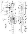
- the reference numeral 1 generally designates a lever-type fastening device particularly for the door of the body of trucks, trailers and the like.
- the device 1 comprises at least one vertical articulation rod 2, which is supported so that it can rotate along a door 3 of the body of the truck, to which at least one actuation lever 4 is rigidly coupled; the lever is arranged horizontally and forms a sort of substantially pawl-shaped lug 5.
- the lever 4 can rotate manually from a position for closing the door 3, in which it is accommodated and retained in a base 6 rigidly coupled to the chassis of the body of the truck (by way of the engagement of a protrusion 7 of the base 6 in a recess 7a of the lever 4) and in which the pawl-shaped lug 5 is engaged in a respective locator 8 that is rigidly coupled to the base 6, to a position for opening the door 3, in which the pawl-shaped lug 5 is disengaged from the locator 8, so that it is possible to turn the door freely about its own pivoting axis and allow access to the loading compartment of the body.
- the base 6 is provided with manually-operated means 9 for locking the lever 4 in the closure position, which are suitable to prevent said lever from disengaging accidentally, leaving the door 3 free to open.
- the fastening device comprises a spring 10 for retaining the lever 4 in the closure position, which is accommodated in a spacer 11 that is fitted coaxially along the articulation rod 2 and is interposed between the lever 4 and the lower edge 12 of the door 3, said spacer being suitable to support the axial load that bears, during operation, on the retention spring 10. Further, by varying the axial dimension of the spacer 11 it is possible to obtain precisely and accurately various assembly configurations that are better suited to the specific applications.
- the actuation lever 4 which is slender and elongated, forms a manual actuation end 13 and is affected, at the opposite end, by a cylindrical transverse through cavity 14, for rigid keying along the lower end of the articulation rod 2. Substantially in the central portion, the lever 4 has a first opening 15 and a second opening 16, which are formed and separated by a sort of bridge 17; moreover, the lever 4 forms, at the second opening 16, an eye 18 for fixing to a complementary eye 19, which is rigidly coupled to the base 6, with customs seals.
- the lever 4 is affected, proximate to the cavity 14, by a transverse through hole 20, whose axis is parallel to the axis of the cavity 14 and which has a circular cross-section and a smaller diameter.
- the base 6 is, for example, fixed to the chassis of the body by means of bolts 21 and lateral welds, is flat and elongated, and is provided with two side walls 22 at the locking means 9; the locator 8 for the pawl-shaped lug 5 of the lever 4 is preferably constituted by a sort of T-shaped element, which is fixed in a lower region to the surface of the base 6.
- the means 9 for locking the lever 4 in the closure position are constituted by a first rocker 23 and a second rocker 24, which are articulated respectively on a first pivot 25 and a second pivot 26, which are fixed, at their ends, to raised portions 27 of the base 6; the first and second rockers 23 and 24 form respectively a first tooth 28 and a second tooth 29, as well as a first profile 30 and a second profile 31, which are mutually kinematically coupled.
- the first and second rockers 23 and 24 are associated with respective torsion springs 32 and 33, which are mounted on the first and second pivots 25 and 26 (see Figures 1 and 2).
- the rockers 23 and 24 are inserted respectively in the first and second openings 15 and 16 and the first and second teeth 28 and 29 stably surround the bridge 17 by way of the action of the torsion springs 32 and 33; the manual pressure applied to the first rocker 23 entails, by way of the coupling of the profiles 30 and 31, the rotation of the first and second rockers 23 and 24 in mutually opposite directions, with consequent disengagement of the teeth 28 and 29 from the bridge 17 and disengagement of the lever 4 from the base 6.
- the spring 10 for retaining the lever 4 ( Figure 3) in the closure position, particularly if the door 3 is open during operations for loading and unloading the compartment of the body, is of the helical torsion type, is fitted coaxially to the rod 2, and is preferably constituted by a small number of turns (the elastic force required is relatively modest and furthermore the space occupation must be minimal).
- the spring has a first end 34, which is rigidly coupled to the spacer 11, and a second end 35, which is rigidly coupled to the lever 4; in particular, the second end 35 is engaged inside the transverse through hole 20.
- the spacer 11, rigidly connected to the lower edge 12 of the door 3, comprises a substantially bell-shaped portion 36, which is mounted coaxially to the rod 2 and forms internally a receptacle 37, which is open downward, for the turns of the retention spring 10; the bell-shaped portion 36 is, in the operating condition, arranged so that the lower rim 38 is in abutment against the upper side of the lever 4, so as to relieve the retention spring 10 from the axial load due to assembly and to the constraining reactions of the structure of the body.
- the bell-shaped portion 36 has an abutment surface 39 for the spring, which is perpendicular to the axis of the rod 2 and is affected by a first circular opening 40 and a second circular opening 41 ( Figure 4) in which the first end 34 of the retention spring 10 is inserted selectively during the installation of the lever 4 in the right or left configuration, respectively.
- the bell-shaped portion 36 of the spacer 11 is extended upward with a substantially tubular portion 42, which is keyed along the rod 2, which in turn is connected to a rectangular fixing plate 43, for example by means of screws 44, to the lower edge 12 of the door 3.
- the bell-shaped portion 36, the tubular portion 42 and the plate 43 are preferably mutually connected by welding.
- the method of use of the device according to the invention is as follows. With the door 3 of the body fastened, the lever 4 is accommodated in the base 6 parallel to the chassis of the body, the pawl-shaped lug 5 is engaged below the locator 8, and the teeth 28 and 29 of the rockers 23 and 24 are closed on the bridge 17.
- said first rocker 23 By applying manual pressure to the surface of the first rocker 23, said first rocker is turned about the axis of the first pivot 25; the coupling between the first profile 30 and the second profile 31 induces the rotation in the opposite direction of the second rocker 24, with consequent disengagement of the bridge 17 from the teeth 28 and 29.
- the lever 4 can thus be turned freely from the closure position to the open position, so as to disengage the pawl-like lug 5 from the respective locator 8.
- the retention spring 10 allows to keep the lever 4 stably and safely in the closed position (i.e., parallel to the door 3): one thus prevents it from protruding during the operations for loading and unloading the body, since it might constitute a hindrance and a potential danger.
- the retention spring 10 constitutes an effective safety measure against accidental angular displacements of the actuation lever 4, which is thus constantly kept substantially parallel to the plane of the door 3 in the correct position of minimum space occupation.
- the spacer 11 can be provided with a variable overall axial length, so that it can be adapted easily to different conditions of application characterized by different assembly configurations and loads.
Landscapes
- Lock And Its Accessories (AREA)
- Seal Device For Vehicle (AREA)
- Superstructure Of Vehicle (AREA)
Claims (7)
- Hebelartige Schließvorrichtung, insbesondere für die Tür von Laderaumkörpern von Lastwagen, Anhängern und dergleichen,
mit mindestens einer Stange (2), die so gehaltert ist, dass sie entlang der Tür (3) verschwenkt werden kann, und mit der mindestens ein Hebel (4) zum Öffnen und Schließen der Tür (3) im rechten Winkel, fest gekoppelt ist, wobei der Hebel (4) von einer Schließposition der Tür (3), in der er mittels eines im wesentlichen klinkenartigen Ansatzes (5) in einen entsprechenden Halter (8) eingreift, der fest mit dem Laderaumkörper unter einer Unterkante (12) der Tür (3) gekoppelt ist, in eine Position zum Öffnen der Tür (3) verschwenkt werden kann, in der der klinkenartige Ansatz (5) außer Eingriff von dem Halter (8) gebracht wird,
mit einer koaxial zu der Stange (2) angeordneten Feder (10) zum Halten des Hebels (4) in der Schließposition, wobei der Feder ein Abstandselement (11) zugeordnet ist, das fest mit der Unterkante (12) der Tür (3) verbunden und zwischen dem Hebel (4) und der Unterkante (12) der Tür (3) angeordnet ist, wodurch eine präzise Platzierung des Hebels (4) gegenüber der Unterkante (12) der Tür (3) und eine Aufnahme der im Betrieb auftretenden und auf die Feder (10) einwirkenden axialen Last ermöglicht wird. - Vorrichtung nach Anspruch 1, dadurch gekennzeichnet, dass die Feder (10) eine schraubenförmige Torsionsfeder ist, deren erstes Ende (34) fest mit dem Abstandselement (11) und deren zweites Ende (35) fest mit dem Hebel (4) gekoppelt ist.
- Vorrichtung nach Anspruch 1 oder 2, dadurch gekennzeichnet, dass der Hebel (4) durch ein quer verlaufendes Durchgangsloch (20) beeinflußt wird, das einen im wesentlichen kreisförmigen Querschnitt hat, und in dem das zweite Ende (35) der Feder (10) angreift.
- Vorrichtung nach einem oder mehreren der vorhergehenden Ansprüche, dadurch gekennzeichnet, dass das Abstandselement (11) einen im wesentlichen glockenförmigen Abschnitt (36) aufweist, der koaxial zur Stange (2) verläuft, mit der Kante (12) der Tür (3) verbunden ist und innen eine Aufnahme (37) für die Feder (10) bildet.
- Vorrichtung nach einem oder mehreren der vorhergehenden Ansprüche, dadurch gekennzeichnet, dass der glockenförmige Abschnitt (36) eine Anlagefläche (39) für die Feder (10) bildet, die durch eine erste kreisförmige Öffnung (40) und eine zweite kreisförmige Öffnung (41) beeinflußt wird, in die das erste Ende (34) der Feder (10) wahlweise eingreift, wenn der Hebel (4) in einer rechten bzw. einer linken Konfiguration installiert wird.
- Vorrichtung nach einem oder mehreren der vorhergehenden Ansprüche, dadurch gekennzeichnet, dass das Abstandselement (11) einen im wesentlichen rohrförmigen Abschnitt (42) aufweist, der koaxial auf der Stange (2) montiert und an einem Ende mit dem glockenförmigen Abschnitt (36) und an dem anderen Ende mit einer Platte (43) zum Befestigen an der Kante (12) der Tür (3) verbunden ist.
- Vorrichtung nach einem oder mehreren der vorhergehenden Ansprüche, dadurch gekennzeichnet, dass der glockenförmige Abschnitt (36), der rohrförmige Abschnitt (42) und die Platte (43) durch Schweißen miteinander verbunden sind.
Applications Claiming Priority (2)
| Application Number | Priority Date | Filing Date | Title |
|---|---|---|---|
| ITBO20030099 | 2003-10-10 | ||
| IT000099U ITBO20030099U1 (it) | 2003-10-10 | 2003-10-10 | Dispositivo di serraggio a leva, particolarmente per il portellone di cassone del camion, rimorchi e simili |
Publications (2)
| Publication Number | Publication Date |
|---|---|
| EP1522664A1 EP1522664A1 (de) | 2005-04-13 |
| EP1522664B1 true EP1522664B1 (de) | 2006-12-20 |
Family
ID=43724261
Family Applications (1)
| Application Number | Title | Priority Date | Filing Date |
|---|---|---|---|
| EP04022943A Expired - Lifetime EP1522664B1 (de) | 2003-10-10 | 2004-09-27 | Hebelartige Verschlussvorrichtung, insbesondere für Lastkraftwagen, Anhänger oder dergleichen |
Country Status (6)
| Country | Link |
|---|---|
| EP (1) | EP1522664B1 (de) |
| AT (1) | ATE348932T1 (de) |
| DE (1) | DE602004003762T2 (de) |
| DK (1) | DK1522664T3 (de) |
| ES (1) | ES2277182T3 (de) |
| IT (1) | ITBO20030099U1 (de) |
Cited By (1)
| Publication number | Priority date | Publication date | Assignee | Title |
|---|---|---|---|---|
| DE202009004481U1 (de) | 2009-03-31 | 2010-08-19 | Future Product Entwicklungs- Und Vertriebsgesellschaft Mbh | Drehstangentürverschluss |
Families Citing this family (4)
| Publication number | Priority date | Publication date | Assignee | Title |
|---|---|---|---|---|
| DE102007056626A1 (de) * | 2007-11-23 | 2009-05-28 | F. Hesterberg & Söhne GmbH & Co KG | Drehstangenverschluss, insbesondere für Schwenktüren von Kraftfahrzeugaufbauten |
| EP2666935A1 (de) * | 2012-05-21 | 2013-11-27 | Pastore & Lombardi S.r.l. | Vorrichtung zum Abschließen der Türen von Fahrzeugen |
| EP2733288B1 (de) | 2012-11-20 | 2019-05-22 | F. Hesterberg & Söhne GmbH & Co. KG | Drehstangenverschluss, insbesondere für Schwenktüren von Kraftfahrzeugaufbauten |
| DE102012111146A1 (de) | 2012-11-20 | 2014-06-05 | F. Hesterberg & Söhne Gmbh & Co. Kg | Drehstangenverschluss, insbesondere für Schwenktüren von Kraftfahrzeugaufbauten |
Family Cites Families (3)
| Publication number | Priority date | Publication date | Assignee | Title |
|---|---|---|---|---|
| US1835100A (en) * | 1927-02-09 | 1931-12-08 | Symington T H & Son Inc | Door securing mechanism |
| US4134281A (en) * | 1977-08-08 | 1979-01-16 | The Eastern Company | Cam-type door lock with recessed handle |
| ATE288981T1 (de) * | 1998-12-22 | 2005-02-15 | Pwp Sa | Drehstangenverschluss, insbesondere für schwenktüren von kraftfahrzeugaufbauten |
-
2003
- 2003-10-10 IT IT000099U patent/ITBO20030099U1/it unknown
-
2004
- 2004-09-27 AT AT04022943T patent/ATE348932T1/de not_active IP Right Cessation
- 2004-09-27 DE DE602004003762T patent/DE602004003762T2/de not_active Expired - Lifetime
- 2004-09-27 ES ES04022943T patent/ES2277182T3/es not_active Expired - Lifetime
- 2004-09-27 EP EP04022943A patent/EP1522664B1/de not_active Expired - Lifetime
- 2004-09-27 DK DK04022943T patent/DK1522664T3/da active
Cited By (1)
| Publication number | Priority date | Publication date | Assignee | Title |
|---|---|---|---|---|
| DE202009004481U1 (de) | 2009-03-31 | 2010-08-19 | Future Product Entwicklungs- Und Vertriebsgesellschaft Mbh | Drehstangentürverschluss |
Also Published As
| Publication number | Publication date |
|---|---|
| ITBO20030099U1 (it) | 2005-04-11 |
| DK1522664T3 (da) | 2007-04-30 |
| ATE348932T1 (de) | 2007-01-15 |
| ES2277182T3 (es) | 2007-07-01 |
| DE602004003762D1 (de) | 2007-02-01 |
| DE602004003762T2 (de) | 2007-10-11 |
| EP1522664A1 (de) | 2005-04-13 |
Similar Documents
| Publication | Publication Date | Title |
|---|---|---|
| CA2403070C (en) | Mortise lock | |
| US7156441B2 (en) | Tailgate counterbalancing hinge | |
| US11499352B2 (en) | Flush handle control | |
| PL177437B1 (pl) | Okno dachowe uchylno-wahadłowe | |
| EP1522664B1 (de) | Hebelartige Verschlussvorrichtung, insbesondere für Lastkraftwagen, Anhänger oder dergleichen | |
| US7543625B2 (en) | Brake device for garage doors and the like, and door assembly including the same | |
| US7195300B2 (en) | Tailgate counterbalancing hinge | |
| CA2518668C (en) | Retrofit tailgate counterbalancing hinge | |
| US4413696A (en) | Latch mechanism for a tiltable cab | |
| US7281747B2 (en) | Tailgate counterbalancing hinge | |
| EP1548215B1 (de) | Hebelartige Verschlussvorrichtung für Türe von Lastkraftwagen, Anhänger oder dergleichen | |
| US2580026A (en) | Lost motion torque transmitting means | |
| US4268073A (en) | Window lever lock | |
| US7213857B2 (en) | Tailgate counterbalancing hinge with bend in torque rod | |
| EP0021743B1 (de) | Schloss für ein schrägstellbares Lastwagenführerhaus und mit derartigen Schlössern ausgerüstete Fahrzeuge | |
| EP1460210A1 (de) | Hebelartige Verschlussvorrichtung, insbesondere für Lastkraftwagen, Anhänger oder dgl. | |
| EP1512815B1 (de) | Schloss für eine Kraftfahrzeugtür | |
| EP0839977B1 (de) | Handhabe mit vereinfachter Sicherheitsbetätigung für Lastwagentüre, Anhängertüre oder ähnliches | |
| US4560026A (en) | Parking system for an articulated tricycle | |
| US4413694A (en) | Lock assembly for a tiltable truck cab | |
| EP1350675A2 (de) | Handschuhfach | |
| EP1612350B1 (de) | Türschliesssystem für Türen an Behältern für Gegenstände | |
| KR100878599B1 (ko) | 화물차용 적재함 사이드 게이트의 개폐 보조장치 | |
| US4413695A (en) | Vehicle with tiltable cab | |
| US2446753A (en) | Door handle assembly |
Legal Events
| Date | Code | Title | Description |
|---|---|---|---|
| PUAI | Public reference made under article 153(3) epc to a published international application that has entered the european phase |
Free format text: ORIGINAL CODE: 0009012 |
|
| AK | Designated contracting states |
Kind code of ref document: A1 Designated state(s): AT BE BG CH CY CZ DE DK EE ES FI FR GB GR HU IE IT LI LU MC NL PL PT RO SE SI SK TR |
|
| AX | Request for extension of the european patent |
Extension state: AL HR LT LV MK |
|
| 17P | Request for examination filed |
Effective date: 20050906 |
|
| AKX | Designation fees paid |
Designated state(s): AT BE BG CH CY CZ DE DK EE ES FI FR GB GR HU IE IT LI LU MC NL PL PT RO SE SI SK TR |
|
| GRAP | Despatch of communication of intention to grant a patent |
Free format text: ORIGINAL CODE: EPIDOSNIGR1 |
|
| GRAS | Grant fee paid |
Free format text: ORIGINAL CODE: EPIDOSNIGR3 |
|
| GRAA | (expected) grant |
Free format text: ORIGINAL CODE: 0009210 |
|
| AK | Designated contracting states |
Kind code of ref document: B1 Designated state(s): AT BE BG CH CY CZ DE DK EE ES FI FR GB GR HU IE IT LI LU MC NL PL PT RO SE SI SK TR |
|
| PG25 | Lapsed in a contracting state [announced via postgrant information from national office to epo] |
Ref country code: AT Free format text: LAPSE BECAUSE OF FAILURE TO SUBMIT A TRANSLATION OF THE DESCRIPTION OR TO PAY THE FEE WITHIN THE PRESCRIBED TIME-LIMIT Effective date: 20061220 Ref country code: SK Free format text: LAPSE BECAUSE OF FAILURE TO SUBMIT A TRANSLATION OF THE DESCRIPTION OR TO PAY THE FEE WITHIN THE PRESCRIBED TIME-LIMIT Effective date: 20061220 Ref country code: RO Free format text: LAPSE BECAUSE OF FAILURE TO SUBMIT A TRANSLATION OF THE DESCRIPTION OR TO PAY THE FEE WITHIN THE PRESCRIBED TIME-LIMIT Effective date: 20061220 Ref country code: PL Free format text: LAPSE BECAUSE OF FAILURE TO SUBMIT A TRANSLATION OF THE DESCRIPTION OR TO PAY THE FEE WITHIN THE PRESCRIBED TIME-LIMIT Effective date: 20061220 Ref country code: SI Free format text: LAPSE BECAUSE OF FAILURE TO SUBMIT A TRANSLATION OF THE DESCRIPTION OR TO PAY THE FEE WITHIN THE PRESCRIBED TIME-LIMIT Effective date: 20061220 Ref country code: CZ Free format text: LAPSE BECAUSE OF FAILURE TO SUBMIT A TRANSLATION OF THE DESCRIPTION OR TO PAY THE FEE WITHIN THE PRESCRIBED TIME-LIMIT Effective date: 20061220 Ref country code: BE Free format text: LAPSE BECAUSE OF FAILURE TO SUBMIT A TRANSLATION OF THE DESCRIPTION OR TO PAY THE FEE WITHIN THE PRESCRIBED TIME-LIMIT Effective date: 20061220 |
|
| REG | Reference to a national code |
Ref country code: GB Ref legal event code: FG4D |
|
| REG | Reference to a national code |
Ref country code: SE Ref legal event code: TRGR |
|
| REG | Reference to a national code |
Ref country code: CH Ref legal event code: EP |
|
| REF | Corresponds to: |
Ref document number: 602004003762 Country of ref document: DE Date of ref document: 20070201 Kind code of ref document: P |
|
| REG | Reference to a national code |
Ref country code: IE Ref legal event code: FG4D |
|
| REG | Reference to a national code |
Ref country code: CH Ref legal event code: NV Representative=s name: ROTTMANN, ZIMMERMANN + PARTNER AG |
|
| PG25 | Lapsed in a contracting state [announced via postgrant information from national office to epo] |
Ref country code: BG Free format text: LAPSE BECAUSE OF FAILURE TO SUBMIT A TRANSLATION OF THE DESCRIPTION OR TO PAY THE FEE WITHIN THE PRESCRIBED TIME-LIMIT Effective date: 20070320 |
|
| PG25 | Lapsed in a contracting state [announced via postgrant information from national office to epo] |
Ref country code: PT Free format text: LAPSE BECAUSE OF FAILURE TO SUBMIT A TRANSLATION OF THE DESCRIPTION OR TO PAY THE FEE WITHIN THE PRESCRIBED TIME-LIMIT Effective date: 20070424 |
|
| REG | Reference to a national code |
Ref country code: DK Ref legal event code: T3 |
|
| ET | Fr: translation filed | ||
| REG | Reference to a national code |
Ref country code: ES Ref legal event code: FG2A Ref document number: 2277182 Country of ref document: ES Kind code of ref document: T3 |
|
| PLBE | No opposition filed within time limit |
Free format text: ORIGINAL CODE: 0009261 |
|
| STAA | Information on the status of an ep patent application or granted ep patent |
Free format text: STATUS: NO OPPOSITION FILED WITHIN TIME LIMIT |
|
| 26N | No opposition filed |
Effective date: 20070921 |
|
| PG25 | Lapsed in a contracting state [announced via postgrant information from national office to epo] |
Ref country code: GR Free format text: LAPSE BECAUSE OF FAILURE TO SUBMIT A TRANSLATION OF THE DESCRIPTION OR TO PAY THE FEE WITHIN THE PRESCRIBED TIME-LIMIT Effective date: 20070321 Ref country code: MC Free format text: LAPSE BECAUSE OF NON-PAYMENT OF DUE FEES Effective date: 20070930 |
|
| PG25 | Lapsed in a contracting state [announced via postgrant information from national office to epo] |
Ref country code: IE Free format text: LAPSE BECAUSE OF NON-PAYMENT OF DUE FEES Effective date: 20070927 |
|
| PG25 | Lapsed in a contracting state [announced via postgrant information from national office to epo] |
Ref country code: EE Free format text: LAPSE BECAUSE OF FAILURE TO SUBMIT A TRANSLATION OF THE DESCRIPTION OR TO PAY THE FEE WITHIN THE PRESCRIBED TIME-LIMIT Effective date: 20061220 |
|
| PG25 | Lapsed in a contracting state [announced via postgrant information from national office to epo] |
Ref country code: CY Free format text: LAPSE BECAUSE OF FAILURE TO SUBMIT A TRANSLATION OF THE DESCRIPTION OR TO PAY THE FEE WITHIN THE PRESCRIBED TIME-LIMIT Effective date: 20061220 Ref country code: LU Free format text: LAPSE BECAUSE OF NON-PAYMENT OF DUE FEES Effective date: 20070927 |
|
| PG25 | Lapsed in a contracting state [announced via postgrant information from national office to epo] |
Ref country code: HU Free format text: LAPSE BECAUSE OF FAILURE TO SUBMIT A TRANSLATION OF THE DESCRIPTION OR TO PAY THE FEE WITHIN THE PRESCRIBED TIME-LIMIT Effective date: 20070621 Ref country code: TR Free format text: LAPSE BECAUSE OF FAILURE TO SUBMIT A TRANSLATION OF THE DESCRIPTION OR TO PAY THE FEE WITHIN THE PRESCRIBED TIME-LIMIT Effective date: 20061220 |
|
| REG | Reference to a national code |
Ref country code: CH Ref legal event code: PFA Owner name: PASTORE & LOMBARDI S.R.L. Free format text: PASTORE & LOMBARDI S.R.L.#VIA DON MINZONI, 3#40057 CADRIANO DI GRANAROLO DELL'EMILIA (BOLOGNA) (IT) -TRANSFER TO- PASTORE & LOMBARDI S.R.L.#VIA DON MINZONI, 3#40057 CADRIANO DI GRANAROLO DELL'EMILIA (BOLOGNA) (IT) |
|
| REG | Reference to a national code |
Ref country code: FR Ref legal event code: PLFP Year of fee payment: 12 |
|
| REG | Reference to a national code |
Ref country code: FR Ref legal event code: PLFP Year of fee payment: 13 |
|
| REG | Reference to a national code |
Ref country code: CH Ref legal event code: PCAR Free format text: NEW ADDRESS: GARTENSTRASSE 28 A, 5400 BADEN (CH) |
|
| REG | Reference to a national code |
Ref country code: FR Ref legal event code: PLFP Year of fee payment: 14 |
|
| PGFP | Annual fee paid to national office [announced via postgrant information from national office to epo] |
Ref country code: FI Payment date: 20170925 Year of fee payment: 14 Ref country code: FR Payment date: 20170922 Year of fee payment: 14 Ref country code: DE Payment date: 20170925 Year of fee payment: 14 Ref country code: GB Payment date: 20170922 Year of fee payment: 14 Ref country code: CH Payment date: 20170926 Year of fee payment: 14 Ref country code: IT Payment date: 20170922 Year of fee payment: 14 |
|
| PGFP | Annual fee paid to national office [announced via postgrant information from national office to epo] |
Ref country code: NL Payment date: 20170925 Year of fee payment: 14 Ref country code: SE Payment date: 20170922 Year of fee payment: 14 Ref country code: DK Payment date: 20170922 Year of fee payment: 14 |
|
| PGFP | Annual fee paid to national office [announced via postgrant information from national office to epo] |
Ref country code: ES Payment date: 20171017 Year of fee payment: 14 |
|
| REG | Reference to a national code |
Ref country code: DE Ref legal event code: R119 Ref document number: 602004003762 Country of ref document: DE |
|
| PG25 | Lapsed in a contracting state [announced via postgrant information from national office to epo] |
Ref country code: FI Free format text: LAPSE BECAUSE OF NON-PAYMENT OF DUE FEES Effective date: 20180927 |
|
| REG | Reference to a national code |
Ref country code: SE Ref legal event code: EUG Ref country code: CH Ref legal event code: PL |
|
| REG | Reference to a national code |
Ref country code: DK Ref legal event code: EBP Effective date: 20180930 |
|
| REG | Reference to a national code |
Ref country code: NL Ref legal event code: MM Effective date: 20181001 |
|
| GBPC | Gb: european patent ceased through non-payment of renewal fee |
Effective date: 20180927 |
|
| PG25 | Lapsed in a contracting state [announced via postgrant information from national office to epo] |
Ref country code: SE Free format text: LAPSE BECAUSE OF NON-PAYMENT OF DUE FEES Effective date: 20180928 |
|
| PG25 | Lapsed in a contracting state [announced via postgrant information from national office to epo] |
Ref country code: NL Free format text: LAPSE BECAUSE OF NON-PAYMENT OF DUE FEES Effective date: 20181001 |
|
| PG25 | Lapsed in a contracting state [announced via postgrant information from national office to epo] |
Ref country code: IT Free format text: LAPSE BECAUSE OF NON-PAYMENT OF DUE FEES Effective date: 20180927 Ref country code: DE Free format text: LAPSE BECAUSE OF NON-PAYMENT OF DUE FEES Effective date: 20190402 |
|
| PG25 | Lapsed in a contracting state [announced via postgrant information from national office to epo] |
Ref country code: CH Free format text: LAPSE BECAUSE OF NON-PAYMENT OF DUE FEES Effective date: 20180930 Ref country code: LI Free format text: LAPSE BECAUSE OF NON-PAYMENT OF DUE FEES Effective date: 20180930 Ref country code: FR Free format text: LAPSE BECAUSE OF NON-PAYMENT OF DUE FEES Effective date: 20180930 |
|
| PG25 | Lapsed in a contracting state [announced via postgrant information from national office to epo] |
Ref country code: GB Free format text: LAPSE BECAUSE OF NON-PAYMENT OF DUE FEES Effective date: 20180927 Ref country code: DK Free format text: LAPSE BECAUSE OF NON-PAYMENT OF DUE FEES Effective date: 20180930 |
|
| REG | Reference to a national code |
Ref country code: ES Ref legal event code: FD2A Effective date: 20191104 |
|
| PG25 | Lapsed in a contracting state [announced via postgrant information from national office to epo] |
Ref country code: ES Free format text: LAPSE BECAUSE OF NON-PAYMENT OF DUE FEES Effective date: 20180928 |