EP1522658B1 - Serrure électrique avec support magnétique de l'élément de couplage - Google Patents
Serrure électrique avec support magnétique de l'élément de couplage Download PDFInfo
- Publication number
- EP1522658B1 EP1522658B1 EP20040023759 EP04023759A EP1522658B1 EP 1522658 B1 EP1522658 B1 EP 1522658B1 EP 20040023759 EP20040023759 EP 20040023759 EP 04023759 A EP04023759 A EP 04023759A EP 1522658 B1 EP1522658 B1 EP 1522658B1
- Authority
- EP
- European Patent Office
- Prior art keywords
- slider
- lock according
- plate
- lock
- notches
- Prior art date
- Legal status (The legal status is an assumption and is not a legal conclusion. Google has not performed a legal analysis and makes no representation as to the accuracy of the status listed.)
- Expired - Lifetime
Links
- 230000008878 coupling Effects 0.000 title claims abstract description 14
- 238000010168 coupling process Methods 0.000 title claims abstract description 14
- 238000005859 coupling reaction Methods 0.000 title claims abstract description 14
- 230000000284 resting effect Effects 0.000 claims abstract 2
- 238000003780 insertion Methods 0.000 claims description 2
- 230000037431 insertion Effects 0.000 claims description 2
- 230000000670 limiting effect Effects 0.000 description 2
- 230000007257 malfunction Effects 0.000 description 2
- 230000002596 correlated effect Effects 0.000 description 1
- 230000000875 corresponding effect Effects 0.000 description 1
- 238000012423 maintenance Methods 0.000 description 1
- 239000000463 material Substances 0.000 description 1
- 239000002184 metal Substances 0.000 description 1
- 238000012986 modification Methods 0.000 description 1
- 230000004048 modification Effects 0.000 description 1
- 238000004804 winding Methods 0.000 description 1
Images


Classifications
-
- E—FIXED CONSTRUCTIONS
- E05—LOCKS; KEYS; WINDOW OR DOOR FITTINGS; SAFES
- E05B—LOCKS; ACCESSORIES THEREFOR; HANDCUFFS
- E05B47/00—Operating or controlling locks or other fastening devices by electric or magnetic means
- E05B47/06—Controlling mechanically-operated bolts by electro-magnetically-operated detents
- E05B47/0676—Controlling mechanically-operated bolts by electro-magnetically-operated detents by disconnecting the handle
- E05B47/0684—Controlling mechanically-operated bolts by electro-magnetically-operated detents by disconnecting the handle radially
- E05B47/0692—Controlling mechanically-operated bolts by electro-magnetically-operated detents by disconnecting the handle radially with a rectilinearly moveable coupling element
-
- E—FIXED CONSTRUCTIONS
- E05—LOCKS; KEYS; WINDOW OR DOOR FITTINGS; SAFES
- E05B—LOCKS; ACCESSORIES THEREFOR; HANDCUFFS
- E05B63/00—Locks or fastenings with special structural characteristics
- E05B63/0065—Operating modes; Transformable to different operating modes
- E05B63/0069—Override systems, e.g. allowing opening from inside without the key, even when locked from outside
-
- E—FIXED CONSTRUCTIONS
- E05—LOCKS; KEYS; WINDOW OR DOOR FITTINGS; SAFES
- E05B—LOCKS; ACCESSORIES THEREFOR; HANDCUFFS
- E05B15/00—Other details of locks; Parts for engagement by bolts of fastening devices
- E05B15/04—Spring arrangements in locks
- E05B2015/0496—Springs actuated by cams or the like
-
- E—FIXED CONSTRUCTIONS
- E05—LOCKS; KEYS; WINDOW OR DOOR FITTINGS; SAFES
- E05B—LOCKS; ACCESSORIES THEREFOR; HANDCUFFS
- E05B47/00—Operating or controlling locks or other fastening devices by electric or magnetic means
- E05B47/0001—Operating or controlling locks or other fastening devices by electric or magnetic means with electric actuators; Constructional features thereof
- E05B2047/0014—Constructional features of actuators or power transmissions therefor
- E05B2047/0015—Output elements of actuators
- E05B2047/0016—Output elements of actuators with linearly reciprocating motion
-
- E—FIXED CONSTRUCTIONS
- E05—LOCKS; KEYS; WINDOW OR DOOR FITTINGS; SAFES
- E05B—LOCKS; ACCESSORIES THEREFOR; HANDCUFFS
- E05B47/00—Operating or controlling locks or other fastening devices by electric or magnetic means
- E05B47/0001—Operating or controlling locks or other fastening devices by electric or magnetic means with electric actuators; Constructional features thereof
- E05B2047/0014—Constructional features of actuators or power transmissions therefor
- E05B2047/0018—Details of actuator transmissions
- E05B2047/0026—Clutches, couplings or braking arrangements
- E05B2047/0028—Clutches, couplings or braking arrangements using electromagnetic means
-
- E—FIXED CONSTRUCTIONS
- E05—LOCKS; KEYS; WINDOW OR DOOR FITTINGS; SAFES
- E05B—LOCKS; ACCESSORIES THEREFOR; HANDCUFFS
- E05B47/00—Operating or controlling locks or other fastening devices by electric or magnetic means
- E05B47/0001—Operating or controlling locks or other fastening devices by electric or magnetic means with electric actuators; Constructional features thereof
- E05B2047/0014—Constructional features of actuators or power transmissions therefor
- E05B2047/0018—Details of actuator transmissions
- E05B2047/0026—Clutches, couplings or braking arrangements
- E05B2047/0031—Clutches, couplings or braking arrangements of the elastic type
-
- E—FIXED CONSTRUCTIONS
- E05—LOCKS; KEYS; WINDOW OR DOOR FITTINGS; SAFES
- E05B—LOCKS; ACCESSORIES THEREFOR; HANDCUFFS
- E05B47/00—Operating or controlling locks or other fastening devices by electric or magnetic means
- E05B2047/0084—Key or electric means; Emergency release
-
- E—FIXED CONSTRUCTIONS
- E05—LOCKS; KEYS; WINDOW OR DOOR FITTINGS; SAFES
- E05B—LOCKS; ACCESSORIES THEREFOR; HANDCUFFS
- E05B47/00—Operating or controlling locks or other fastening devices by electric or magnetic means
- E05B47/0001—Operating or controlling locks or other fastening devices by electric or magnetic means with electric actuators; Constructional features thereof
- E05B47/0012—Operating or controlling locks or other fastening devices by electric or magnetic means with electric actuators; Constructional features thereof with rotary electromotors
-
- E—FIXED CONSTRUCTIONS
- E05—LOCKS; KEYS; WINDOW OR DOOR FITTINGS; SAFES
- E05B—LOCKS; ACCESSORIES THEREFOR; HANDCUFFS
- E05B47/00—Operating or controlling locks or other fastening devices by electric or magnetic means
- E05B47/0038—Operating or controlling locks or other fastening devices by electric or magnetic means using permanent magnets
-
- Y—GENERAL TAGGING OF NEW TECHNOLOGICAL DEVELOPMENTS; GENERAL TAGGING OF CROSS-SECTIONAL TECHNOLOGIES SPANNING OVER SEVERAL SECTIONS OF THE IPC; TECHNICAL SUBJECTS COVERED BY FORMER USPC CROSS-REFERENCE ART COLLECTIONS [XRACs] AND DIGESTS
- Y10—TECHNICAL SUBJECTS COVERED BY FORMER USPC
- Y10T—TECHNICAL SUBJECTS COVERED BY FORMER US CLASSIFICATION
- Y10T70/00—Locks
- Y10T70/50—Special application
- Y10T70/5093—For closures
- Y10T70/5155—Door
- Y10T70/5199—Swinging door
- Y10T70/5372—Locking latch bolts, biased
- Y10T70/5385—Spring projected
- Y10T70/5389—Manually operable
- Y10T70/5394—Directly acting dog for exterior, manual, bolt manipulator
-
- Y—GENERAL TAGGING OF NEW TECHNOLOGICAL DEVELOPMENTS; GENERAL TAGGING OF CROSS-SECTIONAL TECHNOLOGIES SPANNING OVER SEVERAL SECTIONS OF THE IPC; TECHNICAL SUBJECTS COVERED BY FORMER USPC CROSS-REFERENCE ART COLLECTIONS [XRACs] AND DIGESTS
- Y10—TECHNICAL SUBJECTS COVERED BY FORMER USPC
- Y10T—TECHNICAL SUBJECTS COVERED BY FORMER US CLASSIFICATION
- Y10T70/00—Locks
- Y10T70/50—Special application
- Y10T70/5611—For control and machine elements
- Y10T70/5757—Handle, handwheel or knob
- Y10T70/5765—Rotary or swinging
- Y10T70/5805—Freely movable when locked
- Y10T70/5819—Handle-carried key lock
- Y10T70/5823—Coaxial clutch connection
-
- Y—GENERAL TAGGING OF NEW TECHNOLOGICAL DEVELOPMENTS; GENERAL TAGGING OF CROSS-SECTIONAL TECHNOLOGIES SPANNING OVER SEVERAL SECTIONS OF THE IPC; TECHNICAL SUBJECTS COVERED BY FORMER USPC CROSS-REFERENCE ART COLLECTIONS [XRACs] AND DIGESTS
- Y10—TECHNICAL SUBJECTS COVERED BY FORMER USPC
- Y10T—TECHNICAL SUBJECTS COVERED BY FORMER US CLASSIFICATION
- Y10T70/00—Locks
- Y10T70/70—Operating mechanism
- Y10T70/7051—Using a powered device [e.g., motor]
- Y10T70/7057—Permanent magnet
-
- Y—GENERAL TAGGING OF NEW TECHNOLOGICAL DEVELOPMENTS; GENERAL TAGGING OF CROSS-SECTIONAL TECHNOLOGIES SPANNING OVER SEVERAL SECTIONS OF THE IPC; TECHNICAL SUBJECTS COVERED BY FORMER USPC CROSS-REFERENCE ART COLLECTIONS [XRACs] AND DIGESTS
- Y10—TECHNICAL SUBJECTS COVERED BY FORMER USPC
- Y10T—TECHNICAL SUBJECTS COVERED BY FORMER US CLASSIFICATION
- Y10T70/00—Locks
- Y10T70/70—Operating mechanism
- Y10T70/7051—Using a powered device [e.g., motor]
- Y10T70/7062—Electrical type [e.g., solenoid]
- Y10T70/7102—And details of blocking system [e.g., linkage, latch, pawl, spring]
-
- Y—GENERAL TAGGING OF NEW TECHNOLOGICAL DEVELOPMENTS; GENERAL TAGGING OF CROSS-SECTIONAL TECHNOLOGIES SPANNING OVER SEVERAL SECTIONS OF THE IPC; TECHNICAL SUBJECTS COVERED BY FORMER USPC CROSS-REFERENCE ART COLLECTIONS [XRACs] AND DIGESTS
- Y10—TECHNICAL SUBJECTS COVERED BY FORMER USPC
- Y10T—TECHNICAL SUBJECTS COVERED BY FORMER US CLASSIFICATION
- Y10T70/00—Locks
- Y10T70/70—Operating mechanism
- Y10T70/7051—Using a powered device [e.g., motor]
- Y10T70/7062—Electrical type [e.g., solenoid]
- Y10T70/713—Dogging manual operator
Definitions
- the present invention relates to an electric lock with magnetic support of the coupling element.
- Electrically operated locks suitable to be applied to doors for accessing spaces such as rooms, offices and apartments use a component that is provided with a code as an access key.
- This component is generally a card that can contain a microprocessor or can be provided with a magnetic strip: in any case, its purpose is to store a code that is correlated to the lock to be operated.
- the door protected with this type of lock generally has an internal handle (or knob), which acts directly on the locking element of the lock, always allowing to open said lock from the inside.
- the apparatuses normally used to enable opening when the lock has received the correct access code are constituted by a plurality of components: the high complexity of the apparatus makes malfunctions more likely, and said malfunctions moreover entail high maintenance costs, indeed because of the need to disassemble and reassemble the many parts, which are often small.
- the aim of the present invention is to obviate the above-mentioned drawbacks and to meet the mentioned requirements, by providing an electric lock with magnetic support of the coupling element that is constituted by a small number of simple elements, which can be easily operated manually in case of failure of the electric power supply.
- an object of the present invention is to provide an electric lock that is simple, relatively easy to provide in practice, safe in use, effective in operation, and has a relatively low cost.
- the present electric lock with magnetic support of the coupling element of the type that comprises a locking element that engages in a respective selvage of the jamb, a decoding assembly adapted to accommodate a component that bears a code, a first actuation element, which is connected to an internal handle and is directly associated with said locking element, and a second actuation element, which is connected to an external handle and is coupled to said locking element by means of an electromechanical device, characterized in that said second actuation element comprises, rigidly coupled to said external handle, a protruding stem that ends with a rotating plate and a contrast plate, which is likewise rotatable and rests freely on a sleeve, which is likewise rotatable but is rigidly coupled to said locking element, said plate, said contrast plate and said sleeve being provided with respective notches, and in that said electromechanical device is constituted by an electric motor and by a slider, which is aligned with said
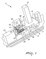
- the reference numeral 1 generally designates an electric lock with magnetic support of the coupling element.
- Each lock 1 is constituted by a fixed body 2, from which a stem 3 protrudes outward (the knob or handle for opening from the outside is connected to said stem).
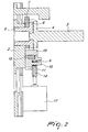
- the stem 3 has, at its base, a plate 4, which can rotate on a sleeve 5, the upper edge 6 of which rests on a contrast plate 7.
- the sleeve 5 is associated with the locking element, not shown in the figure, and therefore a rotation thereof entails a corresponding retraction (or protrusion) of said locking element; the sleeve 5 is constantly associated with the internal handle.
- the plate 4, the contrast plate 7 and the sleeve 5 have respective notches 8, which are substantially shaped in a similar manner.
- a slider 9 is located below the plate 4 and the sleeve 5, can slide on a respective linear guide, and is provided with a cylindrical pin 10 that is substantially parallel to the axis of the stem 3.
- a spring 11 is constituted by a central portion 12, which forms a cylindrical winding of metal turns, and by two linear arms 13.
- the central portion 12 is fitted on the pin 10 and covers it completely, while the two arms 13 are respectively coupled within a fixed part of the body 2 and engaged on a worm screw 14, between two successive crests 15.
- the worm screw 14 is arranged laterally with respect to the slider 9 and is parallel to the linear guide of the slider 9; a first end of the worm screw rests in a fixed seat 16 of the body 2 and a second end is rigidly coupled to the shaft of an electric motor 17.
- a magnet 18 is fixed to the upper end of the slider 9 and is designed to retain a roller 19 by magnetic attraction in close contact with the slider 9.
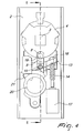
- the motor 17 is supplied with power so that it turns the worm screw 14.
- the arm 13, arranged between two successive crests 15 of the worm screw 14, is transferred from the configuration shown in Figure 3 (arm 13 proximate to the motor 17) to the configuration shown in Figure 4 (arm 13 proximate to the fixed seat 16).
- the slider 9 is subjected to a translational motion that causes its upper end (the one that accommodates the magnet 18) to face the plate 4 and the sleeve 5.
- the roller 19 (which constitutes the coupling element) is accommodated within the notches 8 of the plate 4, of the contrast plate 7 and of the sleeve 5, which are mutually superimposed.
- roller 19 in this position entails that said roller rigidly couples the plate 4, the contrast plate 7 and the sleeve 5 to each other: in this configuration ( Figure 4), a rotation of the outer knob (or handle), which induces a similar rotation of the stem 3, of the plate 4 and of the contrast plate 7, also rotates the sleeve 5, entailing the actuation of the locking element and therefore the opening of the lock 1.
- Rotation is allowed thanks to the fact that the connection between the slider 9 and the roller 19 occurs by means of the magnet 18: the rotation of the stem 3 in fact entails the rotation of the sleeve 5 (and therefore a movement of the locking element), indeed in relation to the fact that the roller 19 is free to move while keeping them mutually rigidly coupled.
- the handle is released and therefore the plate 4 and the sleeve 5 return to the initial position (in which the notches 8 face the slider 9), and the roller 19, by magnetic attraction, returns to being supported by the magnet 18 so as to adhere to the surface of the slider 9.
- Access may be possible only by having an appropriately provided key, by means of which it is possible to turn the bit 20, with a consequent action of the inclined surface 21 on the lower surface of the slider 9 that entails an upward translational motion of the slider 9 (as shown in Figure 5).
- the spring 11 undergoes a deformation, reducing the angle between its two arms 13 (because the arm 13 remains engaged in the worm screw 14 proximate to the motor 17), tending to return the slider 9 downward (return translational motion prevented by the presence of the inclined surface 21).
- the upward translational motion of the slider 9 entails the engagement of the roller 19 in the notches 8 and therefore allows actuation of the locking element by means of the knob (or handle) fitted on the stem 3.
- the slider 9 By returning the bit 20 to its initial configuration, the slider 9 again performs a downward translational motion by way of the action of the spring 11, and the rotation of the stem 3 is again independent of the rotation of the sleeve 5.
- the locking element is obviously usually the latch of the lock 1.
Landscapes
- Engineering & Computer Science (AREA)
- Structural Engineering (AREA)
- Lock And Its Accessories (AREA)
- Details Of Connecting Devices For Male And Female Coupling (AREA)
- Buckles (AREA)
- Switches That Are Operated By Magnetic Or Electric Fields (AREA)
- Magnetic Resonance Imaging Apparatus (AREA)
- Discharge Heating (AREA)
- Burglar Alarm Systems (AREA)
Claims (13)
- Serrure électrique (1) avec support magnétique de l'élément de couplage, du type comprenant un élément de verrouillage qui s'engage dans une lisière respective du chambranle, un ensemble de décodage adapté pour loger un composant qui porte un code, un premier élément d'actionnement, qui est relié à une poignée interne et qui est directement associé audit élément de verrouillage, et un second élément d'actionnement, qui est relié à une poignée externe et qui est couplé audit élément de verrouillage au moyen d'un dispositif électromécanique, caractérisée en ce que ledit second élément d'actionnement comprend, couplée de manière rigide à ladite poignée externe, une tige en saillie (3) qui se termine par une plaque rotative (4) et une plaque de contraste (7), qui peut également être mise en rotation et repose librement sur un manchon (5), qui peut également être mis en rotation mais qui est couplé de manière rigide audit élément de verrouillage, ladite plaque (4), ladite plaque de contraste (7) et ledit manchon (5) comportant des encoches respectives (8), et en ce que ledit dispositif électromécanique est constitué d'un moteur électrique (17) et d'un coulisseau (9), qui est aligné avec lesdites encoches (8) et qui peut être actionné de façon à accomplir un mouvement de translation de manière indirecte au moyen dudit moteur (17), ledit coulisseau (9) comportant un aimant (18) sur sa tête pour supporter un élément de couplage (19) qui est adapté pour faire entrer lesdites encoches (8) lorsque le coulisseau (9) est dans la position avancée, afin de coupler de manière rigide les uns aux autres ladite plaque (4), ladite plaque de contraste (7) et ledit manchon (5).
- Serrure selon la revendication 1, caractérisée en ce que le moyen de couplage (19) est un galet (19).
- Serrure selon la revendication 1, caractérisée en ce que ledit moteur (17) a une vis sans fin (14) installée sur son arbre, ledit coulisseau (9) étant associé à ladite vis sans fin (14) au moyen d'un ressort (11) avec des bras linéaires (13).
- Serrure selon une ou plusieurs des revendications précédentes, caractérisée en ce que ledit coulisseau (9) est installé de sorte qu'il puisse coulisser à l'intérieur d'un guide, et qu'il puisse accomplir un mouvement de translation depuis une première configuration, dans laquelle le galet (19) supporté par l'aimant (18) sur sa tête est complètement externe par rapport auxdites encoches (8) de la plaque (4), de la plaque de contraste (7) et du manchon (5), jusqu'à une seconde configuration, dans laquelle ledit galet (19) est logé à l'intérieur desdites encoches (8), pour coupler de manière rigide la plaque (4), la plaque de contraste (7) et le manchon (5) les uns aux autres.
- Serrure selon la revendication 4, caractérisée en ce que ladite seconde configuration dudit coulisseau (9) correspond à un agencement d'un bras (13) du ressort (11) de sorte qu'il puisse se mettre en prise sur la vis sans fin (14), ledit agencement pouvant être obtenu au moyen de la rotation de l'arbre du moteur (17), et donc de la vis sans fin (14), entre les deux crêtes d'extrémité (15) de ladite vis sans fin (14), celles qui sont les plus proches d'un siège fixe (16) qui est couplé de manière rigide au corps (2) de la serrure (1).
- Serrure selon la revendication 4, caractérisée en ce que ladite seconde configuration du type coulisseau (9) correspond à un agencement avancé du coulisseau (9) au moyen d'une action mécanique externe d'un opérateur si une puissance électrique n'est pas disponible, avec une déformation résultante du ressort (11) qui est constituée par une réduction de l'angle entre les deux bras (13).
- Serrure selon l'une ou plusieurs des revendications précédentes, caractérisée en ce qu'un bout (20) est agencé en dessous du coulisseau (9) et peut se déplacer depuis une première configuration, dans laquelle une surface inclinée (21) qui fait saillie depuis celui-ci est agencée latéralement par rapport au coulisseau (9), jusqu'à une seconde configuration, dans laquelle ledit plan incliné (21) repose sur la surface inférieure dudit coulisseau (9), après l'avoir déplacé vers le haut au moyen dudit galet (19) à l'intérieur desdites encoches (8).
- Serrure selon la revendication 7, caractérisée en ce que ledit bout (20) est mis en rotation par un opérateur au moyen d'une clé prévue de manière appropriée.
- Serrure selon l'une ou plusieurs des revendications 5 à 8, caractérisée en ce que ladite vis sans fin (14) a une extrémité qui est calée sur l'arbre de moteur(17), son extrémité opposée reposant sur ledit siège fixe (16) qui est couplé de manière rigide au corps (2) de la serrure (1).
- Serrure selon l'une ou plusieurs des revendications précédentes, caractérisée en ce que ledit ressort (11) a une extrémité (13) qui est fixée sur le corps (2) de la serrure (1), une partie centrale (12) qui est engagé sur ledit coulisseau (9), et une extrémité opposée (13) qui est logée entre deux crêtes successives (15) de ladite vis sans fin (14).
- Serrure selon la revendication 10, caractérisée en ce que ledit ressort (11) a deux longs bras linéaires (13), qui font saillie depuis ladite partie centrale (12) qui est enroulée en forme de spirale comme un cylindre creux.
- Serrure selon la revendication 11, caractérisée en ce que ledit coulisseau (9) comporte une cheville (10) qui fait saillie afin de contenir ladite partie centrale (12).
- Serrure selon l'une ou plusieurs des revendications précédentes, caractérisée en ce que l'alimentation en puissance du moteur électrique (17) est activée après insertion dudit composant qui comporte un code dans un réceptacle respectif de l'ensemble de décodage.
Applications Claiming Priority (2)
| Application Number | Priority Date | Filing Date | Title |
|---|---|---|---|
| ITBO20030583 | 2003-10-10 | ||
| ITBO20030583 ITBO20030583A1 (it) | 2003-10-10 | 2003-10-10 | Serratura elettrica a sostegno magnetico dell'organo di accoppiamento |
Publications (2)
| Publication Number | Publication Date |
|---|---|
| EP1522658A1 EP1522658A1 (fr) | 2005-04-13 |
| EP1522658B1 true EP1522658B1 (fr) | 2006-08-16 |
Family
ID=34308088
Family Applications (1)
| Application Number | Title | Priority Date | Filing Date |
|---|---|---|---|
| EP20040023759 Expired - Lifetime EP1522658B1 (fr) | 2003-10-10 | 2004-10-06 | Serrure électrique avec support magnétique de l'élément de couplage |
Country Status (7)
| Country | Link |
|---|---|
| US (1) | US7188495B2 (fr) |
| EP (1) | EP1522658B1 (fr) |
| CN (1) | CN1607307B (fr) |
| AT (1) | ATE336630T1 (fr) |
| DE (1) | DE602004001952T2 (fr) |
| ES (1) | ES2270253T3 (fr) |
| IT (1) | ITBO20030583A1 (fr) |
Cited By (2)
| Publication number | Priority date | Publication date | Assignee | Title |
|---|---|---|---|---|
| EP3741934A1 (fr) | 2019-05-22 | 2020-11-25 | Astra Gesellschaft Für Asset Management MbH&Co. Kg | Cylindre de fermeture |
| EP4575150A1 (fr) | 2023-12-22 | 2025-06-25 | Astra Gesellschaft Für Asset Management MbH&Co. Kg | Unité de fermeture électrique |
Families Citing this family (32)
| Publication number | Priority date | Publication date | Assignee | Title |
|---|---|---|---|---|
| EP1485556B1 (fr) * | 2002-03-16 | 2006-08-23 | Burg-Wächter Kg | Serrure |
| IL154193A0 (en) * | 2003-01-30 | 2003-07-31 | Goldtec Security Ltd | Door locking system |
| US7568969B2 (en) * | 2003-10-22 | 2009-08-04 | Nippei Toyama Corporation | Locking mechanism of linear motor travel slider and processing machine |
| MX2008013177A (es) * | 2006-04-13 | 2008-10-21 | Schlage Lock Co | Cerradura de perno muerto electronica. |
| FR2905401B1 (fr) * | 2006-09-04 | 2008-10-31 | Cogelec Soc Par Actions Simpli | Serrure motorisee autonome. |
| US7784315B2 (en) * | 2007-07-20 | 2010-08-31 | Ping-Jan Yang | Locking device for truck |
| TR200801927A2 (tr) * | 2008-03-24 | 2009-01-21 | Vemus Endüstri̇yel Elektroni̇k Sanayi̇ Ve Ti̇caret Li̇mi̇ted Şi̇rketi̇ | Mikro motorlu kilitleme dili sistemi. |
| US8561443B2 (en) * | 2008-11-28 | 2013-10-22 | Utc Fire & Security Corporation | Semi-active electrorheological fluid clutch for electronic door lock |
| FI20095694A7 (fi) * | 2009-01-05 | 2010-07-06 | Megalock Oy | Langattomasti ohjattava sähkölukko |
| DE102009006352B4 (de) * | 2009-01-28 | 2011-02-17 | G. Schwepper Beschlag Gmbh + Co | Lock-Box |
| CN102007257B (zh) * | 2009-02-05 | 2013-09-04 | 阿海珐输配电意大利股份公司 | 用于手动操作锁定/释放驱动轴尤其是电气断路器的机构的机电装置 |
| CH701790A2 (de) * | 2009-08-31 | 2011-03-15 | Kaba Ag | Schliesseinrichtung. |
| US8555685B2 (en) * | 2009-10-05 | 2013-10-15 | George Frolov | Electrically controlled door lock |
| CN102199957B (zh) * | 2010-03-23 | 2013-06-05 | 鸿富锦精密工业(深圳)有限公司 | 磁锁装置 |
| US8590948B2 (en) * | 2011-01-12 | 2013-11-26 | I-Tek Metal Mfg. Co., Ltd | Outer operational device for panic exit door lock |
| NZ616556A (en) * | 2011-03-11 | 2015-07-31 | Schlage Lock Co Llc | Multi-mode lock assembly |
| WO2012177609A1 (fr) * | 2011-06-20 | 2012-12-27 | Newfrey Llc | Ensemble pêne dormant électronique entraîné manuellement comportant un biseau à montage libre |
| US9051761B2 (en) | 2011-08-02 | 2015-06-09 | Kwikset Corporation | Manually driven electronic deadbolt assembly with fixed turnpiece |
| US8904836B2 (en) * | 2012-07-18 | 2014-12-09 | Scyan Electronics LLC | Handle fixing mechanisms and methods of making and using thereof |
| WO2014151024A1 (fr) | 2013-03-15 | 2014-09-25 | Kwikset Corporation | Serrures électromécaniques dotées d'une fonction de rotation de lunette |
| DE102014104607B3 (de) * | 2014-04-01 | 2015-09-17 | Dom Sicherheitstechnik Gmbh & Co Kg | Elektromechanische Kupplungsanordnung mit magnetischem Drehschalter und Verfahren |
| US20160097220A1 (en) * | 2014-10-01 | 2016-04-07 | Yiqi Wu Woodling | Cabinet Locking Device Using an Electromagnetic Switch Actuated System with Fingerprint Identification, Combination Code and Bluetooth System |
| JP2016108928A (ja) * | 2014-12-02 | 2016-06-20 | Ntn株式会社 | 電気錠 |
| US10260253B2 (en) * | 2015-04-09 | 2019-04-16 | Townsteel, Inc. | Door trim assembly with clutch mechanism |
| FI126771B (fi) * | 2015-04-21 | 2017-05-15 | Abloy Oy | Lukkorunko |
| WO2016173716A2 (fr) * | 2015-04-29 | 2016-11-03 | Alexandra Baum | Antivol à câble pour la sécurisation d'objets |
| US10407942B2 (en) * | 2015-08-13 | 2019-09-10 | Spectrum Brands, Inc. | Low profile deadbolt |
| CH712730A1 (de) * | 2016-07-21 | 2018-01-31 | Kaba Ag | Kopplungsmechanismus mit einem zwangsgeführten Kopplungselement für ein mechatronisches Schliesssystem. |
| CN107620527B (zh) * | 2017-08-22 | 2019-03-05 | 梁文逊 | 自适应电动双控智能锁 |
| WO2020055851A1 (fr) | 2018-09-10 | 2020-03-19 | Spectrum Brands, Inc. | Ensemble de verrouillage avec mécanisme à ressort |
| US10961746B2 (en) * | 2018-09-20 | 2021-03-30 | Dormakaba Usa Inc. | Mortise lock and mortise lock systems and methods |
| CN112523615A (zh) * | 2020-11-18 | 2021-03-19 | 嘉兴美可泰科技有限公司 | 一种机电变频电磁阀锁的操作方法及机电变频电磁阀锁 |
Family Cites Families (15)
| Publication number | Priority date | Publication date | Assignee | Title |
|---|---|---|---|---|
| US4820330A (en) * | 1987-07-30 | 1989-04-11 | Jeun-Kuen Lee | Structure for controlling the dead bolt used in an electronic lock |
| CN2031820U (zh) * | 1988-08-14 | 1989-02-01 | 何益波 | 节电密码电脑锁 |
| US5027629A (en) * | 1990-01-22 | 1991-07-02 | Liu Yin Chic | Control mechanism of electronic lock |
| SE9000525D0 (sv) * | 1990-02-14 | 1990-02-14 | Leif Nordqvist | Kopplingsmekanism |
| ATA96090A (de) * | 1990-04-25 | 1991-12-15 | Skidata Gmbh | Tuerschloss mit einer von einer seite mittels eines schluessels oeffenbaren falle |
| US5475996A (en) * | 1994-08-29 | 1995-12-19 | Chen; Tsun-Hsing | Electromagnetic door lock |
| US5862903A (en) * | 1994-12-02 | 1999-01-26 | Itt Automotive Electrical Systems, Inc. | Centrifugal clutch for power door locks |
| WO2000068534A2 (fr) * | 1999-05-06 | 2000-11-16 | Ilco Unican Inc. | Verrou electromecanique |
| DE19960791C1 (de) * | 1999-12-16 | 2001-04-05 | Sphinx Elektronik Gmbh | Schloss mit einer elektromechanischen Kupplungsvorrichtung |
| ES2193793B2 (es) * | 2000-03-01 | 2005-02-01 | Escudos Kala Internacional, S.L. | Mecanismo de condena para cerraduras electronicas. |
| US6666053B2 (en) * | 2001-12-19 | 2003-12-23 | Randall C. Hansen | Reversible spring-loaded lock slide |
| CN2520432Y (zh) * | 2002-02-05 | 2002-11-13 | 烟台鸿桥高科技有限公司 | 一种圆柱凸轮离合控制装置 |
| GB2390394B (en) * | 2002-07-03 | 2004-05-26 | Shyang Feng Electric & Machine | Improved electronic lock |
| US6851291B2 (en) * | 2002-11-26 | 2005-02-08 | Sargent Manufacturing | Motorized locking mechanism |
| IL154193A0 (en) * | 2003-01-30 | 2003-07-31 | Goldtec Security Ltd | Door locking system |
-
2003
- 2003-10-10 IT ITBO20030583 patent/ITBO20030583A1/it unknown
-
2004
- 2004-10-06 EP EP20040023759 patent/EP1522658B1/fr not_active Expired - Lifetime
- 2004-10-06 ES ES04023759T patent/ES2270253T3/es not_active Expired - Lifetime
- 2004-10-06 AT AT04023759T patent/ATE336630T1/de active
- 2004-10-06 DE DE602004001952T patent/DE602004001952T2/de not_active Expired - Lifetime
- 2004-10-07 US US10/959,090 patent/US7188495B2/en not_active Expired - Fee Related
- 2004-10-10 CN CN2004100855345A patent/CN1607307B/zh not_active Expired - Fee Related
Cited By (5)
| Publication number | Priority date | Publication date | Assignee | Title |
|---|---|---|---|---|
| EP3741934A1 (fr) | 2019-05-22 | 2020-11-25 | Astra Gesellschaft Für Asset Management MbH&Co. Kg | Cylindre de fermeture |
| DE102019113666A1 (de) * | 2019-05-22 | 2020-11-26 | ASTRA Gesellschaft für Asset Management mbH & Co. KG | Schließzylinder |
| DE102019113666B4 (de) | 2019-05-22 | 2022-09-29 | ASTRA Gesellschaft für Asset Management mbH & Co. KG | Elektrischer Schließzylinder für ein Schloss |
| EP4575150A1 (fr) | 2023-12-22 | 2025-06-25 | Astra Gesellschaft Für Asset Management MbH&Co. Kg | Unité de fermeture électrique |
| DE102023136459A1 (de) * | 2023-12-22 | 2025-06-26 | ASTRA Gesellschaft für Asset Management mbH & Co. KG | Elektrische Schließeinheit |
Also Published As
| Publication number | Publication date |
|---|---|
| CN1607307A (zh) | 2005-04-20 |
| US20050092046A1 (en) | 2005-05-05 |
| EP1522658A1 (fr) | 2005-04-13 |
| CN1607307B (zh) | 2011-05-18 |
| DE602004001952T2 (de) | 2007-01-18 |
| ES2270253T3 (es) | 2007-04-01 |
| ATE336630T1 (de) | 2006-09-15 |
| DE602004001952D1 (de) | 2006-09-28 |
| ITBO20030583A1 (it) | 2005-04-11 |
| US7188495B2 (en) | 2007-03-13 |
Similar Documents
| Publication | Publication Date | Title |
|---|---|---|
| EP1522658B1 (fr) | Serrure électrique avec support magnétique de l'élément de couplage | |
| EP1522659B1 (fr) | Serrure électrique avec un ressort multifonctions | |
| US7874190B2 (en) | Electromechanical lock cylinder | |
| CN100417784C (zh) | 磁机械式闭锁装置 | |
| US5421178A (en) | Motorized lock actuator for cylindrical lockset | |
| EP3165694B1 (fr) | Verrou à came électronique miniaturisé | |
| US20200263451A1 (en) | Inline motorized lock drive for solenoid replacement | |
| US5953942A (en) | Catch mechanism for locks | |
| KR100627538B1 (ko) | 전기제어식 잠금장치 | |
| US4736970A (en) | Electrically controlled door lock | |
| RU2337220C2 (ru) | Цилиндровый дверной замок | |
| ES2926957T3 (es) | Elemento de accionamiento para una cerradura de caja | |
| JPH0227506B2 (fr) | ||
| WO1998015703A1 (fr) | Serrure electromecanique | |
| PL190093B1 (pl) | Urządzenie zamykające | |
| US5865483A (en) | Electromechanical locking system | |
| US20240191546A1 (en) | Door-strike | |
| JPH02157376A (ja) | 錠 | |
| CN107923196A (zh) | 具有监测保持器的电锁口系统 | |
| US10829958B2 (en) | Handle assembly with lock, particularly for a glass leaf | |
| EP1526235B1 (fr) | Serrure avec tige de poignée verrouillable | |
| CZ119797A3 (en) | Yale-lock tumbler-pin | |
| JP2004332252A (ja) | 施錠装置 | |
| EP1526234A1 (fr) | Serrure avec tige de poignée verrouillable |
Legal Events
| Date | Code | Title | Description |
|---|---|---|---|
| PUAI | Public reference made under article 153(3) epc to a published international application that has entered the european phase |
Free format text: ORIGINAL CODE: 0009012 |
|
| AK | Designated contracting states |
Kind code of ref document: A1 Designated state(s): AT BE BG CH CY CZ DE DK EE ES FI FR GB GR HU IE IT LI LU MC NL PL PT RO SE SI SK TR |
|
| AX | Request for extension of the european patent |
Extension state: AL HR LT LV MK |
|
| 17P | Request for examination filed |
Effective date: 20050906 |
|
| RAP1 | Party data changed (applicant data changed or rights of an application transferred) |
Owner name: CISA S.P.A. |
|
| AKX | Designation fees paid |
Designated state(s): AT BE BG CH CY CZ DE DK EE ES FI FR GB GR HU IE IT LI LU MC NL PL PT RO SE SI SK TR |
|
| GRAP | Despatch of communication of intention to grant a patent |
Free format text: ORIGINAL CODE: EPIDOSNIGR1 |
|
| GRAS | Grant fee paid |
Free format text: ORIGINAL CODE: EPIDOSNIGR3 |
|
| GRAA | (expected) grant |
Free format text: ORIGINAL CODE: 0009210 |
|
| AK | Designated contracting states |
Kind code of ref document: B1 Designated state(s): AT BE BG CH CY CZ DE DK EE ES FI FR GB GR HU IE IT LI LU MC NL PL PT RO SE SI SK TR |
|
| PG25 | Lapsed in a contracting state [announced via postgrant information from national office to epo] |
Ref country code: SI Free format text: LAPSE BECAUSE OF FAILURE TO SUBMIT A TRANSLATION OF THE DESCRIPTION OR TO PAY THE FEE WITHIN THE PRESCRIBED TIME-LIMIT Effective date: 20060816 Ref country code: PL Free format text: LAPSE BECAUSE OF FAILURE TO SUBMIT A TRANSLATION OF THE DESCRIPTION OR TO PAY THE FEE WITHIN THE PRESCRIBED TIME-LIMIT Effective date: 20060816 Ref country code: RO Free format text: LAPSE BECAUSE OF FAILURE TO SUBMIT A TRANSLATION OF THE DESCRIPTION OR TO PAY THE FEE WITHIN THE PRESCRIBED TIME-LIMIT Effective date: 20060816 Ref country code: FI Free format text: LAPSE BECAUSE OF FAILURE TO SUBMIT A TRANSLATION OF THE DESCRIPTION OR TO PAY THE FEE WITHIN THE PRESCRIBED TIME-LIMIT Effective date: 20060816 Ref country code: IT Free format text: LAPSE BECAUSE OF FAILURE TO SUBMIT A TRANSLATION OF THE DESCRIPTION OR TO PAY THE FEE WITHIN THE PRESCRIBED TIME-LIMIT;WARNING: LAPSES OF ITALIAN PATENTS WITH EFFECTIVE DATE BEFORE 2007 MAY HAVE OCCURRED AT ANY TIME BEFORE 2007. THE CORRECT EFFECTIVE DATE MAY BE DIFFERENT FROM THE ONE RECORDED. Effective date: 20060816 |
|
| REG | Reference to a national code |
Ref country code: GB Ref legal event code: FG4D |
|
| REG | Reference to a national code |
Ref country code: CH Ref legal event code: EP |
|
| REG | Reference to a national code |
Ref country code: IE Ref legal event code: FG4D |
|
| REF | Corresponds to: |
Ref document number: 602004001952 Country of ref document: DE Date of ref document: 20060928 Kind code of ref document: P |
|
| REG | Reference to a national code |
Ref country code: CH Ref legal event code: NV Representative=s name: ROTTMANN, ZIMMERMANN + PARTNER AG |
|
| PG25 | Lapsed in a contracting state [announced via postgrant information from national office to epo] |
Ref country code: IE Free format text: LAPSE BECAUSE OF NON-PAYMENT OF DUE FEES Effective date: 20061006 |
|
| PG25 | Lapsed in a contracting state [announced via postgrant information from national office to epo] |
Ref country code: MC Free format text: LAPSE BECAUSE OF NON-PAYMENT OF DUE FEES Effective date: 20061031 |
|
| REG | Reference to a national code |
Ref country code: GR Ref legal event code: EP Ref document number: 20060403371 Country of ref document: GR |
|
| PG25 | Lapsed in a contracting state [announced via postgrant information from national office to epo] |
Ref country code: SE Free format text: LAPSE BECAUSE OF FAILURE TO SUBMIT A TRANSLATION OF THE DESCRIPTION OR TO PAY THE FEE WITHIN THE PRESCRIBED TIME-LIMIT Effective date: 20061116 Ref country code: DK Free format text: LAPSE BECAUSE OF FAILURE TO SUBMIT A TRANSLATION OF THE DESCRIPTION OR TO PAY THE FEE WITHIN THE PRESCRIBED TIME-LIMIT Effective date: 20061116 |
|
| PG25 | Lapsed in a contracting state [announced via postgrant information from national office to epo] |
Ref country code: PT Free format text: LAPSE BECAUSE OF FAILURE TO SUBMIT A TRANSLATION OF THE DESCRIPTION OR TO PAY THE FEE WITHIN THE PRESCRIBED TIME-LIMIT Effective date: 20070116 |
|
| ET | Fr: translation filed | ||
| REG | Reference to a national code |
Ref country code: ES Ref legal event code: FG2A Ref document number: 2270253 Country of ref document: ES Kind code of ref document: T3 |
|
| PLBE | No opposition filed within time limit |
Free format text: ORIGINAL CODE: 0009261 |
|
| STAA | Information on the status of an ep patent application or granted ep patent |
Free format text: STATUS: NO OPPOSITION FILED WITHIN TIME LIMIT |
|
| 26N | No opposition filed |
Effective date: 20070518 |
|
| PG25 | Lapsed in a contracting state [announced via postgrant information from national office to epo] |
Ref country code: EE Free format text: LAPSE BECAUSE OF FAILURE TO SUBMIT A TRANSLATION OF THE DESCRIPTION OR TO PAY THE FEE WITHIN THE PRESCRIBED TIME-LIMIT Effective date: 20060816 |
|
| PG25 | Lapsed in a contracting state [announced via postgrant information from national office to epo] |
Ref country code: HU Free format text: LAPSE BECAUSE OF FAILURE TO SUBMIT A TRANSLATION OF THE DESCRIPTION OR TO PAY THE FEE WITHIN THE PRESCRIBED TIME-LIMIT Effective date: 20070217 |
|
| PG25 | Lapsed in a contracting state [announced via postgrant information from national office to epo] |
Ref country code: CY Free format text: LAPSE BECAUSE OF FAILURE TO SUBMIT A TRANSLATION OF THE DESCRIPTION OR TO PAY THE FEE WITHIN THE PRESCRIBED TIME-LIMIT Effective date: 20060816 |
|
| PGFP | Annual fee paid to national office [announced via postgrant information from national office to epo] |
Ref country code: SK Payment date: 20100930 Year of fee payment: 7 |
|
| PGFP | Annual fee paid to national office [announced via postgrant information from national office to epo] |
Ref country code: NL Payment date: 20101028 Year of fee payment: 7 |
|
| PGFP | Annual fee paid to national office [announced via postgrant information from national office to epo] |
Ref country code: BG Payment date: 20101020 Year of fee payment: 7 Ref country code: CH Payment date: 20101101 Year of fee payment: 7 Ref country code: CZ Payment date: 20101004 Year of fee payment: 7 Ref country code: LU Payment date: 20101014 Year of fee payment: 7 |
|
| PGFP | Annual fee paid to national office [announced via postgrant information from national office to epo] |
Ref country code: TR Payment date: 20101001 Year of fee payment: 7 |
|
| REG | Reference to a national code |
Ref country code: CH Ref legal event code: PFA Owner name: CISA S.P.A. Free format text: CISA S.P.A.#VIA OBERDAN 42#48018 FAENZA RA (IT) -TRANSFER TO- CISA S.P.A.#VIA OBERDAN 42#48018 FAENZA RA (IT) |
|
| PG25 | Lapsed in a contracting state [announced via postgrant information from national office to epo] |
Ref country code: CZ Free format text: LAPSE BECAUSE OF NON-PAYMENT OF DUE FEES Effective date: 20111006 |
|
| REG | Reference to a national code |
Ref country code: NL Ref legal event code: V1 Effective date: 20120501 |
|
| REG | Reference to a national code |
Ref country code: CH Ref legal event code: PL |
|
| REG | Reference to a national code |
Ref country code: SK Ref legal event code: MM4A Ref document number: E 1008 Country of ref document: SK Effective date: 20111006 |
|
| PG25 | Lapsed in a contracting state [announced via postgrant information from national office to epo] |
Ref country code: LI Free format text: LAPSE BECAUSE OF NON-PAYMENT OF DUE FEES Effective date: 20111031 Ref country code: NL Free format text: LAPSE BECAUSE OF NON-PAYMENT OF DUE FEES Effective date: 20120501 Ref country code: SK Free format text: LAPSE BECAUSE OF NON-PAYMENT OF DUE FEES Effective date: 20111006 Ref country code: CH Free format text: LAPSE BECAUSE OF NON-PAYMENT OF DUE FEES Effective date: 20111031 |
|
| PGFP | Annual fee paid to national office [announced via postgrant information from national office to epo] |
Ref country code: GR Payment date: 20120926 Year of fee payment: 9 |
|
| PGFP | Annual fee paid to national office [announced via postgrant information from national office to epo] |
Ref country code: AT Payment date: 20120926 Year of fee payment: 9 |
|
| PG25 | Lapsed in a contracting state [announced via postgrant information from national office to epo] |
Ref country code: LU Free format text: LAPSE BECAUSE OF NON-PAYMENT OF DUE FEES Effective date: 20111006 |
|
| PG25 | Lapsed in a contracting state [announced via postgrant information from national office to epo] |
Ref country code: BG Free format text: LAPSE BECAUSE OF NON-PAYMENT OF DUE FEES Effective date: 20120630 |
|
| PG25 | Lapsed in a contracting state [announced via postgrant information from national office to epo] |
Ref country code: TR Free format text: LAPSE BECAUSE OF NON-PAYMENT OF DUE FEES Effective date: 20111006 |
|
| PGFP | Annual fee paid to national office [announced via postgrant information from national office to epo] |
Ref country code: GB Payment date: 20130930 Year of fee payment: 10 |
|
| PGFP | Annual fee paid to national office [announced via postgrant information from national office to epo] |
Ref country code: BE Payment date: 20131030 Year of fee payment: 10 |
|
| REG | Reference to a national code |
Ref country code: AT Ref legal event code: MM01 Ref document number: 336630 Country of ref document: AT Kind code of ref document: T Effective date: 20131006 |
|
| REG | Reference to a national code |
Ref country code: GR Ref legal event code: ML Ref document number: 20060403371 Country of ref document: GR Effective date: 20140505 |
|
| PG25 | Lapsed in a contracting state [announced via postgrant information from national office to epo] |
Ref country code: AT Free format text: LAPSE BECAUSE OF NON-PAYMENT OF DUE FEES Effective date: 20131006 Ref country code: GR Free format text: LAPSE BECAUSE OF NON-PAYMENT OF DUE FEES Effective date: 20140505 |
|
| REG | Reference to a national code |
Ref country code: DE Ref legal event code: R082 Ref document number: 602004001952 Country of ref document: DE Representative=s name: SCHAUMBURG & PARTNER PATENTANWAELTE GBR, DE Ref country code: DE Ref legal event code: R082 Ref document number: 602004001952 Country of ref document: DE Representative=s name: SCHAUMBURG & PARTNER PATENTANWAELTE MBB, DE Ref country code: DE Ref legal event code: R082 Ref document number: 602004001952 Country of ref document: DE Representative=s name: SCHAUMBURG UND PARTNER PATENTANWAELTE MBB, DE |
|
| GBPC | Gb: european patent ceased through non-payment of renewal fee |
Effective date: 20141006 |
|
| PG25 | Lapsed in a contracting state [announced via postgrant information from national office to epo] |
Ref country code: BE Free format text: LAPSE BECAUSE OF NON-PAYMENT OF DUE FEES Effective date: 20141031 |
|
| PG25 | Lapsed in a contracting state [announced via postgrant information from national office to epo] |
Ref country code: GB Free format text: LAPSE BECAUSE OF NON-PAYMENT OF DUE FEES Effective date: 20141006 |
|
| REG | Reference to a national code |
Ref country code: FR Ref legal event code: PLFP Year of fee payment: 12 |
|
| PGFP | Annual fee paid to national office [announced via postgrant information from national office to epo] |
Ref country code: IT Payment date: 20151023 Year of fee payment: 12 Ref country code: DE Payment date: 20151028 Year of fee payment: 12 |
|
| PGFP | Annual fee paid to national office [announced via postgrant information from national office to epo] |
Ref country code: ES Payment date: 20151028 Year of fee payment: 12 Ref country code: FR Payment date: 20151028 Year of fee payment: 12 |
|
| REG | Reference to a national code |
Ref country code: DE Ref legal event code: R119 Ref document number: 602004001952 Country of ref document: DE |
|
| REG | Reference to a national code |
Ref country code: FR Ref legal event code: ST Effective date: 20170630 |
|
| PG25 | Lapsed in a contracting state [announced via postgrant information from national office to epo] |
Ref country code: FR Free format text: LAPSE BECAUSE OF NON-PAYMENT OF DUE FEES Effective date: 20161102 Ref country code: DE Free format text: LAPSE BECAUSE OF NON-PAYMENT OF DUE FEES Effective date: 20170503 |
|
| PG25 | Lapsed in a contracting state [announced via postgrant information from national office to epo] |
Ref country code: IT Free format text: LAPSE BECAUSE OF NON-PAYMENT OF DUE FEES Effective date: 20161006 |
|
| PG25 | Lapsed in a contracting state [announced via postgrant information from national office to epo] |
Ref country code: ES Free format text: LAPSE BECAUSE OF NON-PAYMENT OF DUE FEES Effective date: 20161007 |
|
| REG | Reference to a national code |
Ref country code: ES Ref legal event code: FD2A Effective date: 20181126 |