EP1522657B1 - Poignée de porte d'un véhicule automobile avec un dispositif de montage - Google Patents
Poignée de porte d'un véhicule automobile avec un dispositif de montage Download PDFInfo
- Publication number
- EP1522657B1 EP1522657B1 EP20040023843 EP04023843A EP1522657B1 EP 1522657 B1 EP1522657 B1 EP 1522657B1 EP 20040023843 EP20040023843 EP 20040023843 EP 04023843 A EP04023843 A EP 04023843A EP 1522657 B1 EP1522657 B1 EP 1522657B1
- Authority
- EP
- European Patent Office
- Prior art keywords
- handle
- back plate
- mounting device
- recess
- door
- Prior art date
- Legal status (The legal status is an assumption and is not a legal conclusion. Google has not performed a legal analysis and makes no representation as to the accuracy of the status listed.)
- Expired - Lifetime
Links
- 238000006073 displacement reaction Methods 0.000 claims description 6
- 230000004913 activation Effects 0.000 claims 1
- 230000033001 locomotion Effects 0.000 description 4
- 230000007246 mechanism Effects 0.000 description 4
- 230000003213 activating effect Effects 0.000 description 2
- 238000011161 development Methods 0.000 description 2
- 230000018109 developmental process Effects 0.000 description 2
- 238000009434 installation Methods 0.000 description 2
- 238000000034 method Methods 0.000 description 2
- 238000004873 anchoring Methods 0.000 description 1
- 238000013459 approach Methods 0.000 description 1
- 238000000429 assembly Methods 0.000 description 1
- 230000005540 biological transmission Effects 0.000 description 1
- 230000015572 biosynthetic process Effects 0.000 description 1
- 230000000903 blocking effect Effects 0.000 description 1
- 239000002131 composite material Substances 0.000 description 1
- 230000001419 dependent effect Effects 0.000 description 1
- 238000005755 formation reaction Methods 0.000 description 1
- 238000003780 insertion Methods 0.000 description 1
- 230000037431 insertion Effects 0.000 description 1
- 230000003993 interaction Effects 0.000 description 1
- 238000004519 manufacturing process Methods 0.000 description 1
Images



Classifications
-
- E—FIXED CONSTRUCTIONS
- E05—LOCKS; KEYS; WINDOW OR DOOR FITTINGS; SAFES
- E05B—LOCKS; ACCESSORIES THEREFOR; HANDCUFFS
- E05B79/00—Mounting or connecting vehicle locks or parts thereof
- E05B79/02—Mounting of vehicle locks or parts thereof
- E05B79/06—Mounting of handles, e.g. to the wing or to the lock
Definitions
- the invention relates to a door handle assembly with a handle plate, a handle shell and a handle with a Montagearret ist for a motor vehicle door.
- preformed and pre-assembled parts are used. It depends on the automotive industry that these pre-assembled parts can be assembled quickly and without many or complicated steps.
- Customary is the installation of door handles in an opening in the door panel of a motor vehicle door from the inside and from the outside, wherein an externally patched handle shell screwed with internally mounted components, locked or connected by complex mechanisms.
- the invention is therefore based on the object to provide a solution for preassembled parts of a door handle assembly of a motor vehicle, in which the final assembly is simplified.
- An advantageous embodiment of the invention proposes that at the Montagearret ist one or more locking devices is provided which cooperate with extensions, in particular with a cross-sectionally T-shaped pin on the handle shell, which extensions in the mounting position of handle plate and handle shell by extension openings protrude the handle plate, wherein after moving the Montagearret réelle from the mounting position into the locking position, a positive and / or non-positive connection of handle shell and handle plate and / or handle by means of the locking device and the extensions.
- the Montagearret ist is designed so that the determination of the handle shell and / or the handle takes place together with the handle plate by means of a mechanical bias to each other, the locking means for this purpose have resiliently biased attachment projections
- the actuating lever is provided for cooperation with a boom of the handle and in particular mechanically biased against the boom.
- the actuating lever on a sliding surface which is deflected at a deflection of the handle about the bearing axis by means of the boom, the actuating lever against the mechanical bias of the actuating lever to the abutment axis and so transmits a mechanical work on a Bowden cable.
- a preferred embodiment of the invention provides that the boom protrudes through an opening in the handle plate so as to be able to interact with the control lever mounted on the handle plate.
- a no less advantageous development of the invention provides that the defined position in which the actuating lever is held in the mounting position of the mounting catch on the handle plate is selected so that the actuating lever is deflected against its mechanical bias of the boom opening.
- a preferred embodiment of the invention provides that the actuating lever is rotatably mounted on the handle plate on an abutment axis and the locking device of Montagearretsammlung blocked in the mounting position by means of cooperating with the locking device counter locking on the actuating lever the actuating lever, the Montagearret réelle relative to the operating lever in particular linearly displaceable is stored.
- a particularly preferred embodiment of the invention provides that at the Montagearret réelle a Verrastungsfortsatz is provided which engages behind the latching position of the mounting position in the locking position on an edge or a projection of the handle plate or the handle shell and locked, thereby moving back the Montagearret réelle is prevented.
- An alternative embodiment of the invention provides that the Montagearretsammlung has a cam, which is engaged behind in the mounting position by a pivotally mounted on the handle plate locking lever so as to prevent accidental displacement of Montagearret réelle in the locking position.
- the cam of the locking lever is not engaged behind and the Montagearret réelle can be spent in the locking position.
- Fig. 1 shows a mounting bracket 1 for a determination of a handle plate with a handle with hinged thereto handle.
- the Montagearretmaschine has an actuating extension 13, in the form of a hook, by means of which the Montagearretmaschine can be activated.
- Verrastungsfortians 14 are provided on the Montagearrettechnik, which engages behind the lock plate and after locking the mounting arrest in a locking position of the handle plate.
- the right-hand latching process in the image is bent into the image plane, while the left-hand latching process in the image is bent out of the image plane.
- a locking device 11 is integrally formed on the mounting catch 1, which cooperates with a locking counterpart (51) on the actuating lever (5), wherein the locking device 11 is bent in an L-shape facing the viewer out of the image plane.
- the determination of the handle plate and the handle shell is effected by the integrally formed on the Montagearretmaschine two locking devices 12, which cooperate with T-shaped pin on the handle shell. Since the Montagearret réelle is mounted on the handle plate, the handle shell and the handle plate is so securely connected.
- the locking device has in each case two fixing extensions 121.
- Fig. 2 shows the mounting stop 1 Fig. 1 when installed in a preassembled handle plate 2.
- the Montageearret ist 1 is guided on the handle plate 2 in guides 21, which allow a linear movement corresponding to the image plane down.
- the rotatably mounted about the abutment axis 53 actuating lever 5 is biased against a spring tension, counterclockwise, and held in this position by the locking device 11, which forms a positive connection with two formations from the operating lever 5 as locking counterparts 51.
- the operating lever 5 directs a deflection about its abutment axis 53, which it experiences by a protruding through the boom opening 23 after final assembly boom (41) on a Bowden cable 7, which emits the force to a door lock mechanism, not shown.
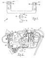
- FIG. 3 shows a door handle assembly 6 from above in a plan view.
- the grip 3, with it on a bearing axis 42 mounted handle 4 is through the Montagearret ist (not shown in this illustration) connected to the handle plate 2.
- Fig. 4 shows the assembled door handle assembly 6 from the side in another plan view.
- FIGS. 5 and 6 The assembly of handle plate and handle shell, with unlocking the mounted on the handle plate operating lever is in the FIGS. 5 and 6 shown in more detail.
- Fig. 5 shows again the preassembled handle plate Fig. 2 ,
- the Montageearret ist 1 is in the mounting position M, the actuating lever 5 is blocked by the locking device 11, and the locking counterparts 51 in the counter-clockwise biased position, so that the boom opening 23 is largely openly accessible.
- the extension openings 22 are also in the mounting position M of Montagearrettechnik 1 open, so that there later the extensions 31 of the handle shell 3 can be inserted through and fixed (see later Fig. 6 ).
- the latching extensions 14 are not yet locked behind a projection.
- Fig. 6 shows the state after assembly with a handle shell 3 after the Montagearretmaschine 1 has been pulled from the mounting position M in the locking position A.
- the locking device 3 is concealed by the handle plate 2.
- the locking means 12 of the Montagearret réelle 1 locks the extensions 31 of the handle shell, which are formed by cross-sectionally T-shaped pin 32 and project through the extension openings.
- the extensions 31 are fixed in the locking position A of the mounting catch 1 by the fixing projections 121 of the two locking devices 12.
- the fixing projections 121 are bent out of the plane of Montageearrettechnik, creating a reliable and play-free connection of handle shell and handle plate by their elastic property.
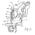
- this is equipped with a locking lever 15 which can secure the mounting catch 1 in the mounting position against unwanted displacement in the direction of locking position A before assembly with the handle shell.
- the arranged in the region of an extension opening locking lever 15 is mounted horizontally to the edge 24 of the handle plate 2 pivotally mounted on an axis 16 and spring-loaded via a leg spring 17 in a clockwise direction.
- the lock lever 15 at its one end via a projection 151 which engages behind a cam 18 of the Montagearretsammlung 1 positively, so that the Montagearret réelle 1 can be prevented from displacement into the locking position.
- a stop surface 152 is integrally formed on the locking lever 15 in the region of the extension opening, which occurs during assembly of the handle plate 2 and handle shell with an extension of the handle in interaction.
- the locking lever 15 has been displaced so far in the course of this assembly by inserting the extension 31 in the extension opening via its stop surface 152 counterclockwise that the projection 151 of the locking lever 15, the cam 18 no longer engages behind. In this position, the locking lever 15, the Montageearret ist 1 could be pulled freely from the mounting position in the locking position A.
- Fig. 8 to Fig. 13 show in individual steps in schematic cross-sectional representations of an assembly of a handle with handle mounted thereon on a handle shell to illustrate once again the operation of the installation.
- Fig. 8 shows the mounted on the inside 61a of the door panel 61 of the vehicle door 62 handle plate 2.
- the mounting catch 1 is in the mounting position, the operating lever 5 is therefore locked so that the boom opening 23 is free.
- FIG. 9 to FIG. 12 the introduction of the handle 3 in the handle plate 2 and thus the boom 41 in the boom opening 23 is shown. Since the handle shell 3 with the handle 4 is a preassembled part, the pivoting of the later occupied by the operating lever 5 space (see Fig. 13 ) needed to use the handle shell with handle can.
- Fig. 13 shows the mounted state of the door handle assembly 6 together with a fixed grip 2 and handle plate 3 and released and therefore on the boom 41 fitting actuating lever 5.
- the Montagearret ist is in the locking position A.
Landscapes
- Lock And Its Accessories (AREA)
Claims (13)
- Agencement de poignée de portière (6) avec une plaque de poignée (2), une coque de poignée (3) et une prise (4) avec un blocage de montage (1) pour une portière de véhicule, grâce au blocage de montage (1), une prise (4) à utiliser à l'extérieur à l'agencement de poignée de portière (6) et coopérant avec un levier d'actionnement (5) et une coque de poignée (3) maintenant en particulier la prise (4) se trouvant à la plaque de poignée (2) pouvant être fixée dans une position bloquant ensemble la plaque de poignée (2) et la coque de poignée (3) et le cas échéant la prise (4) ; le blocage de montage (1) pour fixer la coque de poignée (3) et le cas échéant la prise (4) et pouvant être déplacée d'une position de montage (M) en une position de blocage (A) en une association mécanique et/ou par ressort de la coque de poignée (3), de la plaque de poignée (2) et le cas échéant de la prise (4), le blocage de montage (1) comprenant un dispositif de blocage coopérant avec la contre-pièce de blocage (51) au levier d'actionnement (5) de façon que le levier d'actionnement (5) se trouvant en position de montage (M) du blocage de montage (1) à la plaque de poignée (2) soit maintenu dans une position définie.
- Agencement de poignée de portière (6) avec une plaque de poignée (2), une coque de poignée (3) et une prise (4) avec un blocage de montage (1) selon la revendication 1 caractérisé en ce
qu'au blocage de montage (1), un ou plusieurs dispositifs de blocages (12) sont prévus qui coopèrent avec la coque de poignée (3) avec les prolongements (31), en particulier avec les tenons (32) à section en forme de T, qui sortent les prolongements (31), en position de montage de la plaque de poignée et la coque de poignée, par les ouvertures de prolongement (22) de la plaque de poignée (2), après le passage du blocage de montage (1) de la position de montage (M) à la position de blocage (A), une association mécanique et/ou par ressort de la coque de poignée (3), de la plaque de poignée (2) et de la prise (4) s'effectuent à l'aide du dispositif de blocage (12) et des prolongements (31). - Agencement de poignée de portière (6) avec une plaque de poignée (2), une coque de poignée (3) et une prise (4) avec un blocage de montage (1) selon la revendication 1 ou 2 caractérisé en ce
que le blocage de montage (1) est exécuté de façon que la fixation de la coque de poignée (3) et de la prise (4) avec la plaque de poignée (2) s'effectue l'un sur l'autre à l'aide d'une prétension mécanique, les dispositifs de blocage (12) présentant à cet effet des prolongements de fixation (121) prétendus par ressort. - Agencement de poignée de portière (6) avec une plaque de poignée (2), une coque de poignée (3) et une prise (4) avec un blocage de montage (1) selon la revendication 1 à 3 caractérisé en ce
que la plaque de poignée (2) par la partie intérieure (61a) de la tôle de portière (61) de la portière de véhicule (62) et la coque de poignée (3) par la partie extérieure (61b) de la tôle de portière (61) de la portière de véhicule (62) posent sur une zone périphérique (63) d'une ouverture dans la tôle (61) en position bloquée ou lors du montage. - Agencement de poignée de portière (6) avec une plaque de poignée (2), une coque de poignée (3) et une prise (4) avec un blocage de montage (1) selon la revendication 1 à 4 caractérisé en ce
que le levier d'actionnement (5) est prévu pour coopérer avec un bras (41) de la prise (4) et en particulier et prétendue par effet mécanique contre le bras (41). - Agencement de poignée de portière (6) avec une plaque de poignée (2), une coque de poignée (3) et une prise (4) avec un blocage de montage (1) selon la revendication 5 caractérisé en ce
le levier d'actionnement (5) présente une surface de glissement (52) qui, lors d'une déviation de prise (4) autour de son axe de logement (42), dévie à l'aide du bras (41) le levier d'actionnement (5) contre la prétension mécanique du levier d'actionnement et qui transmet ainsi un mouvement mécanique sur le câble Bowden (7). - Agencement de poignée de portière (6) avec une plaque de poignée (2), une coque de poignée (3) et une prise (4) avec un blocage de montage (1) selon la revendication 5 ou 6 caractérisé en ce
le bras (41) dépasse par une ouverture (22) dans la plaque de poignée (2) pour ainsi pouvoir coopérer avec le levier d'actionnement (5) logé à la plaque de poignée (2). - Agencement de poignée de portière (6) avec une plaque de poignée (2), une coque de poignée (3) et une prise (4) avec un blocage de montage (1) selon l'une des revendications précédentes
caractérisé en ce
que la position définie dans laquelle le levier d'actionnement (5) est maintenue à la plaque de poignée (2) dans la position de montage (M) du blocage de montage (1) est choisie de façon que le levier d'actionnement soit sorti par l'ouverture de bras (23) contre sa prétension mécanique. - Agencement de poignée de portière (6) avec une plaque de poignée (2), une coque de poignée (3) et une prise (4) avec un blocage de montage (1) selon l'une des revendications précédentes
caractérisé en ce
qu'à la plaque de poignée (2), un guidage (21) est prévu pour le blocage de montage (1). - Agencement de poignée de portière (6) avec une plaque de poignée (2), une coque de poignée (3) et une prise (4) avec un blocage de montage (1) selon l'une des revendications précédentes
caractérisé en ce
que le levier d'actionnement (5) est logé de façon à pouvoir tourner à la plaque de poignée (2) à un axe de butée (53) et que le dispositif de blocage (11) du blocage de montage (1) bloque le levier d'actionnement (5) en position montage (M) avec la contre-pièce de blocage (51) coopérant avec le dispositif de blocage (11), le blocage de montage (1) étant logé par rapport au levier d'actionnement (5) en particulier de façon à se déplacer linéairement. - Agencement de poignée de portière (6) avec une plaque de poignée (2), une coque de poignée (3) et une prise (4) avec un blocage de montage (1) selon l'une des revendications précédentes
caractérisé en ce
que le blocage de montage (1) comprend un prolongement d'actionnement (13), en particulier sous la forme d'un crochet. - Agencement de poignée de portière (6) avec une plaque de poignée (2), une coque de poignée (3) et une prise (4) avec un blocage de montage (1) selon l'une des revendications précédentes
caractérisé en ce
qu'au blocage de montage (1) est prévu un prolongement d'enclenchement (1) qui s'accroche derrière et qui s'enclenche après le passage du blocage de montage (1) de la position de montage (M) en position de blocage (A) à un bord (24) ou à une avancée de la plaque de poignée (2) ou de la coque de poignée (3). - Agencement de poignée de portière (6) avec une plaque de poignée (2), une coque de poignée (3) et une prise (4) avec un blocage de montage (1) selon l'une des revendications précédentes
caractérisé en ce
que le blocage de montage (1) est empêché de se déplacer de la position de montage (M) à la position de blocage (A) devant l'assemblage de la plaque de poignée (2) et de la coque de poignée (3) par un levier de blocage (15) logé sur la plaque de poignée (2).
Applications Claiming Priority (2)
| Application Number | Priority Date | Filing Date | Title |
|---|---|---|---|
| DE10346797 | 2003-10-06 | ||
| DE2003146797 DE10346797A1 (de) | 2003-10-06 | 2003-10-06 | Montagearretierung für eine Türgriffanordnung einer Kraftfahrzeugtür |
Publications (3)
| Publication Number | Publication Date |
|---|---|
| EP1522657A2 EP1522657A2 (fr) | 2005-04-13 |
| EP1522657A3 EP1522657A3 (fr) | 2007-05-16 |
| EP1522657B1 true EP1522657B1 (fr) | 2013-01-16 |
Family
ID=34306327
Family Applications (1)
| Application Number | Title | Priority Date | Filing Date |
|---|---|---|---|
| EP20040023843 Expired - Lifetime EP1522657B1 (fr) | 2003-10-06 | 2004-10-06 | Poignée de porte d'un véhicule automobile avec un dispositif de montage |
Country Status (2)
| Country | Link |
|---|---|
| EP (1) | EP1522657B1 (fr) |
| DE (1) | DE10346797A1 (fr) |
Families Citing this family (3)
| Publication number | Priority date | Publication date | Assignee | Title |
|---|---|---|---|---|
| FR2919325B1 (fr) * | 2007-07-23 | 2012-02-03 | Peugeot Citroen Automobiles Sa | Dispositif de commande a distance d'un mecanisme de deverrouillage du capot d'un vehicule automobile. |
| FR2919324B1 (fr) * | 2007-07-23 | 2012-02-03 | Peugeot Citroen Automobiles Sa | Poignee pour une commande a distance d'un mecanisme de deverrouillage du capot d'un vehicule. |
| DE102017103960A1 (de) * | 2017-02-24 | 2018-08-30 | Huf Hülsbeck & Fürst Gmbh & Co. Kg | Handhabe mit einem mehrere Funktionen aufweisenden Steuerelement |
Family Cites Families (6)
| Publication number | Priority date | Publication date | Assignee | Title |
|---|---|---|---|---|
| DE4443117B4 (de) * | 1994-12-02 | 2005-03-03 | Ewald Witte Gmbh & Co Kg | In eine Öffnung einer Tür, insbesondere Kraftfahrzeug-Tür einsetzbarer Griffbeschlag |
| US6059329A (en) * | 1998-03-13 | 2000-05-09 | Adac Plastics Inc. | Door handle assembly with self-actuated mounting |
| DE29819472U1 (de) * | 1998-10-31 | 1999-02-18 | Kiekert AG, 42579 Heiligenhaus | Kraftfahrzeugtürverschluß mit Ziehgriff |
| DE10035468B4 (de) * | 2000-07-21 | 2004-12-02 | Huf Hülsbeck & Fürst Gmbh & Co. Kg | An einer Tür montierbarer Griffbeschlag, insbesondere für Fahrzeuge |
| DE10103846A1 (de) * | 2001-01-30 | 2002-08-01 | Witte Velbert Gmbh & Co Kg | Griff für eine Kraftfahrzeugtür |
| DE10109106B4 (de) * | 2001-02-24 | 2004-02-12 | Huf Hülsbeck & Fürst Gmbh & Co. Kg | Türaußengriff-Baugruppe, insbesondere für Fahrzeuge |
-
2003
- 2003-10-06 DE DE2003146797 patent/DE10346797A1/de not_active Withdrawn
-
2004
- 2004-10-06 EP EP20040023843 patent/EP1522657B1/fr not_active Expired - Lifetime
Also Published As
| Publication number | Publication date |
|---|---|
| EP1522657A3 (fr) | 2007-05-16 |
| DE10346797A1 (de) | 2005-04-21 |
| EP1522657A2 (fr) | 2005-04-13 |
Similar Documents
| Publication | Publication Date | Title |
|---|---|---|
| DE4102049C2 (fr) | ||
| DE102004018811A1 (de) | Seitensperrvorrichtung für ein Öffnungs-/Schliessglied | |
| DE29819472U1 (de) | Kraftfahrzeugtürverschluß mit Ziehgriff | |
| DE19821754B4 (de) | Verriegelungsvorrichtung für eine Kraftfahrzeugtür | |
| EP2326781A1 (fr) | Unité de serrure comportant des cliquets d'arrêt à plusieurs parties et un cliquet de blocage précontraint par ressort | |
| DE19920511A1 (de) | Türinnengriff für Automobile | |
| EP3728770B1 (fr) | Dispositif de poignée de porte d'un véhicule automobile | |
| DE102015111529B4 (de) | Schloss | |
| DE2345896B2 (de) | Kraftfahrzeugtürverschluß mit Gabelfalle | |
| EP3472414B1 (fr) | Ensemble de poignée pour un véhicule | |
| DE10334607B4 (de) | Türverriegelungsvorrichtung | |
| EP1218612A1 (fr) | Dispositif pour actionner un systeme de fermeture electronique et/ou une serrure incorporee dans une porte, un volet ou similaire, notamment sur un vehicule | |
| EP3277899B1 (fr) | Système de poignée de porte d'un véhicule automobile | |
| DE102017216920A1 (de) | Türgriffeinrichtung für eine Tür eines Kraftfahrzeugs, Tür, Kraftfahrzeug | |
| DE102014102300B4 (de) | Verfahren zur Montage einer Türverriegelungs-/Entriegelungsbetätigungsvorrichtung zur Verriegelung/Entriegelung einer Fahrzeugtür | |
| EP2949842B1 (fr) | Système de poignée de porte pour un véhicule | |
| DE4313570C2 (de) | Sicherheitsverriegelung für Fahrzeugabdeckungen | |
| DE10151862A1 (de) | Vorrichtung zur Betätigung eines Verschlusses von Türen oder Klappen, insbesondere an Fahrzeugen | |
| DE10033309B4 (de) | Kraftfahrzeugtürverschluss | |
| EP1018589B1 (fr) | Compensation des tolérances d'une liaison de transmission d'une force entre une poignée et une gâchette de serrure | |
| DE2806491C2 (de) | Verriegelungsanordnung für den Verschluß einer Fahrzeugtür | |
| DE19533198A1 (de) | Kraftfahrzeugtürverschluß | |
| EP1522657A2 (fr) | Dispositif de montage pour une poignée de porte d'un véhicule automobile | |
| DE10046717A1 (de) | Schließvorrichtung für eine Fahrzeugtür | |
| WO2002092947A1 (fr) | Poignee exterieure de porte pour porte de vehicule automobile |
Legal Events
| Date | Code | Title | Description |
|---|---|---|---|
| PUAI | Public reference made under article 153(3) epc to a published international application that has entered the european phase |
Free format text: ORIGINAL CODE: 0009012 |
|
| AK | Designated contracting states |
Kind code of ref document: A2 Designated state(s): AT BE BG CH CY CZ DE DK EE ES FI FR GB GR HU IE IT LI LU MC NL PL PT RO SE SI SK TR |
|
| AX | Request for extension of the european patent |
Extension state: AL HR LT LV MK |
|
| PUAL | Search report despatched |
Free format text: ORIGINAL CODE: 0009013 |
|
| AK | Designated contracting states |
Kind code of ref document: A3 Designated state(s): AT BE BG CH CY CZ DE DK EE ES FI FR GB GR HU IE IT LI LU MC NL PL PT RO SE SI SK TR |
|
| AX | Request for extension of the european patent |
Extension state: AL HR LT LV MK |
|
| 17P | Request for examination filed |
Effective date: 20071101 |
|
| AKX | Designation fees paid |
Designated state(s): DE FR IT |
|
| 17Q | First examination report despatched |
Effective date: 20081008 |
|
| RAP1 | Party data changed (applicant data changed or rights of an application transferred) |
Owner name: KIEKERT AKTIENGESELLSCHAFT |
|
| GRAP | Despatch of communication of intention to grant a patent |
Free format text: ORIGINAL CODE: EPIDOSNIGR1 |
|
| GRAS | Grant fee paid |
Free format text: ORIGINAL CODE: EPIDOSNIGR3 |
|
| GRAA | (expected) grant |
Free format text: ORIGINAL CODE: 0009210 |
|
| AK | Designated contracting states |
Kind code of ref document: B1 Designated state(s): DE FR IT |
|
| REG | Reference to a national code |
Ref country code: DE Ref legal event code: R096 Ref document number: 502004013991 Country of ref document: DE Effective date: 20130314 |
|
| PLBE | No opposition filed within time limit |
Free format text: ORIGINAL CODE: 0009261 |
|
| STAA | Information on the status of an ep patent application or granted ep patent |
Free format text: STATUS: NO OPPOSITION FILED WITHIN TIME LIMIT |
|
| 26N | No opposition filed |
Effective date: 20131017 |
|
| REG | Reference to a national code |
Ref country code: DE Ref legal event code: R097 Ref document number: 502004013991 Country of ref document: DE Effective date: 20131017 |
|
| REG | Reference to a national code |
Ref country code: FR Ref legal event code: PLFP Year of fee payment: 12 |
|
| PG25 | Lapsed in a contracting state [announced via postgrant information from national office to epo] |
Ref country code: IT Free format text: LAPSE BECAUSE OF NON-PAYMENT OF DUE FEES Effective date: 20151006 |
|
| REG | Reference to a national code |
Ref country code: FR Ref legal event code: PLFP Year of fee payment: 13 |
|
| PG25 | Lapsed in a contracting state [announced via postgrant information from national office to epo] |
Ref country code: IT Free format text: LAPSE BECAUSE OF NON-PAYMENT OF DUE FEES Effective date: 20151006 |
|
| PGRI | Patent reinstated in contracting state [announced from national office to epo] |
Ref country code: IT Effective date: 20161125 |
|
| REG | Reference to a national code |
Ref country code: FR Ref legal event code: PLFP Year of fee payment: 14 |
|
| REG | Reference to a national code |
Ref country code: FR Ref legal event code: PLFP Year of fee payment: 15 |
|
| PGFP | Annual fee paid to national office [announced via postgrant information from national office to epo] |
Ref country code: SK Payment date: 20180917 Year of fee payment: 16 |
|
| PG25 | Lapsed in a contracting state [announced via postgrant information from national office to epo] |
Ref country code: IT Free format text: LAPSE BECAUSE OF NON-PAYMENT OF DUE FEES Effective date: 20191006 |
|
| P01 | Opt-out of the competence of the unified patent court (upc) registered |
Effective date: 20230529 |
|
| PGFP | Annual fee paid to national office [announced via postgrant information from national office to epo] |
Ref country code: FR Payment date: 20231023 Year of fee payment: 20 Ref country code: DE Payment date: 20231018 Year of fee payment: 20 |
|
| REG | Reference to a national code |
Ref country code: DE Ref legal event code: R071 Ref document number: 502004013991 Country of ref document: DE |