EP1522366A1 - Pompe à vis excentrique /moteur statator, et appareil et dispositif pour sa fabrication par usinage électrochimique. - Google Patents
Pompe à vis excentrique /moteur statator, et appareil et dispositif pour sa fabrication par usinage électrochimique. Download PDFInfo
- Publication number
- EP1522366A1 EP1522366A1 EP04021414A EP04021414A EP1522366A1 EP 1522366 A1 EP1522366 A1 EP 1522366A1 EP 04021414 A EP04021414 A EP 04021414A EP 04021414 A EP04021414 A EP 04021414A EP 1522366 A1 EP1522366 A1 EP 1522366A1
- Authority
- EP
- European Patent Office
- Prior art keywords
- workpiece
- cathodic electrode
- drive bar
- stator
- electrolyte
- Prior art date
- Legal status (The legal status is an assumption and is not a legal conclusion. Google has not performed a legal analysis and makes no representation as to the accuracy of the status listed.)
- Granted
Links
- 230000000750 progressive effect Effects 0.000 title claims abstract description 33
- 238000003754 machining Methods 0.000 title claims abstract description 30
- 238000000034 method Methods 0.000 title claims description 18
- 238000004519 manufacturing process Methods 0.000 title description 5
- 238000005530 etching Methods 0.000 claims abstract description 8
- 239000003792 electrolyte Substances 0.000 claims description 34
- 239000012530 fluid Substances 0.000 claims description 16
- 230000007246 mechanism Effects 0.000 claims description 11
- 239000004020 conductor Substances 0.000 claims description 5
- 230000009471 action Effects 0.000 claims description 4
- 230000013011 mating Effects 0.000 claims description 2
- 238000007788 roughening Methods 0.000 claims description 2
- 229920001971 elastomer Polymers 0.000 description 39
- 239000000806 elastomer Substances 0.000 description 38
- 229910052751 metal Inorganic materials 0.000 description 15
- 239000002184 metal Substances 0.000 description 15
- 230000008569 process Effects 0.000 description 14
- VWDWKYIASSYTQR-UHFFFAOYSA-N sodium nitrate Chemical compound [Na+].[O-][N+]([O-])=O VWDWKYIASSYTQR-UHFFFAOYSA-N 0.000 description 6
- 238000001816 cooling Methods 0.000 description 5
- 230000000694 effects Effects 0.000 description 5
- FAPWRFPIFSIZLT-UHFFFAOYSA-M Sodium chloride Chemical compound [Na+].[Cl-] FAPWRFPIFSIZLT-UHFFFAOYSA-M 0.000 description 4
- 230000001965 increasing effect Effects 0.000 description 4
- 239000000463 material Substances 0.000 description 4
- XLYOFNOQVPJJNP-UHFFFAOYSA-N water Substances O XLYOFNOQVPJJNP-UHFFFAOYSA-N 0.000 description 4
- 229910000831 Steel Inorganic materials 0.000 description 3
- 230000015556 catabolic process Effects 0.000 description 3
- 239000002826 coolant Substances 0.000 description 3
- 238000006731 degradation reaction Methods 0.000 description 3
- 238000005553 drilling Methods 0.000 description 3
- 238000010438 heat treatment Methods 0.000 description 3
- 239000010959 steel Substances 0.000 description 3
- 239000000110 cooling liquid Substances 0.000 description 2
- 230000008878 coupling Effects 0.000 description 2
- 238000010168 coupling process Methods 0.000 description 2
- 238000005859 coupling reaction Methods 0.000 description 2
- 230000003247 decreasing effect Effects 0.000 description 2
- 230000002939 deleterious effect Effects 0.000 description 2
- 239000007788 liquid Substances 0.000 description 2
- 238000005120 petroleum cracking Methods 0.000 description 2
- 230000002829 reductive effect Effects 0.000 description 2
- 239000012858 resilient material Substances 0.000 description 2
- 238000007789 sealing Methods 0.000 description 2
- 239000011780 sodium chloride Substances 0.000 description 2
- 230000002411 adverse Effects 0.000 description 1
- 230000009286 beneficial effect Effects 0.000 description 1
- 230000005540 biological transmission Effects 0.000 description 1
- 238000006243 chemical reaction Methods 0.000 description 1
- 238000010276 construction Methods 0.000 description 1
- 238000011109 contamination Methods 0.000 description 1
- 239000000498 cooling water Substances 0.000 description 1
- 238000005520 cutting process Methods 0.000 description 1
- 238000004090 dissolution Methods 0.000 description 1
- 238000009826 distribution Methods 0.000 description 1
- 238000005516 engineering process Methods 0.000 description 1
- 230000002708 enhancing effect Effects 0.000 description 1
- 239000012212 insulator Substances 0.000 description 1
- 150000002500 ions Chemical class 0.000 description 1
- WKPSFPXMYGFAQW-UHFFFAOYSA-N iron;hydrate Chemical compound O.[Fe] WKPSFPXMYGFAQW-UHFFFAOYSA-N 0.000 description 1
- 230000000670 limiting effect Effects 0.000 description 1
- 238000012423 maintenance Methods 0.000 description 1
- 229910021645 metal ion Inorganic materials 0.000 description 1
- 239000000203 mixture Substances 0.000 description 1
- 238000000465 moulding Methods 0.000 description 1
- 230000007935 neutral effect Effects 0.000 description 1
- 239000000615 nonconductor Substances 0.000 description 1
- 239000002245 particle Substances 0.000 description 1
- 239000002244 precipitate Substances 0.000 description 1
- 238000002360 preparation method Methods 0.000 description 1
- 238000005086 pumping Methods 0.000 description 1
- 230000002441 reversible effect Effects 0.000 description 1
- 150000003839 salts Chemical class 0.000 description 1
- 235000010344 sodium nitrate Nutrition 0.000 description 1
- 239000004317 sodium nitrate Substances 0.000 description 1
- 238000005728 strengthening Methods 0.000 description 1
Images


Classifications
-
- F—MECHANICAL ENGINEERING; LIGHTING; HEATING; WEAPONS; BLASTING
- F04—POSITIVE - DISPLACEMENT MACHINES FOR LIQUIDS; PUMPS FOR LIQUIDS OR ELASTIC FLUIDS
- F04C—ROTARY-PISTON, OR OSCILLATING-PISTON, POSITIVE-DISPLACEMENT MACHINES FOR LIQUIDS; ROTARY-PISTON, OR OSCILLATING-PISTON, POSITIVE-DISPLACEMENT PUMPS
- F04C2/00—Rotary-piston machines or pumps
- F04C2/08—Rotary-piston machines or pumps of intermeshing-engagement type, i.e. with engagement of co-operating members similar to that of toothed gearing
- F04C2/10—Rotary-piston machines or pumps of intermeshing-engagement type, i.e. with engagement of co-operating members similar to that of toothed gearing of internal-axis type with the outer member having more teeth or tooth-equivalents, e.g. rollers, than the inner member
- F04C2/107—Rotary-piston machines or pumps of intermeshing-engagement type, i.e. with engagement of co-operating members similar to that of toothed gearing of internal-axis type with the outer member having more teeth or tooth-equivalents, e.g. rollers, than the inner member with helical teeth
- F04C2/1071—Rotary-piston machines or pumps of intermeshing-engagement type, i.e. with engagement of co-operating members similar to that of toothed gearing of internal-axis type with the outer member having more teeth or tooth-equivalents, e.g. rollers, than the inner member with helical teeth the inner and outer member having a different number of threads and one of the two being made of elastic materials, e.g. Moineau type
- F04C2/1073—Rotary-piston machines or pumps of intermeshing-engagement type, i.e. with engagement of co-operating members similar to that of toothed gearing of internal-axis type with the outer member having more teeth or tooth-equivalents, e.g. rollers, than the inner member with helical teeth the inner and outer member having a different number of threads and one of the two being made of elastic materials, e.g. Moineau type where one member is stationary while the other member rotates and orbits
- F04C2/1075—Construction of the stationary member
-
- B—PERFORMING OPERATIONS; TRANSPORTING
- B23—MACHINE TOOLS; METAL-WORKING NOT OTHERWISE PROVIDED FOR
- B23H—WORKING OF METAL BY THE ACTION OF A HIGH CONCENTRATION OF ELECTRIC CURRENT ON A WORKPIECE USING AN ELECTRODE WHICH TAKES THE PLACE OF A TOOL; SUCH WORKING COMBINED WITH OTHER FORMS OF WORKING OF METAL
- B23H3/00—Electrochemical machining, i.e. removing metal by passing current between an electrode and a workpiece in the presence of an electrolyte
-
- B—PERFORMING OPERATIONS; TRANSPORTING
- B23—MACHINE TOOLS; METAL-WORKING NOT OTHERWISE PROVIDED FOR
- B23H—WORKING OF METAL BY THE ACTION OF A HIGH CONCENTRATION OF ELECTRIC CURRENT ON A WORKPIECE USING AN ELECTRODE WHICH TAKES THE PLACE OF A TOOL; SUCH WORKING COMBINED WITH OTHER FORMS OF WORKING OF METAL
- B23H9/00—Machining specially adapted for treating particular metal objects or for obtaining special effects or results on metal objects
- B23H9/005—Machining elongated bodies, e.g. rods
-
- F—MECHANICAL ENGINEERING; LIGHTING; HEATING; WEAPONS; BLASTING
- F04—POSITIVE - DISPLACEMENT MACHINES FOR LIQUIDS; PUMPS FOR LIQUIDS OR ELASTIC FLUIDS
- F04C—ROTARY-PISTON, OR OSCILLATING-PISTON, POSITIVE-DISPLACEMENT MACHINES FOR LIQUIDS; ROTARY-PISTON, OR OSCILLATING-PISTON, POSITIVE-DISPLACEMENT PUMPS
- F04C2230/00—Manufacture
- F04C2230/10—Manufacture by removing material
- F04C2230/101—Manufacture by removing material by electrochemical methods
-
- Y—GENERAL TAGGING OF NEW TECHNOLOGICAL DEVELOPMENTS; GENERAL TAGGING OF CROSS-SECTIONAL TECHNOLOGIES SPANNING OVER SEVERAL SECTIONS OF THE IPC; TECHNICAL SUBJECTS COVERED BY FORMER USPC CROSS-REFERENCE ART COLLECTIONS [XRACs] AND DIGESTS
- Y10—TECHNICAL SUBJECTS COVERED BY FORMER USPC
- Y10T—TECHNICAL SUBJECTS COVERED BY FORMER US CLASSIFICATION
- Y10T29/00—Metal working
- Y10T29/49—Method of mechanical manufacture
- Y10T29/49229—Prime mover or fluid pump making
- Y10T29/49236—Fluid pump or compressor making
- Y10T29/49242—Screw or gear type, e.g., Moineau type
-
- Y—GENERAL TAGGING OF NEW TECHNOLOGICAL DEVELOPMENTS; GENERAL TAGGING OF CROSS-SECTIONAL TECHNOLOGIES SPANNING OVER SEVERAL SECTIONS OF THE IPC; TECHNICAL SUBJECTS COVERED BY FORMER USPC CROSS-REFERENCE ART COLLECTIONS [XRACs] AND DIGESTS
- Y10—TECHNICAL SUBJECTS COVERED BY FORMER USPC
- Y10T—TECHNICAL SUBJECTS COVERED BY FORMER US CLASSIFICATION
- Y10T29/00—Metal working
- Y10T29/49—Method of mechanical manufacture
- Y10T29/49229—Prime mover or fluid pump making
- Y10T29/4927—Cylinder, cylinder head or engine valve sleeve making
- Y10T29/49272—Cylinder, cylinder head or engine valve sleeve making with liner, coating, or sleeve
Definitions
- This invention relates to the manufacture of progressive cavity fluid mechanisms, that is, progressive cavity pumps and progressive cavity motors, and more particularly to a novel stator structure, and to an apparatus and process for producing the stators of such pumps and motors.
- the stators of progressive cavity mechanisms are typically very long, some being up to seven meters in length.
- U.S. Patents 1,892,217 and 2,028,407 to R. J. L. Moineau, disclose a gear mechanism for use as a progressive cavity pump or motor.
- a progressive cavity motor is used as a downhole motor to convert the energy of a flowing drilling fluid to mechanical power to rotate a drill bit.
- an interference fit between the external profile of the rotor and the internal profile of the stator provides a seal isolating the cavities of the pump or motor from adjoining cavities.
- the seal resists the fluid pressure which results from the mechanical pumping action, or from the conversion of fluid motion to mechanical energy in a motor.
- a resilient, or dimensionally forgiving, material which also allows the pump or motor to pass or transfer abrasive particles and other objects carried along with the fluid.
- the resilient material has been provided on the interior of the stator.
- the resilient material used for the stator introduces weaknesses into the operation of the pump or motor and shortens its operating life.
- Common elastomers have a temperature tolerances below that of most of the other components in the pump or motor, which are made of metal.
- the stator is conventionally constructed by molding an elastomer, having the desired helical interior profile, within a cylindrical steel tube or housing. Due to the helical profile of the stator's internal surface, the radial thickness of the molded elastomer, between its inner surface and the inner surface of the metal tube, varies. If the heating of the elastomer is excessive, its properties will degrade. Elastomers are generally highly insulative, and thus inherently restrict conduction of the heat generated at the interface of the rotor and stator to the thermally conductive metal tube, where the heat can be dissipated, usually with the aid of a cooling system such as a liquid cooling system or exposed fins.
- a cooling system such as a liquid cooling system or exposed fins.
- the radially thicker sections of the elastomer are more insulative, and thus degrade faster than the radially thinner sections. Additionally, the high pressures produced during the operation of the pump or motor can deflect the thicker sections of elastomer to the extent that the interference between the elastomer and the rotor is overcome, and contact with the rotor is lost. This loss of contact results in a reduced operating efficiency, characterized by decreased speed in the case of a motor, and by decreased flow in the case of pump. In addition, heat generated by the operation of the pump or motor, in some cases acting in conjunction with heat from the environment in which the pump or motor operates, can distort the shape of the molded elastomer on the interior of the metal tube.
- Elastomers have a high coefficient of thermal expansion compared to the other materials used in the construction of a progressive cavity pump or motor.
- the radially thick sections tend to exhibit greater distortion than the thinner sections.
- the distortion results in a geometric stator profile drastically different from the intended profile, and hinders the operation of the pump or motor.
- the distortion of the stator profile can generate additional heat, which in turn causes further distortion of the stator profile. Because of such distortion the stator contributes rapidly to its own degradation and ultimate failure.
- the interior of the thicker sections also can become brittle, allowing a stator lobe to break or "chunk out” of the stator profile.
- the pressure acting in the chambers formed by the stator and rotor may exceed the strength of the elastomer, causing the stator lobe to deflect from its original shape, and may also cause a break or "chunk out”.
- U.S. Patent 6,309,195 describes a Moineau motor having a stator with a constant wall thickness.
- the stator is manufactured by a mechanical forming process in which the metal is bent locally to form a constant wall thickness in the outer steel structure, and in which the interior wall is covered by a thin wall elastomer.
- the dimensions of the stator produced by this forming method are limited, and more tolerance is required in the thickness of the thin wall elastomer.
- the patent alludes to the difficulty in maintaining the required twist tolerance.
- the outside of the casing is also contoured, making it more difficult to handle with the equipment commonly used to handle tubular articles in the drilling process. Machining of the outer wall of the casing to eliminate the contours would cause the wall thickness of the casing to be excessively small at some locations and comparatively thick at other locations.
- Electrochemical machining has been used for various purposes.
- U.S. Patent 6,413,407 describes a process and apparatus for electrochemical machining (ECM) of flutes in the interior of a tube for use in a petroleum cracking furnace.
- ECM electrochemical machining
- ECM is used to generate the lobe profiles of the stator of a progressive cavity device.
- the invention overcomes many of the problems identified in the prior art for progressive cavity pumps and motors, including excessive heat build-up and the ability to hold tolerances.
- a motor having a stator made in accordance with the invention is particularly well suited for use as a downhole motor in a well to drive a drill bit.
- a thin layer of constant thickness elastomer is still required.
- the desired inside profile of the stator, offset by the desired thickness of the elastomer layer, is formed in a circular, cylindrical inner wall of a tubular, metal workpiece serving as a stator blank.
- the surface finish of the inner profile must allow for bonding of the elastomer forming the profile that contacts the rotor.
- the constant thickness of the thin elastomer layer significantly reduces the adverse effects experienced in the case of an elastomer lining having a varying thickness. Because the elastomer layer can be relatively thin throughout, its insulating effect is also reduced, allowing for better heat transfer to the rigid metallic housing.
- a distinct ECM process is used, differing from the process described in U.S. Patent 6,413,407, where a seal and a flush system were used to protect the finish of machined flutes formed by electrochemical machining of the interior of a tube for use in a petroleum cracking furnace.
- the machine used in the present invention is similar to that in Patent 6,413,407, but the seal and flush system are eliminated, allowing controlled exposure of electrolyte to the finish-machined surface. This results in a rougher surface finish, which increases the effectiveness of the elastomer-to-metal bond.
- a device behind the cathode of the machine is used as a supporting guide only, instead of as a seal.
- the cathodic electrode is mounted by means of a threaded joint.
- the threaded joint is very cost effective, but is limited in its ability to transfer large amounts of electrical current from the drive tube to the cathode.
- the concentricity of the drive bar and electrode is also limited in its precision, and can vary.
- the concentricity requirement for progressive cavity pumps and motors requires more precision than is possible with a threaded joint.
- This invention addresses the problems of electrical current transmission and concentricity by using a tapered adapter similar to those used for mounting rotating cutting tools in conventional machine tools.
- This taper can be precision machined to improve concentricity, and the increased surface contact area reduces resistance heating of the electrical joint.
- the invention also provides a method of manufacturing progressive cavity stators by electrochemical machining and an alternative method by which electrolyte flows through the system.
- the progressive cavity pumps and motors in accordance with the invention include a rotor rotatably disposed in a stator which has a suitably profiled interior surface but which can have an exterior shape in the form of a circular cylinder, or any other desired shape. Either the stator or the rotor is covered by a thin layer of elastomer or other flexible material for the purpose of providing a seal between the stator and rotor.
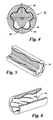
- the conventional Moineau motor 20 comprises a helically lobed rotor 22 disposed within a stator, the stator comprising a metal tube 24 having a circular, cylindrical interior wall 26 and a circular, cylindrical exterior wall 28, the interior wall having a molded elastomer liner 30 formed with helical lobes cooperable with the rotor to provide moving fluid chambers as the rotor rotates.
- the thickness of the elastomer liner varies because of the presence of the lobes.
- a Moineau Motor 32 in accordance with the invention, illustrated in FIGs. 4-6, comprises a helically lobed rotor 34 disposed within a stator comprising a tube 36 and a flexible liner 40.
- the tube 36 is composed of steel or a similar structural material.
- the tube has an interior wall 38 having helical lobes formed by electrochemical machining, and a circular, cylindrical exterior.
- the molded liner 40 of rubber or other suitable elastomer, is bonded to the interior wall of the stator after electrochemical machining.
- the elastomer liner which has a uniform thickness, defines the interior wall of the stator.
- the helically lobed interior wall of the stator cooperates with the helically lobed rotor 34 to define a set of fluid chambers, which move axially as the rotor rotates within the stator.
- the lobed interior wall 38 of the stator mechanically support the elastomer liner 40, strengthening the elastomer liner, and allowing it to withstand operating loads and stresses greater than those which can be withstood by elastomer liners of conventional Moineau motors.
- the lobes on the interior of the metal stator tube also provide the metal tube with an increased surface area enhancing the transfer of heat generated at the rotor/stator interface.
- frictional heat generated at the rotor/stator interface is conducted through a relatively insulative, but thin, elastomer layer, over a relatively large area, to a stator tube having a high thermal conductivity, from which the heat is dissipated to the environment.
- the relatively low, and uniform, thickness of the elastomeric liner 40 allows for a nearly even transfer of heat around the circumference of the liner.
- the nearly even transfer of heat results in a highly uniform temperature distribution, which prevents thermal distortion of the elastomeric liner and resulting disturbance to the proper operation of the motor.
- Patent 6,413,407 describes an electrochemical machining process in which every effort is made to yield the smoothest possible surface finish.
- an aft inner guide fixed to the aft end of the electrode provides a seal behind the electrode, sealing the tool to the workpiece behind the electrode as it moves through the workpiece. Water or another suitable fluid is then introduced behind the aft guide to flush away stray electrolyte.
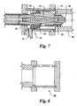
- electrolyte is introduced through port 42 into a proximal inlet flow box 44.
- the electrolyte passes over the length of the drive bar 48, between the drive bar and the finish machined portion 47 of the workpiece 46, and through slots 49 formed in the wall of a central opening of rear guide 50 which receives the drive bar.
- the slots 49 are preferably disposed parallel to one another, at intervals around the circumference of the central opening of the rear guide 50, as shown in FIG. 9. The flow of electrolyte through these slots allows for cooling of the cathode/drive bar interface.
- the electrolyte then passes over the cathode 52 in the proximal to distal direction, i.e., in the direction of cathode travel, past the front guide 80, and down the length of the unfinished bore 56 of the workpiece 46, into the distal exit flow box 58, where it is then discharged into an electrolyte return.
- the inlet flow box 44 must have an interior diameter, as shown in FIG. 7, equal to the major dimension of the finished profile of the workpiece, in order to support the weight of the cathode assembly before the rear guide enters the workpiece.
- the negative output terminal of a DC power supply preferably capable of delivering up to 30,000 Amperes at 25 volts, is connected to the workpiece, and the positive terminal is connected through a slip ring assembly to the drive bar.
- the exit flow box shown in FIG. 8, must have sufficient internal space to accept the cathode assembly as the cathode passes through the distal end of the workpiece. It must also be connected to the electrolyte flow system.
- the rear guide 50 directs electrolyte flow and supports the weight of the cathode assembly mounted on the drive bar 48, but does not serve a sealing function.
- An insulating sleeve 60 on the drive bar is cut back to location 62 to expose an annular area 64 of the drive bar of sufficient length to allow an electric current between the guide bar and the workpiece to exert an etching action on the finished interior wall of the workpiece.
- a standard machine tool taper 66 similar to a CAT 50, is used both to locate the cathode and guide assembly on the drive bar, and to conduct current from the drive bar to the cathode.
- the taper has two frusto-conical exterior surfaces mating respectively a frusto-conical interior surfaces in the drive bar and the cathodic electrode, to provide precise alignment and also to provide a large contact area for carrying the very high electric current required in electrochemical machining.
- an internal connector or clamping device, 68 is used to mount the cathode 52 on the drive bar 48.
- the connector 68 may be constructed of a hard metal having very good electrical conductivity, such as UNS-C18200.
- a double taper as shown, is preferred, a single taper, formed as an integral part of the drive bar, or as an integral part of the cathodic electrode could be used as an alternative.
- the cooling path can be isolated from the electrochemical machining process.
- coolant flows along passages 74 formed by flats machined in the surface of the drive bar and the interior wall of the insulating cover 60, then inward through radial passages 72 in the drive bar, and then in the reverse direction through the central passage 70 in the drive bar.
- the coolant can also flow in the opposite direction. This allows for a better temperature control of the drive bar at locations remote from the cathode.
- Electrolyte flow under the rear guide 50, through slots 49, is then used to conduct heat away from the exposed part 64 of the drive bar 48 so that relatively little heat needs to pass through the insulating cover 60 on the drive bar, which acts as not only as an electrical insulator, but also as a thermal insulator.
- a double flow rotary coupling (not shown) is used to inject cooling water into the chambers between the insulating cover and the flats on the outside of the drive bar.
- the coolant is directed to the central passage 70 of the bar, and is then allowed to exit the center of the bar at the proximal end through the double flow rotary coupling.
- O-ring seals 78 under the insulating cover at the distal end, and similar O-ring seals at the proximal end, ensure that the cooling liquid is maintained in the cooling chambers without contamination from the electrolyte.
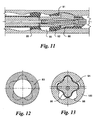
- the front guide 80 shown in FIGs. 7, 9, and 10, has a circular exterior to guide the cathode through the tubular workpiece before the lobes are machined in it, and to support the weight of the cathode assemble as it transverses the workpiece during the machining cycle.
- the front guide has longitudinal slots 82 cut through it to allow electrolyte to pass from the cathode to the exit flow box, one such slot 82, being shown in FIG. 10.
- the front guide is mounted on the cathode clamping device 54, and a threaded plug 84 is used to retain the front guide.
- a second seal 86 is provided behind the cathodic tool 88 to form an etching chamber 90.
- the electrolyte is channeled through the center of the drive bar used to push the cathode through the workpiece.
- the electrolyte is also channeled into a 360 degree slot adjacent seal 86.
- the electrolyte is forced through slots 91 formed in the rear seal 92, and across the cathodic tool 88 as in the preferred embodiment.
- This alternative embodiment provides better control over the amount of time during which the machine-finished finish interior surface of the workpiece is exposed to post-machining etching.
- the etching solution can be isolated from the electrolyte used in machining the lobes of the stator, in which case the composition of the etching solution can be different from that of the electrolyte.
- a second cathodic tool may be positioned in the etch chamber to direct the etching to particular regions within the etch chamber.
- a salt-based electrolyte such as a water based sodium chloride (NaCl) or sodium nitrate (NaNO 3 ) solution may be used.
- This process breaks down water into H 2 and OH ions that will bond with the metal ions, usually Fe, to form FeOH that precipitates out of the solution and can be filtered.
- the amount of current required to remove the metal electrochemically is directly proportional to the volume of metal removed in a given time interval. Therefore, the area 93, shown in FIG. 12, and the feed rate of the cathode determine the volume of metal removed and the amount of power required for the process.
- the maximum feed rate found practical to date is one inch per minute, because of the limiting dissolution rate of the metal. Increase in feed is possible by increasing the length of the cathode to increase the surface area being dissolved.
- the process is generally limited by resistance heating. It has been found that a 30,000 Ampere power supply is adequate for existing stator sizes. If larger stators are needed, larger power supplies and other conductors will be required.
- a typical stator machining process in accordance with the invention uses a NaNO 3 electrolyte, at a concentration of 2.2 pounds per gallon of water, at a neutral PH, and at an inlet pressure of 330 psi, and an outlet pressures of 80 to 150 psi.
- the electrolyte is introduced at a temperature of 105EF V 1EF.
- the voltage used is approximately 20 volts, although it may be varied from 10V to 25V.
- the feed rates vary from stator to stator, but an average part is produced at a feed rate of approximately 0.55 inches per minute. The feed rates will normally vary from .15 inches per minute on larger parts to 1 inch per minute on smaller parts. Cathode taper angles vary from 5E to 15E, but in most cases a 10E taper is preferred.
- a novel stator for a progressive cavity fluid mechanism in which the elastomer layer can be of uniform thickness, and very thin, so that it is less subject to damage resulting from thermal effects, and in which the exterior shape of the stator housing can be a simple circular cylinder, or any other desired shape.
- the stator is produced to precise dimensions by electrochemical machining, and, in the same process, the interior finish of the stator can be etched to promote secure bonding of the thin elastomer layer to the machined interior wall of the stator.
- a thin elastomer layer 94 of uniform thickness can be formed on the rotor 96, in which case it is unnecessary, and undesirable, to etch the interior surface 98 of the stator 100. Even in this alternative embodiment, many of the advantages of electrochemical machining of the stator can be realized.
Landscapes
- Engineering & Computer Science (AREA)
- Mechanical Engineering (AREA)
- Physics & Mathematics (AREA)
- Thermal Sciences (AREA)
- Chemical & Material Sciences (AREA)
- Chemical Kinetics & Catalysis (AREA)
- Electrochemistry (AREA)
- General Engineering & Computer Science (AREA)
- Electrical Discharge Machining, Electrochemical Machining, And Combined Machining (AREA)
- Rotary Pumps (AREA)
- Details And Applications Of Rotary Liquid Pumps (AREA)
Applications Claiming Priority (4)
| Application Number | Priority Date | Filing Date | Title |
|---|---|---|---|
| US51010703P | 2003-10-09 | 2003-10-09 | |
| US510107P | 2003-10-09 | ||
| US887189 | 2004-07-08 | ||
| US10/887,189 US7192260B2 (en) | 2003-10-09 | 2004-07-08 | Progressive cavity pump/motor stator, and apparatus and method to manufacture same by electrochemical machining |
Publications (2)
| Publication Number | Publication Date |
|---|---|
| EP1522366A1 true EP1522366A1 (fr) | 2005-04-13 |
| EP1522366B1 EP1522366B1 (fr) | 2007-11-14 |
Family
ID=34316853
Family Applications (1)
| Application Number | Title | Priority Date | Filing Date |
|---|---|---|---|
| EP04021414A Expired - Lifetime EP1522366B1 (fr) | 2003-10-09 | 2004-09-09 | Pompe à vis excentrique /moteur statator, et appareil et dispositif pour sa fabrication par usinage électrochimique. |
Country Status (5)
| Country | Link |
|---|---|
| US (2) | US7192260B2 (fr) |
| EP (1) | EP1522366B1 (fr) |
| AT (1) | ATE378134T1 (fr) |
| DE (1) | DE602004010030T2 (fr) |
| ES (1) | ES2297313T3 (fr) |
Cited By (6)
| Publication number | Priority date | Publication date | Assignee | Title |
|---|---|---|---|---|
| CN102501016A (zh) * | 2011-11-04 | 2012-06-20 | 中国海洋石油总公司 | 一种全金属螺杆泵定子的加工方法 |
| US8444901B2 (en) | 2007-12-31 | 2013-05-21 | Schlumberger Technology Corporation | Method of fabricating a high temperature progressive cavity motor or pump component |
| CN103433578A (zh) * | 2013-08-29 | 2013-12-11 | 沈阳公权水泵有限公司 | 超长导程多头型面螺旋管加工方法及机床 |
| CN104416330A (zh) * | 2013-08-30 | 2015-03-18 | 长江大学 | 金属螺杆钻具定子螺旋曲面内腔的分块数控加工方法 |
| US10480506B2 (en) | 2014-02-18 | 2019-11-19 | Vert Rotors Uk Limited | Conical screw machine with rotating inner and outer elements that are longitudinally fixed |
| CN111706504A (zh) * | 2016-04-18 | 2020-09-25 | 通用电气(Ge)贝克休斯有限责任公司 | 泥浆马达定子和泵以及制造方法 |
Families Citing this family (63)
| Publication number | Priority date | Publication date | Assignee | Title |
|---|---|---|---|---|
| US6881045B2 (en) * | 2003-06-19 | 2005-04-19 | Robbins & Myers Energy Systems, L.P. | Progressive cavity pump/motor |
| US7192260B2 (en) * | 2003-10-09 | 2007-03-20 | Lehr Precision, Inc. | Progressive cavity pump/motor stator, and apparatus and method to manufacture same by electrochemical machining |
| US7396220B2 (en) * | 2005-02-11 | 2008-07-08 | Dyna-Drill Technologies, Inc. | Progressing cavity stator including at least one cast longitudinal section |
| GB2424452B (en) * | 2005-03-22 | 2011-01-19 | Schlumberger Holdings | Progressive cavity motor with rotor having an elastomer sleeve |
| RU2373364C2 (ru) * | 2005-12-14 | 2009-11-20 | Общество с ограниченной ответственностью "Фирма "Радиус-Сервис" | Статор винтовой героторной гидромашины |
| US20080023123A1 (en) * | 2006-07-31 | 2008-01-31 | Schlumberger Technology Corporation | Automatic elastomer extrusion apparatus and method |
| EP2136962B1 (fr) * | 2007-04-18 | 2010-10-20 | National Oilwell Varco, L.P. | Procédé et systèmes d'entraînement de broche à long déport |
| US7950914B2 (en) | 2007-06-05 | 2011-05-31 | Smith International, Inc. | Braze or solder reinforced Moineau stator |
| US7878774B2 (en) | 2007-06-05 | 2011-02-01 | Smith International, Inc. | Moineau stator including a skeletal reinforcement |
| JP2010537095A (ja) * | 2007-08-17 | 2010-12-02 | ゼーペクス・ゲゼルシャフト・ミト・ベシュレンクテル・ハフツング | 分割されたステーターを有する偏心ねじポンプ |
| US8182252B2 (en) * | 2007-10-30 | 2012-05-22 | Moyno, Inc. | Progressing cavity pump with split stator |
| US20100006342A1 (en) * | 2008-07-11 | 2010-01-14 | Baker Hughes Incorporated | Method of making wellbore moineau devices |
| DE102008035393A1 (de) * | 2008-07-29 | 2010-02-11 | T-Mobile International Ag | Verfahren zur mehrfach hierarchischen Adressierung von Zellen in einem zellularen Kommunikationsnetz |
| GB0819794D0 (en) * | 2008-10-29 | 2008-12-03 | Nat Oilwell Varco Lp | Spindle drive systems and methods |
| DE102009010107B4 (de) * | 2009-02-21 | 2015-01-22 | Wilo Se | Exzenterschneckenpumpe |
| US8469104B2 (en) | 2009-09-09 | 2013-06-25 | Schlumberger Technology Corporation | Valves, bottom hole assemblies, and method of selectively actuating a motor |
| US8734141B2 (en) * | 2009-09-23 | 2014-05-27 | Halliburton Energy Services, P.C. | Stator/rotor assemblies having enhanced performance |
| US9347266B2 (en) * | 2009-11-13 | 2016-05-24 | Schlumberger Technology Corporation | Stator inserts, methods of fabricating the same, and downhole motors incorporating the same |
| US8777598B2 (en) | 2009-11-13 | 2014-07-15 | Schlumberger Technology Corporation | Stators for downwhole motors, methods for fabricating the same, and downhole motors incorporating the same |
| US20110116961A1 (en) | 2009-11-13 | 2011-05-19 | Hossein Akbari | Stators for downhole motors, methods for fabricating the same, and downhole motors incorporating the same |
| US8523545B2 (en) * | 2009-12-21 | 2013-09-03 | Baker Hughes Incorporated | Stator to housing lock in a progressing cavity pump |
| GB201001836D0 (en) * | 2010-02-04 | 2010-03-24 | Nat Oilwell Varco Lp | Stator manufacturing method |
| US9393648B2 (en) * | 2010-03-30 | 2016-07-19 | Smith International Inc. | Undercut stator for a positive displacment motor |
| CN101850449A (zh) * | 2010-04-17 | 2010-10-06 | 内蒙古北方重工业集团有限公司 | 螺杆钻具内螺旋预轮廓定子的制备方法及设备 |
| US9482223B2 (en) | 2010-11-19 | 2016-11-01 | Smith International, Inc. | Apparatus and method for controlling or limiting rotor orbit in moving cavity motors and pumps |
| GB201019614D0 (en) | 2010-11-19 | 2010-12-29 | Eatec Ltd | Apparatus and method for controlling or limiting rotor orbit in moving cavity motors and pumps |
| US9309884B2 (en) | 2010-11-29 | 2016-04-12 | Schlumberger Technology Corporation | Downhole motor or pump components, method of fabrication the same, and downhole motors incorporating the same |
| US8672656B2 (en) | 2010-12-20 | 2014-03-18 | Robbins & Myers Energy Systems L.P. | Progressing cavity pump/motor |
| CN102179584B (zh) * | 2011-06-02 | 2012-11-14 | 重庆望江工业有限公司 | 多头圆弧螺旋杆件的电解加工装置 |
| US8776916B2 (en) | 2011-07-01 | 2014-07-15 | Baker Hughes Incorporated | Drilling motors with elastically deformable lobes |
| US9540545B2 (en) * | 2011-09-02 | 2017-01-10 | Schlumberger Technology Corporation | Plasma treatment in fabricating directional drilling assemblies |
| GB2551304B (en) * | 2012-02-22 | 2018-02-28 | Nat Oilwell Varco Lp | Stator for progressive cavity pump/motor |
| US10309395B2 (en) * | 2013-03-05 | 2019-06-04 | Smith International, Inc. | Method and apparatus to manufacture a progressive cavity motor or pump |
| DE102013206472A1 (de) * | 2013-04-11 | 2014-10-30 | Gerhard Kohler | Vorrichtung und Verfahren zur Herstellung eines Werkstücks mittels elektrochemischer Abtragung |
| US9133841B2 (en) | 2013-04-11 | 2015-09-15 | Cameron International Corporation | Progressing cavity stator with metal plates having apertures with englarged ends |
| US20160208798A1 (en) * | 2013-08-23 | 2016-07-21 | University Of Florida Research Foundation, Inc. | Adjustable interference progressive cavity pump/motor for predictive wear |
| US20150122549A1 (en) * | 2013-11-05 | 2015-05-07 | Baker Hughes Incorporated | Hydraulic tools, drilling systems including hydraulic tools, and methods of using hydraulic tools |
| US9610611B2 (en) | 2014-02-12 | 2017-04-04 | Baker Hughes Incorporated | Method of lining an inner surface of a tubular and system for doing same |
| RU2578895C2 (ru) * | 2014-03-14 | 2016-03-27 | Общество с ограниченной ответственностью фирма "Радиус-Сервис" | Установка для электрохимической обработки винтового зубчатого профиля внутренней поверхности в отверстии трубчатой заготовки |
| US9976227B2 (en) | 2014-05-15 | 2018-05-22 | Baker Hughes, A Ge Company, Llc | Electrochemical machining method for rotors or stators for moineau pumps |
| RU2586365C1 (ru) * | 2014-11-17 | 2016-06-10 | Общество с ограниченной ответственностью "Фирма "Радиус-Сервис" | Электродный блок для электрохимической обработки винтового зубчатого профиля в отверстии трубчатой заготовки |
| KR101714157B1 (ko) * | 2015-06-08 | 2017-03-08 | 현대자동차주식회사 | 금형장치 |
| US9896885B2 (en) * | 2015-12-10 | 2018-02-20 | Baker Hughes Incorporated | Hydraulic tools including removable coatings, drilling systems, and methods of making and using hydraulic tools |
| CA2961629A1 (fr) * | 2017-03-22 | 2018-09-22 | Infocus Energy Services Inc. | Systemes, dispositifs, assemblages d'alesage et methodes d'utilisation associees |
| RU2663789C1 (ru) * | 2017-04-19 | 2018-08-09 | Общество с ограниченной ответственностью "Фирма "Радиус-Сервис" | Электродный блок для электрохимической обработки винтового зубчатого профиля в отверстии трубчатой заготовки |
| US10612381B2 (en) | 2017-05-30 | 2020-04-07 | Reme Technologies, Llc | Mud motor inverse power section |
| CN107626998B (zh) * | 2017-10-24 | 2024-07-05 | 西安昆仑工业(集团)有限责任公司 | 200毫米口径等壁厚螺杆钻具定子内螺旋电解加工阴极 |
| US11148327B2 (en) | 2018-03-29 | 2021-10-19 | Baker Hughes, A Ge Company, Llc | Method for forming a mud motor stator |
| CN109236559B (zh) * | 2018-08-20 | 2021-04-30 | 中海石油(中国)有限公司上海分公司 | 一种螺杆马达及井下动力钻具 |
| RU2709881C1 (ru) * | 2019-03-06 | 2019-12-23 | Общество с ограниченной ответственностью "Фирма "Радиус-Сервис" | Электродный блок для электрохимической обработки винтового зубчатого профиля в отверстии трубчатой заготовки |
| RU2710092C1 (ru) * | 2019-05-06 | 2019-12-24 | Общество с ограниченной ответственностью "Фирма "Радиус-Сервис" | Установка для электрохимической обработки винтового зубчатого профиля внутренней поверхности в отверстии трубчатой заготовки |
| US11371503B2 (en) | 2019-12-16 | 2022-06-28 | Saudi Arabian Oil Company | Smart drilling motor stator |
| RU2745677C1 (ru) * | 2020-02-25 | 2021-03-30 | Общество с ограниченной ответственностью "Фирма "Радиус-Сервис" | Статор винтовой героторной гидромашины |
| US11421533B2 (en) | 2020-04-02 | 2022-08-23 | Abaco Drilling Technologies Llc | Tapered stators in positive displacement motors remediating effects of rotor tilt |
| CA3114159A1 (fr) | 2020-04-02 | 2021-10-02 | Abaco Drilling Technologies Llc | Stators coniques dans des moteurs a deplacement direct pour corriger les effets de l'inclinaison du rotor |
| DE102020004334A1 (de) | 2020-07-20 | 2022-01-20 | Wilhelm Kächele GmbH | Stator für Exzenterschneckenmaschine |
| NL2028842B1 (en) * | 2021-07-26 | 2023-01-31 | Mm Innovations B V | Motor/pump assembly for driving downhole tooling and method for manufacturing such motor/pump assembly |
| WO2023008999A1 (fr) * | 2021-07-26 | 2023-02-02 | Mm Innovations B.V. | Ensemble moteur/pompe pour entraîner un outillage de fond de trou et procédé de fabrication d'un tel ensemble moteur/pompe |
| DE102021130260A1 (de) | 2021-11-19 | 2023-05-25 | Wilhelm Kächele GmbH | Stator für Exenterschneckenmaschine sowie Herstellungsverfahren für diesen |
| US11788356B2 (en) | 2021-11-23 | 2023-10-17 | Halliburton Energy Services, Inc. | Optimized adhesive thickness for metal-to-elastomer bonding in oilfield mud motor and pump stators |
| US12152588B1 (en) * | 2023-05-26 | 2024-11-26 | Grant Prideco, Inc. | Free-mold stator for a progressing cavity pump |
| CN117464107B (zh) * | 2023-11-08 | 2025-07-18 | 深圳市星宏精密电解科技有限公司 | 一种工件内滚道的电解加工方法 |
| DE102024112515A1 (de) * | 2024-05-03 | 2025-11-06 | Extrude Hone Gmbh | Rifling-Kathode, Verfahren und Vorrichtung |
Citations (5)
| Publication number | Priority date | Publication date | Assignee | Title |
|---|---|---|---|---|
| FR1592149A (fr) * | 1967-11-02 | 1970-05-11 | ||
| GB1281117A (en) * | 1969-04-02 | 1972-07-12 | Kernforschung Gmbh Ges Fuer | Apparatus for electrolytic machining |
| US5171138A (en) * | 1990-12-20 | 1992-12-15 | Drilex Systems, Inc. | Composite stator construction for downhole drilling motors |
| US6413407B1 (en) * | 2000-11-27 | 2002-07-02 | Lehr Precision, Inc. | Fluted electrochemical machining |
| US6543132B1 (en) * | 1997-12-18 | 2003-04-08 | Baker Hughes Incorporated | Methods of making mud motors |
Family Cites Families (35)
| Publication number | Priority date | Publication date | Assignee | Title |
|---|---|---|---|---|
| US3084631A (en) | 1962-01-17 | 1963-04-09 | Robbins & Myers | Helical gear pump with stator compression |
| US3616343A (en) | 1964-08-08 | 1971-10-26 | Inoue K | Electrochemical machining method |
| US3547798A (en) | 1967-03-29 | 1970-12-15 | Cincinnati Milacron Inc | Electrochemical machining tool |
| US3499830A (en) | 1967-11-20 | 1970-03-10 | Cincinnati Milling Machine Co | Apparatus for electrochemically forming and finishing gears |
| US3553095A (en) | 1967-12-18 | 1971-01-05 | Lear Siegler Inc | Method and apparatus for ecm gear finishing |
| US3769194A (en) | 1969-08-18 | 1973-10-30 | Cincinnati Milacron Inc | Apparatus and method for forming grooves and lands |
| US3896012A (en) | 1972-06-27 | 1975-07-22 | Polygraph Leipzig | Electrochemical metal-removal method |
| FR2343906A1 (fr) | 1976-03-09 | 1977-10-07 | Mecanique Metallurgie Ste Gle | Perfectionnements aux stators de pompes a vis |
| US4250371A (en) | 1979-01-22 | 1981-02-10 | Barber-Colman Company | Accurate production of relieved shapes by electrical erosion |
| US4376020A (en) | 1980-12-24 | 1983-03-08 | Electrodrill, Inc. | Method of and apparatus for cutting narrow grooves |
| US4475996A (en) | 1982-03-03 | 1984-10-09 | Inoue-Japax Research Incorporated | Multi-strand wire electroerosion machining method and apparatus |
| US4486279A (en) | 1983-05-12 | 1984-12-04 | Westinghouse Electric Corp. | Apparatus and method for making a laminated core |
| US4676725A (en) | 1985-12-27 | 1987-06-30 | Hughes Tool Company | Moineau type gear mechanism with resilient sleeve |
| US6183226B1 (en) | 1986-04-24 | 2001-02-06 | Steven M. Wood | Progressive cavity motors using composite materials |
| US4690737A (en) | 1986-06-10 | 1987-09-01 | Cation Corporation | Electrochemical rifling of gun barrels |
| DE3712354A1 (de) * | 1986-11-08 | 1988-05-11 | Wankel Gmbh | Rotationskolbengeblaese |
| US4851090A (en) | 1987-05-13 | 1989-07-25 | General Electric Company | Method and apparatus for electrochemically machining airfoil blades |
| WO1990004665A1 (fr) | 1988-10-25 | 1990-05-03 | Belorussky Politekhnichesky Institut | Dispositif pour traitement electrochimique d'articles |
| US4997534A (en) | 1989-02-13 | 1991-03-05 | General Electric Company | Electrochemical machining with avoidance of erosion |
| US5004529A (en) | 1989-10-18 | 1991-04-02 | Robert Bosch Gmbh | Electrochemical etching apparatus |
| US5016460A (en) | 1989-12-22 | 1991-05-21 | Inco Alloys International, Inc. | Durable method for producing finned tubing |
| US5002643A (en) | 1990-01-05 | 1991-03-26 | Andrews James D | Electrode with outside flow of electrolyte for electrochemical machining and method |
| DE4132330A1 (de) * | 1990-11-23 | 1992-05-27 | Lacks Ind Inc | Verfahren zum elektroplattieren hochschlagfester kunststoffe |
| GB2254279B (en) | 1991-02-07 | 1994-08-17 | Rolls Royce Plc | Improvements in or relating to electrochemical machining |
| US5320505A (en) * | 1993-03-04 | 1994-06-14 | Tecumseh Products Company | Electrochemical machining of scroll wraps |
| US5759019A (en) | 1994-02-14 | 1998-06-02 | Steven M. Wood | Progressive cavity pumps using composite materials |
| WO1999051381A2 (fr) | 1998-04-06 | 1999-10-14 | Koninklijke Philips Electronics N.V. | Procede d'usinage electrochimique d'une piece et appareillage correspondant |
| BR9906345A (pt) | 1998-04-06 | 2000-09-26 | Koninkl Philips Electronics Nv | Processo e arranjo para usinar eletroquimicamente uma peça condutora elétrica, e, fonte de suprimento de energia elétrica para uso no mencionado processo. |
| US6309195B1 (en) | 1998-06-05 | 2001-10-30 | Halliburton Energy Services, Inc. | Internally profiled stator tube |
| DE59810471D1 (de) | 1998-08-07 | 2004-01-29 | Fritz-Herbert Frembgen | Verfahren und Vorrichtung zum elektrochemischen Bearbeiten von Werkstücken |
| GB2340911B (en) | 1998-08-20 | 2000-11-15 | Doncasters Plc | Alloy pipes and methods of making same |
| FR2794498B1 (fr) | 1999-06-07 | 2001-06-29 | Inst Francais Du Petrole | Pompe a cavites progressantes a stator composite et son procede de fabrication |
| US6464855B1 (en) | 2000-10-04 | 2002-10-15 | Speedfam-Ipec Corporation | Method and apparatus for electrochemical planarization of a workpiece |
| US6866769B2 (en) | 2001-11-14 | 2005-03-15 | General Electric Company | Drive head and ECM method and tool for making same |
| US7192260B2 (en) * | 2003-10-09 | 2007-03-20 | Lehr Precision, Inc. | Progressive cavity pump/motor stator, and apparatus and method to manufacture same by electrochemical machining |
-
2004
- 2004-07-08 US US10/887,189 patent/US7192260B2/en not_active Expired - Lifetime
- 2004-09-09 EP EP04021414A patent/EP1522366B1/fr not_active Expired - Lifetime
- 2004-09-09 AT AT04021414T patent/ATE378134T1/de not_active IP Right Cessation
- 2004-09-09 ES ES04021414T patent/ES2297313T3/es not_active Expired - Lifetime
- 2004-09-09 DE DE602004010030T patent/DE602004010030T2/de not_active Expired - Lifetime
-
2007
- 2007-02-09 US US11/704,299 patent/US20070140883A1/en not_active Abandoned
Patent Citations (5)
| Publication number | Priority date | Publication date | Assignee | Title |
|---|---|---|---|---|
| FR1592149A (fr) * | 1967-11-02 | 1970-05-11 | ||
| GB1281117A (en) * | 1969-04-02 | 1972-07-12 | Kernforschung Gmbh Ges Fuer | Apparatus for electrolytic machining |
| US5171138A (en) * | 1990-12-20 | 1992-12-15 | Drilex Systems, Inc. | Composite stator construction for downhole drilling motors |
| US6543132B1 (en) * | 1997-12-18 | 2003-04-08 | Baker Hughes Incorporated | Methods of making mud motors |
| US6413407B1 (en) * | 2000-11-27 | 2002-07-02 | Lehr Precision, Inc. | Fluted electrochemical machining |
Cited By (9)
| Publication number | Priority date | Publication date | Assignee | Title |
|---|---|---|---|---|
| US8444901B2 (en) | 2007-12-31 | 2013-05-21 | Schlumberger Technology Corporation | Method of fabricating a high temperature progressive cavity motor or pump component |
| CN101960145B (zh) * | 2007-12-31 | 2013-09-11 | 普拉德研究及开发股份有限公司 | 高温螺杆马达或泵部件以及制造方法 |
| CN102501016A (zh) * | 2011-11-04 | 2012-06-20 | 中国海洋石油总公司 | 一种全金属螺杆泵定子的加工方法 |
| CN103433578A (zh) * | 2013-08-29 | 2013-12-11 | 沈阳公权水泵有限公司 | 超长导程多头型面螺旋管加工方法及机床 |
| CN103433578B (zh) * | 2013-08-29 | 2016-06-08 | 沈阳公权水泵有限公司 | 超长导程多头型面螺旋管加工方法及机床 |
| CN104416330A (zh) * | 2013-08-30 | 2015-03-18 | 长江大学 | 金属螺杆钻具定子螺旋曲面内腔的分块数控加工方法 |
| US10480506B2 (en) | 2014-02-18 | 2019-11-19 | Vert Rotors Uk Limited | Conical screw machine with rotating inner and outer elements that are longitudinally fixed |
| US10962004B2 (en) | 2014-02-18 | 2021-03-30 | Vert Rotors Uk Limited | Synchronized conical screw compressor or pump |
| CN111706504A (zh) * | 2016-04-18 | 2020-09-25 | 通用电气(Ge)贝克休斯有限责任公司 | 泥浆马达定子和泵以及制造方法 |
Also Published As
| Publication number | Publication date |
|---|---|
| ATE378134T1 (de) | 2007-11-15 |
| US20070140883A1 (en) | 2007-06-21 |
| HK1077037A1 (en) | 2006-02-03 |
| DE602004010030D1 (de) | 2007-12-27 |
| US7192260B2 (en) | 2007-03-20 |
| EP1522366B1 (fr) | 2007-11-14 |
| US20050079083A1 (en) | 2005-04-14 |
| DE602004010030T2 (de) | 2008-09-18 |
| ES2297313T3 (es) | 2008-05-01 |
Similar Documents
| Publication | Publication Date | Title |
|---|---|---|
| US7192260B2 (en) | Progressive cavity pump/motor stator, and apparatus and method to manufacture same by electrochemical machining | |
| US6881045B2 (en) | Progressive cavity pump/motor | |
| WO2002042030A2 (fr) | Usinage electrochimique a cannelures | |
| WO2001044615A2 (fr) | Stator composite destine a des moteurs de forage et son procede de construction | |
| CA2794501C (fr) | Stator degage pour moteur volumetrique | |
| CN109277654B (zh) | 旋印电解加工封液装置与方法 | |
| CA2504529C (fr) | Pompe a cavite progressive/stator de moteur, et appareil et methode de fabrication par usinage electrochimique | |
| US20100320078A1 (en) | Electroerosion spindle assembly | |
| HK1077037B (en) | Progressive cavity pump / motor stator, and apparatus and method to manufacture same by electrochemical machining | |
| US5818006A (en) | Surface preparation electrical discharge apparatus and method | |
| EP1522367B1 (fr) | Usinage par électrochimie de barres | |
| RU2663789C1 (ru) | Электродный блок для электрохимической обработки винтового зубчатого профиля в отверстии трубчатой заготовки | |
| RU2709881C1 (ru) | Электродный блок для электрохимической обработки винтового зубчатого профиля в отверстии трубчатой заготовки | |
| KR20060045632A (ko) | 추진 공동형 펌프/모터 스테이터 및 전기 화학식 가공에의해 이를 제조하기 위한 장치 및 방법 | |
| US4650549A (en) | Method for electroplating helical rotors | |
| GB2162454A (en) | Method of manufacturing internally-toothed bevel gear and apparatus therefor | |
| RU2578895C2 (ru) | Установка для электрохимической обработки винтового зубчатого профиля внутренней поверхности в отверстии трубчатой заготовки | |
| RU2774193C1 (ru) | Электродный блок для электрохимической обработки винтового зубчатого профиля в отверстии трубчатой заготовки | |
| CN118148505A (zh) | 一种可旋转切屑齿智能化钻头 | |
| US20100006342A1 (en) | Method of making wellbore moineau devices | |
| RU2774195C1 (ru) | Электродный блок для электрохимической обработки винтового зубчатого профиля в отверстии трубчатой заготовки | |
| HK1077036B (en) | Ecm trepan of bars | |
| RU2710092C1 (ru) | Установка для электрохимической обработки винтового зубчатого профиля внутренней поверхности в отверстии трубчатой заготовки | |
| RU2798263C1 (ru) | Электродный блок для электрохимической обработки винтового зубчатого профиля в отверстии трубчатой заготовки одновинтового насоса | |
| CN115596346B (zh) | 一种具有排料功能的螺杆钻具 |
Legal Events
| Date | Code | Title | Description |
|---|---|---|---|
| PUAI | Public reference made under article 153(3) epc to a published international application that has entered the european phase |
Free format text: ORIGINAL CODE: 0009012 |
|
| AK | Designated contracting states |
Kind code of ref document: A1 Designated state(s): AT BE BG CH CY CZ DE DK EE ES FI FR GB GR HU IE IT LI LU MC NL PL PT RO SE SI SK TR |
|
| AX | Request for extension of the european patent |
Extension state: AL HR LT LV MK |
|
| 17P | Request for examination filed |
Effective date: 20050720 |
|
| AKX | Designation fees paid |
Designated state(s): AT BE BG CH CY CZ DE DK EE ES FI FR GB GR HU IE IT LI LU MC NL PL PT RO SE SI SK TR |
|
| REG | Reference to a national code |
Ref country code: HK Ref legal event code: DE Ref document number: 1077037 Country of ref document: HK |
|
| 17Q | First examination report despatched |
Effective date: 20051013 |
|
| GRAP | Despatch of communication of intention to grant a patent |
Free format text: ORIGINAL CODE: EPIDOSNIGR1 |
|
| GRAJ | Information related to disapproval of communication of intention to grant by the applicant or resumption of examination proceedings by the epo deleted |
Free format text: ORIGINAL CODE: EPIDOSDIGR1 |
|
| GRAP | Despatch of communication of intention to grant a patent |
Free format text: ORIGINAL CODE: EPIDOSNIGR1 |
|
| GRAS | Grant fee paid |
Free format text: ORIGINAL CODE: EPIDOSNIGR3 |
|
| GRAA | (expected) grant |
Free format text: ORIGINAL CODE: 0009210 |
|
| AK | Designated contracting states |
Kind code of ref document: B1 Designated state(s): AT BE BG CH CY CZ DE DK EE ES FI FR GB GR HU IE IT LI LU MC NL PL PT RO SE SI SK TR |
|
| REG | Reference to a national code |
Ref country code: GB Ref legal event code: FG4D |
|
| REG | Reference to a national code |
Ref country code: CH Ref legal event code: EP |
|
| REG | Reference to a national code |
Ref country code: IE Ref legal event code: FG4D |
|
| REF | Corresponds to: |
Ref document number: 602004010030 Country of ref document: DE Date of ref document: 20071227 Kind code of ref document: P |
|
| PG25 | Lapsed in a contracting state [announced via postgrant information from national office to epo] |
Ref country code: SE Free format text: LAPSE BECAUSE OF FAILURE TO SUBMIT A TRANSLATION OF THE DESCRIPTION OR TO PAY THE FEE WITHIN THE PRESCRIBED TIME-LIMIT Effective date: 20080214 Ref country code: CH Free format text: LAPSE BECAUSE OF FAILURE TO SUBMIT A TRANSLATION OF THE DESCRIPTION OR TO PAY THE FEE WITHIN THE PRESCRIBED TIME-LIMIT Effective date: 20071114 Ref country code: LI Free format text: LAPSE BECAUSE OF FAILURE TO SUBMIT A TRANSLATION OF THE DESCRIPTION OR TO PAY THE FEE WITHIN THE PRESCRIBED TIME-LIMIT Effective date: 20071114 |
|
| REG | Reference to a national code |
Ref country code: ES Ref legal event code: FG2A Ref document number: 2297313 Country of ref document: ES Kind code of ref document: T3 |
|
| PG25 | Lapsed in a contracting state [announced via postgrant information from national office to epo] |
Ref country code: FI Free format text: LAPSE BECAUSE OF FAILURE TO SUBMIT A TRANSLATION OF THE DESCRIPTION OR TO PAY THE FEE WITHIN THE PRESCRIBED TIME-LIMIT Effective date: 20071114 Ref country code: SI Free format text: LAPSE BECAUSE OF FAILURE TO SUBMIT A TRANSLATION OF THE DESCRIPTION OR TO PAY THE FEE WITHIN THE PRESCRIBED TIME-LIMIT Effective date: 20071114 Ref country code: PL Free format text: LAPSE BECAUSE OF FAILURE TO SUBMIT A TRANSLATION OF THE DESCRIPTION OR TO PAY THE FEE WITHIN THE PRESCRIBED TIME-LIMIT Effective date: 20071114 Ref country code: BG Free format text: LAPSE BECAUSE OF FAILURE TO SUBMIT A TRANSLATION OF THE DESCRIPTION OR TO PAY THE FEE WITHIN THE PRESCRIBED TIME-LIMIT Effective date: 20080214 |
|
| REG | Reference to a national code |
Ref country code: CH Ref legal event code: PL |
|
| PG25 | Lapsed in a contracting state [announced via postgrant information from national office to epo] |
Ref country code: AT Free format text: LAPSE BECAUSE OF FAILURE TO SUBMIT A TRANSLATION OF THE DESCRIPTION OR TO PAY THE FEE WITHIN THE PRESCRIBED TIME-LIMIT Effective date: 20071114 |
|
| PG25 | Lapsed in a contracting state [announced via postgrant information from national office to epo] |
Ref country code: CZ Free format text: LAPSE BECAUSE OF FAILURE TO SUBMIT A TRANSLATION OF THE DESCRIPTION OR TO PAY THE FEE WITHIN THE PRESCRIBED TIME-LIMIT Effective date: 20071114 Ref country code: DK Free format text: LAPSE BECAUSE OF FAILURE TO SUBMIT A TRANSLATION OF THE DESCRIPTION OR TO PAY THE FEE WITHIN THE PRESCRIBED TIME-LIMIT Effective date: 20071114 |
|
| ET | Fr: translation filed | ||
| REG | Reference to a national code |
Ref country code: HK Ref legal event code: GR Ref document number: 1077037 Country of ref document: HK |
|
| PG25 | Lapsed in a contracting state [announced via postgrant information from national office to epo] |
Ref country code: SK Free format text: LAPSE BECAUSE OF FAILURE TO SUBMIT A TRANSLATION OF THE DESCRIPTION OR TO PAY THE FEE WITHIN THE PRESCRIBED TIME-LIMIT Effective date: 20071114 Ref country code: BE Free format text: LAPSE BECAUSE OF FAILURE TO SUBMIT A TRANSLATION OF THE DESCRIPTION OR TO PAY THE FEE WITHIN THE PRESCRIBED TIME-LIMIT Effective date: 20071114 Ref country code: RO Free format text: LAPSE BECAUSE OF FAILURE TO SUBMIT A TRANSLATION OF THE DESCRIPTION OR TO PAY THE FEE WITHIN THE PRESCRIBED TIME-LIMIT Effective date: 20071114 |
|
| PLBE | No opposition filed within time limit |
Free format text: ORIGINAL CODE: 0009261 |
|
| STAA | Information on the status of an ep patent application or granted ep patent |
Free format text: STATUS: NO OPPOSITION FILED WITHIN TIME LIMIT |
|
| PG25 | Lapsed in a contracting state [announced via postgrant information from national office to epo] |
Ref country code: PT Free format text: LAPSE BECAUSE OF FAILURE TO SUBMIT A TRANSLATION OF THE DESCRIPTION OR TO PAY THE FEE WITHIN THE PRESCRIBED TIME-LIMIT Effective date: 20080414 |
|
| 26N | No opposition filed |
Effective date: 20080815 |
|
| PG25 | Lapsed in a contracting state [announced via postgrant information from national office to epo] |
Ref country code: GR Free format text: LAPSE BECAUSE OF FAILURE TO SUBMIT A TRANSLATION OF THE DESCRIPTION OR TO PAY THE FEE WITHIN THE PRESCRIBED TIME-LIMIT Effective date: 20080215 |
|
| PG25 | Lapsed in a contracting state [announced via postgrant information from national office to epo] |
Ref country code: MC Free format text: LAPSE BECAUSE OF NON-PAYMENT OF DUE FEES Effective date: 20080930 Ref country code: EE Free format text: LAPSE BECAUSE OF FAILURE TO SUBMIT A TRANSLATION OF THE DESCRIPTION OR TO PAY THE FEE WITHIN THE PRESCRIBED TIME-LIMIT Effective date: 20071114 |
|
| PG25 | Lapsed in a contracting state [announced via postgrant information from national office to epo] |
Ref country code: CY Free format text: LAPSE BECAUSE OF FAILURE TO SUBMIT A TRANSLATION OF THE DESCRIPTION OR TO PAY THE FEE WITHIN THE PRESCRIBED TIME-LIMIT Effective date: 20071114 Ref country code: IE Free format text: LAPSE BECAUSE OF NON-PAYMENT OF DUE FEES Effective date: 20080909 |
|
| PGFP | Annual fee paid to national office [announced via postgrant information from national office to epo] |
Ref country code: DE Payment date: 20091028 Year of fee payment: 6 Ref country code: ES Payment date: 20091026 Year of fee payment: 6 |
|
| PGFP | Annual fee paid to national office [announced via postgrant information from national office to epo] |
Ref country code: NL Payment date: 20091024 Year of fee payment: 6 |
|
| PGFP | Annual fee paid to national office [announced via postgrant information from national office to epo] |
Ref country code: FR Payment date: 20091029 Year of fee payment: 6 |
|
| PG25 | Lapsed in a contracting state [announced via postgrant information from national office to epo] |
Ref country code: HU Free format text: LAPSE BECAUSE OF FAILURE TO SUBMIT A TRANSLATION OF THE DESCRIPTION OR TO PAY THE FEE WITHIN THE PRESCRIBED TIME-LIMIT Effective date: 20080515 Ref country code: LU Free format text: LAPSE BECAUSE OF NON-PAYMENT OF DUE FEES Effective date: 20080909 |
|
| PG25 | Lapsed in a contracting state [announced via postgrant information from national office to epo] |
Ref country code: TR Free format text: LAPSE BECAUSE OF FAILURE TO SUBMIT A TRANSLATION OF THE DESCRIPTION OR TO PAY THE FEE WITHIN THE PRESCRIBED TIME-LIMIT Effective date: 20071114 |
|
| PG25 | Lapsed in a contracting state [announced via postgrant information from national office to epo] |
Ref country code: IT Free format text: LAPSE BECAUSE OF NON-PAYMENT OF DUE FEES Effective date: 20080930 |
|
| REG | Reference to a national code |
Ref country code: NL Ref legal event code: V1 Effective date: 20110401 |
|
| REG | Reference to a national code |
Ref country code: FR Ref legal event code: ST Effective date: 20110531 |
|
| REG | Reference to a national code |
Ref country code: DE Ref legal event code: R119 Ref document number: 602004010030 Country of ref document: DE Effective date: 20110401 |
|
| PG25 | Lapsed in a contracting state [announced via postgrant information from national office to epo] |
Ref country code: FR Free format text: LAPSE BECAUSE OF NON-PAYMENT OF DUE FEES Effective date: 20100930 Ref country code: DE Free format text: LAPSE BECAUSE OF NON-PAYMENT OF DUE FEES Effective date: 20110401 |
|
| PG25 | Lapsed in a contracting state [announced via postgrant information from national office to epo] |
Ref country code: NL Free format text: LAPSE BECAUSE OF NON-PAYMENT OF DUE FEES Effective date: 20110401 |
|
| REG | Reference to a national code |
Ref country code: ES Ref legal event code: FD2A Effective date: 20111019 |
|
| PG25 | Lapsed in a contracting state [announced via postgrant information from national office to epo] |
Ref country code: ES Free format text: LAPSE BECAUSE OF NON-PAYMENT OF DUE FEES Effective date: 20100910 |
|
| PGFP | Annual fee paid to national office [announced via postgrant information from national office to epo] |
Ref country code: GB Payment date: 20230927 Year of fee payment: 20 |
|
| REG | Reference to a national code |
Ref country code: GB Ref legal event code: PE20 Expiry date: 20240908 |
|
| PG25 | Lapsed in a contracting state [announced via postgrant information from national office to epo] |
Ref country code: GB Free format text: LAPSE BECAUSE OF EXPIRATION OF PROTECTION Effective date: 20240908 |
|
| PG25 | Lapsed in a contracting state [announced via postgrant information from national office to epo] |
Ref country code: GB Free format text: LAPSE BECAUSE OF EXPIRATION OF PROTECTION Effective date: 20240908 |