EP1522367B1 - Usinage par électrochimie de barres - Google Patents
Usinage par électrochimie de barres Download PDFInfo
- Publication number
- EP1522367B1 EP1522367B1 EP04021415A EP04021415A EP1522367B1 EP 1522367 B1 EP1522367 B1 EP 1522367B1 EP 04021415 A EP04021415 A EP 04021415A EP 04021415 A EP04021415 A EP 04021415A EP 1522367 B1 EP1522367 B1 EP 1522367B1
- Authority
- EP
- European Patent Office
- Prior art keywords
- workpiece
- passage
- cathodic tool
- tool
- cathodic
- Prior art date
- Legal status (The legal status is an assumption and is not a legal conclusion. Google has not performed a legal analysis and makes no representation as to the accuracy of the status listed.)
- Expired - Lifetime
Links
- 241000425571 Trepanes Species 0.000 title claims description 8
- 239000003792 electrolyte Substances 0.000 claims abstract description 50
- 230000007246 mechanism Effects 0.000 claims abstract description 9
- 230000007704 transition Effects 0.000 claims abstract description 6
- 238000003754 machining Methods 0.000 claims description 15
- 238000000034 method Methods 0.000 claims description 14
- 230000033001 locomotion Effects 0.000 claims description 3
- 230000003134 recirculating effect Effects 0.000 claims 1
- 230000000750 progressive effect Effects 0.000 description 17
- XLYOFNOQVPJJNP-UHFFFAOYSA-N water Substances O XLYOFNOQVPJJNP-UHFFFAOYSA-N 0.000 description 10
- FAPWRFPIFSIZLT-UHFFFAOYSA-M Sodium chloride Chemical compound [Na+].[Cl-] FAPWRFPIFSIZLT-UHFFFAOYSA-M 0.000 description 6
- 239000012530 fluid Substances 0.000 description 6
- VWDWKYIASSYTQR-UHFFFAOYSA-N sodium nitrate Chemical compound [Na+].[O-][N+]([O-])=O VWDWKYIASSYTQR-UHFFFAOYSA-N 0.000 description 6
- 239000000463 material Substances 0.000 description 5
- 230000008569 process Effects 0.000 description 5
- 238000004519 manufacturing process Methods 0.000 description 4
- 238000003801 milling Methods 0.000 description 4
- VYZAMTAEIAYCRO-UHFFFAOYSA-N Chromium Chemical compound [Cr] VYZAMTAEIAYCRO-UHFFFAOYSA-N 0.000 description 3
- 238000005520 cutting process Methods 0.000 description 3
- 238000005553 drilling Methods 0.000 description 3
- 238000005086 pumping Methods 0.000 description 3
- 239000011780 sodium chloride Substances 0.000 description 3
- 230000009471 action Effects 0.000 description 2
- 230000015556 catabolic process Effects 0.000 description 2
- 229910052804 chromium Inorganic materials 0.000 description 2
- 239000011651 chromium Substances 0.000 description 2
- 229920001971 elastomer Polymers 0.000 description 2
- 239000000806 elastomer Substances 0.000 description 2
- 239000007789 gas Substances 0.000 description 2
- 239000000203 mixture Substances 0.000 description 2
- 238000007747 plating Methods 0.000 description 2
- 238000005498 polishing Methods 0.000 description 2
- 229910001256 stainless steel alloy Inorganic materials 0.000 description 2
- 238000013519 translation Methods 0.000 description 2
- DHKHKXVYLBGOIT-UHFFFAOYSA-N 1,1-Diethoxyethane Chemical compound CCOC(C)OCC DHKHKXVYLBGOIT-UHFFFAOYSA-N 0.000 description 1
- RYGMFSIKBFXOCR-UHFFFAOYSA-N Copper Chemical compound [Cu] RYGMFSIKBFXOCR-UHFFFAOYSA-N 0.000 description 1
- 229920004943 Delrin® Polymers 0.000 description 1
- UFHFLCQGNIYNRP-UHFFFAOYSA-N Hydrogen Chemical compound [H][H] UFHFLCQGNIYNRP-UHFFFAOYSA-N 0.000 description 1
- 229910000831 Steel Inorganic materials 0.000 description 1
- 239000011354 acetal resin Substances 0.000 description 1
- 238000013459 approach Methods 0.000 description 1
- 230000015572 biosynthetic process Effects 0.000 description 1
- 230000008859 change Effects 0.000 description 1
- 238000006243 chemical reaction Methods 0.000 description 1
- 239000004020 conductor Substances 0.000 description 1
- 229910052802 copper Inorganic materials 0.000 description 1
- 239000010949 copper Substances 0.000 description 1
- 230000007797 corrosion Effects 0.000 description 1
- 238000005260 corrosion Methods 0.000 description 1
- 238000005516 engineering process Methods 0.000 description 1
- 238000001125 extrusion Methods 0.000 description 1
- 230000005484 gravity Effects 0.000 description 1
- XLYOFNOQVPJJNP-UHFFFAOYSA-M hydroxide Chemical compound [OH-] XLYOFNOQVPJJNP-UHFFFAOYSA-M 0.000 description 1
- 150000002500 ions Chemical class 0.000 description 1
- 229910021506 iron(II) hydroxide Inorganic materials 0.000 description 1
- 229910052751 metal Inorganic materials 0.000 description 1
- 239000002184 metal Substances 0.000 description 1
- 229910000000 metal hydroxide Inorganic materials 0.000 description 1
- 150000004692 metal hydroxides Chemical class 0.000 description 1
- 229910021645 metal ion Inorganic materials 0.000 description 1
- 238000012986 modification Methods 0.000 description 1
- 230000004048 modification Effects 0.000 description 1
- 229910052758 niobium Inorganic materials 0.000 description 1
- 239000010955 niobium Substances 0.000 description 1
- GUCVJGMIXFAOAE-UHFFFAOYSA-N niobium atom Chemical compound [Nb] GUCVJGMIXFAOAE-UHFFFAOYSA-N 0.000 description 1
- 239000002245 particle Substances 0.000 description 1
- 229920006324 polyoxymethylene Polymers 0.000 description 1
- 229920001343 polytetrafluoroethylene Polymers 0.000 description 1
- 239000004810 polytetrafluoroethylene Substances 0.000 description 1
- 239000012858 resilient material Substances 0.000 description 1
- 238000007665 sagging Methods 0.000 description 1
- 238000007789 sealing Methods 0.000 description 1
- 235000010344 sodium nitrate Nutrition 0.000 description 1
- 239000004317 sodium nitrate Substances 0.000 description 1
- 239000007787 solid Substances 0.000 description 1
- 239000010959 steel Substances 0.000 description 1
- 239000000057 synthetic resin Substances 0.000 description 1
- 229920003002 synthetic resin Polymers 0.000 description 1
- 238000012546 transfer Methods 0.000 description 1
- WFKWXMTUELFFGS-UHFFFAOYSA-N tungsten Chemical compound [W] WFKWXMTUELFFGS-UHFFFAOYSA-N 0.000 description 1
- 229910052721 tungsten Inorganic materials 0.000 description 1
- 239000010937 tungsten Substances 0.000 description 1
Images


Classifications
-
- B—PERFORMING OPERATIONS; TRANSPORTING
- B23—MACHINE TOOLS; METAL-WORKING NOT OTHERWISE PROVIDED FOR
- B23H—WORKING OF METAL BY THE ACTION OF A HIGH CONCENTRATION OF ELECTRIC CURRENT ON A WORKPIECE USING AN ELECTRODE WHICH TAKES THE PLACE OF A TOOL; SUCH WORKING COMBINED WITH OTHER FORMS OF WORKING OF METAL
- B23H3/00—Electrochemical machining, i.e. removing metal by passing current between an electrode and a workpiece in the presence of an electrolyte
-
- B—PERFORMING OPERATIONS; TRANSPORTING
- B23—MACHINE TOOLS; METAL-WORKING NOT OTHERWISE PROVIDED FOR
- B23H—WORKING OF METAL BY THE ACTION OF A HIGH CONCENTRATION OF ELECTRIC CURRENT ON A WORKPIECE USING AN ELECTRODE WHICH TAKES THE PLACE OF A TOOL; SUCH WORKING COMBINED WITH OTHER FORMS OF WORKING OF METAL
- B23H9/00—Machining specially adapted for treating particular metal objects or for obtaining special effects or results on metal objects
Definitions
- This invention relates to electrochemical machining (ECM), and more specifically, to trepan machining outside contours on long bars such as bars up to seven or more meters long.
- ECM electrochemical machining
- Such machined bars may be used, for example, as rotors in a progressive cavity device such as a progressive cavity motor or progressive cavity pump.
- U.S. Patents 1,892,217 and 2,028,407 to R. J. L. Moineau, disclose a gear mechanism for use as a progressive cavity pump or motor.
- a progressive cavity motor is used as a downhole motor to convert the energy of a flowing drilling fluid to mechanical power to rotate a drill bit.
- both the stator and the rotor are formed with helical lobes.
- An interference fit between the external profile of the rotor and the internal profile of the stator provides a seal isolating the cavities of the pump or motor from adjoining cavities. The seal resists the fluid pressure which results from the mechanical pumping action, or from the conversion of fluid motion to mechanical energy in a motor.
- one or both of these components must be covered with a resilient, or dimensionally forgiving, material, usually an elastomer, which also allows the pump or motor to pass or transfer abrasive particles and other objects carried along with the fluid.
- a resilient, or dimensionally forgiving, material usually an elastomer, which also allows the pump or motor to pass or transfer abrasive particles and other objects carried along with the fluid.
- the resilient material has been provided on the interior of the stator.
- the rotor is coated with hard chromium to increase the wear resistance of its contacting surface.
- the rotor In order to minimize friction where the rotor contacts the elastomer on the inside of the stator, the rotor must have a very highly polished surface.
- a conventional milling process is used to generate the required outside profile along the length of the rotor.
- a polishing operation is then carried out to change the relatively rough surface resulting from the milling operation to an acceptable finish for chrome plating.
- Stainless steel alloys such as 17-4PH are often used to manufacture the rotors, because of their corrosion resistance, and their relatively easy machining.
- the rotors of progressive cavity pumps typically have a bearing journal at one end, and therefore cannot be shaped by extrusion.
- the helical lobes of the rotor typically extend from a first end toward the second end, but stop short of the second end to allow for a bearing journal and attachment features.
- the rotor may be solid, or may have a hole bored partially or totally through its length. Rotors with more than one lobe have multiple concave areas that stop at some point along the length of the rotor, thus limiting the ways in which they can be manufactured.
- the apparatus in accordance with the invention comprises a cathodic tool having a through passage for receiving a workpiece.
- the passage has an entry opening and an exit opening, the entry opening corresponding in shape to, and being slightly larger than, the cross-section of the workpiece, and the exit opening corresponding in shape to, and being slightly larger than, the cross-section of the desired finished product.
- the cross-sectional shape of the through passage has a gradual transition from the shape of the entry opening to the shape of the exit opening, along the length of the through passage.
- a manifold, connected to the cathodic tool adjacent the exit opening directs electrolyte through the through passage, about a workpiece moving though the through passage.
- a drive mechanism moves the workpiece through the passage and the manifold. Supports are provided for holding the workpiece as it moves through the cathodic tool, and an electric power supply is connected to the cathodic tool and connectible to the workpiece.
- the above-mentioned manifold is a first manifold connected to the cathodic tool adjacent the exit opening, and a second manifold is connected to the cathodic tool adjacent the entry opening.
- the manifold adjacent the exit opening has a seal conforming to the desired cross-sectional shape of the finished product.
- the first manifold which is located adjacent the exit opening of the cathodic tool, receives electrolyte from a supply, and directs the electrolyte into the through passage of the cathodic tool about the workpiece therein.
- a path is provided for circulating electrolyte from the second manifold to an electrolyte holding tank, from which it can be returned through the first manifold to the cathodic tool.
- the opening of the through passage of the cathodic tool is circular, and the exit opening has a lobed cross-sectional shape.
- the through passage has lobes that gradually increase in size, proceeding in the direction from the entry opening to the exit opening.
- the drive mechanism For producing product having helical lobes, such as a rotor for a progressive cavity pump or motor, the drive mechanism includes a mechanism for rotating the workpiece about an axis along its length as the workpiece is moved through the passage of the cathodic tool, and the passage of the cathodic tool has lobes that both gradually increase in size, and twist about the axis of rotation of the workpiece, proceeding in the direction from the entry opening to the exit opening.
- the electrochemical trepan machining of a workpiece in accordance with the invention is carried out by driving the workpiece through a cathodic tool having a through passage for receiving the workpiece, the passage having an entry opening and an exit opening, the entry opening corresponding in shape to, and being slightly larger than, the cross-section of the workpiece, and the exit opening corresponding in shape to, and being slightly larger than, the cross-section of the finished product.
- the cross-sectional shape of the through passage has a gradual transition from the shape of the entry opening to the shape of the exit opening, along the length of the through passage.
- Electrolyte is provided in the through passage of the cathodic tool, about the workpiece as the workpiece moves though said through passage, and an electric current is established through the electrolyte, between the workpiece and the cathodic tool, as the workpiece is driven through the cathodic tool.
- the electrolyte is caused to flow through the through passage, within a space between an interior wall of the cathodic tool and the workpiece.
- the workpiece In producing a product having an integral bearing journal, the workpiece initially has a circular, cylindrical cross-section, and the movement of the workpiece is stopped before the entire workpiece is driven into the cathodic tool, leaving a circular, cylindrical portion of the workpiece for use as a bearing journal.
- electrochemical machining eliminates the need for milling, and eliminates, or at least significantly reduces, the need for polishing prior to chromium plating. A near reverse image of the desired outside profile is machined into the inside of a cathodic tool.
- a workpiece 22 in the form of long bar is machined into a rotor for a progressive cavity pump .
- the workpiece is preferably machined from a stainless steel alloy such as 17-4PH.
- the apparatus 20 is similar to the machine described in U.S. patent 6,143,407 , the disclosure of which is here incorporated by reference.
- the machine of patent 6,143,407 is reconfigured to allow for the moving workpiece 22 to be connected to the positive side of a power supply 24, so that it becomes an anode, while the negative side of the supply is connected to a stationary cathodic tool 26.
- the cathodic tool must be held stationary, and adequate supports (not shown) must be provided to carry the workpiece 22 before and after it passes through the cathodic tool.
- the machine should be of a size sufficient to accommodate a workpiece about 7 meters or more in length. Both the moving workpiece and the fixed cathodic tool must be electrically insulated from machine frame to prevent short circuits
- the workpiece 22, which has a high ratio of length to maximum cross section dimension, has its proximal end mounted in a drive 28 arranged to move along an axis extending lengthwise, and to rotate the workpiece about the axis, under computer control.
- the drive 28 should be capable of carrying an electric current up to about 30,000 Amperes to the workpiece while effecting simultaneous rotation and translation of the workpiece.
- the power supply voltage is typically a voltage up to about 25 volts DC.
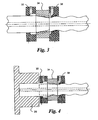
- the distal end 32 of the workpiece extends into manifold 30 ( FIG. 2 ) of the cathodic tool 26, which serves as the electrolyte outlet manifold, and is supported along its length by one or more suitable supports, such as support 31, to prevent it from sagging.
- the machining of a progressive cavity pump rotor, using the apparatus of FIG. 1 may be carried out using a voltage in the range from about 10 to 25 volts DC, typically 18 volts.
- the feed rate of the workpiece should be in the range of about 0.2 to 1 inch per minute, depending on the cross sectional area to be removed. A typical feed rate is 0.75 inch per minute.
- the current is approximately 10,000 Amperes for each cubic inch of material removed per minute.
- the capability of the power supply may vary from application to application as required.
- a typical electrolyte is a water solution of sodium chloride (NaCl) at a concentration of 1.1 pounds per gallon of water. In practice, the concentration may be varied from about 0.5 pounds per gallon to about 2.5 pounds per gallon of water.
- An alternate electrolyte composition can be a water solution of sodium nitrate (NaNO 3 ) at a concentration in the range from about 0.5 to about 3.0 pounds per gallon of water. Mixtures of NaNO 3 and NaCl may also be used, as can many other suitable electrolytes.
- the electrolyte outlet manifold 30 is attached to a tapered cathodic electrode 34, and is used to expel the electrolyte for the ECM process.
- the manifold 30 locates and centers the workpiece as it enters the cathodic tool, and provides a seal around the initial, unmachined, circular, cylindrical contour of the workpiece, while receiving electrolyte flowing out of the cathodic electrode.
- a blank 36 having an external shape corresponding to that of the final machined rotor, is secured to the distal, or leading, end 32 of the workpiece 22.
- This blank extends through the cathodic tool 34, and through an electrolyte entry manifold 38, attached to the end of the cathodic tool on the side opposite from manifold 30.
- the blank 36 passes through suitably shaped seals in the exit manifold 38, and prevents flow of electrolyte past the seals as the distal end 32 of the workpiece approaches the seals.
- the blank may be made of a suitable synthetic resin such as the acetal resin known by the trademark DELRIN, or PTFE.
- the blank may be a metal such as Niobium that has a breakdown potential far in excess of the breakdown potential for ordinary workpieces during the ECM process.
- the electrolyte inlet manifold 38 is supplied with electrolyte from an electrolyte pump 40, shown in FIG. 1 , which receives electrolyte from a holding tank 42. Electrolyte is returned to the holding tank 42 from the electrolyte outlet manifold 30 through a pressure control valve 50.
- the cathodic tool 24 has a generally round entry opening 44 corresponding to the shape of the workpiece, and its interior gradually transforms to a four-lobed exit opening 46, corresponding to the desired configuration of the rotor 47, as shown in FIG. 7 .
- the profile of the exit opening 46 of the cathodic tool, as shown in FIG. 8 is slightly larger than the desired cross section of the workpiece.
- the interior surface of the cathodic tool has a twisted configuration as shown in FIG. 10 .
- the shape of the interior of the cathodic tool can have the straight through configuration shown in FIG. 9 , where the interior surface 48 can be generated by straight lines intersecting a single point on a central axis .
- the cathodic tool is constructed from a conductive material such as a material consisting of 70% tungsten and 30% copper.
- the cathodic tool acts as a trepan tool used in milling and drilling operations except that no mechanical cutting action is required, and the shape of the product can have a complex contour, whereas only circular shapes can be produced with conventional trepan machining.
- the electrolyte inlet manifold 38 which is connected to the electrolyte pumping system, is required to seal on the finish-machined profile of the workpiece.
- the seals in manifold 38 are shaped to match the helical lobes of the product. As shown in FIG. 2A , these seals are provided with grooves, each having a cup type lip 51, in which a compliant spring 53 is installed, to assist the internal pressure of the electrolyte in forcing contact between the seals and the profiled surface of the finished workpiece.
- Pressure and temperature of the electrolyte in the electrolyte recirculation path may be controlled by temperature and pressure transducers, pressure regulators and heat exchangers (not shown).
- FIG. 1 illustrates supports 52 on the machine frame, which prevent the stress on the manifolds from becoming too large.
- the supports 52 carry the weight of the distal portion of the workpiece.
- These supports may either move with the workpiece, or may be made of a suitable material to avoid damage to the finish-machined profile of the workpiece.
- steel supports having non-metallic wear plates for contact with the workpiece, are used. After completion of the electrochemical machining operation, the machined workpiece is backed out of the cathode assembly.
- electrolyte is caused to flow in the same direction in which the workpiece travels in the machining operation.
- electrolyte is pumped manifold 30, flows in the distal direction between the workpiece and the cathodic tool, and out through the manifold 38 for recirculation.
- another alternative is to allow the electrolyte to flow through the cathodic tool and exit without passing through an exit manifold. This may be required in cases where the profile of the finish machined workpiece has relatively sharp corners, or is otherwise shaped so that it does not provide a good sealing surface that can be sealed by seals in an exit manifold.
- a gravity drain system would then be required to return the electrolyte to the pumping system.
- the flow rates should be high enough to create a back pressure to force flow across the entire area, as shown in FIG. 7 , between the inside surface 46 of the cathode, and the outside profile of the workpiece.
- Heat is generated because of the high electric current in the apparatus.
- the heat must be removed to maintain a stable system.
- a separate holding tank 54 and pump 56 are used to supply cool water to remove heat. Water is also pumped through the power supply 24 and the conductive cables that connect the power supply to the cathodic tool and the workpiece. Water is also used to cool the part holder 29, shown in FIG. 4 .
- the holding tank 54 is maintained at a fixed temperature by using a temperature control system (not shown) and a heat exchanger (not shown) that isolates the temperature control system from the electrolyte.
- the ECM process is one that uses an electrical potential to break down the water (H 2 O) into a hydroxide (OH - ) ion that joins with a metal ion to form a metal hydroxide such as Fe(OH) 2 .
- Hydrogen gas is formed in the process, and must be removed from the machining system to prevent gas bubbles from forming an electrically insulating obstruction to the process. Controlling the pressure of the electrolyte entering through the electrolyte inlet manifold, and the pressure at the electrolyte outlet manifold, allows for control of both the electrolyte flow rate, and the pressure within the ECM cell, to limit the formation of gas. Higher pressure in the outlet manifold also helps force electrolyte around contours that would otherwise cause cavitations in the electrolyte.
- the apparatus is operated by a controller 58, which performs multiple functions.
- the controller programs the translation and rotation of the workpiece to produce the helical shapes required in the case of a rotor having helical lobes for use in a progressive cavity fluid mechanism.
- the controller also maintains the proper voltage, taking into account the feed rate and the amount of material to be removed. It also controls proper timing of voltage changes.
- Other electrolyte functions such as the operation of pumps, pressure regulation, and temperature regulation, are also controlled by the controller.
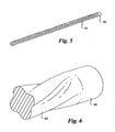
- the progress of a circular, cylindrical, workpiece through the cathodic electrode can be stopped at a point such that a short cylindrical portion is left at the proximal end of the workpiece, as shown in FIGs. 5 and 6 .
- the short cylindrical portion 60, and the part 62 having helical lobes remain joined as a unitary element.
- the cylindrical portion can be ground and plated, and used as a bearing journal for the rotor.
- the workpiece instead of pushing the workpiece through the cathodic tool, the workpiece may be pulled through the tool, by using a suitable attachment at the distal end of the workpiece. It may be desirable to pull rather than push the workpiece where the cross section of the workpiece is so weak that there is a risk of buckling.
Landscapes
- Engineering & Computer Science (AREA)
- Mechanical Engineering (AREA)
- Physics & Mathematics (AREA)
- Thermal Sciences (AREA)
- Chemical & Material Sciences (AREA)
- Chemical Kinetics & Catalysis (AREA)
- Electrochemistry (AREA)
- Electrical Discharge Machining, Electrochemical Machining, And Combined Machining (AREA)
- Particle Accelerators (AREA)
- Crystals, And After-Treatments Of Crystals (AREA)
Claims (9)
- Appareil pour l'usinage électrochimique d'une pièce de travail, ayant un grand rapport longueur sur diamètre, en un produit souhaité, caractérisé en ce que l'appareil comprend :un outil cathodique ayant un passage traversant pour recevoir une pièce de travail, le passage ayant une ouverture d'entrée et une ouverture de sortie, l'ouverture d'entrée correspondant en forme à, et étant légèrement plus grande que, la section transversale de la pièce de travail, et l'ouverture de sortie correspondant en forme à, et étant légèrement plus grande que, la section transversale du produit fini souhaité, la forme en section transversale du passage traversant ayant une transition progressive allant de la forme de l'ouverture d'entrée à la forme de l'ouverture de sortie, le long de la longueur du passage traversant ;un collecteur relié à l'outil cathodique adjacent à l'une desdites ouvertures d'entrée et de sortie pour diriger de l'électrolyte à travers ledit passage traversant de l'outil cathodique, autour d'une pièce de travail se déplaçant à travers ledit passage traversant ;un mécanisme d'entraînement pour déplacer la pièce de travail à travers ledit passage traversant de l'outil cathodique et ledit collecteur ;des supports pour maintenir la pièce de travail lorsqu'elle se déplace à travers l'outil cathodique ; etune alimentation en énergie électrique reliée à l'outil cathodique et pouvant être reliée à la pièce de travail.
- Appareil selon la revendication 1, dans lequel ledit collecteur comprend un premier collecteur relié à l'outil cathodique adjacent à l'une desdites ouvertures d'entrée et de sortie de ce dernier, et un second collecteur relié à l'outil cathodique adjacent à l'autre desdites ouvertures d'entrée et de sortie de ce dernier, le collecteur adjacent à l'ouverture de sortie présentant un joint se conformant à la forme en section transversale souhaitée du produit fini, dans lequel ledit second collecteur reçoit de l'électrolyte avant que ledit électrolyte ne passe à travers ledit passage traversant de l'outil cathodique autour d'une pièce de travail en son sein, et comportant un chemin pour recycler l'électrolyte en provenance dudit premier collecteur à destination dudit second collecteur.
- Appareil selon la revendication 1, dans lequel l'ouverture d'entrée dudit passage traversant de l'outil cathodique est circulaire, l'ouverture de sortie de l'outil cathodique présente une forme en section transversale à lobes, et le passage traversant de l'outil cathodique comporte des lobes qui augmentent progressivement en taille, en se poursuivant dans le sens allant de ladite ouverture d'entrée vers ladite ouverture de sortie.
- Appareil selon la revendication 1, dans lequel le mécanisme de commande comprend un mécanisme pour faire tourner la pièce de travail autour d'un axe le long de sa longueur lorsque la pièce de travail se déplace à travers ledit passage de l'outil cathodique, l'ouverture d'entrée dudit passage traversant de l'outil cathodique est circulaire, l'ouverture de sortie de l'outil cathodique présente une forme en section transversale à lobes, et le passage traversant de l'outil cathodique comporte des lobes qui augmentent ensemble progressivement en taille, et qui s'enroulent autour dudit axe, en se poursuivant dans le sens allant de ladite ouverture d'entrée vers ladite ouverture de sortie.
- Procédé d'usinage électrochimique d'une pièce de travail, ayant un grand rapport longueur sur diamètre, en un produit fini, caractérisé en ce que le procédé comprend les étapes consistant à :entraîner la pièce de travail à travers un outil cathodique ayant un passage traversant pour recevoir la pièce de travail, le passage ayant une ouverture d'entrée et une ouverture de sortie, l'ouverture d'entrée correspondant en forme à, et étant légèrement plus grande que, la section transversale de la pièce de travail, et l'ouverture de sortie correspondant en forme à, et étant légèrement plus grande que, la section transversale du produit fini, la forme en section transversale du passage traversant ayant une transition progressive allant de la forme de l'ouverture d'entrée à la forme de l'ouverture de sortie, le long de la longueur du passage traversant ;fournir de l'électrolyte dans ledit passage traversant de l'outil cathodique, autour de la pièce de travail lorsque la pièce de travail se déplace à travers ledit passage traversant ;établir un courant électrique à travers ledit électrolyte, entre la pièce de travail et l'outil cathodique, lorsque la pièce de travail est entraînée par l'outil cathodique.
- Procédé selon la revendication 5, dans lequel l'électrolyte est amené à s'écouler à travers ledit passage traversant, à l'intérieur d'un espace entre une paroi intérieure de l'outil cathodique et la pièce de travail.
- Procédé selon la revendication 5, dans lequel l'ouverture d'entrée dudit passage traversant de l'outil cathodique est circulaire, l'ouverture de sortie de l'outil cathodique présente une forme en section transversale à lobes, et le passage traversant de l'outil cathodique comporte des lobes qui augmentent progressivement en taille, en se poursuivant dans le sens allant de ladite ouverture d'entrée vers ladite ouverture de sortie.
- Procédé selon la revendication 5, dans lequel la pièce de travail est tournée autour d'un axe le long de sa longueur lorsque la pièce de travail est déplacée à travers ledit passage de l'outil cathodique, dans lequel l'ouverture d'entrée dudit passage traversant de l'outil cathodique est circulaire, l'ouverture de sortie de l'outil cathodique présente une forme en section transversale à lobes, et le passage traversant de l'outil cathodique comporte des lobes qui augmentent ensemble progressivement en taille, et qui s'enroulent autour dudit axe, en se poursuivant dans le sens allant de ladite ouverture d'entrée vers ladite ouverture de sortie.
- Procédé selon la revendication 5, dans lequel la pièce de travail présente initialement une section transversale circulaire, cylindrique, et dans lequel le mouvement de la pièce de travail est arrêté avant que la pièce de travail entière ne soit entraînée dans l'outil cathodique, de sorte qu'une partie circulaire, cylindrique de la pièce de travail reste en tant que partie du produit, pour une utilisation en tant que tourillon de palier.
Applications Claiming Priority (4)
| Application Number | Priority Date | Filing Date | Title |
|---|---|---|---|
| US51004103P | 2003-10-09 | 2003-10-09 | |
| US510041P | 2003-10-09 | ||
| US10/886,953 US7479214B2 (en) | 2003-10-09 | 2004-07-08 | ECM trepan of bars |
| US886953 | 2004-07-08 |
Publications (3)
| Publication Number | Publication Date |
|---|---|
| EP1522367A2 EP1522367A2 (fr) | 2005-04-13 |
| EP1522367A3 EP1522367A3 (fr) | 2006-07-05 |
| EP1522367B1 true EP1522367B1 (fr) | 2009-06-03 |
Family
ID=34316852
Family Applications (1)
| Application Number | Title | Priority Date | Filing Date |
|---|---|---|---|
| EP04021415A Expired - Lifetime EP1522367B1 (fr) | 2003-10-09 | 2004-09-09 | Usinage par électrochimie de barres |
Country Status (4)
| Country | Link |
|---|---|
| US (1) | US7479214B2 (fr) |
| EP (1) | EP1522367B1 (fr) |
| AT (1) | ATE432788T1 (fr) |
| DE (1) | DE602004021330D1 (fr) |
Families Citing this family (5)
| Publication number | Priority date | Publication date | Assignee | Title |
|---|---|---|---|---|
| CN102179584B (zh) * | 2011-06-02 | 2012-11-14 | 重庆望江工业有限公司 | 多头圆弧螺旋杆件的电解加工装置 |
| CN102345147B (zh) * | 2011-10-27 | 2013-09-18 | 宝钢工程技术集团有限公司 | 轧辊表面旋转支撑镀铬装置 |
| CN103302367B (zh) * | 2013-03-19 | 2016-06-08 | 北京航星机器制造有限公司 | 一种外螺旋结构电火花成型加工方法 |
| US9976227B2 (en) * | 2014-05-15 | 2018-05-22 | Baker Hughes, A Ge Company, Llc | Electrochemical machining method for rotors or stators for moineau pumps |
| CN109909566B (zh) * | 2019-03-18 | 2020-04-24 | 南京航空航天大学 | 低温环境套料电解加工阴极系统及方法 |
Family Cites Families (5)
| Publication number | Priority date | Publication date | Assignee | Title |
|---|---|---|---|---|
| US3499830A (en) * | 1967-11-20 | 1970-03-10 | Cincinnati Milling Machine Co | Apparatus for electrochemically forming and finishing gears |
| US3723268A (en) * | 1967-12-21 | 1973-03-27 | Prod Eng Res Ass | Electrochemical machining |
| US3591473A (en) * | 1968-04-08 | 1971-07-06 | Cincinnati Milacron Inc The | Method and apparatus for electrochemically machining rotating parts |
| US6387242B1 (en) * | 1999-08-16 | 2002-05-14 | General Electric Company | Method and tool for electrochemical machining |
| US6413407B1 (en) * | 2000-11-27 | 2002-07-02 | Lehr Precision, Inc. | Fluted electrochemical machining |
-
2004
- 2004-07-08 US US10/886,953 patent/US7479214B2/en not_active Expired - Lifetime
- 2004-09-09 AT AT04021415T patent/ATE432788T1/de not_active IP Right Cessation
- 2004-09-09 DE DE602004021330T patent/DE602004021330D1/de not_active Expired - Fee Related
- 2004-09-09 EP EP04021415A patent/EP1522367B1/fr not_active Expired - Lifetime
Also Published As
| Publication number | Publication date |
|---|---|
| EP1522367A2 (fr) | 2005-04-13 |
| US20050077189A1 (en) | 2005-04-14 |
| EP1522367A3 (fr) | 2006-07-05 |
| ATE432788T1 (de) | 2009-06-15 |
| HK1077036A1 (en) | 2006-02-03 |
| DE602004021330D1 (de) | 2009-07-16 |
| US7479214B2 (en) | 2009-01-20 |
Similar Documents
| Publication | Publication Date | Title |
|---|---|---|
| US7192260B2 (en) | Progressive cavity pump/motor stator, and apparatus and method to manufacture same by electrochemical machining | |
| EP1932611B1 (fr) | Ensemble à axe adaptatif pour l'usinage par électroérosion sur un outil d'usinage par CNC | |
| JP2011067938A (ja) | 電解加工に関するシステム及び装置 | |
| JP2011067939A (ja) | 電解加工に関する方法、システム及び装置 | |
| US5685971A (en) | Apparatus and method for forming a variable diameter hole in a conductive workpiece | |
| WO2002042030A2 (fr) | Usinage electrochimique a cannelures | |
| EP1522367B1 (fr) | Usinage par électrochimie de barres | |
| CN115780932B (zh) | 一种电解-磨削精密扩孔加工装置 | |
| HK1077036B (en) | Ecm trepan of bars | |
| Jain et al. | State-of-art-review of electrochemical honing of internal cylinders and gears | |
| CA2504529C (fr) | Pompe a cavite progressive/stator de moteur, et appareil et methode de fabrication par usinage electrochimique | |
| CN116372291B (zh) | 一种深小孔内壁微结构的电解加工装置及方法 | |
| US4650549A (en) | Method for electroplating helical rotors | |
| US20190270154A1 (en) | Two-fluid device for electroerosion | |
| RU2663789C1 (ru) | Электродный блок для электрохимической обработки винтового зубчатого профиля в отверстии трубчатой заготовки | |
| CN213318167U (zh) | 一种立式数控电解磨削镗孔装置 | |
| RU2578895C2 (ru) | Установка для электрохимической обработки винтового зубчатого профиля внутренней поверхности в отверстии трубчатой заготовки | |
| RU2774193C1 (ru) | Электродный блок для электрохимической обработки винтового зубчатого профиля в отверстии трубчатой заготовки | |
| Mander et al. | A novel gap flushing insert for sink electrical discharge machining | |
| Singh et al. | Developments in electro-chemical honing (ECH): a review on experimental investigation of precision finishing of mechanical parts | |
| HK1077037B (en) | Progressive cavity pump / motor stator, and apparatus and method to manufacture same by electrochemical machining | |
| CN101332527A (zh) | 电腐蚀加工工具和方法 | |
| CN116900428B (zh) | 大长径比全金属转子外螺旋复杂曲面电解加工装置及方法 | |
| RU2774195C1 (ru) | Электродный блок для электрохимической обработки винтового зубчатого профиля в отверстии трубчатой заготовки | |
| CN121061262A (zh) | 一种深孔大直径型腔成形电解夹具及方法 |
Legal Events
| Date | Code | Title | Description |
|---|---|---|---|
| PUAI | Public reference made under article 153(3) epc to a published international application that has entered the european phase |
Free format text: ORIGINAL CODE: 0009012 |
|
| AK | Designated contracting states |
Kind code of ref document: A2 Designated state(s): AT BE BG CH CY CZ DE DK EE ES FI FR GB GR HU IE IT LI LU MC NL PL PT RO SE SI SK TR |
|
| AX | Request for extension of the european patent |
Extension state: AL HR LT LV MK |
|
| REG | Reference to a national code |
Ref country code: HK Ref legal event code: DE Ref document number: 1077036 Country of ref document: HK |
|
| PUAL | Search report despatched |
Free format text: ORIGINAL CODE: 0009013 |
|
| AK | Designated contracting states |
Kind code of ref document: A3 Designated state(s): AT BE BG CH CY CZ DE DK EE ES FI FR GB GR HU IE IT LI LU MC NL PL PT RO SE SI SK TR |
|
| AX | Request for extension of the european patent |
Extension state: AL HR LT LV MK |
|
| RIC1 | Information provided on ipc code assigned before grant |
Ipc: C25F 3/00 20060101ALI20060526BHEP Ipc: B23H 3/00 20060101ALI20060526BHEP Ipc: B23H 9/00 20060101AFI20050203BHEP |
|
| 17P | Request for examination filed |
Effective date: 20070104 |
|
| AKX | Designation fees paid |
Designated state(s): AT BE BG CH CY CZ DE DK EE ES FI FR GB GR HU IE IT LI LU MC NL PL PT RO SE SI SK TR |
|
| GRAP | Despatch of communication of intention to grant a patent |
Free format text: ORIGINAL CODE: EPIDOSNIGR1 |
|
| GRAS | Grant fee paid |
Free format text: ORIGINAL CODE: EPIDOSNIGR3 |
|
| GRAA | (expected) grant |
Free format text: ORIGINAL CODE: 0009210 |
|
| AK | Designated contracting states |
Kind code of ref document: B1 Designated state(s): AT BE BG CH CY CZ DE DK EE ES FI FR GB GR HU IE IT LI LU MC NL PL PT RO SE SI SK TR |
|
| REG | Reference to a national code |
Ref country code: GB Ref legal event code: FG4D |
|
| REG | Reference to a national code |
Ref country code: CH Ref legal event code: EP |
|
| REG | Reference to a national code |
Ref country code: IE Ref legal event code: FG4D |
|
| REF | Corresponds to: |
Ref document number: 602004021330 Country of ref document: DE Date of ref document: 20090716 Kind code of ref document: P |
|
| PG25 | Lapsed in a contracting state [announced via postgrant information from national office to epo] |
Ref country code: AT Free format text: LAPSE BECAUSE OF FAILURE TO SUBMIT A TRANSLATION OF THE DESCRIPTION OR TO PAY THE FEE WITHIN THE PRESCRIBED TIME-LIMIT Effective date: 20090603 Ref country code: FI Free format text: LAPSE BECAUSE OF FAILURE TO SUBMIT A TRANSLATION OF THE DESCRIPTION OR TO PAY THE FEE WITHIN THE PRESCRIBED TIME-LIMIT Effective date: 20090603 |
|
| NLV1 | Nl: lapsed or annulled due to failure to fulfill the requirements of art. 29p and 29m of the patents act | ||
| PG25 | Lapsed in a contracting state [announced via postgrant information from national office to epo] |
Ref country code: NL Free format text: LAPSE BECAUSE OF FAILURE TO SUBMIT A TRANSLATION OF THE DESCRIPTION OR TO PAY THE FEE WITHIN THE PRESCRIBED TIME-LIMIT Effective date: 20090603 Ref country code: PL Free format text: LAPSE BECAUSE OF FAILURE TO SUBMIT A TRANSLATION OF THE DESCRIPTION OR TO PAY THE FEE WITHIN THE PRESCRIBED TIME-LIMIT Effective date: 20090603 Ref country code: SI Free format text: LAPSE BECAUSE OF FAILURE TO SUBMIT A TRANSLATION OF THE DESCRIPTION OR TO PAY THE FEE WITHIN THE PRESCRIBED TIME-LIMIT Effective date: 20090603 Ref country code: SE Free format text: LAPSE BECAUSE OF FAILURE TO SUBMIT A TRANSLATION OF THE DESCRIPTION OR TO PAY THE FEE WITHIN THE PRESCRIBED TIME-LIMIT Effective date: 20090903 |
|
| REG | Reference to a national code |
Ref country code: HK Ref legal event code: GR Ref document number: 1077036 Country of ref document: HK |
|
| PG25 | Lapsed in a contracting state [announced via postgrant information from national office to epo] |
Ref country code: RO Free format text: LAPSE BECAUSE OF FAILURE TO SUBMIT A TRANSLATION OF THE DESCRIPTION OR TO PAY THE FEE WITHIN THE PRESCRIBED TIME-LIMIT Effective date: 20090603 Ref country code: CZ Free format text: LAPSE BECAUSE OF FAILURE TO SUBMIT A TRANSLATION OF THE DESCRIPTION OR TO PAY THE FEE WITHIN THE PRESCRIBED TIME-LIMIT Effective date: 20090603 Ref country code: EE Free format text: LAPSE BECAUSE OF FAILURE TO SUBMIT A TRANSLATION OF THE DESCRIPTION OR TO PAY THE FEE WITHIN THE PRESCRIBED TIME-LIMIT Effective date: 20090603 Ref country code: ES Free format text: LAPSE BECAUSE OF FAILURE TO SUBMIT A TRANSLATION OF THE DESCRIPTION OR TO PAY THE FEE WITHIN THE PRESCRIBED TIME-LIMIT Effective date: 20090914 |
|
| PG25 | Lapsed in a contracting state [announced via postgrant information from national office to epo] |
Ref country code: BE Free format text: LAPSE BECAUSE OF FAILURE TO SUBMIT A TRANSLATION OF THE DESCRIPTION OR TO PAY THE FEE WITHIN THE PRESCRIBED TIME-LIMIT Effective date: 20090603 Ref country code: SK Free format text: LAPSE BECAUSE OF FAILURE TO SUBMIT A TRANSLATION OF THE DESCRIPTION OR TO PAY THE FEE WITHIN THE PRESCRIBED TIME-LIMIT Effective date: 20090603 |
|
| PG25 | Lapsed in a contracting state [announced via postgrant information from national office to epo] |
Ref country code: BG Free format text: LAPSE BECAUSE OF FAILURE TO SUBMIT A TRANSLATION OF THE DESCRIPTION OR TO PAY THE FEE WITHIN THE PRESCRIBED TIME-LIMIT Effective date: 20090903 Ref country code: PT Free format text: LAPSE BECAUSE OF FAILURE TO SUBMIT A TRANSLATION OF THE DESCRIPTION OR TO PAY THE FEE WITHIN THE PRESCRIBED TIME-LIMIT Effective date: 20091003 |
|
| PLBE | No opposition filed within time limit |
Free format text: ORIGINAL CODE: 0009261 |
|
| STAA | Information on the status of an ep patent application or granted ep patent |
Free format text: STATUS: NO OPPOSITION FILED WITHIN TIME LIMIT |
|
| PG25 | Lapsed in a contracting state [announced via postgrant information from national office to epo] |
Ref country code: DK Free format text: LAPSE BECAUSE OF FAILURE TO SUBMIT A TRANSLATION OF THE DESCRIPTION OR TO PAY THE FEE WITHIN THE PRESCRIBED TIME-LIMIT Effective date: 20090603 Ref country code: MC Free format text: LAPSE BECAUSE OF NON-PAYMENT OF DUE FEES Effective date: 20090930 |
|
| REG | Reference to a national code |
Ref country code: CH Ref legal event code: PL |
|
| 26N | No opposition filed |
Effective date: 20100304 |
|
| GBPC | Gb: european patent ceased through non-payment of renewal fee |
Effective date: 20090909 |
|
| REG | Reference to a national code |
Ref country code: FR Ref legal event code: ST Effective date: 20100531 |
|
| PG25 | Lapsed in a contracting state [announced via postgrant information from national office to epo] |
Ref country code: IE Free format text: LAPSE BECAUSE OF NON-PAYMENT OF DUE FEES Effective date: 20090909 Ref country code: FR Free format text: LAPSE BECAUSE OF NON-PAYMENT OF DUE FEES Effective date: 20090930 Ref country code: DE Free format text: LAPSE BECAUSE OF NON-PAYMENT OF DUE FEES Effective date: 20100401 |
|
| PG25 | Lapsed in a contracting state [announced via postgrant information from national office to epo] |
Ref country code: CH Free format text: LAPSE BECAUSE OF NON-PAYMENT OF DUE FEES Effective date: 20090930 Ref country code: LI Free format text: LAPSE BECAUSE OF NON-PAYMENT OF DUE FEES Effective date: 20090930 Ref country code: GR Free format text: LAPSE BECAUSE OF FAILURE TO SUBMIT A TRANSLATION OF THE DESCRIPTION OR TO PAY THE FEE WITHIN THE PRESCRIBED TIME-LIMIT Effective date: 20090904 |
|
| PG25 | Lapsed in a contracting state [announced via postgrant information from national office to epo] |
Ref country code: GB Free format text: LAPSE BECAUSE OF NON-PAYMENT OF DUE FEES Effective date: 20090909 |
|
| PG25 | Lapsed in a contracting state [announced via postgrant information from national office to epo] |
Ref country code: IT Free format text: LAPSE BECAUSE OF FAILURE TO SUBMIT A TRANSLATION OF THE DESCRIPTION OR TO PAY THE FEE WITHIN THE PRESCRIBED TIME-LIMIT Effective date: 20090603 |
|
| PG25 | Lapsed in a contracting state [announced via postgrant information from national office to epo] |
Ref country code: LU Free format text: LAPSE BECAUSE OF NON-PAYMENT OF DUE FEES Effective date: 20090909 |
|
| PG25 | Lapsed in a contracting state [announced via postgrant information from national office to epo] |
Ref country code: HU Free format text: LAPSE BECAUSE OF FAILURE TO SUBMIT A TRANSLATION OF THE DESCRIPTION OR TO PAY THE FEE WITHIN THE PRESCRIBED TIME-LIMIT Effective date: 20091204 |
|
| PG25 | Lapsed in a contracting state [announced via postgrant information from national office to epo] |
Ref country code: TR Free format text: LAPSE BECAUSE OF FAILURE TO SUBMIT A TRANSLATION OF THE DESCRIPTION OR TO PAY THE FEE WITHIN THE PRESCRIBED TIME-LIMIT Effective date: 20090603 |
|
| PG25 | Lapsed in a contracting state [announced via postgrant information from national office to epo] |
Ref country code: CY Free format text: LAPSE BECAUSE OF FAILURE TO SUBMIT A TRANSLATION OF THE DESCRIPTION OR TO PAY THE FEE WITHIN THE PRESCRIBED TIME-LIMIT Effective date: 20090603 |