EP1522361A1 - Präzisionsbearbeitungsverfahren für innendurchmesser von löchern in kurbelwellen und maschine dafür - Google Patents
Präzisionsbearbeitungsverfahren für innendurchmesser von löchern in kurbelwellen und maschine dafür Download PDFInfo
- Publication number
- EP1522361A1 EP1522361A1 EP02783097A EP02783097A EP1522361A1 EP 1522361 A1 EP1522361 A1 EP 1522361A1 EP 02783097 A EP02783097 A EP 02783097A EP 02783097 A EP02783097 A EP 02783097A EP 1522361 A1 EP1522361 A1 EP 1522361A1
- Authority
- EP
- European Patent Office
- Prior art keywords
- axis
- crankshaft
- milling
- flange
- along
- Prior art date
- Legal status (The legal status is an assumption and is not a legal conclusion. Google has not performed a legal analysis and makes no representation as to the accuracy of the status listed.)
- Withdrawn
Links
Images

Classifications
-
- B—PERFORMING OPERATIONS; TRANSPORTING
- B23—MACHINE TOOLS; METAL-WORKING NOT OTHERWISE PROVIDED FOR
- B23C—MILLING
- B23C3/00—Milling particular work; Special milling operations; Machines therefor
- B23C3/02—Milling surfaces of revolution
-
- B—PERFORMING OPERATIONS; TRANSPORTING
- B23—MACHINE TOOLS; METAL-WORKING NOT OTHERWISE PROVIDED FOR
- B23C—MILLING
- B23C3/00—Milling particular work; Special milling operations; Machines therefor
- B23C3/06—Milling crankshafts
Definitions
- crankshaft The process of manufacturing a crankshaft requires many steps, high quality and precision.
- blind hole pilot boron
- the result is acceptable, but, from time to time, and for no apparent reason, the Quality Department of the car manufacturers detect anomalies in the precision finishing of these holes.
- crankshafts where the radial mass distribution is not compensated, for example a crankshaft for a six-cylinder engine.
- the diameter of the machined blind hole is measured, that it is compared to the dimension previously established for the diameter and, in case of difference between the two, that the corresponding compensation is ordered along the X or Y axis to the milling unit.
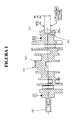
- crankshaft (C) Figure 1
- masses (p) decompensated radially and where a blind hole (e) has been made on the face of the flanges (f).
- the statistical requests for process capacity are from Ppk ⁇ 1.67.
- the measurement of the radial circular oscillation is carried out with the reading a comparator clock on the machined diameter, rotating the workpiece relative to the reference axis.
- the solution is to make a milling, in which the relative movement between the workpiece and the cutter is circular.
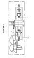
- the crankshaft (C) while the bit-tool (10) rotates (without moving) only for obtain the cutting speed (Figure 3a).
- the crankshaft rotates at a low speed, by example at 25 rpm.
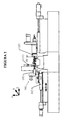
- crankshaft (C) is fixed by means of a lubricated bezel (1) with oil in the flange side support (f) and with a pin plate (2) which rotate the piece on the side of the post (g) (figures 1 and 2).
- the machining unit (m) consists of a spindle milling head horizontal (3) Z mounted on a cross slide Z-X, or Z-Y, or X-Y-Z with control digital (4), with direct position measuring devices ( Figure 2).
- the machining cycle is divided into two phases: a first half-finish with dive (according to the X or Y axis) (figure 3b) with the tool-milling cutter (10) around its axis (i) but without longitudinal movement and with tearing of turn (V), during which we leave reliefs for the final finish in diameter and a final finish (Figure 3c) the cutter (10) penetrating frontally following the Z axis.
- the tool (10) is cooled with a coolant.
- the diameter of the blind hole (e) is measured by a measuring device (9) in the next station, which compares the measurement obtained with previously established by ordering (12) the numerical control (4) of the unit machining (m) to correct the error that occurred due to the wear of the cutter (10), which allows a vintage compensation on the X or Y axis of the machining unit (m), which gives a great stability to the diameter obtained, at the same time as lengthening the service life of the tool (10).
Landscapes
- Engineering & Computer Science (AREA)
- Mechanical Engineering (AREA)
- Milling Processes (AREA)
- Turning (AREA)
- Shafts, Cranks, Connecting Bars, And Related Bearings (AREA)
Applications Claiming Priority (3)
| Application Number | Priority Date | Filing Date | Title |
|---|---|---|---|
| ES200201678P | 2002-07-12 | ||
| ES200201678A ES2198225B1 (es) | 2002-07-12 | 2002-07-12 | Proceso de mecanizado de precision para diametros interiores de orificios en cigueñales y maquina para dicho proceso. |
| PCT/ES2002/000494 WO2004007131A1 (es) | 2002-07-12 | 2002-10-18 | Proceso de mecanizado de precisión para diámetros interiores de orificios en cigüeñales y máquina para dicho proceso |
Publications (1)
| Publication Number | Publication Date |
|---|---|
| EP1522361A1 true EP1522361A1 (de) | 2005-04-13 |
Family
ID=30011370
Family Applications (1)
| Application Number | Title | Priority Date | Filing Date |
|---|---|---|---|
| EP02783097A Withdrawn EP1522361A1 (de) | 2002-07-12 | 2002-10-18 | Präzisionsbearbeitungsverfahren für innendurchmesser von löchern in kurbelwellen und maschine dafür |
Country Status (4)
| Country | Link |
|---|---|
| EP (1) | EP1522361A1 (de) |
| AU (1) | AU2002346852A1 (de) |
| ES (1) | ES2198225B1 (de) |
| WO (1) | WO2004007131A1 (de) |
Cited By (2)
| Publication number | Priority date | Publication date | Assignee | Title |
|---|---|---|---|---|
| CN102091936A (zh) * | 2011-01-24 | 2011-06-15 | 青岛淄柴博洋柴油机股份有限公司 | 曲轴油孔的加工方法 |
| CN107052396A (zh) * | 2017-04-14 | 2017-08-18 | 江苏万力机械股份有限公司 | 在中频淬火曲轴中油孔角度的设计方法 |
Families Citing this family (2)
| Publication number | Priority date | Publication date | Assignee | Title |
|---|---|---|---|---|
| RU2743712C2 (ru) | 2016-06-20 | 2021-02-24 | Этксе-Тар, С.А. | Станок для механической обработки заготовок |
| CN106238774B (zh) * | 2016-08-27 | 2018-03-06 | 余静远 | 一种铣床 |
Family Cites Families (4)
| Publication number | Priority date | Publication date | Assignee | Title |
|---|---|---|---|---|
| GB550086A (en) * | 1941-08-30 | 1942-12-22 | Emyr Pryce Edwards Thomas | Means for centering or otherwise operating upon the ends of cranks and other shafts and like work |
| JPS614608A (ja) * | 1984-06-14 | 1986-01-10 | Yamazaki Mazak Corp | 数値制御旋盤における穴加工制御方法 |
| ATE44251T1 (de) * | 1986-04-04 | 1989-07-15 | Gfm Fertigungstechnik | Endenbearbeitungsmaschine. |
| JPH0661650B2 (ja) * | 1987-10-12 | 1994-08-17 | 日立精機株式会社 | 2軸制御装置を備えた複合加工機 |
-
2002
- 2002-07-12 ES ES200201678A patent/ES2198225B1/es not_active Expired - Fee Related
- 2002-10-18 AU AU2002346852A patent/AU2002346852A1/en not_active Abandoned
- 2002-10-18 WO PCT/ES2002/000494 patent/WO2004007131A1/es not_active Ceased
- 2002-10-18 EP EP02783097A patent/EP1522361A1/de not_active Withdrawn
Non-Patent Citations (1)
| Title |
|---|
| See references of WO2004007131A1 * |
Cited By (3)
| Publication number | Priority date | Publication date | Assignee | Title |
|---|---|---|---|---|
| CN102091936A (zh) * | 2011-01-24 | 2011-06-15 | 青岛淄柴博洋柴油机股份有限公司 | 曲轴油孔的加工方法 |
| CN102091936B (zh) * | 2011-01-24 | 2013-12-11 | 青岛淄柴博洋柴油机股份有限公司 | 曲轴油孔的加工方法 |
| CN107052396A (zh) * | 2017-04-14 | 2017-08-18 | 江苏万力机械股份有限公司 | 在中频淬火曲轴中油孔角度的设计方法 |
Also Published As
| Publication number | Publication date |
|---|---|
| WO2004007131A1 (es) | 2004-01-22 |
| ES2198225A1 (es) | 2004-01-16 |
| ES2198225B1 (es) | 2005-04-01 |
| AU2002346852A1 (en) | 2004-02-02 |
Similar Documents
| Publication | Publication Date | Title |
|---|---|---|
| US8419323B2 (en) | Method for fine-machining crankshafts and machining center therefor | |
| EP0313644A1 (de) | Monotonische schneidevorrichtung. | |
| EP0806264B1 (de) | Werkzeugmaschine mit Exzenterspindel | |
| JPH07100269B2 (ja) | 工作機械における主軸回転駆動機構、前記主軸受台およびコラムガイドの軸受機構、バイトホルダ装着機構、フライス加工および中グリ加工の立て横両用変換装置、往復台摺動装置、テーブルの摺動機構、切削油自動回収処理装置、研削アタッチメント装置、該研削アタッチメント装置における砥石及び該砥石の接着方法、コラム及びコラムガイドの加工方法、横ゲタの加工方法 | |
| JP5307130B2 (ja) | 研削のときに回転する工作物を支持する方法、および動圧式の振れ止め | |
| EP1522361A1 (de) | Präzisionsbearbeitungsverfahren für innendurchmesser von löchern in kurbelwellen und maschine dafür | |
| US5056389A (en) | Portable open turning lathe | |
| CN115488403B (zh) | 一种机车驱动空心轴十字齿加工装置及方法 | |
| FR2481167A1 (fr) | Dispositif d'usinage de surfaces cylindriques | |
| JP5346651B2 (ja) | 内径研削工具の組立て方法 | |
| JP5399651B2 (ja) | 丸駒チップを用いる切削加工方法 | |
| EP0278898B1 (de) | Drehendes Futter für Schneidpost | |
| FR2480644A1 (fr) | Procede de percage de trous d'un diametre predetermine dans un ensemble de feuilles superposees comprenant au moins une feuille en materiau arme de fibres de verre ou de fibres de carbone, une feuille en acier et une feuille en titane | |
| US5531633A (en) | Method of machining a metal workpiece | |
| EP0811448B1 (de) | Regelvorrichtung der Position einer Bearbeitungsspindel | |
| EP2005110B1 (de) | Einrichtung zum zurücksetzen eines maschinenwerkzeugs mit anschlag | |
| US5171110A (en) | Apparatus and method for counterboring a pipe | |
| CN113926872B (zh) | 一种用于高强合金涡轮盘孔结构挤压强化的工艺 | |
| CN114951734B (zh) | 一种利用普车小孔加工器实现深小孔的加工方法 | |
| JP3291682B2 (ja) | 溝加工装置 | |
| CN121004299B (zh) | 一种钻镗复合刀具、深孔加工设备及深孔加工方法 | |
| O'Brien et al. | How to Run a Lathe: The Care and Operation of a Screw Cutting Lathe | |
| EP0169971A1 (de) | Universalschleifmaschine für Massenfertigung | |
| CN120941275A (zh) | 一种深孔内花键磨削专用内磨臂装置及加工方法 | |
| JPH02500349A (ja) | 研摩加工装置 |
Legal Events
| Date | Code | Title | Description |
|---|---|---|---|
| PUAI | Public reference made under article 153(3) epc to a published international application that has entered the european phase |
Free format text: ORIGINAL CODE: 0009012 |
|
| 17P | Request for examination filed |
Effective date: 20041022 |
|
| AK | Designated contracting states |
Kind code of ref document: A1 Designated state(s): AT BE BG CH CY CZ DE DK EE ES FI FR GB GR IE IT LI LU MC NL PT SE SK TR |
|
| AX | Request for extension of the european patent |
Extension state: AL LT LV MK RO SI |
|
| DAX | Request for extension of the european patent (deleted) | ||
| GRAP | Despatch of communication of intention to grant a patent |
Free format text: ORIGINAL CODE: EPIDOSNIGR1 |
|
| STAA | Information on the status of an ep patent application or granted ep patent |
Free format text: STATUS: THE APPLICATION HAS BEEN WITHDRAWN |
|
| 18W | Application withdrawn |
Effective date: 20071103 |