EP1522347B1 - Buse de distribution et procédé de mouillage d'une zone prédéterminée au moyen d'une telle buse - Google Patents
Buse de distribution et procédé de mouillage d'une zone prédéterminée au moyen d'une telle buse Download PDFInfo
- Publication number
- EP1522347B1 EP1522347B1 EP04405587A EP04405587A EP1522347B1 EP 1522347 B1 EP1522347 B1 EP 1522347B1 EP 04405587 A EP04405587 A EP 04405587A EP 04405587 A EP04405587 A EP 04405587A EP 1522347 B1 EP1522347 B1 EP 1522347B1
- Authority
- EP
- European Patent Office
- Prior art keywords
- nozzle
- spray
- central axis
- accordance
- distribution
- Prior art date
- Legal status (The legal status is an assumption and is not a legal conclusion. Google has not performed a legal analysis and makes no representation as to the accuracy of the status listed.)
- Expired - Lifetime
Links
- 238000000034 method Methods 0.000 title claims abstract description 12
- 238000009736 wetting Methods 0.000 title claims abstract description 7
- 239000007921 spray Substances 0.000 claims abstract description 85
- 239000012530 fluid Substances 0.000 claims abstract description 33
- 238000001816 cooling Methods 0.000 claims description 36
- 238000004519 manufacturing process Methods 0.000 claims 1
- 238000009792 diffusion process Methods 0.000 abstract 1
- 239000000498 cooling water Substances 0.000 description 7
- 230000000694 effects Effects 0.000 description 7
- 239000007788 liquid Substances 0.000 description 4
- 230000005855 radiation Effects 0.000 description 3
- 239000012809 cooling fluid Substances 0.000 description 2
- LFQSCWFLJHTTHZ-UHFFFAOYSA-N Ethanol Chemical compound CCO LFQSCWFLJHTTHZ-UHFFFAOYSA-N 0.000 description 1
- 230000015572 biosynthetic process Effects 0.000 description 1
- 239000003245 coal Substances 0.000 description 1
- 239000002826 coolant Substances 0.000 description 1
- 230000001419 dependent effect Effects 0.000 description 1
- 230000002262 irrigation Effects 0.000 description 1
- 238000003973 irrigation Methods 0.000 description 1
- 230000001105 regulatory effect Effects 0.000 description 1
- XLYOFNOQVPJJNP-UHFFFAOYSA-N water Substances O XLYOFNOQVPJJNP-UHFFFAOYSA-N 0.000 description 1
Images

Classifications
-
- F—MECHANICAL ENGINEERING; LIGHTING; HEATING; WEAPONS; BLASTING
- F28—HEAT EXCHANGE IN GENERAL
- F28F—DETAILS OF HEAT-EXCHANGE AND HEAT-TRANSFER APPARATUS, OF GENERAL APPLICATION
- F28F25/00—Component parts of trickle coolers
- F28F25/02—Component parts of trickle coolers for distributing, circulating, and accumulating liquid
- F28F25/06—Spray nozzles or spray pipes
-
- B—PERFORMING OPERATIONS; TRANSPORTING
- B05—SPRAYING OR ATOMISING IN GENERAL; APPLYING FLUENT MATERIALS TO SURFACES, IN GENERAL
- B05B—SPRAYING APPARATUS; ATOMISING APPARATUS; NOZZLES
- B05B1/00—Nozzles, spray heads or other outlets, with or without auxiliary devices such as valves, heating means
- B05B1/14—Nozzles, spray heads or other outlets, with or without auxiliary devices such as valves, heating means with multiple outlet openings; with strainers in or outside the outlet opening
- B05B1/18—Roses; Shower heads
- B05B1/185—Roses; Shower heads characterised by their outlet element; Mounting arrangements therefor
Definitions
- the invention relates to a distribution nozzle for distributing a fluid and a method for wetting a predeterminable area around the distribution nozzle according to the preamble of the independent claim of the respective category. Furthermore, the invention relates to a cooling tower with such a distribution nozzle, which is operable by a method according to the invention.
- Distribution nozzles are widely used as atomizing nozzles for atomizing a fluid in cooling devices, in particular in cooling towers.
- a cooling tower is to be understood as meaning any component of an open or closed cooling circuit which comprises an open or closed housing and has the distribution nozzles in the sense of this application for cooling the fluid.
- the fluid to be cooled such as the cooling water of a coal, gas or nuclear power plant or a corresponding cooling fluid of another technical device in which dissipates heat dissipated in operation, by one or more Verteildüsen for cooling in a second medium, For example, in air, atomized within the cooling tower, whereby the fluid can deliver a portion of its heat energy to the environment.
- the fluid does not necessarily have to be water. Any other liquid coolant, such as alcohol, or even a gas to be cooled may be considered as to be distributed or atomized in the distribution nozzle fluid.
- a distribution nozzle in the form of a spray nozzle which comprises a nozzle and a conical, provided with a plurality of openings diverging member, and a holding device, which holds the diverter at a distance from the nozzle and extends away therefrom.
- a liquid jet is directed from the nozzle to the conical diverging member, which diverges in the direction of flow of the liquid jet, wherein through the openings, which are arranged in concentric circles about a central axis of the diverging member, a rotationally symmetrical about the central axis field is generated by spray jets.
- a large cooling tower for example, a cooling tower of a power plant for generating electrical energy, may have several thousand such Verteldüsen, which may be distributed regularly over a floor area of several thousand square meters.
- the nozzles may be arranged on a rectangular or square grid formed by a system of supply lines and supplying the cooling water to the distribution nozzles. The cooling water is sprayed in the cooling tower, so that the cooling water can deliver a part of its heat energy to the cooling air in the cooling tower.
- the known from the prior art distribution nozzles such as the spray nozzles of DE 1 947 898 , are thereby preferably arranged in a relatively close distance from each other, so achieved by superposition of besprühbaren by individual spray nozzles surfaces, a more or less complete utilization of the surface to be sprayed in the cooling tower can be. Since the known spray nozzles, as explained above, provide a substantially rotationally symmetric spray pattern, arise either wholly or partially irrigation or poorly irrigated areas that provide either no or only a negligible contribution to the heat and mass transfer.
- the distributing nozzle according to the invention for distributing a fluid comprises a holding device for fixing a diverting element, and an inlet nozzle with a nozzle mouth for acting on the diverting element with the fluid, wherein the diverting element has a plurality of spray holes for generating spray jets from the fluid.
- the spray holes are configured and arranged with respect to a central axis of the diverging element such that, in the operating state, an emission angle of the spray jets varies in dependence on a polar angle measured about the central axis according to a predeterminable scheme.
- the emission angle of the spray jets in the distribution nozzle according to the invention varies with the polar angle about the central axis according to a predeterminable scheme, it is possible to completely uniformly wet surfaces with any delimitation around the distribution nozzle according to the invention with the fluid, for example with cooling water.
- the inlet nozzle the fluid, for example, the cooling water or other suitable liquid or gaseous cooling fluid, supplied by a supply line at a predetermined supply pressure, so that the fluid leaves the inlet nozzle through the nozzle mouth under a predetermined working pressure and the diverting element for Profdung of spray the fluid is applied.
- the sprays are through formed the plurality of spray holes of the diverging element, wherein the spray holes are configured and arranged with respect to the central axis of the diverging element, that the spray jets are imparted different radiation angles depending on the polar angle, so that due to the throwing parabolas of the spray jets an area with specifiable geometric boundary is wetted.
- the spray holes themselves which are arranged around the central axis of the diverting element, can be rounded in a manner known per se, round, elliptical, triangular, rectangular, in the form of an arc segment, or of any other suitable shape.
- one or more lateral wall boundaries of these openings diverge away from the inlet nozzle with respect to the central axis of the diverging element.
- the emission angle of the spray jets varies as a function of a distance to the central axis of the diverting element. That is, the spray holes are configured and arranged with respect to the central axis in the diverging element that the emission angle of the spray is both a function of the polar angle, as well as the distance of the spray hole from the central axis.
- the spray holes are configured and arranged with respect to the central axis of the diverging element such that the spray angle of the spray as a function of the polar angle and the distance from the central axis varies such that a substantially rectangular base around the Distribution nozzle is evenly wetted. That is, the spray holes are arranged and configured so that spray jets are distributed on different, for example, parabolic webs, depending on the polar angle and depending on the distance to the central axis of the diverging element on a substantially rectangular base.
- the spray holes are arranged in concentric circles with predeterminable radii at a distance around the central axis.
- the spray holes can also be arranged in other ways, for example on parallel elliptical paths, on rectilinear paths, such as on quadrangular or triangular tracks, or in particular also in any other suitable form in the diverter element.
- the diverting element itself preferably has a funnel-shaped expanding hollow shape with respect to the central axis and in a direction away from the nozzle mouth.
- the diverging element may, for example, have a concavely curved cross-section.
- the diverting element has a substantially triangular cross section and in a further preferred embodiment the diverting element has a convexly curved cross section.
- the cross section of the diverging element also have any other suitable shape.
- the method according to the invention for wetting a predeterminable area around a distribution nozzle with a fluid is carried out with a distribution nozzle comprising a holding device for fixing a diverting element and an inlet nozzle with a nozzle mouth for exposing the diverting element to the fluid, wherein the diverting element comprises a multiplicity of Spray holes for generating spray jets from the fluid and the spray holes are configured and arranged with respect to a central axis of the diverging element, that varies in the operating state, an emission angle of the spray in response to a measured about the central axis polar angle according to a predetermined scheme.
- the emission angle of the spray jets is adjusted so that a substantially rectangular area is wetted uniformly around the distribution nozzle.
- the invention also relates to a cooling device, in particular a cooling tower, with one of the distributing nozzle described in more detail above, which can be operated by a method according to the invention.
- Fig. 1 shows a schematic representation of a distribution nozzle according to the invention, which is referred to in the following entirety by the reference numeral 1.
- the distribution nozzle 1 for distributing a fluid 2 comprises a holding device 3 in which a diverting element 4 and an inlet nozzle 5 with a nozzle mouth 6 are fixed.
- the nozzle mouth 6 tapers to an outlet opening 61 in the direction of the diverting element 4, wherein the inlet nozzle 5 as shown below Discharge element 4 is placed in the holding device 3 so that the diverting element 4 to the formation of spray jets 8 through the outlet opening 61 with the fluid 2 can be acted upon.
- the illustration of the lower part of the inlet nozzle 5 has an inlet opening 51 for the fluid 2, so that the inlet nozzle 5 can be supplied via the inlet opening 51 from a supply line 9, which is connected to the distribution nozzle 1, with fluid 2.
- the fluid 2 in the supply line 9 is preferably under a predeterminable supply pressure, so that the fluid 2 leaves the inlet nozzle 5 through the nozzle mouth 6 at a predeterminable working pressure and thus applies the fluid 2 to the diverting element 4 for forming spray jets 8.
- the fluid 2 in the supply line 9 is preferably under a predeterminable supply pressure, so that the fluid 2 leaves the inlet nozzle 5 through the nozzle mouth 6 at a predeterminable working pressure and thus applies the fluid 2 to the diverting element 4 for forming spray jets 8.
- the diverting element 4 has a funnel-shaped, in a funnel shape with respect to the center axis M, in a direction widening away from the nozzle mouth 6 and having a concavely curved cross-section.
- the diverting element 4 To form the spray jets 8 and to form their emission angle ⁇ , the diverting element 4 a plurality of spray holes 7, which preferably, but not necessary, as shown schematically in Fig. 1, on concentric circles of radius R at a distance A from the central axis M are arranged.
- the spray holes 7 are designed as a substantially cylindrical openings with a circular cross section, wherein a central axis 71 of the bore 7 so in relation to a perpendicular to the central axis M imaginary plane is inclined at the Abstrahlkwinkel ⁇ that the corresponding spray jet 8 formed by the spray hole 7 leaves the spray hole 7 substantially at the same emission angle ⁇ .
- the angle ⁇ depends not only on the distance A of the spray hole 7 to the central axis M, but also from the polar angle ⁇ , under which the spray hole 7 is arranged with respect to the central axis M.
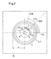
- Fig. 2 is a section along the line II - II according to FIG. 1 is shown schematically.
- the spray holes 7 are arranged in concentric circles with radius R at a distance A about the central axis M.
- the respective central axes 71, 72 of different spray bores 7 are inclined relative to a plane perpendicular to the central axis M at the angle of emission ⁇ such that the corresponding spray jet 8 formed by the spray hole 8 leaves the spray hole 7 substantially at the same emission angle ⁇ .
- the emission angle ⁇ of the spray jets 8 varies both as a function of the distance A to the central axis M, as well as in dependence on the polar angle ⁇ , under which the spray hole 7 is arranged with respect to the central axis M.
- the spray holes 7 are arranged so that a substantially square area 10 with fluid 2 is uniformly wetted by the distribution nozzle 1.
- two spray jets 81 and 82 are shown by way of example, emanating from two different spray holes 7 with different central axes 71 and 72.
- the two different ones Holes 7 with the respective center axes 71 and 72 are arranged at the same distance A under the same radius R, but at two different polar angles ⁇ 1 and ⁇ 2 with respect to the central axis M of the diverging element 4.
- the spray jet 81 has an emission angle ⁇ 1 and the spray jet 82 an emission angle ⁇ 2 , wherein in the present example the emission angle ⁇ 1 has a smaller value than the emission angle ⁇ 2 , since the spray jet 81 runs in the direction of a diagonal of the square-defined area 10 to be wetted, and thus has to bridge a greater distance than the spray jet 72, which therefore leaves the associated spray hole 7 at a larger radiation angle ⁇ 2 .
- the distribution nozzle according to the invention By using the distribution nozzle according to the invention, it is possible to completely uniformly irrigate areas and areas with any boundary, in particular rectangular or square areas, without irrigated or insufficiently irrigated area remaining or irrigating certain areas of two or more different distribution nozzles simultaneously and overlapping.
- the known disadvantages that arise in the known from the prior art distribution nozzles with rotationally symmetrical spray pattern completely overcome.
- a substantial improvement of the cooling is achieved in comparison to the known distribution nozzles, so that the cooling process can be much more efficient and energy-economical and therefore more cost-effective.
Landscapes
- Engineering & Computer Science (AREA)
- Physics & Mathematics (AREA)
- Thermal Sciences (AREA)
- Mechanical Engineering (AREA)
- General Engineering & Computer Science (AREA)
- Nozzles (AREA)
- Continuous Casting (AREA)
- Inorganic Insulating Materials (AREA)
- Treatment Of Fiber Materials (AREA)
Claims (10)
- Buse de distribution pour la distribution d'un fluide (2), comprenant une installation de retenue (3) pour la fixation d'un élément de pulvérisation (4) ainsi qu'une buse d'entrée (5) avec un orifice de buse (6) pour charger l'élément de diffusion (4) en fluide (2), où l'élément de diffusion (4) présente une multitude de perçages de projection (7) pour produire des jets de projection (8) à partir du fluide (2), caractérisée en ce que les perçages de projection (7) sont configurés de telle sorte et sont disposés par rapport à un axe médian (M) de l'élément de diffusion (4) de façon qu'à l'état de fonctionnement, un angle de rayonnement (α) des jets de projection (8) varie en fonction d'un angle polaire φ mesuré autour de l'axe médian (M) selon un schéma pouvant être prédéterminé.
- Buse de distribution selon la revendication 1, où l'angle de rayonnement (α) des jets de projection (8) varie en fonction d'un écart (A) à l'axe médian (M).
- Buse de distribution selon la revendication 1 ou 2, où les perçages de projection (7) sont configurés et disposés de telle sorte par rapport à l'axe médian (M) de l'élément de diffusion (4) que l'angle de rayonnement (α) des jets de projection (8) varie en fonction de l'angle polaire (φ) et de l'écart (A) de l'axe médian (M) de telle sorte qu'une face de base sensiblement rectangulaire (9) autour de la buse de distribution puisse être mouillée uniformément.
- Buse de distribution selon l'une des revendications précédentes, où les perçages de projection (7) sont disposés dans des cercles concentriques (K) avec des rayons prédéterminés (R) à un écart (A) autour de l'axe médian (M).
- Buse de distribution selon l'une des revendications précédentes, où l'élément de diffusion (4) présente une forme creuse s'élargissant en forme d'entonnoir par rapport à l'axe médian (M) et dans une direction éloignée de l'orifice de buse (6).
- Buse de distribution selon l'une des revendications précédentes, où l'élément de diffusion (4) présente une section transversale courbée concave.
- Buse de distribution selon l'une des revendications précédentes, où l'élément de diffusion (4) présente une section transversale sensiblement triangulaire.
- Buse de distribution selon l'une des revendications précédentes, où l'élément de diffusion (4) présente une section transversale courbée convexe.
- Procédé de mouillage d'une zone prédéterminée (10) autour d'une buse de distribution (1) avec un fluide (2), ladite buse de distribution (1) présentant une installation de retenue (3) pour la fixation d'un élément de diffusion (4) ainsi qu'une buse d'entrée (4) avec un orifice de buse (6) pour charger l'élément de diffusion (4) en fluide (2), où l'élément de diffusion (4) présente une multitude de perçages de projection (7) pour produire des jets de projection (8) à partir du fluide (2), et les perçages de projection (7) sont configurés et disposés de façon par rapport à un axe médian (M) de l'élément de diffusion (4) qu'à l'état de fonctionnement, un angle de rayonnement (α) des jets de projection (8) varie en fonction d'un angle polaire mesuré autour de l'axe médian (M) selon un schéma prédéterminé (φ), caractérisé en ce que l'angle de rayonnement α des jets de projection (8) est réglé de telle sorte qu'une zone sensiblement rectangulaire (10) autour de la buse de distribution (1) soit mouillée uniformément.
- Dispositif de refroidissement, en particulier tour de refroidissement, avec une buse de distribution (1) selon l'une des revendications 1 à 8, qui peut être amenée à fonctionner conformément à un procédé selon la revendication 9.
Priority Applications (2)
| Application Number | Priority Date | Filing Date | Title |
|---|---|---|---|
| SI200430440T SI1522347T1 (sl) | 2003-10-08 | 2004-09-17 | Distribucijska šoba in postopek za omočitev predhodno določenega področja s takšno distribucijsko šobo |
| EP04405587A EP1522347B1 (fr) | 2003-10-08 | 2004-09-17 | Buse de distribution et procédé de mouillage d'une zone prédéterminée au moyen d'une telle buse |
Applications Claiming Priority (3)
| Application Number | Priority Date | Filing Date | Title |
|---|---|---|---|
| EP03405723 | 2003-10-08 | ||
| EP03405723A EP1522346A1 (fr) | 2003-10-08 | 2003-10-08 | Buse de distribution et procédé de mouillage d'une zone prédéterminée au moyen d'une telle buse |
| EP04405587A EP1522347B1 (fr) | 2003-10-08 | 2004-09-17 | Buse de distribution et procédé de mouillage d'une zone prédéterminée au moyen d'une telle buse |
Publications (2)
| Publication Number | Publication Date |
|---|---|
| EP1522347A1 EP1522347A1 (fr) | 2005-04-13 |
| EP1522347B1 true EP1522347B1 (fr) | 2007-07-11 |
Family
ID=34307065
Family Applications (2)
| Application Number | Title | Priority Date | Filing Date |
|---|---|---|---|
| EP03405723A Withdrawn EP1522346A1 (fr) | 2003-10-08 | 2003-10-08 | Buse de distribution et procédé de mouillage d'une zone prédéterminée au moyen d'une telle buse |
| EP04405587A Expired - Lifetime EP1522347B1 (fr) | 2003-10-08 | 2004-09-17 | Buse de distribution et procédé de mouillage d'une zone prédéterminée au moyen d'une telle buse |
Family Applications Before (1)
| Application Number | Title | Priority Date | Filing Date |
|---|---|---|---|
| EP03405723A Withdrawn EP1522346A1 (fr) | 2003-10-08 | 2003-10-08 | Buse de distribution et procédé de mouillage d'une zone prédéterminée au moyen d'une telle buse |
Country Status (5)
| Country | Link |
|---|---|
| EP (2) | EP1522346A1 (fr) |
| AT (1) | ATE366622T1 (fr) |
| DE (1) | DE502004004279D1 (fr) |
| ES (1) | ES2289469T3 (fr) |
| SI (1) | SI1522347T1 (fr) |
Cited By (1)
| Publication number | Priority date | Publication date | Assignee | Title |
|---|---|---|---|---|
| DE102011114382A1 (de) * | 2011-09-23 | 2013-03-28 | Dürr Systems GmbH | Beschichtungsverfahren und Beschichtungseinrichtung mit einer Kompensation von Unsymmetrien des Sprühstrahls |
Families Citing this family (2)
| Publication number | Priority date | Publication date | Assignee | Title |
|---|---|---|---|---|
| ES2469873T3 (es) * | 2010-05-28 | 2014-06-20 | Aptar France Sas | Cuerpo de boquilla para un dispositivo de pulverización de gotitas líquidas ultrasónico |
| CN102109296A (zh) * | 2010-12-31 | 2011-06-29 | 山东西王药业有限公司 | 凉水塔用喷头 |
Family Cites Families (7)
| Publication number | Priority date | Publication date | Assignee | Title |
|---|---|---|---|---|
| US1539331A (en) * | 1923-03-12 | 1925-05-26 | Henry M Siemann | Lawn sprinkler |
| DE408676C (de) * | 1923-06-19 | 1925-01-26 | Karl Ludwig Lanninger | Kalottenfoermiger Wasserverteiler zum Beregnen von Vierecksflaechen |
| US1717887A (en) * | 1927-06-01 | 1929-06-18 | Walter G Noack | Sprinkler |
| FR1376493A (fr) * | 1963-01-31 | 1964-10-31 | Dispositif perfectionné pour l'arrosage par aspersion de surfaces de formes géométriques variées | |
| US3533560A (en) * | 1968-02-12 | 1970-10-13 | Munters & Co Carl | Cooling tower spray nozzle |
| US5143657A (en) * | 1991-06-13 | 1992-09-01 | Curtis Harold D | Fluid distributor |
| US5180103A (en) * | 1991-07-31 | 1993-01-19 | Amsted Industries Incorporated | Spray nozzle fluid distribution system |
-
2003
- 2003-10-08 EP EP03405723A patent/EP1522346A1/fr not_active Withdrawn
-
2004
- 2004-09-17 AT AT04405587T patent/ATE366622T1/de not_active IP Right Cessation
- 2004-09-17 ES ES04405587T patent/ES2289469T3/es not_active Expired - Lifetime
- 2004-09-17 DE DE502004004279T patent/DE502004004279D1/de not_active Expired - Lifetime
- 2004-09-17 EP EP04405587A patent/EP1522347B1/fr not_active Expired - Lifetime
- 2004-09-17 SI SI200430440T patent/SI1522347T1/sl unknown
Cited By (1)
| Publication number | Priority date | Publication date | Assignee | Title |
|---|---|---|---|---|
| DE102011114382A1 (de) * | 2011-09-23 | 2013-03-28 | Dürr Systems GmbH | Beschichtungsverfahren und Beschichtungseinrichtung mit einer Kompensation von Unsymmetrien des Sprühstrahls |
Also Published As
| Publication number | Publication date |
|---|---|
| DE502004004279D1 (de) | 2007-08-23 |
| EP1522347A1 (fr) | 2005-04-13 |
| ATE366622T1 (de) | 2007-08-15 |
| SI1522347T1 (sl) | 2007-12-31 |
| EP1522346A1 (fr) | 2005-04-13 |
| ES2289469T3 (es) | 2008-02-01 |
Similar Documents
| Publication | Publication Date | Title |
|---|---|---|
| DE69629276T2 (de) | Flachstrahldüse | |
| DE69222125T2 (de) | Atomisierung von schweren Kohlenwasserstoffen | |
| EP1585601B1 (fr) | Procede et buse de pulverisation permettant de projeter des gouttes de liquide dans un flux de gaz | |
| DE3116660C2 (de) | Mehrstoff-Zerstäuberdüse | |
| EP3204168B1 (fr) | Buse de pulvérisation | |
| DE3728557C2 (fr) | ||
| EP2100659B1 (fr) | Dispositif de production et de pulvérisation d'un aérosol | |
| EP0495385A1 (fr) | Procédé pour l'échange de matière entre fluides liquides et gazeux | |
| DE69327178T2 (de) | Pneumatisch unterstützte zerstäubungsdüse | |
| EP2444161A1 (fr) | Ajutage d'atomisation binaire | |
| EP1062048B1 (fr) | Procede permettant de modifier le mouvement de rotation d'un fluide dans la chambre de rotation d'un gicleur et systeme comportant un gicleur | |
| EP3518989B1 (fr) | Dispositif d'évaporation d'un milieu liquide dans une installation de mise en bouteille d'un produit de remplissage | |
| EP2387469A1 (fr) | Dispositif de pulvérisation pour liquides, son procédé de production et son utilisation | |
| DE19758526A1 (de) | Drallsprühdüse | |
| DE69100891T2 (de) | Herstellungseinrichtung eines gefrorenen Granulates. | |
| EP0670986B1 (fr) | Melangeur | |
| EP0751820B1 (fr) | Systeme combine d'amenee et de melange | |
| EP1765551B1 (fr) | Dispositif pour generer un jet de particules de neige carbonique | |
| EP1962995B2 (fr) | Dispositif pour le melange d' un fluide avec une grande quantite de gaz, notamment pour introduire un reducteur dans un gaz de combustion contenant un oxyde d'azote | |
| EP1522347B1 (fr) | Buse de distribution et procédé de mouillage d'une zone prédéterminée au moyen d'une telle buse | |
| DE1906772A1 (de) | Spritzduese,insbesondere fuer Kontaktapparate fuer Fluessigkeit und Gas | |
| EP1523695B1 (fr) | Systeme de buses pour appliquer un liquide sur un substrat | |
| DE202007004458U1 (de) | Schaumanlage für den Personen- bzw. Objektschutz | |
| DE102014209171B4 (de) | Verfahren und Vorrichtung zum Fokussieren eines aus einer Ausgabeöffnung einer Ausgabevorrichtung einer Jet-Vorrichtung ausgegebenen viskosen Mediums | |
| DE3826690A1 (de) | Zerstaeubungsverfahren fuer fluessigkeiten |
Legal Events
| Date | Code | Title | Description |
|---|---|---|---|
| PUAI | Public reference made under article 153(3) epc to a published international application that has entered the european phase |
Free format text: ORIGINAL CODE: 0009012 |
|
| AK | Designated contracting states |
Kind code of ref document: A1 Designated state(s): AT BE BG CH CY CZ DE DK EE ES FI FR GB GR HU IE IT LI LU MC NL PL PT RO SE SI SK TR |
|
| AX | Request for extension of the european patent |
Extension state: AL HR LT LV MK |
|
| 17P | Request for examination filed |
Effective date: 20050914 |
|
| AKX | Designation fees paid |
Designated state(s): AT BE BG CH CY CZ DE DK EE ES FI FR GB GR HU IE IT LI LU MC NL PL PT RO SE SI SK TR |
|
| GRAP | Despatch of communication of intention to grant a patent |
Free format text: ORIGINAL CODE: EPIDOSNIGR1 |
|
| GRAS | Grant fee paid |
Free format text: ORIGINAL CODE: EPIDOSNIGR3 |
|
| GRAA | (expected) grant |
Free format text: ORIGINAL CODE: 0009210 |
|
| AK | Designated contracting states |
Kind code of ref document: B1 Designated state(s): AT BE BG CH CY CZ DE DK EE ES FI FR GB GR HU IE IT LI LU MC NL PL PT RO SE SI SK TR |
|
| REG | Reference to a national code |
Ref country code: GB Ref legal event code: FG4D Free format text: NOT ENGLISH |
|
| REG | Reference to a national code |
Ref country code: CH Ref legal event code: EP Ref country code: CH Ref legal event code: NV Representative=s name: SULZER MANAGEMENT AG PATENTABTEILUNG/0067 |
|
| REF | Corresponds to: |
Ref document number: 502004004279 Country of ref document: DE Date of ref document: 20070823 Kind code of ref document: P |
|
| REG | Reference to a national code |
Ref country code: IE Ref legal event code: FG4D Free format text: LANGUAGE OF EP DOCUMENT: GERMAN |
|
| PGFP | Annual fee paid to national office [announced via postgrant information from national office to epo] |
Ref country code: AT Payment date: 20070917 Year of fee payment: 4 |
|
| ET | Fr: translation filed | ||
| PG25 | Lapsed in a contracting state [announced via postgrant information from national office to epo] |
Ref country code: NL Free format text: LAPSE BECAUSE OF FAILURE TO SUBMIT A TRANSLATION OF THE DESCRIPTION OR TO PAY THE FEE WITHIN THE PRESCRIBED TIME-LIMIT Effective date: 20070711 Ref country code: PT Free format text: LAPSE BECAUSE OF FAILURE TO SUBMIT A TRANSLATION OF THE DESCRIPTION OR TO PAY THE FEE WITHIN THE PRESCRIBED TIME-LIMIT Effective date: 20071211 Ref country code: FI Free format text: LAPSE BECAUSE OF FAILURE TO SUBMIT A TRANSLATION OF THE DESCRIPTION OR TO PAY THE FEE WITHIN THE PRESCRIBED TIME-LIMIT Effective date: 20070711 Ref country code: BG Free format text: LAPSE BECAUSE OF FAILURE TO SUBMIT A TRANSLATION OF THE DESCRIPTION OR TO PAY THE FEE WITHIN THE PRESCRIBED TIME-LIMIT Effective date: 20071011 |
|
| NLV1 | Nl: lapsed or annulled due to failure to fulfill the requirements of art. 29p and 29m of the patents act | ||
| REG | Reference to a national code |
Ref country code: ES Ref legal event code: FG2A Ref document number: 2289469 Country of ref document: ES Kind code of ref document: T3 |
|
| GBV | Gb: ep patent (uk) treated as always having been void in accordance with gb section 77(7)/1977 [no translation filed] |
Effective date: 20070711 |
|
| PG25 | Lapsed in a contracting state [announced via postgrant information from national office to epo] |
Ref country code: PL Free format text: LAPSE BECAUSE OF FAILURE TO SUBMIT A TRANSLATION OF THE DESCRIPTION OR TO PAY THE FEE WITHIN THE PRESCRIBED TIME-LIMIT Effective date: 20070711 |
|
| REG | Reference to a national code |
Ref country code: IE Ref legal event code: FD4D |
|
| BERE | Be: lapsed |
Owner name: AXIMA REFRIGERATION G.M.B.H. Effective date: 20070930 |
|
| PG25 | Lapsed in a contracting state [announced via postgrant information from national office to epo] |
Ref country code: GR Free format text: LAPSE BECAUSE OF FAILURE TO SUBMIT A TRANSLATION OF THE DESCRIPTION OR TO PAY THE FEE WITHIN THE PRESCRIBED TIME-LIMIT Effective date: 20071012 Ref country code: MC Free format text: LAPSE BECAUSE OF NON-PAYMENT OF DUE FEES Effective date: 20070930 Ref country code: DK Free format text: LAPSE BECAUSE OF FAILURE TO SUBMIT A TRANSLATION OF THE DESCRIPTION OR TO PAY THE FEE WITHIN THE PRESCRIBED TIME-LIMIT Effective date: 20070711 |
|
| PLBE | No opposition filed within time limit |
Free format text: ORIGINAL CODE: 0009261 |
|
| STAA | Information on the status of an ep patent application or granted ep patent |
Free format text: STATUS: NO OPPOSITION FILED WITHIN TIME LIMIT |
|
| PG25 | Lapsed in a contracting state [announced via postgrant information from national office to epo] |
Ref country code: SK Free format text: LAPSE BECAUSE OF FAILURE TO SUBMIT A TRANSLATION OF THE DESCRIPTION OR TO PAY THE FEE WITHIN THE PRESCRIBED TIME-LIMIT Effective date: 20070711 Ref country code: IE Free format text: LAPSE BECAUSE OF FAILURE TO SUBMIT A TRANSLATION OF THE DESCRIPTION OR TO PAY THE FEE WITHIN THE PRESCRIBED TIME-LIMIT Effective date: 20070711 Ref country code: GB Free format text: LAPSE BECAUSE OF FAILURE TO SUBMIT A TRANSLATION OF THE DESCRIPTION OR TO PAY THE FEE WITHIN THE PRESCRIBED TIME-LIMIT Effective date: 20070711 |
|
| 26N | No opposition filed |
Effective date: 20080414 |
|
| PG25 | Lapsed in a contracting state [announced via postgrant information from national office to epo] |
Ref country code: SE Free format text: LAPSE BECAUSE OF FAILURE TO SUBMIT A TRANSLATION OF THE DESCRIPTION OR TO PAY THE FEE WITHIN THE PRESCRIBED TIME-LIMIT Effective date: 20071011 Ref country code: RO Free format text: LAPSE BECAUSE OF FAILURE TO SUBMIT A TRANSLATION OF THE DESCRIPTION OR TO PAY THE FEE WITHIN THE PRESCRIBED TIME-LIMIT Effective date: 20070711 |
|
| REG | Reference to a national code |
Ref country code: CH Ref legal event code: NV Representative=s name: LUCHS & PARTNER PATENTANWAELTE |
|
| PG25 | Lapsed in a contracting state [announced via postgrant information from national office to epo] |
Ref country code: BE Free format text: LAPSE BECAUSE OF NON-PAYMENT OF DUE FEES Effective date: 20070930 |
|
| PGFP | Annual fee paid to national office [announced via postgrant information from national office to epo] |
Ref country code: SI Payment date: 20080916 Year of fee payment: 5 |
|
| PGFP | Annual fee paid to national office [announced via postgrant information from national office to epo] |
Ref country code: CZ Payment date: 20080915 Year of fee payment: 5 Ref country code: IT Payment date: 20080924 Year of fee payment: 5 |
|
| PG25 | Lapsed in a contracting state [announced via postgrant information from national office to epo] |
Ref country code: EE Free format text: LAPSE BECAUSE OF FAILURE TO SUBMIT A TRANSLATION OF THE DESCRIPTION OR TO PAY THE FEE WITHIN THE PRESCRIBED TIME-LIMIT Effective date: 20070711 |
|
| PG25 | Lapsed in a contracting state [announced via postgrant information from national office to epo] |
Ref country code: CY Free format text: LAPSE BECAUSE OF FAILURE TO SUBMIT A TRANSLATION OF THE DESCRIPTION OR TO PAY THE FEE WITHIN THE PRESCRIBED TIME-LIMIT Effective date: 20070711 |
|
| PG25 | Lapsed in a contracting state [announced via postgrant information from national office to epo] |
Ref country code: AT Free format text: LAPSE BECAUSE OF NON-PAYMENT OF DUE FEES Effective date: 20080917 Ref country code: LU Free format text: LAPSE BECAUSE OF NON-PAYMENT OF DUE FEES Effective date: 20070917 |
|
| PG25 | Lapsed in a contracting state [announced via postgrant information from national office to epo] |
Ref country code: TR Free format text: LAPSE BECAUSE OF FAILURE TO SUBMIT A TRANSLATION OF THE DESCRIPTION OR TO PAY THE FEE WITHIN THE PRESCRIBED TIME-LIMIT Effective date: 20070711 Ref country code: HU Free format text: LAPSE BECAUSE OF FAILURE TO SUBMIT A TRANSLATION OF THE DESCRIPTION OR TO PAY THE FEE WITHIN THE PRESCRIBED TIME-LIMIT Effective date: 20080112 |
|
| REG | Reference to a national code |
Ref country code: CH Ref legal event code: PFA Owner name: COFELY REFRIGARATION GMBH Free format text: AXIMA REFRIGERATION GMBH#KEMPTENER STRASSE 11-15#88131 LINDAU (DE) -TRANSFER TO- COFELY REFRIGARATION GMBH#KEMPTENER STRASSE 11-15#88131 LINDAU (DE) |
|
| REG | Reference to a national code |
Ref country code: FR Ref legal event code: CD |
|
| PG25 | Lapsed in a contracting state [announced via postgrant information from national office to epo] |
Ref country code: CZ Free format text: LAPSE BECAUSE OF NON-PAYMENT OF DUE FEES Effective date: 20090917 |
|
| REG | Reference to a national code |
Ref country code: SI Ref legal event code: KO00 Effective date: 20100520 |
|
| PG25 | Lapsed in a contracting state [announced via postgrant information from national office to epo] |
Ref country code: SI Free format text: LAPSE BECAUSE OF NON-PAYMENT OF DUE FEES Effective date: 20090918 |
|
| PG25 | Lapsed in a contracting state [announced via postgrant information from national office to epo] |
Ref country code: IT Free format text: LAPSE BECAUSE OF NON-PAYMENT OF DUE FEES Effective date: 20090917 |
|
| REG | Reference to a national code |
Ref country code: ES Ref legal event code: PC2A Owner name: COFELY REFRIGERATION GMBH Effective date: 20110328 |
|
| PGFP | Annual fee paid to national office [announced via postgrant information from national office to epo] |
Ref country code: CH Payment date: 20110927 Year of fee payment: 8 |
|
| PGFP | Annual fee paid to national office [announced via postgrant information from national office to epo] |
Ref country code: ES Payment date: 20120917 Year of fee payment: 9 Ref country code: DE Payment date: 20120815 Year of fee payment: 9 |
|
| PGFP | Annual fee paid to national office [announced via postgrant information from national office to epo] |
Ref country code: FR Payment date: 20121009 Year of fee payment: 9 |
|
| REG | Reference to a national code |
Ref country code: CH Ref legal event code: PL |
|
| REG | Reference to a national code |
Ref country code: FR Ref legal event code: ST Effective date: 20140530 |
|
| REG | Reference to a national code |
Ref country code: DE Ref legal event code: R119 Ref document number: 502004004279 Country of ref document: DE Effective date: 20140401 |
|
| PG25 | Lapsed in a contracting state [announced via postgrant information from national office to epo] |
Ref country code: LI Free format text: LAPSE BECAUSE OF NON-PAYMENT OF DUE FEES Effective date: 20130930 Ref country code: CH Free format text: LAPSE BECAUSE OF NON-PAYMENT OF DUE FEES Effective date: 20130930 |
|
| PG25 | Lapsed in a contracting state [announced via postgrant information from national office to epo] |
Ref country code: DE Free format text: LAPSE BECAUSE OF NON-PAYMENT OF DUE FEES Effective date: 20140401 Ref country code: FR Free format text: LAPSE BECAUSE OF NON-PAYMENT OF DUE FEES Effective date: 20130930 |
|
| REG | Reference to a national code |
Ref country code: ES Ref legal event code: FD2A Effective date: 20150430 |
|
| PG25 | Lapsed in a contracting state [announced via postgrant information from national office to epo] |
Ref country code: ES Free format text: LAPSE BECAUSE OF NON-PAYMENT OF DUE FEES Effective date: 20130918 |