EP1521867B1 - Sprudelbettelektroden-zelle zur elektrogewinnung von metallen - Google Patents
Sprudelbettelektroden-zelle zur elektrogewinnung von metallen Download PDFInfo
- Publication number
- EP1521867B1 EP1521867B1 EP03735701.9A EP03735701A EP1521867B1 EP 1521867 B1 EP1521867 B1 EP 1521867B1 EP 03735701 A EP03735701 A EP 03735701A EP 1521867 B1 EP1521867 B1 EP 1521867B1
- Authority
- EP
- European Patent Office
- Prior art keywords
- cell element
- cell
- anode
- shell
- beads
- Prior art date
- Legal status (The legal status is an assumption and is not a legal conclusion. Google has not performed a legal analysis and makes no representation as to the accuracy of the status listed.)
- Expired - Lifetime
Links
- 229910052751 metal Inorganic materials 0.000 title claims description 28
- 239000002184 metal Substances 0.000 title claims description 28
- 238000005363 electrowinning Methods 0.000 title claims description 17
- 239000011324 bead Substances 0.000 claims description 59
- 239000003792 electrolyte Substances 0.000 claims description 30
- RTAQQCXQSZGOHL-UHFFFAOYSA-N Titanium Chemical compound [Ti] RTAQQCXQSZGOHL-UHFFFAOYSA-N 0.000 claims description 14
- 238000000576 coating method Methods 0.000 claims description 14
- 238000000034 method Methods 0.000 claims description 14
- 239000011248 coating agent Substances 0.000 claims description 13
- 239000010936 titanium Substances 0.000 claims description 12
- 229910052719 titanium Inorganic materials 0.000 claims description 11
- PXHVJJICTQNCMI-UHFFFAOYSA-N Nickel Chemical compound [Ni] PXHVJJICTQNCMI-UHFFFAOYSA-N 0.000 claims description 10
- 230000002093 peripheral effect Effects 0.000 claims description 10
- 239000004744 fabric Substances 0.000 claims description 9
- 229910021645 metal ion Inorganic materials 0.000 claims description 6
- 229910000510 noble metal Inorganic materials 0.000 claims description 6
- 238000005524 ceramic coating Methods 0.000 claims description 5
- 239000000463 material Substances 0.000 claims description 5
- 150000004706 metal oxides Chemical class 0.000 claims description 5
- 229910052759 nickel Inorganic materials 0.000 claims description 5
- 239000010935 stainless steel Substances 0.000 claims description 5
- 229910001220 stainless steel Inorganic materials 0.000 claims description 5
- RYGMFSIKBFXOCR-UHFFFAOYSA-N Copper Chemical compound [Cu] RYGMFSIKBFXOCR-UHFFFAOYSA-N 0.000 claims description 4
- 229910052802 copper Inorganic materials 0.000 claims description 4
- 239000010949 copper Substances 0.000 claims description 4
- HCHKCACWOHOZIP-UHFFFAOYSA-N Zinc Chemical compound [Zn] HCHKCACWOHOZIP-UHFFFAOYSA-N 0.000 claims description 3
- 230000015572 biosynthetic process Effects 0.000 claims description 3
- 239000006260 foam Substances 0.000 claims description 3
- 230000033001 locomotion Effects 0.000 claims description 3
- 229910052725 zinc Inorganic materials 0.000 claims description 3
- 239000011701 zinc Substances 0.000 claims description 3
- VYZAMTAEIAYCRO-UHFFFAOYSA-N Chromium Chemical compound [Cr] VYZAMTAEIAYCRO-UHFFFAOYSA-N 0.000 claims description 2
- ATJFFYVFTNAWJD-UHFFFAOYSA-N Tin Chemical compound [Sn] ATJFFYVFTNAWJD-UHFFFAOYSA-N 0.000 claims description 2
- 230000009471 action Effects 0.000 claims description 2
- 229910045601 alloy Inorganic materials 0.000 claims description 2
- 239000000956 alloy Substances 0.000 claims description 2
- 229910052804 chromium Inorganic materials 0.000 claims description 2
- 239000011651 chromium Substances 0.000 claims description 2
- 229910017052 cobalt Inorganic materials 0.000 claims description 2
- 239000010941 cobalt Substances 0.000 claims description 2
- GUTLYIVDDKVIGB-UHFFFAOYSA-N cobalt atom Chemical compound [Co] GUTLYIVDDKVIGB-UHFFFAOYSA-N 0.000 claims description 2
- 238000005260 corrosion Methods 0.000 claims description 2
- 230000007797 corrosion Effects 0.000 claims description 2
- WPBNNNQJVZRUHP-UHFFFAOYSA-L manganese(2+);methyl n-[[2-(methoxycarbonylcarbamothioylamino)phenyl]carbamothioyl]carbamate;n-[2-(sulfidocarbothioylamino)ethyl]carbamodithioate Chemical compound [Mn+2].[S-]C(=S)NCCNC([S-])=S.COC(=O)NC(=S)NC1=CC=CC=C1NC(=S)NC(=O)OC WPBNNNQJVZRUHP-UHFFFAOYSA-L 0.000 claims description 2
- 229910044991 metal oxide Inorganic materials 0.000 claims description 2
- 229920000728 polyester Polymers 0.000 claims description 2
- 230000002441 reversible effect Effects 0.000 claims description 2
- 238000000926 separation method Methods 0.000 claims description 2
- HBMJWWWQQXIZIP-UHFFFAOYSA-N silicon carbide Chemical compound [Si+]#[C-] HBMJWWWQQXIZIP-UHFFFAOYSA-N 0.000 claims description 2
- 229910010271 silicon carbide Inorganic materials 0.000 claims description 2
- 125000006850 spacer group Chemical group 0.000 claims description 2
- 239000011135 tin Substances 0.000 claims description 2
- 229910052718 tin Inorganic materials 0.000 claims description 2
- 238000007599 discharging Methods 0.000 claims 2
- 239000002759 woven fabric Substances 0.000 claims 2
- 238000007689 inspection Methods 0.000 claims 1
- 238000007750 plasma spraying Methods 0.000 claims 1
- 150000002739 metals Chemical class 0.000 description 5
- 238000001465 metallisation Methods 0.000 description 3
- 239000004810 polytetrafluoroethylene Substances 0.000 description 3
- 229920001343 polytetrafluoroethylene Polymers 0.000 description 3
- 230000008569 process Effects 0.000 description 3
- QVGXLLKOCUKJST-UHFFFAOYSA-N atomic oxygen Chemical compound [O] QVGXLLKOCUKJST-UHFFFAOYSA-N 0.000 description 2
- 230000008901 benefit Effects 0.000 description 2
- -1 but not limited to Chemical class 0.000 description 2
- 238000006243 chemical reaction Methods 0.000 description 2
- 230000008878 coupling Effects 0.000 description 2
- 238000010168 coupling process Methods 0.000 description 2
- 238000005859 coupling reaction Methods 0.000 description 2
- 238000000151 deposition Methods 0.000 description 2
- 230000008021 deposition Effects 0.000 description 2
- 230000006872 improvement Effects 0.000 description 2
- 238000009434 installation Methods 0.000 description 2
- 239000011810 insulating material Substances 0.000 description 2
- 239000003014 ion exchange membrane Substances 0.000 description 2
- 150000002500 ions Chemical class 0.000 description 2
- 229910052760 oxygen Inorganic materials 0.000 description 2
- 239000001301 oxygen Substances 0.000 description 2
- 239000002245 particle Substances 0.000 description 2
- 239000004033 plastic Substances 0.000 description 2
- 229920003023 plastic Polymers 0.000 description 2
- 238000011084 recovery Methods 0.000 description 2
- 230000002787 reinforcement Effects 0.000 description 2
- BQCADISMDOOEFD-UHFFFAOYSA-N Silver Chemical compound [Ag] BQCADISMDOOEFD-UHFFFAOYSA-N 0.000 description 1
- 229910001069 Ti alloy Inorganic materials 0.000 description 1
- 230000001174 ascending effect Effects 0.000 description 1
- 230000004888 barrier function Effects 0.000 description 1
- 238000010923 batch production Methods 0.000 description 1
- 230000003197 catalytic effect Effects 0.000 description 1
- 238000010276 construction Methods 0.000 description 1
- 238000010924 continuous production Methods 0.000 description 1
- 230000000694 effects Effects 0.000 description 1
- 238000005516 engineering process Methods 0.000 description 1
- 230000007717 exclusion Effects 0.000 description 1
- 229920002313 fluoropolymer Polymers 0.000 description 1
- 238000013023 gasketing Methods 0.000 description 1
- 230000002452 interceptive effect Effects 0.000 description 1
- 238000005342 ion exchange Methods 0.000 description 1
- 238000003475 lamination Methods 0.000 description 1
- 239000011244 liquid electrolyte Substances 0.000 description 1
- 238000012423 maintenance Methods 0.000 description 1
- 230000007246 mechanism Effects 0.000 description 1
- 238000012544 monitoring process Methods 0.000 description 1
- 239000012811 non-conductive material Substances 0.000 description 1
- RVTZCBVAJQQJTK-UHFFFAOYSA-N oxygen(2-);zirconium(4+) Chemical class [O-2].[O-2].[Zr+4] RVTZCBVAJQQJTK-UHFFFAOYSA-N 0.000 description 1
- 230000002035 prolonged effect Effects 0.000 description 1
- 230000001681 protective effect Effects 0.000 description 1
- 238000005086 pumping Methods 0.000 description 1
- 230000003014 reinforcing effect Effects 0.000 description 1
- 238000007789 sealing Methods 0.000 description 1
- 229910052709 silver Inorganic materials 0.000 description 1
- 239000004332 silver Substances 0.000 description 1
- 238000005507 spraying Methods 0.000 description 1
- 239000007858 starting material Substances 0.000 description 1
- OGIDPMRJRNCKJF-UHFFFAOYSA-N titanium oxide Inorganic materials [Ti]=O OGIDPMRJRNCKJF-UHFFFAOYSA-N 0.000 description 1
- 238000003466 welding Methods 0.000 description 1
- 229910001928 zirconium oxide Inorganic materials 0.000 description 1
Images


Classifications
-
- C—CHEMISTRY; METALLURGY
- C25—ELECTROLYTIC OR ELECTROPHORETIC PROCESSES; APPARATUS THEREFOR
- C25C—PROCESSES FOR THE ELECTROLYTIC PRODUCTION, RECOVERY OR REFINING OF METALS; APPARATUS THEREFOR
- C25C7/00—Constructional parts, or assemblies thereof, of cells; Servicing or operating of cells
- C25C7/002—Constructional parts, or assemblies thereof, of cells; Servicing or operating of cells of cells comprising at least an electrode made of particles
-
- C—CHEMISTRY; METALLURGY
- C25—ELECTROLYTIC OR ELECTROPHORETIC PROCESSES; APPARATUS THEREFOR
- C25C—PROCESSES FOR THE ELECTROLYTIC PRODUCTION, RECOVERY OR REFINING OF METALS; APPARATUS THEREFOR
- C25C5/00—Electrolytic production, recovery or refining of metal powders or porous metal masses
- C25C5/02—Electrolytic production, recovery or refining of metal powders or porous metal masses from solutions
Definitions
- Moving bed metal deposition has been first described as an improvement of the more general concept of fluidised bed metal deposition (see for instance US Patent 4,141,804 ) by Scott et al. in US Patent 4,272,333 .
- a bed of metallic beads is levitated by a liquid electrolyte jet until it passes the top edge of a metal cathode, overflowing in a chamber delimited by such cathode and a semi-permeable diaphragm, separating the falling bed from the anode.
- the falling bed is thus cathodically polarised, and the metal ions in the electrolyte can discharge on the beads causing their growth.
- the disclosed method allows to feed the beads as small seeds and to discharge them from the cell after reaching the required growth, but has the obvious drawback of being substantially a batch procedure. Moreover, the cell must be operated as a single cell and has no possibility of being effectively stacked in a laminar arrangement, and its productive capacity by unit volume or by unit installation surface is therefore very limited.
- the cathodic compartment contains a spouted bed generated by the ascending motion of the electrolyte supplied to a draft tube, and split in two annuli in the falling regions, disposed at the two sides of the tube.
- the cathodic and anodic compartments are separated by means of an ion-permeable barrier, such as an ion-exchange membrane or the like.
- the anolyte and the catholyte are therefore physically separated and the growing beads are again excluded from the anodic compartment, but the passage of the ion to be deposited from the anodic to the cathodic compartment is allowed.
- the cell is somehow better than the one disclosed in US 4, 272,333 in terms of productive capacity, being quite flat, and even foreseeing the possibility of a parallel arrangement of a plurality of draft tubes and relevant falling bead annuli to increase the size of at least one dimension thereof. Nevertheless, the deposition disclosed therein is still a typical batch process, the depletion of metal ions in the anolyte chamber having to be counteracted with a delicate restoring procedure, in order to maintain a certain stability of the cell conditions.
- the invention consists in a spouted bed electrowinning cell element that can be laminated in an array of equivalent elements in a modular fashion.
- the invention consists in a spouted bed electrowinning cell element comprising a cathode shell delimited by a cathodic plate and provided with a draft tube capable of establishing a spouted bed of growing metallic beads, an anodic plate provided with protrusions for mechanically holding a metal anode and transmitting electric current thereto, and one insulating semi-permeable diaphragm separating the cathodic and the anodic compartments which allows the free passage of the electrolyte while hindering the passage of the metallic beads.
- the invention consists in an array of stacked electrowinning spouted bed cell elements, each delimited by an anodic plate and a cathodic plate, each anodic plate put in contact with the cathodic plate of the adjacent cell, preferably by means of contact strips.
- the invention consists in a method for electrowinning metals from metal solutions by controlled growth of spouted metal beads, carried out in an array of modular cell elements wherein the electrolyte is allowed to circulate freely between the anodic and the cathodic compartment upon flowing through an insulating semi-permeable diaphragm.
- the cell of the invention is designed to act preferably as an element of a laminated array of equivalent cells, even though it can also be used as a single cell for metal electrowinning.
- the cell of the invention is suited to carry out the electrowinning of many different metals, including, but not limited to, copper, tin, manganese, zinc, nickel, chromium and cobalt.
- the cell element of the invention comprises a cathode shell and an anode shell, each delimited by a metallic plate.
- the anodic metallic plate of the cell is suited to be electrically coupled in a straightforward fashion to the cathodic plate of the adjacent cell in the laminated array; in a preferred embodiment, this electrical coupling is effected by clamping together a plurality of single cell elements in a stack, so that each single cell element can be removed and/or replaced at any time, for instance for maintenance purposes, upon releasing the clamping pressure and extracting the same.
- the cathode shell is preferably made of stainless steel, but for many applications other materials are suitable, such as nickel or titanium.
- the cathode shell is made of an array of rectangular stainless steel bars with a cathodic plate welded thereon.
- a cathodic plate (3) preferably of the same material of the peripheral frame (1), is secured thereto.
- the bars forming the peripheral frame (1) are mutually welded at the corners, and the cathodic plate (3) is then welded to the peripheral frame (1).
- the coupling of the cathodic plate (3) with the peripheral frame (1) defines a recessed portion on the other (front) side of the cathode shell (100), whose detailed features will be discussed later on.
- the anodic plate is preferably fabricated from a metal sheet; valve metals are normally used for this purpose, to withstand the aggressive conditions of the anodic environment, and titanium or titanium alloys are particularly preferred, also for considerations of cost and workability.
- the anodic sheet (4) forming the main body of the anode shell (200) is also provided with bolt holes (2'), which are used in connection with the bolt holes (2) of the cathode shell (100) to clamp the two shells together.
- the anode shell (200) has also a recessed portion (5) generally corresponding to the falling region of the spouted bed where metal deposition on the growing beads occurs, as will be discussed in detail later on.
- An anode (cutaway shown as (6)) is mounted in correspondence of the recessed portion (5); the connection of the anode (6) to the anodic plate ((9) in figure 3 ) is effected by means of conducting protrusions (7). Since in metal electrowinning processes the anodic reaction is in most of the cases oxygen evolution, the anode (6) will be preferably provided with a catalytic coating for oxygen evolution, as known in the art.
- the anode may be for instance a foraminous titanium structure, such as a punched or expanded sheet or a mesh, provided with a noble metal or noble metal oxide coating.
- protrusion (7) Only one protrusion (7) has been shown in figure 2 , yet it is apparent to one skilled in the art that a plurality of protrusions (7) is usually more useful. At least one of the protrusions (7) must be electrically conducting to ensure the electrical continuity between the anodic plate and the anode (6), but other types of protrusions can act just as spacers and be constructed of non conductive material such as plastics.
- the conductive protrusion (7) is shaped as a rib, according to a particularly preferred embodiment; it will be apparent to one skilled in the art that other types of geometry can as well be suited to such protrusions.
- the anodic sheet (4) that forms the main body of the anode shell (200) is preferably provided with a reinforcement frame (8) also acting as a flange, wherein the bolt holes (2') thereof are prolonged.
- the anodic plate (9) is welded to the reinforcement frame (8); subsequently, the conductive protrusions ((7) in figure 2 ) are welded to the front side of the anodic sheet (4).
- a contact strip (10) is shown, secured to the back side of the anodic plate; it is however apparent to one skilled in the art that in most of the cases, a plurality of contact strips (10) will be used, depending on the cell dimensions and to the total electric current flow required by the process.
- the contact strip (10) is shown as secured to the anodic plate (9), but it might as well be secured to the cathodic plate (3) or both, although this is a less preferred embodiment.
- contact strips (10) are bimetallic elements, with a titanium face welded to the titanium anodic plate (9), and a copper, nickel or silver face providing for an improved electrical contact with the cathodic plate (3).
- the conductive protrusions (7), the anodic plate (9), and the portion of the contact strip (10) facing the anodic plate (9) are made of the same material, for instance titanium or an alloy thereof, and are welded together in a single pass, for instance by laser welding.
- Contact strips (10) could advantageously be interposed also between the conductive protrusions (7) and the anodic plate (9).
- the two shells (100) and (200) are first bolted or otherwise clamped together to form a single cell element, then the single cell elements are laminated in a stack array at a sufficient pressure so that the contact strips (10) can effectively transmit the electric current from the anodic compartment to the cathodic plate (3) of the adjacent cell; when contact strips (10) are not used, direct contact may be effected from the cathodic plate (3) to the anodic one (9), this being however a less preferred solution since the contact surface would be larger, thereby requiring a greater clamping force to apply the same pressure; moreover, if titanium or other valve metals are used for the anodic plate (9), the electric contact would be eventually spoiled in time due to oxide growth.
- Metal electrowinning cells can be either of the divided or of the undivided type, according to the different technologies; in the cells of the divided type, such as those in accordance with the disclosure of US Patents 5,635,051 and 5,958,210 , it would be more cumbersome to achieve a continuous type process.
- the cell is an undivided cell, in that there are no separate anolyte and catholyte, but rather a single electrolyte flowing from one compartment to the other.
- a mechanical separator is needed to exclude the cathodically polarised growing beads from the anodic compartment. This is achieved by means of a semi-permeable diaphragm, as illustrated in figure 4 .
- Figure 4 shows the overlapping of a diaphragm (11) to the anode compartment of figure 2 .
- the diaphragm (11) is shown here as a full face gasket, contributing to the external peripheral sealing, this feature nevertheless being not compulsory. Its edges are shown as internal to the bolt holes (2'), but it can as well be larger and have matching perforations for the bolts.
- One of the essential features of the diaphragm (11) is that it must be electrically insulating, as it is in contact with both the anode (6) and the cathodically charged metal beads.
- diaphragm (11) Another essential feature of the diaphragm (11) is that it must be provided with at least one porous or foraminous region (12) allowing for the circulation of the electrolyte, generally in correspondence with the anode recessed portion (5) and thus with the deposition region of the spouted bed.
- the perforations of this region must be sufficiently narrow to exclude even the smallest beads of the spouted bed, so typically they are dimensioned as smaller than the tiny metal seeds fed in the cell as the starting material.
- the diaphragm can as well be completely foraminous or porous, and have no gasketing function at all.
- the perforated region (12) of the diaphragm (11) is the true characterising part thereof: many insulating materials have been tested for the diaphragm, but only few are effectively working, especially due to the fact that the column of metal beads of the spouted bed, which in some cases can be higher than one metre, exerts a heavy load on the diaphragm, thereby resulting in a heavy friction.
- the insulating diaphragm is simply obtained by applying an insulating coating to the surface of the anode (6) facing the spouted bed, while the anodic reaction takes place on the opposed surface.
- the anode (6) must be a foraminous structure with suitable perforations to exclude the beads from entering the anode shell (200) while allowing the free circulation of the electrolyte.
- the insulating coating is preferably a ceramic coating, such as a valve metal oxide (titanium or zirconium oxides being preferred) or silicon carbide. Plasma sprayed ceramic coatings are particularly preferred.
- the insulating coating may be a polymeric coating, preferably obtained from a fluorinated polymer such as PTFE or ECTFE (Ethylene-chlorotrifluoro-ethylene).
- the fact that the perforations of the foraminous or porous region (12) of the diaphragm (11) are smaller than the tiniest beads fed in the cell, is not really sufficient to prevent a certain amount of metal from passing to the anodic compartment and dissolving therein. This is normally due to the fact that some tiny beads may stick in correspondence of the perforations and, due to the potential gradient, partially dissolve on one side while growing on the opposed side. Sometimes a spherical bead may even reshape in acicular form by means of this mechanism, until it is thin enough to pass to the anode side dissolving therein. In other cases, the friction of the falling bed is so high that the particles may experience some grinding effect.
- the fabric for the diaphragm (11) is woven as a reverse Dutch weave, as shown in the bottom section of figure 5 , wherein weft wires (13') have a greater diameter than warp wires (14'), giving rise thereby to a warp mesh count greater than the weft mesh count.
- the diameters of the weft and warp wires are however close, their ratio being not greater than 1.5.
- a particular preferred weft wire to warp wire diameter ratio is 5:4.
- Another important parameter for the fabric is the ratio between the warp wire spacing (that is the mean distance between two adjacent warp wires) and the warp wire diameter, which must be preferably greater than 3.
- the preferred thickness for a fabric-made diaphragm is comprised between 0.4 and 0.6 mm.
- Fig. 6 shows the interior of the cathodic chamber, corresponding to the recess delimited by the peripheral frame (1) of the cathode shell (100) (see fig. 1 ) and the cathodic plate (3).
- the cathodic chamber is the site wherein the spouted bed of metallic beads (15) is established by means of the electrolyte circulated through a draft tube (17).
- the draft tube (17) has preferably a rectangular section and fills the space between the cathodic plate (3) and the diaphragm (11), so that it can also act as a structural reinforcing element. Since in this case the draft tube experiences part of the clamping pressure of the cell, it will be preferably made with a corrosion resistant, mechanically robust material, such as stainless steel or titanium.
- the two major surfaces of the draft tube contacting the cathodic plate (3) and the diaphragm (11) should preferably be covered with an insulating material, such as a coating, for instance a PTFE or other polymeric coating.
- a PTFE coating can be applied by spraying and thermal setting.
- Insulating tapes such as foam tapes can also be advantageously used.
- the draft tube (17) is provided with an enlarged entry, for instance having a width equivalent to twice the width of the tube.
- the bottom part of the draft tube (17) is provided with arrowhead-shaped elements (18), which largely improve the circulation in the spouted bed.
- the angle of the arrowheads with respect to the horizontal should be preferably comprised between 60 and 80°, with values close to 70° being preferred.
- the electrolyte is supplied to the draft tube (17) by a nozzle (19), mounted on a support (20) connected to the pumping circuit (not shown).
- the nozzle (19) has a porous top section (21) allowing the passage of the electrolyte but not of the beads (15). In this way, when scheduled or unforeseen shut-downs occur, the beads (15) are prevented from falling into the nozzle occluding the same, thereby hindering the restarting of the spouting action.
- the over-flow system downstream of the weir (23) optionally comprises a tank with a cone shaped bottom where beads are collected, and means for withdrawing the beads from the tank bottom, as will be obvious for one skilled in the art.
- An electrolyte over-flow system, not shown, is also normally provided as obvious to one skilled in the art.
- the lower corners of the cell could optionally be provided with triangle members, for instance plastic cones as known in the art, to facilitate the natural circulation of the beads. It has been found however that in the absence of such cones, beads tend to collect in the lower corner regions of the cell of the invention giving rise to self-forming moving cones of beads (15"), that in stationary conditions can act as efficiently as artificial cones.
- the natural formation of the cones is assisted by the correct dimensioning of the arrowhead shaped elements (18), and has the great advantage that cones can naturally reform changing their shape every time that the flow-rate is varied for any reason.
- the self-formation of moving cones of beads filling the lower corners of the cathode shell meanwhile allows the natural formation of bead flow channels into the vertical gap below the base of the draft tube.
- Fig. 7 in particular shows a preferred embodiment of the nozzle (19), which in this case is designed as a double nozzle, comprising an inner portion defined by an inner duct (27) extending near the entrance of the draft tube (17), and an outer portion delimited by an outer duct (26) located at the base of the cell.
- the inner duct (27) extends within the draft tube (17), but it can as well barely reach the height of the draft tube bottom or even rest below the same.
- the outer duct (26) is shown as entering the support element (20), but it can be connected to the bottom of the cell according to several different arrangements as apparent to one skilled in the art.
- the deflector (22) on top of the draft tube (17) can advantageously be a rooftop-shaped element, but other shapes are possible.
- the rooftop-shaped deflector (22) is provided with holes hindering the passage of the beads, but allowing the free passage of electrolyte, thereby interfering much less with the electrolyte circulation.
- Fig. 8 also shows the weir (23) with the relevant hole (29) at the entrance of the bead over-flow system.
- Fig. 9 is a top section of the cell, corresponding to an arbitrary height within the spouted bed region.
- the cathode shell delimited by the peripheral frame (1) and the cathodic plate (3), is filled in the central portion thereof by the draft tube (17), provided with insulating elements (31) such as coatings or foam tapes; in the anode shell, the anodic sheet (4) and the anode (6) are connected by means of conductive protrusions (7), only one or which is shown for the sake of simplicity.
- the two shells are divided by the diaphragm (11), optionally provided with an insulating protective mask (30) in correspondence of the outer edges of the anode (6) and of the vertical edges of the draft tube (17).
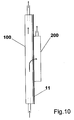
- Fig. 10 is a side view of the cell of the invention illustrating the circulation of the electrolyte.
- the metal ion bearing electrolyte is fed in the bottom part of the cathode shell (100) through the nozzle and the draft tube (not shown), and a stream thereof enters the anode shell (200) in correspondence of the foraminous or porous region of the diaphragm (11) while most of it is used to establish the spouted bed within the cathode shell (100).
- the electrolyte is then discharged in the upper part of both shells and recirculated.
- each single cell element is constructed, by bolting or otherwise fastening each anode shell with the correspondent cathode shell, prior to stacking the elements.
- the single cell elements are stacked interposing contact strips therebetween. The contact strips are preferably welded to the anodic plates.
- the cell elements may not include a semi-permeable diaphragm, an ion-exchange medium such as an ion-exchange membrane being sufficient.
- an ion-exchange medium such as an ion-exchange membrane being sufficient.
- this embodiment is however less preferred as a continuous process becomes more cumbersome to establish with separate anolyte and catholyte, each requiring ion concentration monitoring and restoring.
Landscapes
- Chemical & Material Sciences (AREA)
- Organic Chemistry (AREA)
- Chemical Kinetics & Catalysis (AREA)
- Electrochemistry (AREA)
- Materials Engineering (AREA)
- Metallurgy (AREA)
- Engineering & Computer Science (AREA)
- Electrolytic Production Of Metals (AREA)
- Fuel Cell (AREA)
- Water Treatment By Electricity Or Magnetism (AREA)
- Electrolytic Production Of Non-Metals, Compounds, Apparatuses Therefor (AREA)
- Separation Using Semi-Permeable Membranes (AREA)
- Cell Electrode Carriers And Collectors (AREA)
- Electrodes For Compound Or Non-Metal Manufacture (AREA)
Claims (54)
- Zellenelement einer laminierten Zellmatrix zur elektrolytischen Extraktion von Metall aus Metallionenlösungen, umfassend eine Anodenschale und eine Kathodenschale, welche durch eine isolierende Membran getrennt sind, wobei die Anodenschale von einer anodischen Platte, welche mit zumindest einem leitenden Vorsprung zum Übertragen von elektrischem Gleichstrom an die Anode ausgestattet ist, begrenzt ist, die Kathodenschale von einer kathodischen Platte begrenzt ist und mit zumindest einem Saugrohr ausgestattet ist, welches dazu ausgebildet ist, ein Sprudelbett metallischer Perlen herzustellen, wobei die Membran Perforationen in Entsprechung des Sprudelbetts der metallischen Perlen umfasst, wodurch eine freie Zirkulation des Elektrolyts ermöglicht, während der Durchlass der metallischen Perlen von dem kathodischen Kompartiment zu dem anodischen Kompartiment verhindert wird.
- Zellenelement nach Anspruch 1, wobei der zumindest eine leitende Vorsprung als Rippe ausgebildet ist.
- Zellenelement nach Anspruch 2, wobei die Rippen eine erste Hauptfläche, an welcher die Anode befestigt ist, und eine zweite Hauptfläche ausgestattet mit einer Kontaktleiste aufweist, wobei die Kontaktleiste mit der anodischen Platte verschweißt ist.
- Zellenelement nach Anspruch 2 oder 3, wobei die Anodenschale ferner rippenartige Abstandhalter umfasst.
- Zellenelement nach den vorhergehenden Ansprüchen, wobei die Kathodenschale aus einer Reihe von Stangen gebaut ist.
- Zellenelement nach Anspruch 5, wobei die Stangen rechteckig ausgebildet sind.
- Zellenelement nach den vorhergehenden Ansprüchen, wobei die Kathodenschale zumindest ein Kontrollfenster umfasst.
- Zellenelement nach den vorhergehenden Ansprüchen, wobei die Anodenschale und die Kathodenschale periphere ebene Regionen wie Rahmen oder Flansche zum Befestigen der Anodenschale an der Kathodenschale umfasst.
- Zellenelement nach den vorhergehenden Ansprüchen, wobei die Anodenschale aus Titan oder einer Legierung davon ist, und die Kathodenschale aus Edelstahl, Nickel oder Titan ist.
- Zellenelement nach Anspruch 9, wobei die Anode eine kleine Öffnungen aufweisende Titanstruktur auf zumindest einer Fläche mit Edelmetallen oder Edelmetalloxiden beschichtet ist.
- Zellenelement nach Anspruch 9 oder 10, wobei die Anodenschale in Kontakt mit der Kathodenschale des benachbarten Zellelements in der Zellmatrix mit zumindest einer bimetallischen Leiste dazwischen angeordnet steht.
- Zellenelement nach Anspruch 11, wobei die zumindest eine bimetallische Leiste mit zumindest der Kathodenschale oder der Anodenschale verschweißt ist.
- Zellenelement nach Anspruch 12, wobei die zumindest eine bimetallische Leiste mit der Anodenschale in Übereinstimmung mit dem zumindest einen leitenden Vorsprungs verschweißt ist.
- Zellenelement nach Anspruch 13, wobei die zumindest eine bimetallische Leiste und der zumindest eine leitende Vorsprung in einem einzigen Schritt an die Anodenschale angeschweißt werden.
- Zellenelement nach den vorhergehenden Ansprüchen, wobei die isolierende Membran eine vollflächige Dichtung bildet, welche zu der hydraulischen Dichtung zwischen der Anodenschale und der Kathodenschale zumindest in dem peripheren Teil beiträgt.
- Zellenelement nach Anspruch 15, wobei die isolierende Membran eine zusätzliche isolierende Maske entsprechend der Bereiche, welche in Kontakt mit den Außenkante der Anode und/oder den vertikalen Kanten des zumindest einen Saugrohrs stehen, umfasst.
- Zellenelement nach den vorhergehenden Ansprüchen, wobei die isolierende Membran aus einem Gewebe besteht.
- Zellenelement nach Anspruch 17, wobei das Gewebe als glattes oder als umgekehrtes Tressengewebe gewebt ist.
- Zellenelement nach Anspruch 18, wobei das Gewebe ein Verhältnis von Schussdraht- zu Kettendrahtdurchmesser zwischen 1,15 und 1,5 aufweist.
- Zellenelement nach Anspruch 19, wobei das Gewebe ein Verhältnis von Schussdraht- zu Kettendrahtdurchmesser von etwa 5:4 aufweist.
- Zellenelement nach Anspruch 17 bis 20, wobei das Verhältnis von Kettendrahtabstand zu Kettendrahtdurchmesser größer als 3 ist.
- Zellenelement nach Anspruch 17 bis 21, wobei das Gewebe eine Dicke zwischen 0,4 und 0,6 mm aufweist.
- Zellenelement nach Anspruch 17 bis 22, wobei das Gewebe ein Polyestergewebe ist.
- Zellenelement nach Anspruch 10, wobei die isolierende Membran dadurch erhalten wird, dass eine isolierende Beschichtung auf die Oberfläche der kleine Öffnungen aufweisenden Titananode gegenüberliegend der zumindest einen Fläche beschichtet mit Edelmetallen oder Edelmetalloxiden aufgetragen wird.
- Zellenelement nach Anspruch 24, wobei die isolierende Beschichtung eine keramische Beschichtung ist.
- Zellenelement nach Anspruch 25, wobei die keramische Beschichtung aus der Gruppe bestehend aus Ventilmetalloxiden und Siliziumcarbid ausgesucht wird.
- Zellenelement nach Anspruch 26, wobei die keramische Beschichtung durch Plasmaspritzen aufgetragen wird.
- Zellenelement nach Anspruch 24, wobei die isolierende Beschichtung ein fluoriertes Polymermaterial umfasst.
- Zellenelement nach den vorhergehenden Ansprüchen, wobei zumindest ein Saugrohr ein rechteckiges Rohr ist.
- Zellenelement nach Anspruch 29, wobei das rechteckige Rohr aus einem korrosionsresistenten Metall, bevorzugt Edelstahl oder Titan, gefertigt ist.
- Zellenelement nach Anspruch 30, wobei das metallische rechteckige Rohr eine isolierende Außenschicht und/oder ein Schaumstoffklebeband zumindest an den zwei Hauptflächen aufweist, welche parallel zu der anodischen und der kathodischen Platte angeordnet sind.
- Zellenelement nach Anspruch 29 bis 31, wobei die Tiefe des rechteckigen Rohres äquivalent ist zu der Entfernung zwischen der kathodischen Platte, welche die Kathodenschale begrenzt, und der Membran.
- Zellenelement nach Anspruch 29 bis 32, wobei das untere Ende des zumindest einen Saugrohrs einen vergrößerten Eingang bezüglich der Rohrbreite aufweist.
- Zellenelement nach Anspruch 29 bis 33, wobei das zumindest eine Saugrohr pfeilförmige Elemente aufweist, welche an seinem Unterteil angeordnet sind, wobei deren Winkel mit der horizontalen zwischen 60 und 80° und bevorzugt bei etwa 70° liegt.
- Zellenelement nach den vorhergehenden Ansprüchen, wobei das zumindest eine Saugrohr eine Basis umfasst, welche mit zumindest einer Düse zum Einspeisen des Elektrolyts ausgestattet ist, wodurch eine Bewegung erzeugt wird, mittels welcher das Sprudelbett metallischer Perlen herstellbar ist.
- Zellenelement nach Anspruch 35, wobei die zumindest eine Düse eine Doppeldüse ist, welche einen äußeren Teil, welcher an der Basis der Zelle angeordnet ist, und einen inneren Teil, welcher sich innerhalb oder nahe dem Eingang des zumindest einen Saugrohrs erstreckt, umfasst.
- Zellenelement nach Anspruch 35 oder 36, wobei der innere Teil der Doppeldüse Perforationen aufweist, welche den Durchtritt von Elektrolyt ermöglichen und den Durchtritt der metallischen Perlen verhindern.
- Zellenelement nach den vorhergehenden Ansprüchen, ferner umfassend zumindest einen Abweiser, welcher über dem oberen Ende des zumindest einen Saugrohrs angeordnet ist und geeignet zum Kontrollieren der Höhe des Sprudelbetts ist.
- Zellenelement nach Anspruch 38, wobei der zumindest eine Abweiser im Allgemeinen dachförmig ausgebildet ist.
- Zellenelement nach Anspruch 38 oder 39, wobei der zumindest eine Abweiser Löcher aufweist, welche den freien Durchtritt von Elektrolyt erlauben und den Durchtritt der metallischen Perlen verhindern.
- Zellenelement nach den vorhergehenden Ansprüchen, ferner umfassend ein Perlenüberlaufsystem, welches zumindest einen Überlauf, welcher in einer zum oberen Ende des zumindest einen Saugrohrs benachbarten Höhe und einem Tank zum Sammeln der übergeflossenen Perlen aufweist.
- Zellenelement nach Anspruch 41, wobei der Tank Mittel zum Ausstoßen der übergeflossenen Perlen vom Boden umfasst.
- Zellenelement nach Anspruch 41 oder 42, wobei der Tank einen kegelförmigen Boden aufweist.
- Zellenelement nach den vorhergehenden Ansprüchen, ferner umfassend ein Elektrolytabflussrohr, welches ein Filterelement umfasst, welches den Abfluss des Elektrolyts aus der Zelle ermöglicht, während der Abfluss der metallischen Perlen verhindert wird.
- Zellenelement nach den vorhergehenden Ansprüchen, ferner umfassend eine Perlenabflussvorrichtung zum Ausstoßen der metallischen Perlen daraus, welche ein Abflussrohr und ein T-förmiges Trennungselement aufweist, welches in seinem horizontalen Schenkel mit Elektrolyt gespeist wird.
- Reihe gestapelter Zellenelemente zur elektrolytischen Extraktion, wobei jedes Zellenelement eine Anodenschale begrenzt durch eine anodische Platte und eine Kathodenschale begrenzt durch eine kathodische Platte und umfassend ein Saugrohr, welches ein Sprudelbett metallischer Perlen herstellt, umfasst, wobei die anodische Platte mit der kathodischen Platte der benachbarten Zelle in der Reihe in Kontakt steht.
- Reihe nach Anspruch 46, wobei die anodische Platte mit der kathodischen Platte der benachbarten Zelle über eine bimetallische Kontaktleiste in Kontakt steht.
- Reihe nach Anspruch 46 oder 47, wobei die Anodenschale und die Kathodenschale jedes Zellenelements aneinander befestigt werden bevor die Zellenelemente gestapelt wird.
- Reihe nach den Ansprüchen 46 bis 48, wobei die Zellenelemente Zellenelemente der Ansprüche 1 bis 45 sind.
- Verfahren zur elektrolytischen Extraktion eines Metalls umfassend Einspeisen metallischer Perlen in das kathodische Kompartiment eines Zellenelements der Ansprüche 1 bis 45, in elektrischen Kontakt bringen der Perlen mit der kathodischen Platte und Einbringen der Perlen, welche einem kathodischen Potential ausgesetzt sind, in einem Sprudelbett unter der Einwirkung eines metallionhaltigen Elektrolyts, welcher über das zumindest eine Saugrohr eingespeist wird.
- Verfahren nach Anspruch 50, wobei das Sprudelbett aus zumindest einem perlengefüllten im Allgemeinen rechteckigen Ringraum gebildet ist, welcher auf einer Seite des zumindest einen Saugrohrs angeordnet ist.
- Verfahren nach Anspruch 50, wobei das Sprudelbett aus zwei perlengefüllten im Allgemeinen rechteckig geformten Ringräumen gebildet ist, welche auf entgegengesetzten Seiten des zumindest einen Saugrohres angeordnet sind.
- Verfahren nach Anspruch 51 oder 52, wobei die zwei perlengefüllten rechteckig geformten Ringräume die Selbstbildung sich bewegender Kegel von Perlen ermöglicht, welche die unteren Ecken der Kathodenschale ausfüllen und die natürliche Bildung von Perlenfließkanälen in die vertikale Lücke unterhalb der Basis des zumindest einen Saugrohres ermöglicht.
- Verfahren nach den Ansprüchen 50 bis 53, wobei die Metalle, welche elektrische extrahiert werden, aus der Gruppe bestehend aus Kupfer, Zinn, Mangan, Zink, Nickel, Chrom und Kobalt ausgewählt wird.
Applications Claiming Priority (3)
| Application Number | Priority Date | Filing Date | Title |
|---|---|---|---|
| IT2002MI001524A ITMI20021524A1 (it) | 2002-07-11 | 2002-07-11 | Cella con elettrodo a letto in eruzione per elettrodeposiwione di metalli |
| ITMI20021524 | 2002-07-11 | ||
| PCT/EP2003/007541 WO2004007805A2 (en) | 2002-07-11 | 2003-07-11 | Spouted bed electrode cell for metal electrowinning |
Publications (2)
| Publication Number | Publication Date |
|---|---|
| EP1521867A2 EP1521867A2 (de) | 2005-04-13 |
| EP1521867B1 true EP1521867B1 (de) | 2013-09-04 |
Family
ID=30012503
Family Applications (1)
| Application Number | Title | Priority Date | Filing Date |
|---|---|---|---|
| EP03735701.9A Expired - Lifetime EP1521867B1 (de) | 2002-07-11 | 2003-07-11 | Sprudelbettelektroden-zelle zur elektrogewinnung von metallen |
Country Status (13)
| Country | Link |
|---|---|
| US (1) | US7494579B2 (de) |
| EP (1) | EP1521867B1 (de) |
| CN (1) | CN100360715C (de) |
| AU (1) | AU2003238069B2 (de) |
| BR (1) | BR0312610B1 (de) |
| CA (1) | CA2491940C (de) |
| ES (1) | ES2439223T3 (de) |
| IT (1) | ITMI20021524A1 (de) |
| MX (1) | MXPA05000469A (de) |
| PE (1) | PE20040250A1 (de) |
| RU (1) | RU2324770C2 (de) |
| WO (1) | WO2004007805A2 (de) |
| ZA (1) | ZA200500724B (de) |
Cited By (1)
| Publication number | Priority date | Publication date | Assignee | Title |
|---|---|---|---|---|
| TWI840419B (zh) * | 2019-09-25 | 2024-05-01 | 日商迪諾拉永久電極股份有限公司 | 包含電極之疊層構造體 |
Families Citing this family (15)
| Publication number | Priority date | Publication date | Assignee | Title |
|---|---|---|---|---|
| US5260798A (en) | 1989-11-01 | 1993-11-09 | Aura Systems, Inc. | Pixel intensity modulator |
| ITMI20030382A1 (it) * | 2003-03-04 | 2004-09-05 | De Nora Elettrodi Spa | Metodo per la deposizione elettrolitica di rame in soluzione cloridrica. |
| ITMI20031270A1 (it) * | 2003-06-24 | 2004-12-25 | De Nora Elettrodi Spa | Cella con catodo a letto cadente per elettrodeposizioni di metalli. |
| US8202411B2 (en) * | 2008-03-19 | 2012-06-19 | Eltron Research & Development, Inc. | Electrowinning apparatus and process |
| RU2404927C2 (ru) * | 2008-11-24 | 2010-11-27 | Федеральное государственное образовательное учреждение высшего профессионального образования Санкт-Петербургский государственный университет | Способ извлечения благородных металлов из водных растворов и устройство для его реализации |
| CN102433636B (zh) * | 2010-09-29 | 2014-06-18 | 辽宁博联过滤有限公司 | 一种电解镍用机织隔膜布及其织造方法 |
| CN102877091A (zh) * | 2012-06-29 | 2013-01-16 | 江苏晨力环保科技有限公司 | 一种锰电解用隔膜框 |
| DE102012015802A1 (de) * | 2012-08-10 | 2014-02-13 | Thyssenkrupp Uhde Gmbh | Verfahren zur Herstellung von Elektrolysezellen-Kontaktstreifen |
| ITMI20130505A1 (it) * | 2013-04-04 | 2014-10-05 | Industrie De Nora Spa | Cella per estrazione elettrolitica di metalli |
| CN106011948A (zh) * | 2016-08-01 | 2016-10-12 | 舒城联科表面处理有限公司 | 一种旋流电解用始极片的改良处理方法 |
| CN108123179B (zh) * | 2016-11-29 | 2020-02-18 | 德阳九鼎智远知识产权运营有限公司 | 电动汽车动力电池 |
| ES2682960B1 (es) * | 2017-03-21 | 2019-07-05 | Univ Del Pais Vasco / Euskal Herriko Unibertsitatea | Confinador de fuente para contactor de lecho en surtidor y contactor de lecho en surtidor |
| CN107338457A (zh) * | 2017-08-25 | 2017-11-10 | 重庆科技学院 | 一种新型回收金属二次资源的电解槽 |
| CN109881230A (zh) * | 2019-02-20 | 2019-06-14 | 广东星耀光大智能装备有限公司 | 一种片式元件电镀表面清洗装置 |
| WO2024263955A1 (en) | 2023-06-21 | 2024-12-26 | SiTration, Inc. | Methods and apparatus for extracting metals from materials |
Family Cites Families (10)
| Publication number | Priority date | Publication date | Assignee | Title |
|---|---|---|---|---|
| IE39814B1 (en) * | 1973-08-03 | 1979-01-03 | Parel Sa | Electrochemical process and apparatus |
| GB1497542A (en) * | 1974-05-30 | 1978-01-12 | Parel Sa | Electrochemical apparatus |
| IT1163737B (it) * | 1979-11-29 | 1987-04-08 | Oronzio De Nora Impianti | Elettrolizzatore bipolare comprendente mezzi per generare la ricircolazione interna dell'elettrolita e procedimento di elettrolisi |
| US5013414A (en) * | 1989-04-19 | 1991-05-07 | The Dow Chemical Company | Electrode structure for an electrolytic cell and electrolytic process used therein |
| US5635051A (en) * | 1995-08-30 | 1997-06-03 | The Regents Of The University Of California | Intense yet energy-efficient process for electrowinning of zinc in mobile particle beds |
| US5958210A (en) * | 1996-11-21 | 1999-09-28 | The Regents Of The University Of California | Efficient electrowinning of zinc from alkaline electrolytes |
| EP0952910B1 (de) * | 1997-01-10 | 2003-04-02 | Beamech Group Limited | Vorrichtung und verfahren zum herstellen von polymerschaum |
| US6936142B2 (en) * | 1997-12-22 | 2005-08-30 | George Hradil | Spouted bed apparatus for contacting objects with a fluid |
| DE19959079A1 (de) * | 1999-12-01 | 2001-06-07 | Bayer Ag | Elektrochemische Zelle für Elektrolyseure mit Einzelelementtechnik |
| CN100386474C (zh) | 2000-12-28 | 2008-05-07 | 技术公司 | 用流体接触物体的喷泉床 |
-
2002
- 2002-07-11 IT IT2002MI001524A patent/ITMI20021524A1/it unknown
-
2003
- 2003-07-08 PE PE2003000685A patent/PE20040250A1/es not_active Application Discontinuation
- 2003-07-11 BR BRPI0312610-2A patent/BR0312610B1/pt not_active IP Right Cessation
- 2003-07-11 AU AU2003238069A patent/AU2003238069B2/en not_active Ceased
- 2003-07-11 MX MXPA05000469A patent/MXPA05000469A/es active IP Right Grant
- 2003-07-11 US US10/520,955 patent/US7494579B2/en not_active Expired - Fee Related
- 2003-07-11 EP EP03735701.9A patent/EP1521867B1/de not_active Expired - Lifetime
- 2003-07-11 CA CA2491940A patent/CA2491940C/en not_active Expired - Fee Related
- 2003-07-11 CN CNB038164450A patent/CN100360715C/zh not_active Expired - Fee Related
- 2003-07-11 ES ES03735701.9T patent/ES2439223T3/es not_active Expired - Lifetime
- 2003-07-11 WO PCT/EP2003/007541 patent/WO2004007805A2/en not_active Ceased
- 2003-07-11 RU RU2005103606/02A patent/RU2324770C2/ru not_active IP Right Cessation
-
2005
- 2005-01-25 ZA ZA200500724A patent/ZA200500724B/en unknown
Cited By (1)
| Publication number | Priority date | Publication date | Assignee | Title |
|---|---|---|---|---|
| TWI840419B (zh) * | 2019-09-25 | 2024-05-01 | 日商迪諾拉永久電極股份有限公司 | 包含電極之疊層構造體 |
Also Published As
| Publication number | Publication date |
|---|---|
| RU2005103606A (ru) | 2005-07-20 |
| BR0312610A (pt) | 2005-04-19 |
| ZA200500724B (en) | 2006-04-26 |
| EP1521867A2 (de) | 2005-04-13 |
| CN100360715C (zh) | 2008-01-09 |
| ITMI20021524A1 (it) | 2004-01-12 |
| WO2004007805A3 (en) | 2004-09-16 |
| ES2439223T3 (es) | 2014-01-22 |
| WO2004007805A2 (en) | 2004-01-22 |
| CN1668782A (zh) | 2005-09-14 |
| US20060124452A1 (en) | 2006-06-15 |
| AU2003238069B2 (en) | 2008-07-31 |
| CA2491940C (en) | 2011-11-01 |
| AU2003238069A1 (en) | 2004-02-02 |
| MXPA05000469A (es) | 2005-03-23 |
| US7494579B2 (en) | 2009-02-24 |
| CA2491940A1 (en) | 2004-01-22 |
| PE20040250A1 (es) | 2004-06-14 |
| BR0312610B1 (pt) | 2012-12-11 |
| RU2324770C2 (ru) | 2008-05-20 |
Similar Documents
| Publication | Publication Date | Title |
|---|---|---|
| CA2491940C (en) | Spouted bed electrode cell for metal electrowinning | |
| US4308122A (en) | Apparatus for waste treatment equipment | |
| US3981787A (en) | Electrochemical circulating bed cell | |
| FI67728B (fi) | Bipolaer film- eller membranelektrolyseringsanordning | |
| RU2190701C2 (ru) | Биполярный электролизер с ионообменной мембраной | |
| US4019968A (en) | Electrochemical cell | |
| EP0064417A1 (de) | Elektrochemische Zelle und Methoden zur Durchführung von elektrochemischen Reaktionen | |
| US4911804A (en) | Electrochemical reactor for copper removal from barren solutions | |
| CN107750284B (zh) | 电极组件、电极结构以及电解器 | |
| US3755105A (en) | Vacuum electrical contacts for use in electrolytic cells | |
| US3976550A (en) | Horizontal, planar, bipolar diaphragm cells | |
| US4073715A (en) | Electrolysis cell with vertical anodes and cathodes and method of operation | |
| US20130153435A1 (en) | High surface area cathode assembly, system including the assembly, and method of using same | |
| EP0610946A1 (de) | Aktivierte Kathode für Chlor-alkali Zellen und Verfahren zu deren Herstellung | |
| US4035278A (en) | Electrolytic cells | |
| US4568433A (en) | Electrolytic process of an aqueous alkali metal halide solution | |
| US2749301A (en) | Mercury type, caustic, chlorine cell | |
| US4048046A (en) | Electrolytic cell design | |
| WO2007071714A1 (en) | Electrolytic cell for metal deposition | |
| EP0110425A2 (de) | Elektrolytisches Verfahren für eine wässrige Alkalimetall-Halogenidlösung und Elektrolysezelle dafür | |
| Robinson et al. | Via Bistolfi, 35, Milan, Italy 20134 | |
| US3445374A (en) | Alkali chloride electrolytic mercury cells | |
| CA2175270A1 (en) | Anode structure for electrowinning metals by anodic processes different from oxygen evolution and for electrochemical processes with separator | |
| CA1050478A (en) | Electrolytic cells | |
| JPH04289185A (ja) | 複極式電解槽 |
Legal Events
| Date | Code | Title | Description |
|---|---|---|---|
| PUAI | Public reference made under article 153(3) epc to a published international application that has entered the european phase |
Free format text: ORIGINAL CODE: 0009012 |
|
| 17P | Request for examination filed |
Effective date: 20050112 |
|
| AK | Designated contracting states |
Kind code of ref document: A2 Designated state(s): AT BE BG CH CY CZ DE DK EE ES FI FR GB GR HU IE IT LI LU MC NL PT RO SE SI SK TR |
|
| AX | Request for extension of the european patent |
Extension state: AL LT LV MK |
|
| DAX | Request for extension of the european patent (deleted) | ||
| RAP1 | Party data changed (applicant data changed or rights of an application transferred) |
Owner name: INDUSTRIE DE NORA S.P.A. |
|
| GRAP | Despatch of communication of intention to grant a patent |
Free format text: ORIGINAL CODE: EPIDOSNIGR1 |
|
| GRAS | Grant fee paid |
Free format text: ORIGINAL CODE: EPIDOSNIGR3 |
|
| GRAA | (expected) grant |
Free format text: ORIGINAL CODE: 0009210 |
|
| AK | Designated contracting states |
Kind code of ref document: B1 Designated state(s): AT BE BG CH CY CZ DE DK EE ES FI FR GB GR HU IE IT LI LU MC NL PT RO SE SI SK TR |
|
| REG | Reference to a national code |
Ref country code: GB Ref legal event code: FG4D |
|
| REG | Reference to a national code |
Ref country code: CH Ref legal event code: EP |
|
| REG | Reference to a national code |
Ref country code: AT Ref legal event code: REF Ref document number: 630604 Country of ref document: AT Kind code of ref document: T Effective date: 20130915 |
|
| REG | Reference to a national code |
Ref country code: IE Ref legal event code: FG4D |
|
| REG | Reference to a national code |
Ref country code: DE Ref legal event code: R096 Ref document number: 60344860 Country of ref document: DE Effective date: 20131031 |
|
| REG | Reference to a national code |
Ref country code: AT Ref legal event code: MK05 Ref document number: 630604 Country of ref document: AT Kind code of ref document: T Effective date: 20130904 |
|
| REG | Reference to a national code |
Ref country code: ES Ref legal event code: FG2A Ref document number: 2439223 Country of ref document: ES Kind code of ref document: T3 Effective date: 20140122 |
|
| REG | Reference to a national code |
Ref country code: NL Ref legal event code: VDEP Effective date: 20130904 |
|
| PG25 | Lapsed in a contracting state [announced via postgrant information from national office to epo] |
Ref country code: AT Free format text: LAPSE BECAUSE OF FAILURE TO SUBMIT A TRANSLATION OF THE DESCRIPTION OR TO PAY THE FEE WITHIN THE PRESCRIBED TIME-LIMIT Effective date: 20130904 Ref country code: SE Free format text: LAPSE BECAUSE OF FAILURE TO SUBMIT A TRANSLATION OF THE DESCRIPTION OR TO PAY THE FEE WITHIN THE PRESCRIBED TIME-LIMIT Effective date: 20130904 Ref country code: CY Free format text: LAPSE BECAUSE OF FAILURE TO SUBMIT A TRANSLATION OF THE DESCRIPTION OR TO PAY THE FEE WITHIN THE PRESCRIBED TIME-LIMIT Effective date: 20130703 |
|
| REG | Reference to a national code |
Ref country code: NL Ref legal event code: VDEP Effective date: 20130904 |
|
| PG25 | Lapsed in a contracting state [announced via postgrant information from national office to epo] |
Ref country code: GR Free format text: LAPSE BECAUSE OF FAILURE TO SUBMIT A TRANSLATION OF THE DESCRIPTION OR TO PAY THE FEE WITHIN THE PRESCRIBED TIME-LIMIT Effective date: 20131205 Ref country code: SI Free format text: LAPSE BECAUSE OF FAILURE TO SUBMIT A TRANSLATION OF THE DESCRIPTION OR TO PAY THE FEE WITHIN THE PRESCRIBED TIME-LIMIT Effective date: 20130904 |
|
| PG25 | Lapsed in a contracting state [announced via postgrant information from national office to epo] |
Ref country code: CY Free format text: LAPSE BECAUSE OF FAILURE TO SUBMIT A TRANSLATION OF THE DESCRIPTION OR TO PAY THE FEE WITHIN THE PRESCRIBED TIME-LIMIT Effective date: 20130904 |
|
| PG25 | Lapsed in a contracting state [announced via postgrant information from national office to epo] |
Ref country code: SK Free format text: LAPSE BECAUSE OF FAILURE TO SUBMIT A TRANSLATION OF THE DESCRIPTION OR TO PAY THE FEE WITHIN THE PRESCRIBED TIME-LIMIT Effective date: 20130904 Ref country code: NL Free format text: LAPSE BECAUSE OF FAILURE TO SUBMIT A TRANSLATION OF THE DESCRIPTION OR TO PAY THE FEE WITHIN THE PRESCRIBED TIME-LIMIT Effective date: 20130904 Ref country code: CZ Free format text: LAPSE BECAUSE OF FAILURE TO SUBMIT A TRANSLATION OF THE DESCRIPTION OR TO PAY THE FEE WITHIN THE PRESCRIBED TIME-LIMIT Effective date: 20130904 Ref country code: RO Free format text: LAPSE BECAUSE OF FAILURE TO SUBMIT A TRANSLATION OF THE DESCRIPTION OR TO PAY THE FEE WITHIN THE PRESCRIBED TIME-LIMIT Effective date: 20130904 Ref country code: EE Free format text: LAPSE BECAUSE OF FAILURE TO SUBMIT A TRANSLATION OF THE DESCRIPTION OR TO PAY THE FEE WITHIN THE PRESCRIBED TIME-LIMIT Effective date: 20130904 |
|
| REG | Reference to a national code |
Ref country code: DE Ref legal event code: R097 Ref document number: 60344860 Country of ref document: DE |
|
| PG25 | Lapsed in a contracting state [announced via postgrant information from national office to epo] |
Ref country code: PT Free format text: LAPSE BECAUSE OF FAILURE TO SUBMIT A TRANSLATION OF THE DESCRIPTION OR TO PAY THE FEE WITHIN THE PRESCRIBED TIME-LIMIT Effective date: 20140106 |
|
| PLBE | No opposition filed within time limit |
Free format text: ORIGINAL CODE: 0009261 |
|
| STAA | Information on the status of an ep patent application or granted ep patent |
Free format text: STATUS: NO OPPOSITION FILED WITHIN TIME LIMIT |
|
| 26N | No opposition filed |
Effective date: 20140605 |
|
| PG25 | Lapsed in a contracting state [announced via postgrant information from national office to epo] |
Ref country code: IT Free format text: LAPSE BECAUSE OF FAILURE TO SUBMIT A TRANSLATION OF THE DESCRIPTION OR TO PAY THE FEE WITHIN THE PRESCRIBED TIME-LIMIT Effective date: 20130904 |
|
| REG | Reference to a national code |
Ref country code: DE Ref legal event code: R097 Ref document number: 60344860 Country of ref document: DE Effective date: 20140605 |
|
| PG25 | Lapsed in a contracting state [announced via postgrant information from national office to epo] |
Ref country code: DK Free format text: LAPSE BECAUSE OF FAILURE TO SUBMIT A TRANSLATION OF THE DESCRIPTION OR TO PAY THE FEE WITHIN THE PRESCRIBED TIME-LIMIT Effective date: 20130904 |
|
| PGFP | Annual fee paid to national office [announced via postgrant information from national office to epo] |
Ref country code: DE Payment date: 20140721 Year of fee payment: 12 Ref country code: FI Payment date: 20140711 Year of fee payment: 12 |
|
| PGFP | Annual fee paid to national office [announced via postgrant information from national office to epo] |
Ref country code: GB Payment date: 20140721 Year of fee payment: 12 Ref country code: FR Payment date: 20140721 Year of fee payment: 12 Ref country code: ES Payment date: 20140728 Year of fee payment: 12 |
|
| PGFP | Annual fee paid to national office [announced via postgrant information from national office to epo] |
Ref country code: BE Payment date: 20140722 Year of fee payment: 12 |
|
| PG25 | Lapsed in a contracting state [announced via postgrant information from national office to epo] |
Ref country code: LU Free format text: LAPSE BECAUSE OF FAILURE TO SUBMIT A TRANSLATION OF THE DESCRIPTION OR TO PAY THE FEE WITHIN THE PRESCRIBED TIME-LIMIT Effective date: 20140711 |
|
| REG | Reference to a national code |
Ref country code: CH Ref legal event code: PL |
|
| REG | Reference to a national code |
Ref country code: IE Ref legal event code: MM4A |
|
| PG25 | Lapsed in a contracting state [announced via postgrant information from national office to epo] |
Ref country code: CH Free format text: LAPSE BECAUSE OF NON-PAYMENT OF DUE FEES Effective date: 20140731 Ref country code: LI Free format text: LAPSE BECAUSE OF NON-PAYMENT OF DUE FEES Effective date: 20140731 |
|
| PG25 | Lapsed in a contracting state [announced via postgrant information from national office to epo] |
Ref country code: IE Free format text: LAPSE BECAUSE OF NON-PAYMENT OF DUE FEES Effective date: 20140711 |
|
| REG | Reference to a national code |
Ref country code: DE Ref legal event code: R119 Ref document number: 60344860 Country of ref document: DE |
|
| GBPC | Gb: european patent ceased through non-payment of renewal fee |
Effective date: 20150711 |
|
| PG25 | Lapsed in a contracting state [announced via postgrant information from national office to epo] |
Ref country code: MC Free format text: LAPSE BECAUSE OF FAILURE TO SUBMIT A TRANSLATION OF THE DESCRIPTION OR TO PAY THE FEE WITHIN THE PRESCRIBED TIME-LIMIT Effective date: 20130904 Ref country code: GB Free format text: LAPSE BECAUSE OF NON-PAYMENT OF DUE FEES Effective date: 20150711 Ref country code: DE Free format text: LAPSE BECAUSE OF NON-PAYMENT OF DUE FEES Effective date: 20160202 |
|
| REG | Reference to a national code |
Ref country code: FR Ref legal event code: ST Effective date: 20160331 |
|
| PG25 | Lapsed in a contracting state [announced via postgrant information from national office to epo] |
Ref country code: FR Free format text: LAPSE BECAUSE OF NON-PAYMENT OF DUE FEES Effective date: 20150731 Ref country code: BG Free format text: LAPSE BECAUSE OF FAILURE TO SUBMIT A TRANSLATION OF THE DESCRIPTION OR TO PAY THE FEE WITHIN THE PRESCRIBED TIME-LIMIT Effective date: 20130904 Ref country code: FI Free format text: LAPSE BECAUSE OF NON-PAYMENT OF DUE FEES Effective date: 20150711 |
|
| PG25 | Lapsed in a contracting state [announced via postgrant information from national office to epo] |
Ref country code: HU Free format text: LAPSE BECAUSE OF FAILURE TO SUBMIT A TRANSLATION OF THE DESCRIPTION OR TO PAY THE FEE WITHIN THE PRESCRIBED TIME-LIMIT; INVALID AB INITIO Effective date: 20030711 |
|
| REG | Reference to a national code |
Ref country code: ES Ref legal event code: FD2A Effective date: 20160826 |
|
| PG25 | Lapsed in a contracting state [announced via postgrant information from national office to epo] |
Ref country code: ES Free format text: LAPSE BECAUSE OF NON-PAYMENT OF DUE FEES Effective date: 20150712 |
|
| PG25 | Lapsed in a contracting state [announced via postgrant information from national office to epo] |
Ref country code: BE Free format text: LAPSE BECAUSE OF NON-PAYMENT OF DUE FEES Effective date: 20150731 |
|
| PG25 | Lapsed in a contracting state [announced via postgrant information from national office to epo] |
Ref country code: TR Free format text: LAPSE BECAUSE OF NON-PAYMENT OF DUE FEES Effective date: 20150711 |