EP1521224A1 - Vehicle emergency notification system and related method - Google Patents
Vehicle emergency notification system and related method Download PDFInfo
- Publication number
- EP1521224A1 EP1521224A1 EP04255433A EP04255433A EP1521224A1 EP 1521224 A1 EP1521224 A1 EP 1521224A1 EP 04255433 A EP04255433 A EP 04255433A EP 04255433 A EP04255433 A EP 04255433A EP 1521224 A1 EP1521224 A1 EP 1521224A1
- Authority
- EP
- European Patent Office
- Prior art keywords
- collision
- vehicle
- emergency notification
- emergency
- base station
- Prior art date
- Legal status (The legal status is an assumption and is not a legal conclusion. Google has not performed a legal analysis and makes no representation as to the accuracy of the status listed.)
- Granted
Links
Images


Classifications
-
- G—PHYSICS
- G08—SIGNALLING
- G08B—SIGNALLING OR CALLING SYSTEMS; ORDER TELEGRAPHS; ALARM SYSTEMS
- G08B25/00—Alarm systems in which the location of the alarm condition is signalled to a central station, e.g. fire or police telegraphic systems
- G08B25/01—Alarm systems in which the location of the alarm condition is signalled to a central station, e.g. fire or police telegraphic systems characterised by the transmission medium
- G08B25/016—Personal emergency signalling and security systems
-
- G—PHYSICS
- G08—SIGNALLING
- G08B—SIGNALLING OR CALLING SYSTEMS; ORDER TELEGRAPHS; ALARM SYSTEMS
- G08B25/00—Alarm systems in which the location of the alarm condition is signalled to a central station, e.g. fire or police telegraphic systems
- G08B25/001—Alarm cancelling procedures or alarm forwarding decisions, e.g. based on absence of alarm confirmation
Landscapes
- Business, Economics & Management (AREA)
- Emergency Management (AREA)
- Physics & Mathematics (AREA)
- General Physics & Mathematics (AREA)
- Engineering & Computer Science (AREA)
- Computer Security & Cryptography (AREA)
- Alarm Systems (AREA)
- Air Bags (AREA)
Abstract
Description
- The present invention relates to a vehicle emergency notification system and a method and, more particularly, to an emergency notification system and its related method wherein in the even of a collision of a vehicle typically with a pedestrian, an emergency notification signal is transmitted to a rescue center.
- Japanese Patent Application Laid-Open Publication Nos. 2000-115413 and 2002-187510 disclose technology for detecting a collision of a vehicle to recognize the activation of an air bag for thereby actuating an emergency notification system to call a rescue request in the event of an accident.
- Further, a lift-up hood system has been proposed wherein a collision detection sensor, mounted on a bumper of the vehicle, senses the collision between a vehicle and a pedestrian and, when the collision is detected, a hood (bonnet) of the vehicle is lifted upward to minimize effect to the pedestrian.
- However, upon studies conducted by the present inventor, with such a lift-up hood system, since the collision is detected by a touch sensor, it is hard to distinguish and discriminate if the pedestrian is involved in the collision or an object other than the pedestrian is involved in the collision, and it is conceivable that there is still room for improvement over appropriateness in judgment as to whether to activate the emergency notification system in the event of the collision.
- That is, even if such a lift-up hood system is merely combined with the emergency notification system adapted to operate in conjunction with the activation of the air bag system, the emergency notification signal is liable to be transmitted even in the absence of a need to provide notification like in the event of a mild contact between the vehicle and the object.
- The present invention has been completed upon consideration of the above studies conducted by the present inventor and has an object to provide an emergency notification system and its related method wherein when there is a need for transmitting an emergency notification signal in the event of a collision, the emergency notification signal can be reliably transmitted to a base station.
- According to one aspect of the present invention, there is provided a vehicle emergency notification system installed on a vehicle to transmit an emergency notification signal to a base station when a collision occurs, the system comprising: a collision sensor sensing a collision of a vehicle; a notification switch whose operation is permitted when the collision sensor senses the collision; and a communicating section transmitting an emergency notification signal to a base station, the communicating section allowing the emergency notification signal to be transmitted to the base station when the notification switch is turned on.
- Stated another way, according to another aspect of the present invention, there is provided a vehicle emergency notification system installed on a vehicle to transmit an emergency notification signal to a base station when a collision occurs, the system comprising: collision detection means for detecting a collision of a vehicle; notification selection means for selecting notification to a base station, operation of the notification selection means being permitted when the collision detection means detects the collision; and communication means for transmitting an emergency notification signal to the base station and operative to transmit the emergency notification signal to the base station when the notification selection means is turned on.
- In the meanwhile, according to another aspect of the present invention, there is provide a vehicle emergency notification method transmitting an emergency notification signal to a base station when a collision of a vehicle occurs, the method comprising: detecting a collision of a vehicle; displaying a notification switch when the collision is detected; and transmitting an emergency notification signal to a base station when the notification switch is turned on.
- Other and further features, advantages, and benefits of the present invention will become more apparent from the following description taken in conjunction with the following drawings.
-
- FIG. 1 is a schematic side view of a vehicle installed with a vehicle emergency notification system of an embodiment according to the present invention;
- FIG. 2 is a block diagram illustrating a structure of the vehicle emergency notification system of the presently filed embodiment;
- FIG. 3 is a view illustrating an emergency switch and a cancel switch to be displayed over a display screen of a display device of the vehicle emergency notification system of the presently filed embodiment; and
- FIG. 4 is a flowchart illustrating a basic sequence of operations of the vehicle emergency notification system of the presently filed embodiment.
-
- Hereinafter, a vehicle emergency notification system and its related method of an embodiment according to the present invention are described in detail with reference to FIGS. 1 to 4 of the accompanying drawings.
- FIG. 1 is a schematic side view of the vehicle that is installed with a vehicle emergency notification system of the presently filed embodiment. Incidentally, in FIG. 1, an arrow FR indicates a forward direction of a vehicle V and an arrow UPR indicates an upward direction of the vehicle V.
- As shown in FIG. 1, the vehicle
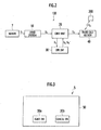
emergency notification system 100 of the presently filed embodiment is installed on the vehicle V. The vehicle V has ahood 1, serving as a closure body, which is located in an upper area of an engine room in a front part of the vehicle. Further, the vehicle V is equipped with anair bag device 3, which serves as an auxiliary restraint device for restraining an occupant in an auxiliary fashion by deploying toward the occupant, and adisplay device 5 enabled to provide the occupant with a variety of information. Incidentally, while theair bag device 3 has been shown in the drawing to assume a position in front of a driver in opposition thereto, the air bag device is not limited to such a particular layout and alteration may include a structure wherein the air bag is located in opposition to the driver at a side thereof or the air bag is located in position to other occupant. Moreover, although thedisplay device 5 typically includes a display device of a navigation device that is located at a center of an instrument panel of the vehicle, of course, the display device is not limited to such a particular structure and the display device may be suffice to have a structure that is able to provide the occupant with ease of access to obtain necessary information. - FIG. 2 is a block diagram illustrating a further detailed structure of the vehicle
emergency notification system 100. - As shown in FIG. 2, the vehicle
emergency notification system 100 is comprised of acollision sensor 7 such as an accelerator sensor, a lift-up hood system 10, an airbag control unit 20, anoperation switch 30, and an emergency call section (communication system) 40. - In particular, the lift-
up hood system 10 is enabled to alleviate impact occurring when the vehicle collides with a pedestrian, which is located typically in front of the vehicle V and caused to be moved on thehood 1 of the vehicle V rearward due to the collision, by lifting up a rear end portion 1R of thehood 1 in response to a detection signal S1 delivered from thecollision sensor 7 when thecollision sensor 7 senses the collision. Also, upon receipt of an actuation signal S2, indicative of the occurrence of the activation of the lift-up hood system 10 to lift up thehood 1, which is delivered from the lift-up hood system 10, the airbag control unit 20 activates theair bag device 3 to deploy the air bag while transmitting a permission signal S3 to theoperation switch 30, and when operation signals S4, S4' are inputted from theoperation switch 30, an emergency notification signal S5 is emergenfly outputted to theemergency call section 40. Moreover, when applied with the emergency notification signal S5 from the airbag control unit 20, theemergency call section 40 transmits an emergency notification signal S6, which carries the same content as that of the emergency notification signal S5, to arescue center 200. - FIG. 3 is a view showing an
emergency switch 30a and anearby cancel switch 30b, both forming theoperation switch 30, which are displayed over adisplay screen 50 of thedisplay device 5 used for the vehicleemergency notification system 100. - As shown in FIG. 3, the
operation switch 30 typically takes the form of a touch type switch that is displayed over thedisplay screen 50 of thedisplay device 5 of the navigation system installed on the vehicle V and includes the emergency switch (notification switch) 30a and the nearby cancel switch (switch for canceling emergency notification) 30b which is located so as to be close to theemergency switch 30a. Theswitches display screen 50, in which there is displayed a screen for navigation (normal display screen), and theswitches collision sensor 7. Incidentally, theswitches switches - Next, the operation of the vehicle
emergency notification system 100 with the structure set forth above is described with reference to FIG. 4. - FIG. 4 is a flowchart illustrating a basic sequence of operations of the vehicle
emergency notification system 100. - As shown in FIG. 4, first in step S1, if an ignition switch of the vehicle V is turned on, a series of operations are initiated and the operation proceeds to S2.
- In succeeding step S2, the lift-
up hood system 10 discriminates whether to effectuate the lift-up of thehood 1. In particular, discrimination is made to find whether thecollision sensor 7 senses the occurrence of collision between the vehicle and an obstacle, that is, whether a detection signal S1 is applied to the lift-up hood system 10. Incidentally, in this step, when discriminated that the collision with an obstacle has occurred, the operation is also executed to lift up thehood 1. In step S2, if the collision with an obstacle is detected, the operation proceeds to step S3, and if such a collision is not detected, the operation in step S2 is executed again. - In subsequent step S3, the air
bag control unit 20 executes the operation to allow the activation of theoperation switch 30 in response to an actuation signal S2 delivered from the lift-up hood system 10. In particular, a permission signal S3 is transmitted to theoperation switch 30 from the airbag control unit 20 to provide a display of theemergency switch 30a and cancelswitch 30b, shown in FIG. 3, over thedisplay screen 50 of thedisplay device 5. - Subsequently, the operation is routed to step S4 where the air
bag control unit 20 discriminates in response to an operation signal S4 to find whether an occupant touches thecancel switch 30b for turning on the same. - More particularly, when discrimination is made that, under such a condition, the occupant has touched the
cancel switch 30b to turn on the same, no need arises for transmitting an emergency notification signal and the succeeding operations are not executed to terminate the current operation. In contrast, if in step S4, discrimination is made that the occupant does not turn on thecancel switch 30b, the operation is routed to step S5. - In consecutive step S5, the air
bag control unit 20 discriminates in response to an operation signal S4' to find whether the occupant touches theemergency switch 30a to turn on the same. In particular, when the occupant turns on theemergency switch 30a in the event of a collision with a pedestrian, forming the obstacle, that is, in a case where an emergency request is needed, the operation proceeds to succeeding step S6 and in step S6, the airbag control unit 20 transmits an emergency notification signal S5 to theemergency call section 40. This allows theemergency call section 40 to transmit an emergency notification signal S6, indicating the content of the occurrence of the collision with the pedestrian, to therescue center 200 such that therescue center 200 is able to surely recognize the occurrence of such a collision. And, the series of current operations are terminated. - On the contrary, in step S5, if the air
bag control unit 20 discriminates that the occupant does not turn on theemergency switch 30a, the operation is routed back to step S4 where discrimination is executed again to find whether the occupant touches thecancel switch 30b to turn on the same. - As set forth above, with the vehicle
emergency notification system 100 of the presently filed embodiment, if thecollision sensor 7 senses the collision with the obstacle, thehood 1 is lifted up while providing a display of the operation switch (emergency switch 30a and cancelswitch 30b) 30 such that when the occupant touches theemergency switch 30a, the emergency notification signal is automatically transmitted to the rescue center, resulting in a capability of reliably calling a rescue request when needed. - Further, the emergency notification signals S5, S6 are transmitted under "AND" condition between the input of the detection signal S1, delivered from the
collision sensor 7, and the input of the operation signal S4' associated with the turning-on of theemergency switch 30a effectuated by the occupant, thereby reliably avoiding a probability in the occurrence of an emergency notification signal being transmitted as a result of inadvertent erroneous operation. - Furthermore, since the operation switch (
emergency switch 30a and cancelswitch 30b) 30 is displayed over thedisplay screen 50 of thedisplay device 5 of the navigation device during judgment of the collision, awareness ability of the occupant can be improved. - Incidentally, although the presently filed embodiment discussed above has been described in conjunction with an exemplary structure in which the air
bag control unit 20 and theemergency call section 4 are combined in use, an alternative structure may be such that the lift-up hood system 10 and theemergency call section 4 are combined and, in such case, it is possible for the lift-up hood system 10 to have a structure in which theoperation switch 30 is controlled so as to transmit the emergency notification signal S5 to theemergency call section 40. - Moreover, the presently filed embodiment may take the form of a system wherein air bag deployment operation to be performed by the air
bag control unit 20 is distinguished from hood lift-up operation to be performed by the lift-up hood system 10 whereby when the actuation signal S2 is generated by the lift-up hood system 10, a call can be established between the rescue center and the occupant. - Besides, while the presently filed embodiment has been described in conjunction with an exemplary case with a structure wherein the
touch switches operation switch 30, the operation switch is not limited thereto and it is, of course, possible to employ press button switches normally in use. - Additionally, while the presently filed embodiment has been described in conjunction with an exemplary case with a structure wherein the
operation switch 30 is comprised of theemergency switch 30a and cancelswitch 30b, thecancel switch 30b may be dispensed with when desired to simplify the structure. - Although the invention has been described above by reference to a certain embodiment of the invention, the invention is not limited to the embodiment described above. Modifications and variations of the embodiment described above will occur to those skilled in the art, in light of the teachings. The scope of the invention is defined with reference to the following claims.
Claims (9)
- A vehicle emergency notification system (100) installed on a vehicle (V) to transmit an emergency notification signal to a base station when a collision occurs, the system comprising:collision detection means (7) for detecting a collision of the vehicle;notification selection means (30a) for selecting notification to the base station, operation of the notification selection means being permitted when the collision detection means (7) detects a collision; andcommunication means (40) for transmitting an emergency notification signal to the base station, the communication means being operative to transmit the emergency notification signal to the base station when the notification selection means (30a) is turned on.
- A system as claimed in claim 1, including hood lift-up means (10) operative to lift up a hood (1) of the vehicle (V) when the collision detection means (7) detects a collision, wherein the operation of the notification selection means (30a) is permitted when the hood lift-up means is actuated.
- A system as claimed in claim 2, wherein the hood lift-up means (10) lifts up a rear end (1R) of the hood (1) upward.
- A system as claimed in any preceding claim, including an air bag control unit (20) for deploying an air bag (3) when the collision detection means (7) detects a collision, wherein the operation of the notification selection means (30a) is permitted by the air bag control unit, and the emergency notification signal is generated by the air bag control unit to be transmitted through the communication means (40) to the base station.
- A system as claimed in any preceding claim, wherein the notification selection means (30a) comprises a touch type switch to be displayed over a display screen (50) of a display device (5), installed on the vehicle (V), when the collision detection means (7) detects a collision.
- A system as claimed in any preceding claim, wherein when the notification selection means (30a) is not turned on, the emergency notification signal is not transmitted.
- A system as claimed in any preceding claim, including cancel selection means (30b) for selecting not to transmit the emergency notification signal, the cancel selection means being displayed in an area near the notification selection means (30a).
- A system as claimed in claim 7, wherein when the cancel selection means (30b) is turned on, the emergency notification signal is not transmitted.
- A vehicle emergency notification method transmitting an emergency notification signal to a base station when a collision of a vehicle occurs, the method comprising:detecting a collision of a vehicle;displaying a notification switch when the collision is detected; andtransmitting an emergency notification signal to a base station when the notification switch is turned on.
Applications Claiming Priority (2)
| Application Number | Priority Date | Filing Date | Title |
|---|---|---|---|
| JP2003346020A JP2005112043A (en) | 2003-10-03 | 2003-10-03 | Vehicular emergency reporting system |
| JP2003346020 | 2003-10-03 |
Publications (2)
| Publication Number | Publication Date |
|---|---|
| EP1521224A1 true EP1521224A1 (en) | 2005-04-06 |
| EP1521224B1 EP1521224B1 (en) | 2006-08-02 |
Family
ID=34309166
Family Applications (1)
| Application Number | Title | Priority Date | Filing Date |
|---|---|---|---|
| EP04255433A Expired - Fee Related EP1521224B1 (en) | 2003-10-03 | 2004-09-08 | Vehicle emergency notification system and related method |
Country Status (5)
| Country | Link |
|---|---|
| US (1) | US7323972B2 (en) |
| EP (1) | EP1521224B1 (en) |
| JP (1) | JP2005112043A (en) |
| CN (1) | CN1296229C (en) |
| DE (1) | DE602004001730T2 (en) |
Families Citing this family (40)
| Publication number | Priority date | Publication date | Assignee | Title |
|---|---|---|---|---|
| US7508298B2 (en) * | 2005-04-11 | 2009-03-24 | Toyota Motor Sales U.S.A., Inc. | Automatic crash notification using prerecorded messages |
| CN101228049B (en) * | 2005-04-11 | 2010-05-19 | 美国丰田汽车销售公司 | Automatic crash notification using prerecorded messages |
| US8630768B2 (en) | 2006-05-22 | 2014-01-14 | Inthinc Technology Solutions, Inc. | System and method for monitoring vehicle parameters and driver behavior |
| US9067565B2 (en) | 2006-05-22 | 2015-06-30 | Inthinc Technology Solutions, Inc. | System and method for evaluating driver behavior |
| US20080294690A1 (en) * | 2007-05-22 | 2008-11-27 | Mcclellan Scott | System and Method for Automatically Registering a Vehicle Monitoring Device |
| US7899610B2 (en) | 2006-10-02 | 2011-03-01 | Inthinc Technology Solutions, Inc. | System and method for reconfiguring an electronic control unit of a motor vehicle to optimize fuel economy |
| US8825277B2 (en) | 2007-06-05 | 2014-09-02 | Inthinc Technology Solutions, Inc. | System and method for the collection, correlation and use of vehicle collision data |
| US8666590B2 (en) | 2007-06-22 | 2014-03-04 | Inthinc Technology Solutions, Inc. | System and method for naming, filtering, and recall of remotely monitored event data |
| US9129460B2 (en) * | 2007-06-25 | 2015-09-08 | Inthinc Technology Solutions, Inc. | System and method for monitoring and improving driver behavior |
| US7999670B2 (en) * | 2007-07-02 | 2011-08-16 | Inthinc Technology Solutions, Inc. | System and method for defining areas of interest and modifying asset monitoring in relation thereto |
| US9117246B2 (en) | 2007-07-17 | 2015-08-25 | Inthinc Technology Solutions, Inc. | System and method for providing a user interface for vehicle mentoring system users and insurers |
| US8818618B2 (en) | 2007-07-17 | 2014-08-26 | Inthinc Technology Solutions, Inc. | System and method for providing a user interface for vehicle monitoring system users and insurers |
| US8577703B2 (en) * | 2007-07-17 | 2013-11-05 | Inthinc Technology Solutions, Inc. | System and method for categorizing driving behavior using driver mentoring and/or monitoring equipment to determine an underwriting risk |
| US20090051510A1 (en) * | 2007-08-21 | 2009-02-26 | Todd Follmer | System and Method for Detecting and Reporting Vehicle Damage |
| US7876205B2 (en) * | 2007-10-02 | 2011-01-25 | Inthinc Technology Solutions, Inc. | System and method for detecting use of a wireless device in a moving vehicle |
| US20090146813A1 (en) * | 2007-12-10 | 2009-06-11 | Acropolis Engineering | Automobile forgotten passenger alarm and notification |
| US20090177336A1 (en) * | 2008-01-07 | 2009-07-09 | Mcclellan Scott | System and Method for Triggering Vehicle Functions |
| DE602008005700D1 (en) * | 2008-01-15 | 2011-05-05 | Smr Patents Sarl | Emergency system for a vehicle |
| KR100999148B1 (en) * | 2008-06-02 | 2010-12-08 | 기아자동차주식회사 | Sensing System For Crush Of A Vehicle |
| US8688180B2 (en) * | 2008-08-06 | 2014-04-01 | Inthinc Technology Solutions, Inc. | System and method for detecting use of a wireless device while driving |
| JP5126012B2 (en) * | 2008-11-17 | 2013-01-23 | トヨタ自動車株式会社 | Vehicle communication control device |
| US8188887B2 (en) * | 2009-02-13 | 2012-05-29 | Inthinc Technology Solutions, Inc. | System and method for alerting drivers to road conditions |
| US20100211301A1 (en) * | 2009-02-13 | 2010-08-19 | Mcclellan Scott | System and method for analyzing traffic flow |
| US8963702B2 (en) * | 2009-02-13 | 2015-02-24 | Inthinc Technology Solutions, Inc. | System and method for viewing and correcting data in a street mapping database |
| US8892341B2 (en) * | 2009-02-13 | 2014-11-18 | Inthinc Technology Solutions, Inc. | Driver mentoring to improve vehicle operation |
| JP5491055B2 (en) * | 2009-04-02 | 2014-05-14 | 本田技研工業株式会社 | Emergency call system |
| GB201013130D0 (en) * | 2009-09-24 | 2010-09-22 | Barloworld Handling Ltd | Energy management system |
| JP5386415B2 (en) * | 2010-03-18 | 2014-01-15 | セコム株式会社 | Vehicle accident reporting device |
| JP5725002B2 (en) | 2012-12-20 | 2015-05-27 | 株式会社デンソー | 軋 轢 Accident detection system |
| US9172477B2 (en) | 2013-10-30 | 2015-10-27 | Inthinc Technology Solutions, Inc. | Wireless device detection using multiple antennas separated by an RF shield |
| JP6156168B2 (en) * | 2014-01-31 | 2017-07-05 | 株式会社デンソー | Serious accident detection device |
| CN106414181B (en) * | 2014-06-17 | 2019-08-30 | 马自达汽车株式会社 | Vehicle emergency communicator |
| US10083551B1 (en) | 2015-04-13 | 2018-09-25 | Allstate Insurance Company | Automatic crash detection |
| US9767625B1 (en) | 2015-04-13 | 2017-09-19 | Allstate Insurance Company | Automatic crash detection |
| US20170339541A1 (en) * | 2016-05-20 | 2017-11-23 | Joe Shen | Sending emergency messages from a communication device triggered by an impact event |
| US11361380B2 (en) | 2016-09-21 | 2022-06-14 | Allstate Insurance Company | Enhanced image capture and analysis of damaged tangible objects |
| US10902525B2 (en) | 2016-09-21 | 2021-01-26 | Allstate Insurance Company | Enhanced image capture and analysis of damaged tangible objects |
| JP6872420B2 (en) * | 2017-05-23 | 2021-05-19 | 本田技研工業株式会社 | In-vehicle device |
| CN109094503A (en) * | 2017-06-20 | 2018-12-28 | 宁波轩悦行电动汽车服务有限公司 | The Accident Handling Method of electric car |
| CN109830105A (en) * | 2019-03-18 | 2019-05-31 | 中国安全生产科学研究院 | A kind of device and method preventing the fixed danger of vehicle collision trackside |
Citations (5)
| Publication number | Priority date | Publication date | Assignee | Title |
|---|---|---|---|---|
| EP0936794A2 (en) * | 1998-02-13 | 1999-08-18 | Nokia Mobile Phones Ltd. | Radio communications device with emergency services |
| JP2000115413A (en) | 1998-09-30 | 2000-04-21 | Nec Corp | Emergency notice system |
| US6337641B1 (en) * | 1999-01-29 | 2002-01-08 | Matsushita Electric Industrial Co., Ltd. | Emergency reporting system and terminal apparatus therein |
| EP1205365A2 (en) * | 2000-11-14 | 2002-05-15 | Bayerische Motoren Werke Aktiengesellschaft | Motor vehicle with hood |
| JP2002187510A (en) | 2000-12-18 | 2002-07-02 | Mitsubishi Electric Corp | Emergency information reporting device for vehicle |
Family Cites Families (6)
| Publication number | Priority date | Publication date | Assignee | Title |
|---|---|---|---|---|
| JP2000215372A (en) * | 1999-01-22 | 2000-08-04 | Matsushita Electric Ind Co Ltd | Emergency report system terminal device and emergency report system |
| US6293362B1 (en) * | 1999-07-09 | 2001-09-25 | Honda Giken Kogyo Kabushiki Kaisha | Vehicle hood apparatus |
| JP3335617B2 (en) * | 2000-08-04 | 2002-10-21 | 松下電器産業株式会社 | Emergency call system terminal device, emergency call system, and emergency call system terminal device control method |
| US7044742B2 (en) * | 2001-12-26 | 2006-05-16 | Kabushikikaisha Equos Research | Emergency reporting apparatus |
| US20030212480A1 (en) * | 2002-05-10 | 2003-11-13 | Medius, Inc. | Method and apparatus for controlling operations in a vehicle |
| CA2433598C (en) * | 2002-06-25 | 2009-07-28 | Honda Giken Kogyo Kabushiki Kaisha | Collision determination system |
-
2003
- 2003-10-03 JP JP2003346020A patent/JP2005112043A/en active Pending
-
2004
- 2004-09-08 DE DE602004001730T patent/DE602004001730T2/en not_active Expired - Fee Related
- 2004-09-08 EP EP04255433A patent/EP1521224B1/en not_active Expired - Fee Related
- 2004-09-28 CN CNB2004100120828A patent/CN1296229C/en not_active Expired - Fee Related
- 2004-10-01 US US10/954,187 patent/US7323972B2/en not_active Expired - Fee Related
Patent Citations (5)
| Publication number | Priority date | Publication date | Assignee | Title |
|---|---|---|---|---|
| EP0936794A2 (en) * | 1998-02-13 | 1999-08-18 | Nokia Mobile Phones Ltd. | Radio communications device with emergency services |
| JP2000115413A (en) | 1998-09-30 | 2000-04-21 | Nec Corp | Emergency notice system |
| US6337641B1 (en) * | 1999-01-29 | 2002-01-08 | Matsushita Electric Industrial Co., Ltd. | Emergency reporting system and terminal apparatus therein |
| EP1205365A2 (en) * | 2000-11-14 | 2002-05-15 | Bayerische Motoren Werke Aktiengesellschaft | Motor vehicle with hood |
| JP2002187510A (en) | 2000-12-18 | 2002-07-02 | Mitsubishi Electric Corp | Emergency information reporting device for vehicle |
Also Published As
| Publication number | Publication date |
|---|---|
| US7323972B2 (en) | 2008-01-29 |
| US20050264403A1 (en) | 2005-12-01 |
| JP2005112043A (en) | 2005-04-28 |
| CN1296229C (en) | 2007-01-24 |
| CN1603171A (en) | 2005-04-06 |
| DE602004001730T2 (en) | 2007-10-04 |
| DE602004001730D1 (en) | 2006-09-14 |
| EP1521224B1 (en) | 2006-08-02 |
Similar Documents
| Publication | Publication Date | Title |
|---|---|---|
| EP1521224B1 (en) | Vehicle emergency notification system and related method | |
| EP1610986B1 (en) | A pedestrian detecting system | |
| US8160788B2 (en) | Improper start preventing apparatus for vehicle | |
| US7400958B2 (en) | System for triggering restraining means | |
| EP2284047B1 (en) | Occupant protection system for vehicle | |
| US6196579B1 (en) | Rear impact occupant protection system | |
| JP2008531388A (en) | Method and apparatus for avoiding collision when changing lane of vehicle | |
| US20120191303A1 (en) | Method for Controlling a Restraint Device for Occupants of a Vehicle | |
| CN111204219B (en) | Vehicle display device, vehicle display method, and storage medium | |
| US9862343B2 (en) | Method for controlling passenger airbag and passenger airbag system using the same | |
| US11865914B2 (en) | Method and apparatus for displaying in a vehicle | |
| JP2009078674A (en) | Vehicle rear view monitoring device | |
| JP4186356B2 (en) | Vehicle emergency call device and vehicle emergency call method | |
| US9497608B2 (en) | Apparatus and method for triggering an emergency call in a motor vehicle | |
| GB2400352A (en) | Pedestrian detecting system for a motor vehicle | |
| JP2007069828A (en) | Display control device for information of gas pressure type actuator device of vehicle | |
| KR102297067B1 (en) | method for controlling power sliding doors of vehicles | |
| KR102339172B1 (en) | Apparatus for operating air-bag of vehicle and control method thereof | |
| KR20040021878A (en) | Apparatus for information provide of vehicle and method thereof | |
| JP3885186B2 (en) | Mounting structure for rear seat curtain shield airbag sensor operation member to vehicle body | |
| JP4244839B2 (en) | Vehicle collision determination device | |
| CN114228736A (en) | Method for operating a vehicle and vehicle | |
| JP2009255849A (en) | Control device of occupant crash protection device | |
| KR19980061954A (en) | Airbag device with enhanced deployment conditions according to the passenger's location |
Legal Events
| Date | Code | Title | Description |
|---|---|---|---|
| PUAI | Public reference made under article 153(3) epc to a published international application that has entered the european phase |
Free format text: ORIGINAL CODE: 0009012 |
|
| 17P | Request for examination filed |
Effective date: 20040921 |
|
| AK | Designated contracting states |
Kind code of ref document: A1 Designated state(s): AT BE BG CH CY CZ DE DK EE ES FI FR GB GR HU IE IT LI LU MC NL PL PT RO SE SI SK TR |
|
| AX | Request for extension of the european patent |
Extension state: AL HR LT LV MK |
|
| AKX | Designation fees paid |
Designated state(s): DE GB |
|
| GRAP | Despatch of communication of intention to grant a patent |
Free format text: ORIGINAL CODE: EPIDOSNIGR1 |
|
| GRAS | Grant fee paid |
Free format text: ORIGINAL CODE: EPIDOSNIGR3 |
|
| GRAA | (expected) grant |
Free format text: ORIGINAL CODE: 0009210 |
|
| AK | Designated contracting states |
Kind code of ref document: B1 Designated state(s): DE GB |
|
| REG | Reference to a national code |
Ref country code: GB Ref legal event code: FG4D |
|
| REF | Corresponds to: |
Ref document number: 602004001730 Country of ref document: DE Date of ref document: 20060914 Kind code of ref document: P |
|
| PLBE | No opposition filed within time limit |
Free format text: ORIGINAL CODE: 0009261 |
|
| STAA | Information on the status of an ep patent application or granted ep patent |
Free format text: STATUS: NO OPPOSITION FILED WITHIN TIME LIMIT |
|
| 26N | No opposition filed |
Effective date: 20070503 |
|
| PGFP | Annual fee paid to national office [announced via postgrant information from national office to epo] |
Ref country code: GB Payment date: 20080910 Year of fee payment: 5 |
|
| PGFP | Annual fee paid to national office [announced via postgrant information from national office to epo] |
Ref country code: DE Payment date: 20080919 Year of fee payment: 5 |
|
| GBPC | Gb: european patent ceased through non-payment of renewal fee |
Effective date: 20090908 |
|
| PG25 | Lapsed in a contracting state [announced via postgrant information from national office to epo] |
Ref country code: DE Free format text: LAPSE BECAUSE OF NON-PAYMENT OF DUE FEES Effective date: 20100401 |
|
| PG25 | Lapsed in a contracting state [announced via postgrant information from national office to epo] |
Ref country code: GB Free format text: LAPSE BECAUSE OF NON-PAYMENT OF DUE FEES Effective date: 20090908 |