EP1521069A2 - Colorimeter for true colour measurement - Google Patents
Colorimeter for true colour measurement Download PDFInfo
- Publication number
- EP1521069A2 EP1521069A2 EP04023051A EP04023051A EP1521069A2 EP 1521069 A2 EP1521069 A2 EP 1521069A2 EP 04023051 A EP04023051 A EP 04023051A EP 04023051 A EP04023051 A EP 04023051A EP 1521069 A2 EP1521069 A2 EP 1521069A2
- Authority
- EP
- European Patent Office
- Prior art keywords
- color
- spectral
- photosensor
- sensor chip
- filter
- Prior art date
- Legal status (The legal status is an assumption and is not a legal conclusion. Google has not performed a legal analysis and makes no representation as to the accuracy of the status listed.)
- Granted
Links
Images


Classifications
-
- G—PHYSICS
- G01—MEASURING; TESTING
- G01J—MEASUREMENT OF INTENSITY, VELOCITY, SPECTRAL CONTENT, POLARISATION, PHASE OR PULSE CHARACTERISTICS OF INFRARED, VISIBLE OR ULTRAVIOLET LIGHT; COLORIMETRY; RADIATION PYROMETRY
- G01J3/00—Spectrometry; Spectrophotometry; Monochromators; Measuring colours
- G01J3/46—Measurement of colour; Colour measuring devices, e.g. colorimeters
- G01J3/50—Measurement of colour; Colour measuring devices, e.g. colorimeters using electric radiation detectors
- G01J3/51—Measurement of colour; Colour measuring devices, e.g. colorimeters using electric radiation detectors using colour filters
- G01J3/513—Measurement of colour; Colour measuring devices, e.g. colorimeters using electric radiation detectors using colour filters having fixed filter-detector pairs
-
- G—PHYSICS
- G01—MEASURING; TESTING
- G01J—MEASUREMENT OF INTENSITY, VELOCITY, SPECTRAL CONTENT, POLARISATION, PHASE OR PULSE CHARACTERISTICS OF INFRARED, VISIBLE OR ULTRAVIOLET LIGHT; COLORIMETRY; RADIATION PYROMETRY
- G01J3/00—Spectrometry; Spectrophotometry; Monochromators; Measuring colours
- G01J3/02—Details
- G01J3/0256—Compact construction
-
- G—PHYSICS
- G01—MEASURING; TESTING
- G01J—MEASUREMENT OF INTENSITY, VELOCITY, SPECTRAL CONTENT, POLARISATION, PHASE OR PULSE CHARACTERISTICS OF INFRARED, VISIBLE OR ULTRAVIOLET LIGHT; COLORIMETRY; RADIATION PYROMETRY
- G01J3/00—Spectrometry; Spectrophotometry; Monochromators; Measuring colours
- G01J3/02—Details
- G01J3/0291—Housings; Spectrometer accessories; Spatial arrangement of elements, e.g. folded path arrangements
-
- G—PHYSICS
- G01—MEASURING; TESTING
- G01J—MEASUREMENT OF INTENSITY, VELOCITY, SPECTRAL CONTENT, POLARISATION, PHASE OR PULSE CHARACTERISTICS OF INFRARED, VISIBLE OR ULTRAVIOLET LIGHT; COLORIMETRY; RADIATION PYROMETRY
- G01J3/00—Spectrometry; Spectrophotometry; Monochromators; Measuring colours
- G01J3/46—Measurement of colour; Colour measuring devices, e.g. colorimeters
- G01J3/465—Measurement of colour; Colour measuring devices, e.g. colorimeters taking into account the colour perception of the eye; using tristimulus detection
Definitions
- the invention relates to a photosensor for color measurement based on three Spectral components, for detecting the sensor chip by an upstream Interference filter structure has three different sensitive faces, wherein the subareas provide measurements that are in a suitable color space in Color values are implemented, especially for the high-precision color measurement (Point measurement) when testing and ensuring the color consistency of technical Surfaces and any consumer goods.
- the basic principle of a spectrally adjusted semiconductor sensor is already known from US 3,996,461.
- a thin film optical filter based on an interference multilayer system is described for a silicon photosensor, in order to limit the sensitivity of the sensor to the spectral sensitivity of the human eye.
- the high refractive index layers are made of titanium oxide and the low refractive index silicon oxide.
- the resulting filter system corresponds to a Y characteristic of the spectral sensitivity curve of the human eye, without allowing a spectrally selective resolution of the color spectrum in terms of the assignment of color values or standard spectral colors, since the filter layers are not structured, but are applied to several sensor elements at the same time.
- US 5,246,803 discloses structured dichroic filters for solid state electronic image sensors which are made by alternately depositing on the sensor surface or a glass layer. Here, the varying deposition of SiO 2 and TiO 2 layers under vacuum conditions and low temperature for the production of color filters was described, the spectral characteristic of the filter controlled by the number and thickness of the layers and the formation and deposition of the layers is repeated as often to create red, green and blue filters. According to US Pat. No.
- the invention is based on the object, a new way of color measurement on the basis of a tristimulus method with three, different by upstream to find spectrally selective interference filters generated colorimetric measurements using simple means an almost standard true color measurement without consuming Reference light calibration allowed.
- the task is in a photosensor for color measurement Basis of three spectral components, for their detection a sensor chip at least three different sensitivity through an upstream interference filter structure Partial surfaces, wherein the interference filter structure three different Alternating layer systems of silicon dioxide and titanium dioxide for selective Transmitting incident light in the different sub-areas of the sensor chip contains and the subareas provide readings, solved by the Photosensor three with different on the spectral characteristics of the human eye adapted interference filters covered partial surfaces, the each circular-sector-shaped distributed around a central point with intermediate passive webs are arranged, and that each interference filter is one in his Transmission characteristic over the wavelength of the spectrally measured light the sensitivity of the human eye is adjusted so that the product from basic sensitivity of the partial surfaces of the photosensor and transmission of the Interference filter proportional to the normal spectral value of the human Eye is for the relevant coordinate of the color space, so the transmitted spectral components in the sub-areas produce measured values that at simple scaling to each other in the color space in spectral color values can
- the transmission characteristic of each interference filter is advantageously prepared with a tolerance of the layer thicknesses of less than 2%. Since adherence to significantly lower layer thickness tolerances (for example ⁇ 1%) is currently unrealistic from a technological point of view, a linear correction of the measured values output by the partial surfaces is undertaken to compensate for the production-related layer thickness deviations, as far as the accuracy of the color measurement requires for the desired application.
- this can be done by global matrixing for correcting the output measured values for the entire color space and, on the other hand, with increased accuracy requirements, eg for output of accurate colorimetric values, by linear correction of the output measured values by means of local matrixing of suitable tetrahedron regions of the color space.
- the interference filter are applied directly to the semiconductor diodes of the sensor chip.
- the interference filters are preferably applied directly to silicon diodes of the sensor chip.
- the Si diodes are best produced in a specially adapted for the visual spectral range PIN diode technology to already achieve an advantageous basic sensitivity of the Si diodes of the entire sensor chip.
- there is the particular additional advantage that the aging and temperature dependence of the entire system of photodiode and interference filter are negligible.
- the interference filters can also be suitably applied to Si diodes which have been produced in a CMOS technology adapted to the visual spectral range.
- the interference filters can also be applied to a sensor chip with germanium diodes or with diodes based on InGaAs.
- the interference filters can also be advantageously applied over the Si diodes (partial surfaces) of the sensor chip on a separate glass plate or by using lift-off techniques become.
- the differently sensitive partial surfaces on the sensor chip are preferably formed as a circle segment (circular area third) due to applied interference filters and arranged uniformly distributed about a central point.
- a scaling of the spectral characteristics of the partial surfaces of the photosensor to the sensitivity distribution of the eye is at least partially realizable hardware, is that the covered with the matched interference filters, different sensitive sub-areas on the sensor chip as a circular area sectors of different surface area around a central point are arranged, wherein the different surface areas are tuned to that a lower base sensitivity of a partial surface, which comes about due to limited wavelength transmission of the associated interference filter, is compensated by a correspondingly larger surface area of the partial surface of the photosensor.
- the partial surfaces coated with different interference filters are distributed uniformly around a central point in the form of rhombi with a 120 ° angle, so that they form a regular hexagon as a triple color segment.
- these hexagonal triple color segments can be arranged on the sensor chip so as to form a honeycomb structure around a plurality of central points with the same webs and uniformly distributed, with subareas of the same spectral sensitivity having no adjacent side edges with one another.
- the photosensor according to the invention it is possible to color measurements based a tristimulus method with three, by different spectrally selective Interference filter to produce generated color readings, by means of the Standard spectral function of the human eye adapted interference filter Near-standard true color measurement without complex reference light calibration allowed. As a result, color differences in with the human eye of comparable quality are separated. Furthermore, the measured Photocurrents of the three subareas of the sensor for certain accuracy classes of the Color measurement directly convertible into standardized color spaces. Leave with the invention Realize inexpensive color sensors and in powerful compact Integrate colorimeters.
- the color sensor according to the invention consists in its basic structure - as shown schematically in FIG. 1 - of a sensor chip 1 with photosensitive subareas 11, and an interference filter structure 2 with spectrally differently sensitive interference filters 21, 22, and 23 (only in FIGS. 5 and 6).
- the interference filter system 2 has in each case as triple element three differently dimensioned alternating layer systems of silicon dioxide and titanium dioxide layers whose spectral transmission is adapted to the standard spectral functions of the human eye.
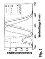
- FIG. 2 shows the normalized standard spectral functions of the interference filters 21, 22 and 23 for the respective coordinate of the selected CIE color space.
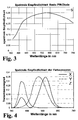
- the spectral transmission of the interference filters 21, 22 and 23 is so dimensioned that the product of basic sensitivity S (shown in FIG. 3 for Si diodes according to PIN technology) and transmission characteristic of the respective interference filter 21, 22 or 23 is proportional to the desired normal spectral value curve ,
- the product of basic sensitivity S and filter transmission X, Y, Z is always used as the overall spectral sensitivity of the color sensor, as shown in FIG. 4 for a specific case (based on FIG. 3).
- the base material of the sensor chip 1 is equipped with Si diodes, which were manufactured in a specially adapted for the visual spectral range PIN diode technology and thus in their spectral sensitivity of the human eye are best approximated.
- the sensitivity curve of a PIN diode produced in this way is shown in FIG. 3.
- Ge or InGaAs diodes can also be used instead of Si diodes.
- FIG. 4 illustrates the overall spectral sensitivity distribution of the color sensor when the interference filter structure 2 with its three different interference filters 21, 22 and 23 for the X, Y and Z components on a sensor chip 1 according to the sensitivity function of FIG. 3 (eg In order to obtain the resulting transmission characteristics of the color sensor in the three coordinates of the color space shown in Figure 4, the interference filters 21, 22 and 23 are suitable to vary with respect to the layer thicknesses of the alternating layers Associated system of interference filters 21, 22, 23 is indicated for example in Fig. 7a (X-filter), 7b (Y-filter) and Fig. 7c (Z-filter) for the coordinates of the color space.
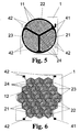
- FIG. 5 shows a variant of the sensor chip 1 for a selectively measurable color sensor.
- the black area is the cathode 41 of the complete triple element of the color sensor.
- the white areas represent the anodes 42 of the three partial areas 11 of the photosensor, from which the occurring photocurrents are derived as measured values.
- Striped subarea 11 is intended, in the selected case, to have the X-transmission function (as shown in FIG. 2) generated by interference filter 21, while checkered and brick-patterned subarea 11 show the Y and Z transmission functions of interference filters 22 and 23, respectively (as shown in FIG 2) symbolize.
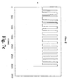
- FIG. 6 A special design of the color sensor according to the invention for planar Color measurements are shown in Fig. 6 in a plan view of the sensor chip 1.
- the sensor chip 1 has a plurality of honeycomb-shaped triple elements 12, each of which three Si diodes with the different interference filters 21, 22 and 23 exist.
- the triple elements 12 are arranged to each other so that an interference filter 21, 22 or 23 no common edge with the same interference filter 21, 22 or 23 has each of the adjacent triple elements 12. This results in a regular structure on the entire sensor chip 1, which is capable of one Measuring the uniformity of a color impression of a surface.
- the sequence of alternating layers of the X-filter of the X-filter of the color sensor (partial surface 11 for the spectral function of the red sensitivity of the human eye is particularly variable with respect to the layer thicknesses.) This is due to the likewise complicated course
- the spectral transmission function approximated according to the solid line for the X coordinate of the color space in Fig. 2.
- the interference filter 22 indicated in Fig. 7b is designed as a switching system for the Y filter of the color sensor
- the interference filter 23 for the blue "color perception of the color sensor" approximated by the Z filter shown in Fig.
- the layer thickness d of the individual interference filters 21, 22 and 23 was set at less than 4 ⁇ m and preferably set at 3000 nm ⁇ d ⁇ 3500 nm.
- the interference filters 21, 22 and 23 computed by computer-aided optimization (the required to approximate the standard spectral function of the eye transmission functions) have between 30 and 40 layers. In the example shown in FIGS.
- the X-filter 35, the Y-filter 37 and the Z-filter 34 comprise alternating layers of TiO 2 and SiO 2 .
- the interference filters 21, 22 and 23 thus calculated can be applied directly to the Si diodes of the sensor chip 1 by plasma-assisted coating (after application of a passivation layer). On the other hand, they can also be applied to a glass substrate or manufactured with lift-off techniques and subsequently adjusted over the silicon chip in order to avoid wasting valuable semiconductor material if layer tolerances are not met for the complicated interference filter structure 2.
- Luminous Color stimuli are therefore advantageous to reinterpret as body color by e.g. whose emission spectrum scales to values ⁇ 1 and thus as a transmission spectrum an equivalent filter.
- Scaling i. an alignment of the sensor channels to each other (i.e., a white balance the signals / measured values of the sub-areas 11 of the three-channel photosensor to the standard spectral functions of the human eye) is self-evident essential. Apart from this scaling should under normal conditions no correction the measured values are required.
- a narrowband color stimulus can be simulated as a bandpass spectral interference filter, with a typical measure of the spectral bandwidth of a conventional 15 nm interference filter can be assumed.
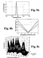
- Fig. 8a shows the spectral transmission (or remission) of such an object for a centroid wavelength of 555 nm.
- the transmittance is set at 15 nm spectral width and a 1 / e drop and examined with variable centroid wavelength.
- the filter curve is shifted from -12 nm to +12 nm in 0.5 nm steps for error estimation and determined for each shift ⁇ E of the emission spectrum of target color and measured color in CIELAB space, depending on from the centroid wavelength of the target transmission.
- the maximum value of ⁇ E over all centroid wavelengths was plotted as a function of the filter curve displacement in FIG. 8b.
- the overall result of the error calculation is illustrated in Figure 8c as a function of the centroid wavelength and the shift of the filter function of the model target in the CIELAB space in the event that only the X filter function has been shifted.
- the measured color deviation for each centroid wavelength is approximately proportional to the amount of filter curve shift.
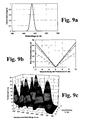
- LED's can be set by specifying a transmission filter with a filter width of 40 nm, because the spectral behavior of typical LEDs is good is approximated. It is thus replaced by an object with corresponding Transmission failed.
- the transition area of the ramp function is 50 nm Width specified and its center position (hereinafter called ramp position), which is shown in Fig. 10a at 555 nm Fig. 10a, over the entire visible spectrum varied.
- FIG. 11a Another example is a flatter ramp function (low color contrast) examined according to Fig. 11a, again by the ramp position with a Transition range of 50 nm over the entire visible spectrum varies.
- the maximum color deviation ⁇ E in the CIELAB space is thereby characterized in that because of the reduced color saturation according to FIG Significantly reduce sentimental color deviations.
- Fig. 11c shows about the same qualitative behavior as Fig. 10c, but small amounts of error.
- the standard spectral value of x j is multiplicatively composed of the filter transmission T j (setpoint) and the basic sensitivity S of the sensor.
- ⁇ can be represented as the product of the light source spectrum ⁇ B and the spectral reflectance ⁇ .
- the color sensor according to the invention should still be able to achieve a clear leap in quality.
- the local linear correction is still capable of further development and can become even more profound in order to create sensor specifications with peak parameters in a large number of applications.
- the optimization criterion has to be determined carefully according to the measurement tasks to be solved. The results so far, however, already clearly show that a linear approach is sufficient for the single errors as well as the linear superposition. Because of the linearity approach thus established, it is possible to calculate the maximum manufacturing tolerances for the filter systems for approaching the standard spectral function of the human eye from given maximum measurement errors and to set them during production.
Landscapes
- Physics & Mathematics (AREA)
- Spectroscopy & Molecular Physics (AREA)
- General Physics & Mathematics (AREA)
- Spectrometry And Color Measurement (AREA)
Abstract
Die Erfindung betrifft einen Photosensor zur Farbmessung auf Basis von drei Spektralanteilen, insbesondere für die hochgenaue Farbmessung bei der Prüfung und Sicherung der Farbkonstanz von technischen Oberflächen und beliebigen Konsumgütern.The invention relates to a photosensor for color measurement based on three Spectral components, in particular for the high-precision color measurement in the test and Ensuring the color consistency of technical surfaces and any Consumer goods.
Die Aufgabe, eine neue Möglichkeit zur Farbmessung auf Basis eines
Dreibereichsverfahrens mit durch vorgelagerte unterschiedlich spektralempfindliche
Interferenzfilter erzeugten Farbmesswerten zu finden, die mit einfachen Mitteln eine
nahezu normgerechte Echtfarben-Messung ohne aufwendige Bezugslichtkalibrierung
gestattet, wird erfindungsgemäß gelöst, indem der Photosensor aus mindestens drei
mit unterschiedlichen auf die X-, Y- und Z-Spektralcharakteristik des menschlichen
Auges angepassten Interferenzfiltern bedeckten Teilflächen besteht, die jeweils
flächengleich und kreissektorförmig gleichverteilt um ein Zentrum mit
dazwischenliegenden passivierten Stegen angeordnet sind, und jede Teilfläche mit
einem in seiner Transmissionscharakteristik über die Wellenlänge des spektral zu
messenden Lichts der Empfindlichkeit des menschlichen Auges angepasstes
Interferenzfilter versehen ist, wobei die durchgelassenen Spektralanteile der
Interferenzfilter jeweils den Normspektralwertfunktionen des menschlichen Auges in
Farbkoordinaten des Farbraumes angenähert sind.

Description
Die Erfindung betrifft einen Photosensor zur Farbmessung auf Basis von drei Spektralanteilen, zu deren Erfassung der Sensorchip durch eine vorgelagerte Interferenzfilterstruktur drei unterschiedlich empfindliche Teilflächen aufweist, wobei die Teilflächen Messwerte bereitstellen, die in einem geeigneten Farbraum in Farbwerte umgesetzt werden, insbesondere für die hochgenauen Farbmessung (Punktmessung) bei der Prüfung und Sicherung der Farbkonstanz von technischen Oberflächen und beliebigen Konsumgütern.The invention relates to a photosensor for color measurement based on three Spectral components, for detecting the sensor chip by an upstream Interference filter structure has three different sensitive faces, wherein the subareas provide measurements that are in a suitable color space in Color values are implemented, especially for the high-precision color measurement (Point measurement) when testing and ensuring the color consistency of technical Surfaces and any consumer goods.
Im Zuge der allgemeinen technisch-technologischen Entwicklung haben sich auch die Anforderungen an einfache Einzelfarbsensoren, Farbsensorarrays und Farbkameras stark erhöht. Das hängt einerseits mit gestiegenen Erwartungen an das Design (vor allem Farbkonstanz) von industriellen Produkten und Konsumgütern und andererseits mit den ständig steigenden Qualitätsansprüchen bei der Mensch-Maschine-Kommunikation zusammen. Insbesondere letzterer Teilbereich der Technik ist durch ständig steigende Ansprüche der modernen Medien allgemein und des e-Commerce im Besonderen geprägt und muss bei einer Vielzahl unterschiedlicher Display- und Druckersysteme befriedigende Ergebnisse liefern. Deshalb wird bei applikationsspezifisch jeweils unterschiedlichen Anforderungen an die Genauigkeit der Drang nach normgerechter Farmessung ("True Colour") immer größer.In the course of general technical and technological development, the Requirements for simple single-color sensors, color sensor arrays and color cameras greatly increased. This depends on the one hand with increased expectations of the design (before all color constancy) of industrial products and consumer goods and on the other hand with the ever-increasing quality demands in human-machine communication together. In particular, the latter part of the art is through ever-increasing demands of modern media in general and e-commerce in particular coined and must with a multiplicity of different display and Printer systems provide satisfactory results. That's why application-specific different requirements for accuracy the urge to standard-compliant Farmessung ("True Color") ever larger.
Für die Farbmessung sind grundsätzlich drei unterschiedliche Methoden bekannt geworden:
- Vergleichsverfahren,
- Spektralverfahren und
- Dreibereichsverfahren.
- Comparison method,
- Spectral method and
- Three area method.
Aus Aufwands- und Kostengründen wird vornehmlich auf das Dreibereichsverfahren zurückgegriffen, obwohl dieses mit wesentlichen Einschränkungen verbunden ist, weil damit im Ergebnis wellenlängenintegrale Farbwerte erhalten werden, die nur für die verwendete Beleuchtung gültig sind. So lassen sich Metamerie-Indizes beispielsweise nur durch eine Abfolge von Messungen bei unterschiedlichen Beleuchtungen (Bezugslichtart und Testlichtart), die stets physisch vorhanden sein müssen, bestimmen. For expense and cost reasons is mainly on the tri-range method although this is associated with significant limitations, because as a result, wavelength-integral color values are obtained which are only valid for the lighting used is valid. This is how metamerism indexes can be for example, only by a sequence of measurements at different Illuminations (reference light and test light) that are always physically present need to determine.
Das grundlegende Prinzip eines spektral angepassten Halbleiter-Sensors ist bereits aus
der US 3,996,461 bekannt. Dort wird für einen Silizium-Photosensor ein optisches
Dünnschichtfilter auf Basis eines Interferenz-Mehrschichtsystems beschrieben, um die
Empfindlichkeit des Sensors auf die spektrale Empfindlichkeit des menschlichen
Auges zu beschränken. Das Interferenzfilter besteht aus einem Wechselschichtsystem
von reinen λ/4-Schichten für die Wellenlängen von λ = 550 nm, 780 nm und
1000 nm. Dabei sind die hochbrechenden Schichten aus Titanoxid und die
niedrigbrechenden Siliziumoxid. Das resultierende Filtersystem entspricht einer
Y-Charakteristik der spektralen Empfindlichkeitskurve des menschlichen Auges, ohne
dass damit eine spektral selektive Auflösung des Farbspektrums im Sinne der
Zuordnung von Farbwerten oder Normspektralfarben möglich ist, da die
Filterschichten nicht strukturiert sind, sondern auf mehrere Sensorelemente zugleich
aufgetragen werden.
In der US 5,246,803 sind strukturierte dichroitische Filter für festkörperelektronische
Bildsensoren offenbart, die durch abwechselnde Ablagerung auf die
Sensoroberfläche oder eine Glasschicht erfolgen. Dabei wurde die wechselnde
Abscheidung von SiO2- und TiO2-Schichten unter Vakuumbedingungen und niedriger
Temperatur zur Erzeugung von Farbfiltern beschrieben, wobei die spektrale
Charakteristik der Filter durch die Anzahl und Dicke der Schichten gesteuert und die
Formung und Ablagerung der Schichten beliebig oft wiederholt wird, um Rot-, Grünund
Blaufilter zu erzeugen. Gemäß US 5,246,803 wird z.B. bei einem
Wechselschicht-Filterstapel für das Blaufilter ein Durchlassbereich ("on-band region"
mit ca. 80 % Transmission) mit 400-500 nm erzeugt, während der Reflexionsbereich
("off-band region" mit weniger als 5 % Transmission) zwischen 500 und 700 nm
beträgt.
Nachteilig an dieser Lösung ist, dass es sich um reine Bandpass- bzw. Kantenfilter
handelt, so dass Punktmessungen bei schmalbandigen Farbreizen im off-band-Bereich
der Farbfilter regelmäßig zur Messung von verfälschten Farbwerten führen
oder eine spezielle Bezugslichtkalibrierung benötigen.The basic principle of a spectrally adjusted semiconductor sensor is already known from US 3,996,461. There, a thin film optical filter based on an interference multilayer system is described for a silicon photosensor, in order to limit the sensitivity of the sensor to the spectral sensitivity of the human eye. The interference filter consists of an alternating layer system of pure λ / 4 layers for the wavelengths of λ = 550 nm, 780 nm and 1000 nm. The high refractive index layers are made of titanium oxide and the low refractive index silicon oxide. The resulting filter system corresponds to a Y characteristic of the spectral sensitivity curve of the human eye, without allowing a spectrally selective resolution of the color spectrum in terms of the assignment of color values or standard spectral colors, since the filter layers are not structured, but are applied to several sensor elements at the same time.
US 5,246,803 discloses structured dichroic filters for solid state electronic image sensors which are made by alternately depositing on the sensor surface or a glass layer. Here, the varying deposition of SiO 2 and TiO 2 layers under vacuum conditions and low temperature for the production of color filters was described, the spectral characteristic of the filter controlled by the number and thickness of the layers and the formation and deposition of the layers is repeated as often to create red, green and blue filters. According to US Pat. No. 5,246,803, for example, in the case of an alternating-layer filter stack for the blue filter, an on-band region with about 80% transmission is generated at 400-500 nm, while the reflection region (off-band region with less than 5 % Transmission) is between 500 and 700 nm.
A disadvantage of this solution is that it is pure bandpass or edge filters, so that point measurements with narrow-band color stimuli in the off-band region of the color filter regularly lead to the measurement of falsified color values or require a special reference light calibration.
Der Erfindung liegt die Aufgabe zugrunde, eine neue Möglichkeit zur Farbmessung auf Basis eines Dreibereichsverfahrens mit drei, durch vorgelagerte unterschiedlich spektral selektive Interferenzfilter erzeugten Farbmesswerten zu finden, die mit einfachen Mitteln eine nahezu normgerechte Echtfarben-Messung ohne aufwendige Bezugslichtkalibrierung gestattet.The invention is based on the object, a new way of color measurement on the basis of a tristimulus method with three, different by upstream to find spectrally selective interference filters generated colorimetric measurements using simple means an almost standard true color measurement without consuming Reference light calibration allowed.
Erfindungsgemäß wird die Aufgabe bei einem Photosensor zur Farbmessung auf Basis von drei Spektralanteilen, zu deren Erfassung ein Sensorchip mindestens drei durch eine vorgelagerte Interferenzfilterstruktur unterschiedlich empfindliche Teilflächen aufweist, wobei die Interferenzfilterstruktur drei unterschiedliche Wechselschichtsysteme aus Siliziumdioxid und Titandioxid zum selektiven Transmittieren einfallenden Lichts in die unterschiedlichen Teilflächen des Sensorchips beinhaltet und die Teilflächen Messwerte bereitstellen, dadurch gelöst, dass der Photosensor drei mit unterschiedlichen auf die Spektralcharakteristik des menschlichen Auges angepassten Interferenzfiltern bedeckte Teilflächen aufweist, die jeweils kreissektorförmig um einen Zentralpunkt verteilt mit dazwischenliegenden passiven Stegen angeordnet sind, und dass jedes Interferenzfilter ein in seiner Transmissionscharakteristik über die Wellenlänge des spektral zu messenden Lichts der Empfindlichkeit des menschlichen Auges derart angepasst ist, dass das Produkt aus Basisempfindlichkeit der Teilflächen des Photosensors und Transmission des Interferenzfilters proportional dem Normalspektralwertverlauf des menschlichen Auges für die betreffende Koordinate des Farbraumes ist, so dass die durchgelassenen Spektralanteile in den Teilflächen Messwerte erzeugen, die bei einfacher Skalierung zueinander im Farbraum in Spektralfarbwerte umsetzbar sind.According to the invention the task is in a photosensor for color measurement Basis of three spectral components, for their detection a sensor chip at least three different sensitivity through an upstream interference filter structure Partial surfaces, wherein the interference filter structure three different Alternating layer systems of silicon dioxide and titanium dioxide for selective Transmitting incident light in the different sub-areas of the sensor chip contains and the subareas provide readings, solved by the Photosensor three with different on the spectral characteristics of the human eye adapted interference filters covered partial surfaces, the each circular-sector-shaped distributed around a central point with intermediate passive webs are arranged, and that each interference filter is one in his Transmission characteristic over the wavelength of the spectrally measured light the sensitivity of the human eye is adjusted so that the product from basic sensitivity of the partial surfaces of the photosensor and transmission of the Interference filter proportional to the normal spectral value of the human Eye is for the relevant coordinate of the color space, so the transmitted spectral components in the sub-areas produce measured values that at simple scaling to each other in the color space in spectral color values can be implemented.
Dadurch dass das Produkt aus der Basisempfindlichkeit des Photosensors (Photodiode) und Transmissionscharakteristik jedes Interferenzfilters proportional dem Normalspektralwertverlauf des menschlichen Auges für die betreffende Koordinate des Farbraumes ist, entspricht die spektrale Empfindlichkeit des erfindungsgemäßen Photosensors nahezu exakt dem Farbempfinden des menschlichen Auges und ermöglicht die Separation von Farbunterschieden in gleicher und besserer Qualität wie das menschliche Auge. By making the product of the basic sensitivity of the photosensor (Photodiode) and transmission characteristic of each interference filter proportional to Normal spectral value course of the human eye for the relevant coordinate of the color space corresponds to the spectral sensitivity of the invention Photosensors almost exactly the color perception of the human eye and allows the separation of color differences in the same and better quality like the human eye.
Bei der technologischen Umsetzung eines als computersimuliertes
Wechselschichtsystem (mit alternierenden Schichten aus TiO2 und SiO2
unterschiedlicher Schichtdicken) ideal angepassten Interferenzfilters für die jeweilige
Farbkoordinate im Farbraum wird die Transmissionscharakteristik jedes
Interferenzfilters zweckmäßig mit einer Toleranz der Schichtdicken von weniger als
2 % hergestellt.
Da die Einhaltung deutlich geringerer Schichtdickentoleranzen (etwa < 1 %) aus
technologischer Sicht derzeit unrealistisch ist, wird - soweit das die Genauigkeit der
Farbmessung für die gewünschte Anwendung erfordert - zur Kompensation der
herstellungsbedingten Schichtdickenabweichungen eine lineare Korrektur der von
den Teilflächen ausgegebenen Messwerte vorgenommen. Das kann zum einen durch
eine globale Matrizierung zur Korrektur der ausgegebenen Messwerte für den
gesamten Farbraum und zum anderen - bei gesteigerten Genauigkeitsanforderungen,
z.B. zur Ausgabe von genauen Farbmaßzahlen - durch lineare
Korrektur der ausgegebenen Messwerte mittels lokaler Matrizierung geeigneter
Tetraederbereiche des Farbraumes geschehen.In the technological implementation of a computer simulated alternating-layer system (with alternating layers of TiO 2 and SiO 2 of different layer thicknesses) ideally matched interference filter for the respective color coordinate in the color space, the transmission characteristic of each interference filter is advantageously prepared with a tolerance of the layer thicknesses of less than 2%.
Since adherence to significantly lower layer thickness tolerances (for example <1%) is currently unrealistic from a technological point of view, a linear correction of the measured values output by the partial surfaces is undertaken to compensate for the production-related layer thickness deviations, as far as the accuracy of the color measurement requires for the desired application. On the one hand, this can be done by global matrixing for correcting the output measured values for the entire color space and, on the other hand, with increased accuracy requirements, eg for output of accurate colorimetric values, by linear correction of the output measured values by means of local matrixing of suitable tetrahedron regions of the color space.
Für die Realisierung einer kompakten Bauweise des Farbsensors ist es von Vorteil,
dass die Interferenzfilter direkt auf den Halbleiterdioden des Sensorchip aufgebracht
sind. Dabei werden die Interferenzfilter vorzugsweise direkt auf Siliziumdioden des
Sensorchip aufgebracht. Am besten sind die Si-Dioden dazu in einer speziell für den
visuellen Spektralbereich angepassten PIN-Dioden-Technologie hergestellt worden,
um bereits eine vorteilhafte Basisempfindlichkeit der Si-Dioden des gesamten Sensorchip
zu erreichen. In diesem Fall ergibt sich der besondere Zusatzvorteil, dass die Alterung und
Temperaturabhängigkeit des Gesamtsystems aus Photodiode und Interferenzfilter
vernachlässigbar sind. Weiterhin ist es für bestimmte Genauigkeitsklassen sogar möglich,
die Photoströme als ausgelesene Farbmesswerte direkt in einen genormten Farbraum zu
überführen.
Die Interferenzfilter können aber auch zweckmäßig auf Si-Dioden aufgebracht
werden, die in einer auf den visuellen Spektralbereich angepassten CMOS-Technologie
hergestellt wurden. For the realization of a compact design of the color sensor, it is advantageous that the interference filter are applied directly to the semiconductor diodes of the sensor chip. In this case, the interference filters are preferably applied directly to silicon diodes of the sensor chip. The Si diodes are best produced in a specially adapted for the visual spectral range PIN diode technology to already achieve an advantageous basic sensitivity of the Si diodes of the entire sensor chip. In this case, there is the particular additional advantage that the aging and temperature dependence of the entire system of photodiode and interference filter are negligible. Furthermore, it is even possible for certain accuracy classes to convert the photocurrents as read-out color measurement values directly into a standardized color space.
However, the interference filters can also be suitably applied to Si diodes which have been produced in a CMOS technology adapted to the visual spectral range.
Weiterhin können die Interferenzfilter aber auch auf einem Sensorchip mit
Germaniumdioden oder mit Dioden auf Basis von InGaAs aufgebracht sein.
Unter technologischen Aspekten der einzuhaltenden Schichtdickentoleranzen, d.h.
um bei Toleranzüberschreitungen nicht den gesamten Sensorchip zu verderben,
können die Interferenzfilter über den Si-Dioden (Teilflächen) des Sensorchip auch
vorteilhaft auf einer separaten Glasplatte aufgebracht werden oder auch durch
Anwendung von Lift-Off-Techniken eingesetzt werden.Furthermore, the interference filters can also be applied to a sensor chip with germanium diodes or with diodes based on InGaAs.
Under technological aspects of the layer thickness tolerances to be complied with, ie in order not to spoil the entire sensor chip in the event of tolerance violations, the interference filters can also be advantageously applied over the Si diodes (partial surfaces) of the sensor chip on a separate glass plate or by using lift-off techniques become.
Für Remissionsmessungen von Oberflächen, bei denen eine gleichmäßige
Ausleuchtung des Photosensors gegeben ist, sind die aufgrund aufgebrachter
Interferenzfilter unterschiedlich empfindlichen Teilflächen auf dem Sensorchip
vorzugsweise als Kreissegment (Kreisflächendrittel) geformt und um einen
Zentralpunkt gleichverteilt angeordnet.
Eine weitere Ausgestaltung, mit der eine Skalierung der spektralen Charakteristiken
der Teilflächen des Photosensors auf die Empfindlichkeitsverteilung des Auges
mindestens teilweise hardwaremäßig realisierbar ist, besteht darin, dass die mit den
angepassten Interferenzfiltern bedeckten, unterschiedlich empfindlichen Teilflächen
auf dem Sensorchip als Kreisflächensektoren unterschiedlichen Flächeninhalts um
einen Zentralpunkt angeordnet sind, wobei die unterschiedlichen Flächeninhalte
darauf abgestimmt sind, dass eine niedrigere Basisempfindlichkeit einer Teilfläche, die
aufgrund eingeschränkter Wellenlängen-Transmission des zugehörigen
Interferenzfilters zustande kommt, durch einen entsprechend größeren Flächeninhalt
der Teilfläche des Photosensors kompensiert wird.For remission measurements of surfaces in which a uniform illumination of the photosensor is given, the differently sensitive partial surfaces on the sensor chip are preferably formed as a circle segment (circular area third) due to applied interference filters and arranged uniformly distributed about a central point.
Another embodiment, with which a scaling of the spectral characteristics of the partial surfaces of the photosensor to the sensitivity distribution of the eye is at least partially realizable hardware, is that the covered with the matched interference filters, different sensitive sub-areas on the sensor chip as a circular area sectors of different surface area around a central point are arranged, wherein the different surface areas are tuned to that a lower base sensitivity of a partial surface, which comes about due to limited wavelength transmission of the associated interference filter, is compensated by a correspondingly larger surface area of the partial surface of the photosensor.
Als weitere zweckmäßige Form der Teilflächen des Photosensors sind die mit
unterschiedlichen Interferenzfiltern beschichteten Teilflächen in Form von Rhomben
mit 120°-Winkel gleichverteilt um einen Zentralpunkt angeordnet, so dass sie als ein
Tripelfarbsegment ein regelmäßiges Sechseck bilden.
Diese sechseckigen Tripelfarbsegmente lassen sich vorteilhafte jeweils um eine
Vielzahl von Zentralpunkten mit gleichen Stegen und gleichverteilt geordnet auf dem
Sensorchip aufbringen, so dass die Tripelfarbsegmente eine Wabenstruktur bilden,
wobei Teilflächen gleicher spektraler Empfindlichkeit keine benachbarten
Seitenkanten miteinander haben.As a further expedient form of the partial surfaces of the photosensor, the partial surfaces coated with different interference filters are distributed uniformly around a central point in the form of rhombi with a 120 ° angle, so that they form a regular hexagon as a triple color segment.
Advantageously, these hexagonal triple color segments can be arranged on the sensor chip so as to form a honeycomb structure around a plurality of central points with the same webs and uniformly distributed, with subareas of the same spectral sensitivity having no adjacent side edges with one another.
Mit dem erfindungsgemäßen Photosensor ist es möglich, Farbmessungen auf Basis eines Dreibereichsverfahrens mit drei, durch unterschiedlich spektral selektive Interferenzfilter erzeugten Farbmesswerten zu realisieren, die mittels an die Normspektralfunktion des menschlichen Auges angepasster Interferenzfilter eine nahezu normgerechte Echtfarben-Messung ohne aufwendige Bezugslichtkalibrierung gestattet. Im Ergebnis können Farbunterschiede in mit dem menschlichen Auge vergleichbarer Qualität separiert werden. Weiterhin sind die gemessenen Photoströme der drei Teilflächen des Sensors für bestimmte Genauigkeitsklassen der Farbmessung direkt in genormte Farbräume überführbar. Mit der Erfindung lassen sich preiswerte Farbsensoren realisieren und in leistungsfähige kompakte Farbmessgeräte integrieren.With the photosensor according to the invention it is possible to color measurements based a tristimulus method with three, by different spectrally selective Interference filter to produce generated color readings, by means of the Standard spectral function of the human eye adapted interference filter Near-standard true color measurement without complex reference light calibration allowed. As a result, color differences in with the human eye of comparable quality are separated. Furthermore, the measured Photocurrents of the three subareas of the sensor for certain accuracy classes of the Color measurement directly convertible into standardized color spaces. Leave with the invention Realize inexpensive color sensors and in powerful compact Integrate colorimeters.
Die Erfindung soll nachstehend anhand von Ausführungsbeispielen näher erläutert werden. Die Zeichnungen zeigen:
- Fig. 1:
- eine Gestaltung des erfindungsgemäßen Photosensors zur Farbmessung in schematischer Schnittdarstellung,
- Fig. 2:
- eine Prinzipdarstellung der Transmissionsfunktionen des erfindungsgemäßen Dreifiltersystems für die unterschiedlichen Koordinaten im CIE-Farbraum als Adaption an die Normalspektralwertfunktion des menschlichen Auges,
- Fig. 3:
- ein Schema der Basisempfindlichkeit des Sensormaterials,
- Fig. 4:
- eine Darstellung des idealen Transmissionsgrades der Interferenzfilter unter Berücksichtigung der Basisempfindlichkeit des Photosensors,
- Fig. 5:
- eine erste Variante des erfindungsgemäßen Farbsensors (Draufsicht) als Einzelsensor mit drei durch unterschiedliche Interferenzfilterfunktionen verschieden empfindlichen Teilflächen,
- Fig. 6:
- eine zweite Ausgestaltung des erfindungsgemäßen Farbsensors als Mehrelementsensor mit einer Vielzahl von Tripelfarbelementen in einer Wabenstruktur,
- Fig. 7a:
- ein optimiertes Interferenzfilter aus einem SiO2- und TiO2-Wechselschicht-system für die adaptierte Rotempfindlichkeitsfunktion des Photosensors als X-Koordinate des Farbraumes,
- Fig. 7b:
- ein optimiertes SiO2/TiO2-Interferenzfilter für die adaptierte Grünempfindlichkeitsfunktion des Photosensors (Y-Koordinate im Farbraum),
- Fig. 7c:
- ein optimiertes SiO2/TiO2-Interferenzfilter für die adaptierte Blauempfindlichkeitsfunktion des Photosensors (Z-Koordinate im Farbraum),
- Fig. 8a:
- die spektrale Transmission (oder Remission) eines schmalbandigen Modelltargets
mit 15 nm spektraler Breite und 1/e-Abfall für eine Schwerpunktwellenlänge von 555 nm, - Fig. 8b:
- den Maximalwert von ΔE über alle Schwerpunktwellenlängen als Funktion der Filterkurvenverschiebung des Modelltargets nach Fig. 8a,
- Fig. 8c:
- das Gesamtresultat der Fehlerrechnung als Funktion der Schwerpunktwellenlänge und der Verschiebung der Filterfunktion des Modelltargets nach Fig. 8a,
- Fig. 9a:
- die spektrale Transmission (oder Remission)
eines Modelltargets mit 40 nm spektraler Breite und 1/e-Abfall für die Schwerpunktwellenlänge von 555 nm, - Fig. 9b:
- den Maximalwert von ΔE über alle Schwerpunktwellenlängen als Funktion der Filterkurvenverschiebung des Modelltargets nach Fig. 9a,
- Fig. 9c:
- das Gesamtresultat der Fehlerrechnung als Funktion der Schwerpunktwellenlänge und der Verschiebung der Filterfunktion des Modelltargets nach Fig. 9a,
- Fig. 10a:
- Remissionsgrad eines Modelltargets mit rampenförmigem Remissionsverlauf
mit einer Breite des
Übergangsbereiches von 50 nm, - Fig. 10b:
- Maximale Farbabweichung für Modelltargets gemäß Fig. 10a als Funktion der Verschiebung der X-Filterkurve,
- Fig. 10c:
- Gesamtergebnis der Fehlerrechnung bei Verschiebung der X-Filterfunktion für Targets,
- Fig. 11 a:
- Remissionsgrad eines Modelltargets mit rampenförmigem Remissionsverlauf
mit einer Breite des
Übergangsbereiches von 50 nm bei geringerem Farbkontrast, - Fig. 11
- b:Maximale Farbabweichung für Modelltargets nach Fig. 11 a als Funktion der Verschiebung der X-Filterkurve,
- Fig. 11 c:
- Gesamtergebnis der Fehlerrechnung bei Verschiebung der X-Filterfunktion für Targets gemäß Fig. 11 a,
- Fig. 12a:
- Maximale Farbabweichung für 15 nm breite Farbreize als Funktion der Verschiebung der X-Filterkurve, ermittelt für herkömmliche Sensoren mit Drei-Bandpass-Filtersystem (hier: MSC3-Sensor der Fa. MAZeT, DE),
- Fig. 12b:
- Gesamtergebnis der Fehlerrechnung bei Verschiebung der X-Filterfunktion für 15 nm Spektralbreite des Farbreizes (gemäß Fig. 8a), ermittelt für herkömmliche Sensoren mit Drei-Bandpass-Filtersystem (MSC3-Sensoren).
- Fig. 1:
- a design of the photosensor according to the invention for color measurement in a schematic sectional view,
- Fig. 2:
- a schematic diagram of the transmission functions of the three-filter system according to the invention for the different coordinates in the CIE color space as an adaptation to the normal spectral value function of the human eye,
- 3:
- a schematic of the basic sensitivity of the sensor material,
- 4:
- a representation of the ideal transmittance of the interference filter taking into account the basic sensitivity of the photosensor,
- Fig. 5:
- a first variant of the color sensor according to the invention (top view) as a single sensor with three differently sensitive by different interference filter functions faces,
- Fig. 6:
- a second embodiment of the color sensor according to the invention as a multi-element sensor with a plurality of triple color elements in a honeycomb structure,
- Fig. 7a:
- an optimized interference filter made of a SiO 2 and TiO 2 alternating-layer system for the adapted red-sensitivity function of the photosensor as X-coordinate of the color space,
- Fig. 7b:
- an optimized SiO 2 / TiO 2 interference filter for the adapted green sensitivity function of the photosensor (Y-coordinate in the color space),
- Fig. 7c:
- an optimized SiO 2 / TiO 2 interference filter for the adapted blue sensitivity function of the photosensor (Z-coordinate in the color space),
- 8a:
- the spectral transmission (or remission) of a narrowband model target with 15 nm spectral width and 1 / e drop for a centroid wavelength of 555 nm,
- 8b:
- the maximum value of ΔE over all centroid wavelengths as a function of the filter curve displacement of the model target of Fig. 8a,
- 8c:
- the overall result of the error calculation as a function of the centroid wavelength and the shift of the filter function of the model target of FIG. 8a,
- Fig. 9a:
- the spectral transmission (or remission) of a model target with 40 nm spectral width and 1 / e drop for the centroid wavelength of 555 nm,
- Fig. 9b:
- the maximum value of ΔE over all centroid wavelengths as a function of the filter curve displacement of the model target of Fig. 9a,
- Fig. 9c:
- the overall result of the error calculation as a function of the centroid wavelength and the shift of the filter function of the model target of FIG. 9a,
- Fig. 10a:
- Remission degree of a model target with a ramped remission curve with a width of the transition region of 50 nm,
- Fig. 10b:
- Maximum color deviation for model targets according to FIG. 10a as a function of the shift of the X-filter curve,
- Fig. 10c:
- Overall result of the error calculation when shifting the X-filter function for targets,
- Fig. 11 a:
- Remission degree of a model target with a ramped remission curve with a width of the transition region of 50 nm with a lower color contrast,
- Fig. 11
- b: maximum color deviation for model targets according to FIG. 11 a as a function of the shift of the X-filter curve,
- Fig. 11c:
- Overall result of the error calculation with displacement of the X-filter function for targets according to FIG. 11 a,
- Fig. 12a:
- Maximum color deviation for 15 nm wide color stimuli as a function of the shift of the X-filter curve, determined for conventional sensors with three band pass filter system (here: MSC3 sensor from MAZeT, DE),
- Fig. 12b:
- Overall result of the error calculation with displacement of the X-filter function for 15 nm spectral width of the color stimulus (according to FIG. 8a), determined for conventional sensors with three-band-pass filter system (MSC3 sensors).
Der erfindungsgemäße Farbsensor besteht in seinem Grundaufbau - wie in Fig. 1
schematisch dargestellt - aus einem Sensorchip 1 mit photoempfindlichen Teilflächen
11, und einer Interferenzfilterstruktur 2 mit spektral unterschiedlich empfindlichen
Interferenzfiltern 21, 22, und 23 (nur in Fig. 5 und 6 bezeichnet) einem Gehäuse 3
mit Eintrittsfenster 31 und darauf vorhandener Infrarotfilterschicht 32 sowie den
Anschlusselektroden 4.
Das Interferenzfiltersystem 2 weist jeweils als Tripelelement drei unterschiedlich
dimensionierte Wechselschichtsysteme aus Siliziumdioxid- und Titandioxidschichten
auf, deren spektrale Transmission an die Normspektralfunktionen des menschlichen
Auges angepasst sind. Fig. 2 zeigt die normierten Normspektralfunktionen der
Interferenzfilter 21, 22 und 23 für die jeweilige Koordinate des gewählten CIE-Farbraumes.
Die spektrale Transmission der Interferenzfilter 21, 22 und 23 wird so bemessen, dass
das Produkt aus Basisempfindlichkeit S (in Fig. 3 dargestellt für Si-Dioden nach PIN-Technologie)
und Transmissionscharakteristik des jeweiligen Interferenzfilters 21, 22
oder 23 proportional dem gewünschten Normalspektralwertverlauf ist. Als spektrale
Gesamtempfindlichkeit des Farbsensors wird also stets das Produkt aus
Basisempfindlichkeit S und Filtertransmission X, Y, Z verwendet, wie es in Fig. 4 für
einen speziellen Fall (auf Basis von Fig. 3) dargestellt ist.
Im Folgenden wird - ohne Beschränkung der Allgemeinheit - angenommen, dass das
Basismaterial des Sensorchip 1 mit Si-Dioden bestückt ist, die in einer speziell für den
visuellen Spektralbereich angepassten PIN-Dioden-Technologie hergestellt wurden
und somit in ihrer spektralen Empfindlichkeit der des menschlichen Auges am besten
angenähert sind. Die Empfindlichkeitskurve einer so gefertigten PIN-Diode zeigt in
Fig. 3. Bei ähnlich geformter Basisempfindlichkeit S können anstelle von Si-Dioden
auch Ge- oder InGaAs-Dioden verwendet werden.The color sensor according to the invention consists in its basic structure - as shown schematically in FIG. 1 - of a
The
The spectral transmission of the interference filters 21, 22 and 23 is so dimensioned that the product of basic sensitivity S (shown in FIG. 3 for Si diodes according to PIN technology) and transmission characteristic of the
Fig. 4 stellt die gesamte spektrale Empfindlichkeitsverteilung des Farbsensors dar,
wenn die Interferenzfilterstruktur 2 mit ihren drei unterschiedlichen Interferenzfiltern
21, 22 und 23 für die X-, Y- und Z-Komponenten auf einem Sensorchip 1 gemäß der
Empfindlichkeitsfunktion von Fig. 3 (z.B. auf Basis von PIN-Dioden aufgebracht ist.
Um die in Fig. 4 gezeigten resultierenden Transmissionsverläufe des Farbsensors in
den drei Koordinaten des Farbraumes zu erhalten, sind die Interferenzfilter 21, 22
und 23 geeignet bezüglich der Schichtdicken der Wechselschichten zu variieren. Ein
solches geeignet optimiertes zusammengehöriges System von Interferenzfiltern 21,
22, 23 ist z.B. in den Fig. 7a (X-Filter), 7b (Y-Filter) und Fig. 7c (Z-Filter) für die
Koordinaten des Farbraumes angegeben.
Fig. 5 zeigt eine Variante des Sensorchip 1 für ein punktuell messfähigen Farbsensor.
Dabei ist die schwarze Fläche die Katode 41 des kompletten Tripelelements des
Farbsensors. Die weißen Bereiche stellen die Anoden 42 der drei Teilflächen 11 des
Photosensors dar, von denen die auftretenden Photoströme als Messwerte abgeleitet
werden. Die gestreifte Teilfläche 11 soll in dem gewählten Fall die mit dem
Interferenzfilter 21 erzeugte X-Transmissionsfunktion (gemäß Fig. 2) aufweisen,
während die karierte und die ziegelgemusterte Teilfläche 11 die Y- bzw. Z-Transmissionsfunktionen
der Interferenzfilter 22 und 23 (nach Fig. 2) symbolisieren.4 illustrates the overall spectral sensitivity distribution of the color sensor when the
FIG. 5 shows a variant of the
Eine besondere Gestaltung des erfindungsgemäßen Farbsensors für flächige
Farbmessungen ist in Fig. 6 in einer Draufsicht auf den Sensorchip 1 dargestellt. Hier
weist der Sensorchip 1 mehrere wabenförmige Tripelelemente 12 auf, die jeweils aus
drei Si-Dioden mit den unterschiedlichen Interferenzfilter 21, 22 und 23 bestehen.
Die Tripelelemente 12 sind dabei so zueinander angeordnet, dass ein Interferenzfilter
21, 22 oder 23 keine gemeinsame Kante mit demselben Interferenzfilter 21, 22 oder
23 jedes der benachbarten Tripelelemente 12 hat. Dadurch ergibt sich eine
regelmäßige Struktur auf dem gesamten Sensorchip 1, die in der Lage ist, eine
Messung der Gleichmäßigkeit eines Farbeindrucks einer Oberfläche vorzunehmen.A special design of the color sensor according to the invention for planar
Color measurements are shown in Fig. 6 in a plan view of the
Wie Fig. 7a zu entnommen werden kann, ist die Abfolge der alternierenden
Schichten des Wechselschichtsystems des X-Filters des Farbsensors (Teilfläche 11 für
die anzupassende Spektralfunktion der Rotempfindlichkeit des menschlichen Auges
besonders wechselhaft bezüglich der Schichtdicken. Das hat seine Ursachen in dem
gleichfalls komplizierten Verlauf der anzunähernden spektralen Transmissionsfunktion,
die gemäß der durchgezogenen Linie für die X-Koordinate des Farbraumes
in Fig. 2 angeglichen wurde. Etwas regelmäßiger ist das Interferenzfilter 22,
angegeben in Fig. 7b als Wechselschichtsystem für das Y-Filter des Farbsensors,
gestaltet, das dem grünen Farbempfinden des menschlichen Auges zugeordnet ist.
Demgegenüber vermittelt das Interferenzfilter 23 für das blaue "Farbempfinden des
Farbsensors", angenähert durch das in Fig. 7c angegebene Z-Filter, eine nahezu
regelmäßige Struktur des Wechselschichtsystems aus SiO2 und TiO2. die Optimierung
der gesamten Filterstruktur 2 aus den Interferenzfiltern 21, 22 und 23 wurde vom
Standpunkt einer begrenzten Gesamtschichtdicke betrieben, um eine möglichst hohe
Gesamttransmission der Interferenzfilterstruktur 2 zu erhalten. Deshalb wurde die
Schichtdicke d der einzelnen Interferenzfilter 21, 22 und 23 mit kleiner 4 µm
angesetzt und vorzugsweise mit 3000 nm ≤ d ≤ 3500 nm vorgegeben.
Die durch rechnergestützte Optimierung (der zur Annäherung der Normspektralfunktion
des Auges geforderten Transmissionsfunktionen) errechneten
Interferenzfilter 21, 22 und 23 weisen zwischen 30 und 40 Schichten auf. Im in Fig.
7a-c dargestellten Beispiel enthält das X-Filter 35, das Y-Filter 37 und das Z-Filter 34
alternierende Schichten aus TiO2 und SiO2.
Die so berechneten Interferenzfilter 21, 22 und 23 können zum einen durch
plasmagestütztes Beschichten (nach Auftrag einer Passivierungsschicht) direkt auf die
Si-Dioden des Sensorchip 1 aufgebracht werden. Andererseits können sie - zur
Vermeidung der Vergeudung von wertvollem Halbleitermaterial bei nicht eingehalten
Schichttoleranzen für die komplizierten Interferenzfilterstruktur 2 - aber auch auf ein
Glassubstrat aufgetragen oder mit Lift-Off-Techniken hergestellt und nachträglich
über dem Siliziumchip justiert werden. As can be seen from Fig. 7a, the sequence of alternating layers of the X-filter of the X-filter of the color sensor (
The interference filters 21, 22 and 23 computed by computer-aided optimization (the required to approximate the standard spectral function of the eye transmission functions) have between 30 and 40 layers. In the example shown in FIGS. 7a-c, the X-filter 35, the Y-filter 37 and the Z-filter 34 comprise alternating layers of TiO 2 and SiO 2 .
The interference filters 21, 22 and 23 thus calculated can be applied directly to the Si diodes of the
Die weiteren Ausführungen beschäftigen sich mit der erzielbaren Genauigkeit der
Farbmessung für eine erfindungsgemäß einzuhaltende Toleranz der Schichtdicken
von weniger 2%. Es wurde herausgefunden, dass eine variierte Schichtdicke in dieser
Größenordnung im Wesentlichen lediglich eine Verschiebung der theoretisch
berechneten Filterfunktion um maximal ± 12 nm (bei 600 nm) bewirkt. Diese Verschiebung
infolge von Schichtdickenvarianzen ist zusätzlich in Fig. 2 als gestrichelte
Linie für die X-Filterfunktion eingezeichnet worden, diese Auswirkung bei einer
Schichtdickenabweichung des Interferenzfilters 21 darzustellen.
Bei den folgenden Betrachtungen ist stets die Umsetzung der Messwerte des
Dreibereichs-Photosensors in einen normierten CIE-Farbraum vorgesehen. Ein
Überblick über die Eigenschaften von CIE-Farbräumen kann den Vorschriften der ISO
7724 (bzw. DIN 5033) entnommen werden. Zur Fehlerabschätzung wird - ohne
Beschränkung der Anwendung der Erfindung mit anderen CIE-Farbräumen - der
LAB-Farbraum genutzt. Man beachte, dass im CIELAB-Raum aufgrund der
Nichtlinearität keine sinnvolle Normierung der Farbwerte wie im XYZ-Raum möglich
ist.The further explanations are concerned with the achievable accuracy of the color measurement for a tolerance of the layer thicknesses of less than 2% to be maintained according to the invention. It has been found that a varied layer thickness on this scale essentially causes only a shift of the theoretically calculated filter function by a maximum of ± 12 nm (at 600 nm). This shift due to layer thickness variances has been additionally drawn in FIG. 2 as a dashed line for the X filter function, to illustrate this effect in the case of a layer thickness deviation of the
In the following considerations, the conversion of the measured values of the tristimulus photosensor into a normalized CIE color space is always provided. An overview of the properties of CIE color spaces can be found in the regulations of ISO 7724 (or DIN 5033). For error estimation - without limiting the application of the invention with other CIE color spaces - the LAB color space is used. Note that in the CIELAB space due to the non-linearity no meaningful normalization of the color values as in XYZ space is possible.
Zur Darstellung eines selbstleuchtenden Objekts benötigt man dessen Leuchtdichte in Bezug auf die Hintergrundleuchtdichte. Es fällt jedoch ohne weitere Information schwer, einen repräsentativen Wert für die Leuchtdichte vorzugeben. Daher werden häufig nur remittierte und transmittierte Farbreize angenommen. Selbstleuchtende Farbreize sind deshalb vorteilhaft als Körperfarbe umzudeuten, indem man z.B. dessen Emissionsspektrum auf Werte ≥ 1 skaliert und somit als Transmissionsspektrum eines äquivalenten Filters interpretiert.To display a self-luminous object you need its luminance in Reference to the background luminance. It falls, however, without further information hard to give a representative value for the luminance. Therefore, be often only remitted and transmitted color stimuli assumed. Luminous Color stimuli are therefore advantageous to reinterpret as body color by e.g. whose emission spectrum scales to values ≥ 1 and thus as a transmission spectrum an equivalent filter.
Eine Skalierung, d.h. ein Abgleich der Sensorkanäle zueinander (d.h. ein Weißabgleich der Signale/Messwerte der Teilflächen 11 des dreikanaligen Photosensors auf die Normspektralfunktionen des menschlichen Auges), ist selbstverständlich unerlässlich. Außer dieser Skalierung soll unter Normalbedingungen keine Korrektur der Messwerte erforderlich sein. Scaling, i. an alignment of the sensor channels to each other (i.e., a white balance the signals / measured values of the sub-areas 11 of the three-channel photosensor to the standard spectral functions of the human eye) is self-evident essential. Apart from this scaling should under normal conditions no correction the measured values are required.
Ein schmalbandiger Farbreiz kann als spektrales Bandpass-Interferenzfilter simuliert
werden, wobei ein typisches Maß für die spektrale Bandbreite eines herkömmlichen
Interferenzfilters mit 15 nm angenommen werden kann.
Fig. 8a zeigt die spektrale Transmission (oder Remission) eines solchen Objekts für
eine Schwerpunktwellenlänge von 555 nm. Für ein solches Modelltarget wird der
Transmissionsgrad mit 15 nm spektraler Breite und einem 1/e-Abfall angesetzt und
mit variabler Schwerpunktwellenlänge untersucht. Gegenüber einer Solllage von
555 nm wird zur Fehlerabschätzung die Filterkurve von -12 nm bis +12 nm
in 0,5 nm-Schritten verschoben und dabei für jede Verschiebung ΔE des
Emissionsspektrums von Sollfarbe und gemessener Farbe im CIELAB-Raum ermittelt,
und zwar in Abhängigkeit von der Schwerpunktwellenlänge der Solltransmission. Der
Maximalwert von ΔE über alle Schwerpunktwellenlängen wurde als Funktion der
Filterkurvenverschiebung in Fig. 8b eingetragen.
Das Gesamtresultat der Fehlerrechnung ist in Fig. 8c als Funktion der Schwerpunktwellenlänge
und der Verschiebung der Filterfunktion des Modelltargets im CIELAB-Raum
für den Fall veranschaulicht, dass nur die X-Filterfunktion verschoben wurde.
Im Ergebnis ist die gemessene Farbabweichung für jede Schwerpunktwellenlänge
etwa proportional zum Betrag der Filterkurvenverschiebung. Für Y und Z-Verschiebungen
ergeben sich qualitativ gleichwertige Ergebnisse. Lokale Maxima der
Farbabweichungen, die in der Größenordnung mit dem absoluten Maximum
vergleichbar sind, haben ihre Schwerpunktwellenlänge etwa an den Wendepunkten
der Filterfunktion. Diese Aussage ist für transmittierende und reflektierende Objekte
anwendbar, wobei maximale Helligkeit angenommen wurde, da der CIELAB-Raum
größere Helligkeit mit größerem Farbabstand bewertet.A narrowband color stimulus can be simulated as a bandpass spectral interference filter, with a typical measure of the spectral bandwidth of a conventional 15 nm interference filter can be assumed.
Fig. 8a shows the spectral transmission (or remission) of such an object for a centroid wavelength of 555 nm. For such a model target, the transmittance is set at 15 nm spectral width and a 1 / e drop and examined with variable centroid wavelength. Compared to a target position of 555 nm, the filter curve is shifted from -12 nm to +12 nm in 0.5 nm steps for error estimation and determined for each shift ΔE of the emission spectrum of target color and measured color in CIELAB space, depending on from the centroid wavelength of the target transmission. The maximum value of ΔE over all centroid wavelengths was plotted as a function of the filter curve displacement in FIG. 8b.
The overall result of the error calculation is illustrated in Figure 8c as a function of the centroid wavelength and the shift of the filter function of the model target in the CIELAB space in the event that only the X filter function has been shifted.
As a result, the measured color deviation for each centroid wavelength is approximately proportional to the amount of filter curve shift. Y and Z shifts give qualitatively equivalent results. Local maxima of the color deviations, which are comparable in magnitude to the absolute maximum, have their center of gravity wavelength approximately at the inflection points of the filter function. This statement is applicable to transmissive and reflective objects, assuming maximum brightness, because the CIELAB space evaluates greater brightness with greater color separation.
LED's können durch Vorgabe eines Transmissionsfilters mit einer Filterbreite von 40 nm simuliert werden, weil damit das spektrale Verhalten von typischen LED's gut angenähert wird. Es wird also ersatzweise von einem Objekt mit entsprechender Transmission ausgegangen. LED's can be set by specifying a transmission filter with a filter width of 40 nm, because the spectral behavior of typical LEDs is good is approximated. It is thus replaced by an object with corresponding Transmission failed.
Das Ergebnis für ein solches Modelltarget mit 40 nm spektraler Breite ist dem der Filterfunktion mit 15 nm Bandbreite sehr ähnlich, wie Fig. 9a zu entnehmen ist. Somit kann unterstellt werden, dass die Farbverschiebung - zumindest im dazwischen liegenden Spektralintervall - nahezu unabhängig von der spektralen Breite des Modelltargets ist und bei gegebenen Testobjekt praktisch linear zur Verschiebung der X-, Y- oder Z-Filterkurve ist. Damit ist eine einfache Rückrechnung von vorgegebenen Farbmessfehlern auf die sekundären Toleranzen möglich, da innerhalb der linearen Näherung gearbeitet werden kann.The result for such a model target with 40 nm spectral width is that of the Filter function with 15 nm bandwidth very similar, as shown in FIG. 9a. Consequently can be assumed that the color shift - at least in between lying spectral interval - almost independent of the spectral width of the Model Targets is and for a given test object practically linear to the shift of X, Y or Z filter curve. This is a simple retroactive calculation of predetermined Color measurement errors on the secondary tolerances possible because within the linear Approximation can be worked.
Bei einer Dickentoleranz von ± 2 % je Schicht des Filtersystems kann - wie Variationsrechnungen ergeben - eine maximale Kurvenverschiebung von ca. ± 12 nm auftreten. Bei einer solchen Verschiebung werden schon deutlich spürbare Farbabweichungen gemessen, wie aus Fig. 8b und 9b ersichtlich. Um schmalbandige Farbreize mit hoher Genauigkeit messen zu können, wäre eine Verringerung der Fertigungstoleranzen etwa um den Faktor 10 erforderlich. Da diese Forderung jedoch unrealistisch ist, muss - wenn eine hochgenaue Farbmessung das Ziel ist - bei fehlerhaften Filterkurven linear korrigiert werden (Matrizierung, möglichst lokal).With a thickness tolerance of ± 2% per layer of the filter system can - like Variational calculations yield a maximum curve displacement of approx. ± 12 nm occur. With such a shift are already clearly noticeable Color deviations measured, as shown in Fig. 8b and 9b. To narrowband To be able to measure color stimuli with high accuracy would be a reduction of Manufacturing tolerances required by a factor of about 10. However, this requirement is unrealistic, must - if a highly accurate color measurement is the goal - with incorrect filter curves are corrected linearly (matrixing, if possible locally).
Bei standardisierten Testfarben kann die spektrale Remission häufig durch eine "steigende" Rampenfunktion angenähert werden, wobei die Rampenfunktion gekennzeichnet ist durch:
- ein Intervall mit konstanter minimaler Remission,
- ein folgendes Intervall mit positivem Anstieg und
- ein anschließendes Intervall mit konstanter maximaler Remission.
- an interval with constant minimal remission,
- a following interval with positive increase and
- a subsequent interval with constant maximum remission.
Für dieses dritte Beispiel wird unter Verwendung der Normallichtart D65 vorausgesetzt, dass außer einer Skalierung keine Korrektur der Messwerte vorgenommen wird. Der Übergangsbereich der Rampenfunktion wird mit 50 nm Breite vorgegeben und seine Mittenposition (nachfolgend Rampenposition genannt), die in Fig. 10a bei 555 nm Fig. 10a gezeigt ist, über das gesamte sichtbare Spektrum variiert. For this third example, using the normal density D65 provided that, apart from a scaling, no correction of the measured values is made. The transition area of the ramp function is 50 nm Width specified and its center position (hereinafter called ramp position), which is shown in Fig. 10a at 555 nm Fig. 10a, over the entire visible spectrum varied.
Es zeigt sich wiederum eine maximale Farbabweichung ΔE im CIELAB-Raum bei
Verschiebung der X-, Y- und Z-Filterkurve. Im Gegensatz zu schmalbandigen
Farbreizen tritt hier für jede X-Filter-Verschiebung lediglich ein deutliches Maximum
der Farbabweichung bei ca. 630 nm auf, wie es Fig. 10b erkennbar ist. Bei Y-Filter-Verschiebung
liegt das Maximum bei 605 nm und bei Z-Filter-Verschiebung bei
475 nm (nicht als separat dargestellt). Dies entspricht wieder den Wendepunkten der
fallenden Kanten der idealen Filterkurven (aus Fig. 2). Bezüglich des X-Filters gibt es
nur zur rechten fallenden Flanke des X-Filters einen passenden Höchstwert, wie es
aus Fig. 10c zu entnehmen ist.
Insgesamt ist die Farbabweichung wesentlich geringer als bei schmalbandigen
Farbreizen.Again, there is a maximum color deviation ΔE in the CIELAB space when the X, Y and Z filter curves are shifted. In contrast to narrow-band color stimuli, only a clear maximum of the color deviation at approximately 630 nm occurs here for each X-filter shift, as can be seen in FIG. 10b. At Y-filter shift, the maximum is at 605 nm and at Z-filter shift at 475 nm (not shown separately). This again corresponds to the inflection points of the falling edges of the ideal filter curves (from FIG. 2). With respect to the X-filter, only the right falling edge of the X-filter has a suitable maximum value, as can be seen from FIG. 10c.
Overall, the color deviation is much lower than with narrowband color stimuli.
Als weiteres Beispiel wird eine flachere Rampenfunktion (geringer Farbkontrast) gemäß Fig. 11a untersucht, indem erneut die Rampenposition mit einem Übergangsbereich von 50 nm über das gesamte sichtbare Spektrum variiert. In diesem Fall ist die maximale Farbabweichung ΔE im CIELAB-Raum dadurch gekennzeichnet, dass sich wegen der reduzierten Farbsättigung gemäß Fig. 11 b die empfindungsadaptierten Farbabweichungen deutlich verringern. Fig. 11 c zeigt dazu etwa dasselbe qualitative Verhalten wie Fig. 10c, aber kleiner Beträge der Fehler.Another example is a flatter ramp function (low color contrast) examined according to Fig. 11a, again by the ramp position with a Transition range of 50 nm over the entire visible spectrum varies. In In this case, the maximum color deviation ΔE in the CIELAB space is thereby characterized in that because of the reduced color saturation according to FIG Significantly reduce sentimental color deviations. Fig. 11c shows about the same qualitative behavior as Fig. 10c, but small amounts of error.
Schlussfolgernd kann also festgestellt werden, dass sich die empfundenen Farbabweichungen mit zunehmender Bandbreite und abnehmender Sättigung verringern. Im relevanten Bereich (±12 nm) von auftretenden Verschiebungen der idealen Filterfunktion, der infolge herstellungsbedingter Abweichungen der Schichtdicken der Interferenzfilter 21, 22 und 23 von den theoretisch berechneten Schichtdicken d einkalkuliert werden muss, kann zwischen Filterkurvenverschiebung und Farbabweichung eine lineare Abhängigkeit angenommen werden. Damit ergibt sich die Möglichkeit der Beschränkung auf eine lineare (differentielle) Toleranzrechnung, soweit dies aus Gründen der geforderten Genauigkeit der Farbmessung erforderlich ist. In conclusion, it can be said that the perceived ones Color deviations with increasing bandwidth and decreasing saturation reduce. In the relevant range (± 12 nm) of occurring shifts of the ideal Filter function due to production - related deviations of the layer thicknesses of Interference filters 21, 22 and 23 of the theoretically calculated layer thicknesses d can be calculated between filter curve shift and Color deviation can be assumed to be a linear dependence. This results the possibility of limiting to a linear (differential) tolerance calculation, as far as necessary for reasons of the required accuracy of the color measurement is.
In den obigen Beispielen wurden die zu erwartenden Messfehler anhand
ausgewählter Remissions- bzw. Transmissionsverläufe analysiert. Die Frage, welche
Farbreizfunktion zu maximalen Messfehlern führt (kritischer Remissionsverlauf), ist
damit noch nicht beantwortet. Eine echte, von der Applikation unabhängige Worst-Case-Betrachtung
ist jedoch nur auf der Grundlage der kritischen Farbreize möglich.
Die Theorie dazu ist anspruchsvoll und wird im Folgenden nur grob skizziert. Für die
Verschiebung ΔE eines Farbwertes im CIELAB-Raum gilt

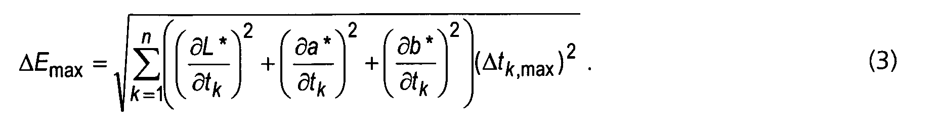
Die CIELAB-Farbkoordinaten sind differenzierbare Funktionen der Normfarbwerte X,
Y, Z. Schreibt man ausnahmsweise X = X 1, Y = X 2, Z = X 3, so erhält man aus
Gleichung (3)
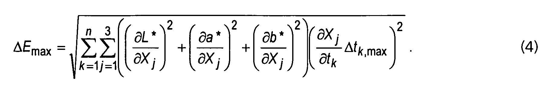


Der Lösungsansatz besteht darin, die gesuchte Funktion β zu diskretisieren, indem
man das Integral in Gleichung (6) durch die Näherungssumme ersetzt. Dadurch wird
die Variationsaufgabe in ein nichtlineares Optimierungsproblem mit z.B. 81 freien
Parametern überführt (bei einem Stützstellenabstand von 5 nm). Ohne a-priori-Wissen
ist jedoch eine solche Aufgabe nur lokal durch Iterationsverfahren lösbar. Es
bleibt somit ungewiss, ob eine der lokalen Lösungen mit dem globalen Optimum
übereinstimmt. Es ist jedoch abhebbar, dass sich ein kritischer Remissionsverlauf nicht
für obige Modellfunktionen (schmalbandige und rampenförmige Farbreize) oder
einfache Kombinationen davon ergibt.
Vorstehend wurden die Messergebnisse eines erfindungsgemäßen
Dreibereichssensors, der die oben beschriebenen Anforderungen (Aufgabe) erfüllt,
anhand von Testfarbreizen simuliert, die durch einige praktisch relevante
Modellfunktionen (Modelltargets) erzeugt wurden.
Jeder dieser Testfarbreize enthielt einen freien Parameter, der praktisch kontinuierlich
variiert wurde (Schwerpunktwellenlänge bzw. Rampenposition).
Als grundsätzliche Methode wurde die Simulation und farbmetrische Bewertung der
Messergebnisse bei Variation von geeignet gewählten Modellparametern verwendet.
Im Vordergrund stand dabei die Fehleranalyse bei Variation (herstellungsbedingten
Abweichungen) der Filterfunktionen, nicht die Korrektur von systematischen
Messfehlern.The CIELAB color coordinates are differentiable functions of the standard color values X, Y, Z. If one exceptionally writes X = X 1 , Y = X 2 , Z = X 3 , one obtains from equation (3)
The approach is to discretize the desired function β by replacing the integral in equation (6) with the approximation sum. This converts the variational task into a nonlinear optimization problem with, for example, 81 free parameters (at a interpolation point distance of 5 nm). Without a priori knowledge, however, such a task can only be solved locally by iterative methods. It thus remains uncertain whether one of the local solutions matches the global optimum. However, it is possible to claim that a critical remission course does not result for the above model functions (narrow-band and ramp-shaped color stimuli) or simple combinations thereof.
In the foregoing, the measurement results of a tristimulus sensor according to the present invention satisfying the above-described requirements (task) were simulated by using test color stimuli generated by some practically relevant model functions (model targets).
Each of these test color stimuli contained a free parameter that was varied virtually continuously (centroid wavelength or ramp position, respectively).
As a fundamental method, the simulation and colorimetric evaluation of the measurement results was used with variation of suitably chosen model parameters. The focus was on the error analysis with variation (production-related deviations) of the filter functions, not the correction of systematic measurement errors.
Zu den systematischen Messfehlern des erfindungsgemäßen Sensors ist kurz
anzumerken, dass diese in ungünstigen Fällen eine Größenordnung zu hoch sind für
eine präzise Messung von Farbwerten ("true color"). Eine Verringerung der Schichtdickentoleranzen
des Interferenzfilters auf etwa 1 % ändert an dieser Situation nur
sehr wenig. Daher ist zusätzlich eine exemplarabhängige Korrektur der Messfehler
durch Software sinnvoll. Es ist festzustellen, dass mit einer globalen linearen
Korrektur (Matrizierung) bereits deutliche Verbesserungen erreicht werden.
Falls eine gleichmäßige und genaue Korrektur des gesamten Farbraumes erforderlich
ist, kann man bei Bedarf auf eine lokale lineare Korrektur zurückgreifen. Darunter
versteht man die Zerlegung des Farbraumes in Tetraeder und Anwendung einer
getrennten linearen Korrektur auf jeden Tetraeder, wobei an den Grenzflächen
stetige Übergangsbedingungen einzuhalten sind. Dieser (pessimistische) Ansatz hat
jedoch nur für sehr anspruchsvolle Farbmessaufgaben seine Bedeutung, nämlich
wenn mit der Annäherung der XYZ-Kurven die Ausgabe genauer Farbmaßzahlen zu
realisieren ist.
Die Simulationen zur Auswirkung von Farbverschiebungen bei den erfindungsgemäßen
Filterfunktionen X, Y, Z der Interferenzfilter 21, 22 und 23 zeigen aber im
direkten Vergleich zu den "alten" Filterfunktionen (Rot-, Grün-, Blau-Bandpässe) von
Dreibereichssensoren, dass der erfindungsgemäße Photosensor zur Farbmessung
auch ohne Messwertkorrektur zu deutlich geringeren Messfehlern führt als bisherige
Farbsensoren mit herkömmlichen RGB-Filtersystemen. Wenn man z.B. die
Farbabweichung mit herkömmlichen Filtern in der gleichen Weise berechnet, erhält
man Ergebnisse, die deutlich größere Maximalabweichungen ergeben (Fig. 12a und
12b im Vergleich zu den erfindungsgemäßen Ergebnissen nach den Fig. 8b und 8c).Concerning the systematic measurement errors of the sensor according to the invention, it should be noted briefly that in unfavorable cases they are one order of magnitude too high for a precise measurement of color values ("true color"). A reduction of the layer thickness tolerances of the interference filter to about 1% changes very little in this situation. Therefore, a copy-dependent correction of measurement errors by software is also useful. It can be seen that with a global linear correction (matrixing) already significant improvements are achieved.
If a uniform and accurate correction of the entire color space is required, one can resort to a local linear correction if necessary. This is the decomposition of the color space into tetrahedrons and the application of a separate linear correction to each tetrahedron, whereby constant transition conditions must be observed at the interfaces. However, this (pessimistic) approach has its meaning only for very demanding color measurement tasks, namely, if the output of exact color scales can be achieved with the approximation of the XYZ curves.
The simulations of the effect of color shifts in the inventive filter functions X, Y, Z of the interference filters 21, 22 and 23 show, however, in direct comparison to the "old" filter functions (red, green, blue bandpasses) of tristimulus sensors that the invention Photosensor for color measurement even without measurement correction leads to significantly lower measurement errors than previous color sensors with conventional RGB filter systems. For example, by calculating the color deviation with conventional filters in the same way, one obtains results which give much larger maximum deviations (Figures 12a and 12b compared to the results according to the invention of Figures 8b and 8c).
Aus Fig. 12a ist abzulesen, dass die maximalen Fehler bei der bisherigen Filtervariante
die erfindungsgemäße Lösung um etwa den Faktor 4 übersteigen. Noch
aussagekräftiger ist aber der Vergleich von Fig. 12b mit Fig. 8c. Während für die
betrachteten schmalbandigen Reize bei den neuen Filterkurven ein Fehler von 20 nur
für extreme Toleranzen und nur in einem relativ kleinen Bereich von
Mittenwellenlängen überschritten wird, sinken die Fehler bei den bisherigen
Filterkurven nur bei ca. 580 nm und bei 625 nm in sehr kleinen Frequenzintervallen
unter diesen Wert ab. Auch die maximalen Abweichungen der neuen Filtervariante,
die quasi nur bei 8 speziellen Messsituationen (Verschiebung, Wellenlänge) auftreten,
werden für schmalbandige Reize nahezu immer wesentlich übertroffen. Obwohl
wegen der unendlichen Vielfalt möglicher spektraler Reize allgemeine quantitative
Aussagen schwer fallen, dürfte mit dem erfindungsgemäßen Farbsensor trotzdem ein
klarer Qualitätssprung gelungen sein. Die lokale lineare Korrektur ist noch
weiterentwicklungsfähig und kann noch tiefgründiger werden, um in einer Vielzahl
von Anwendungsfällen Sensorspezifikationen mit Spitzenparametern zu erstellen.
Anhand der bisher ausgewählten und weiterer Modellfarbreize kann weiterhin
simuliert werden, wie sich die Qualität der Messergebnisse durch globale lineare
Korrektur verbessern lassen. Hierbei ist das Optimierungskriterium sorgfältig nach den
zu lösenden Messaufgaben festzulegen.
Die bisherigen Ergebnisse zeigen jedoch bereits deutlich, dass ein linearer Ansatz für
die Einzelfehler sowie lineare Superposition ausreichen.
Aufgrund des so belegten Linearitätsansatzes ist es möglich, aus vorgegebenen
maximalen Messfehlern die maximalen Fertigungstoleranzen für die Filtersysteme zur
Annäherung an die Normspektralfunktion des menschlichen Auges zu berechnen und
bei der Fertigung einzustellen. It can be seen from FIG. 12a that the maximum errors in the previous filter variant exceed the solution according to the invention by a factor of approximately four. Even more meaningful, however, is the comparison of FIG. 12b with FIG. 8c. While for the considered narrow-band stimuli in the new filter curves an error of 20 only for extreme tolerances and only in a relatively small range of center wavelengths is exceeded, the errors in the previous filter curves fall only at about 580 nm and at 625 nm in very small Frequency intervals below this value. Also, the maximum deviations of the new filter variant, which occur almost only in 8 special measurement situations (displacement, wavelength), are almost always significantly exceeded for narrowband stimuli. Although general quantitative statements are difficult because of the infinite variety of possible spectral stimuli, the color sensor according to the invention should still be able to achieve a clear leap in quality. The local linear correction is still capable of further development and can become even more profound in order to create sensor specifications with peak parameters in a large number of applications. On the basis of the previously selected and further model color stimuli, it is also possible to simulate how the quality of the measurement results can be improved by global linear correction. Here, the optimization criterion has to be determined carefully according to the measurement tasks to be solved.
The results so far, however, already clearly show that a linear approach is sufficient for the single errors as well as the linear superposition.
Because of the linearity approach thus established, it is possible to calculate the maximum manufacturing tolerances for the filter systems for approaching the standard spectral function of the human eye from given maximum measurement errors and to set them during production.
- 11
- Sensorchipsensor chip
- 1111
- Teilflächensubareas
- 1212
- Tripelelementetriple elements
- 22
- InterferenzfilterstrukturInterference filter structure
- 2121
- Interferenzfilter (X)Interference filter (X)
- 2222
- Interferenzfilter (Y)Interference filter (Y)
- 2323
- Interferenzfilter (Z)Interference filter (Z)
- 2424
- StegeStege
- 33
- Gehäusecasing
- 3131
- Eintrittsfensterentrance window
- 3232
- Infrarotfilterinfrared filter
- 44
- Anschlusselektrodenterminal electrodes
- 4141
- Katodecathode
- 4242
- Anodenanodes
- SS
- Basisempfindlichkeitbased sensitivity
- X, Y, ZX, Y, Z
- Filterfunktionen/FiltercharakteristikenFilter functions / filter characteristics
Claims (16)
die Transmissionscharakteristik für jede unterschiedlich empfindliche Teilfläche des Sensorchip als computersimuliertes Wechselschichtsystem mit unterschiedlichen Schichtdicken aus TiO2 und SiO2 mit einer Toleranz der Schichtdicken von höchstens 2 % hergestellt ist.Photosensor according to claim 1, characterized in that
the transmission characteristic is produced for each differently sensitive partial area of the sensor chip as a computer-simulated alternating-layer system with different layer thicknesses of TiO 2 and SiO 2 with a tolerance of the layer thicknesses of at most 2%.
zur Kompensation von herstellungsbedingten Schichtdickenabweichungen eine Einrichtung zur linearen Korrektur der von den Teilflächen ausgegebenen Messwerte vorhanden ist. Photosensor according to claim 2, characterized in that
To compensate for production-related layer thickness deviations, there is a device for linear correction of the measured values output by the partial surfaces.
die Einrichtung zur linearen Korrektur der ausgegebenen Messwerte eine globale Matrizierung beinhaltet.Photosensor according to claim 3, characterized in that
the means for linearly correcting the output measured values includes global matrixing.
die Einrichtung zur linearen Korrektur der ausgegebenen Messwerte eine lokale Matrizierung für den gewählten Farbraum beinhaltet.Photosensor according to claim 3, characterized in that
the means for linear correction of the output measured values includes a local matrix for the selected color space.
die Interferenzfilter direkt auf Halbleiterdioden des Sensorchip aufgebracht sind.Photosensor according to claim 1, characterized in that
the interference filters are applied directly to semiconductor diodes of the sensor chip.
die Interferenzfilter direkt auf Siliziumdioden des Sensorchip aufgebracht sind.Photosensor according to claim 6, characterized in that
the interference filter are applied directly to silicon diodes of the sensor chip.
die Interferenzfilter auf Si-Dioden, die in einer speziell für den visuellen Spektralbereich angepassten PIN-Dioden-Technologie hergestellt wurden, aufgebracht sind.Photosensor according to claim 7, characterized in that
the interference filters on Si diodes, which were produced in a specially adapted for the visual spectral range PIN diode technology, are applied.
die Interferenzfilter auf Si-Dioden, die in einer speziell für den visuellen Spektralbereich angepassten CMOS-Technologie hergestellt wurden, aufgebracht sind.Photosensor according to claim 7, characterized in that
the interference filters on Si diodes, which were produced in a specially adapted for the visual spectral range CMOS technology, are applied.
die Interferenzfilter direkt auf einem Sensorchip mit Germaniumdioden aufgebracht sind.Photosensor according to claim 6, characterized in that
the interference filters are applied directly on a sensor chip with germanium diodes.
die Interferenzfilter direkt auf einem Sensorchip mit Dioden auf Basis von InGaAs aufgebracht sind. Photosensor according to claim 6, characterized in that
the interference filters are applied directly to a sensor chip with diodes based on InGaAs.
die Interferenzfilter über den Halbleiterdioden des Sensorchip auf einer separaten Glasplatte aufgebracht sind.Photosensor according to claim 1, characterized in that
the interference filters are applied over the semiconductor diodes of the sensor chip on a separate glass plate.
die mit angepassten Interferenzfiltern bedeckten, unterschiedlich empfindlichen Teilflächen auf dem Sensorchip als Kreisflächendrittel geformt und um einen Zentralpunkt angeordnet sind.Photosensor according to claim 1, characterized in that
the differently sensitive partial areas covered with matched interference filters are formed on the sensor chip as circular area thirds and arranged around a central point.
die mit den angepassten Interferenzfiltern bedeckten, unterschiedlich empfindlichen Teilflächen auf dem Sensorchip als Kreisflächensektoren unterschiedlichen Flächeninhalts um einen Zentralpunkt angeordnet sind, wobei die unterschiedlichen Flächeninhalte darauf abgestimmt sind, dass eine niedrigere Basisempfindlichkeit einer Teilfläche, die aufgrund eingeschränkter Wellenlängen-Transmission des zugehörigen Interferenzfilters zustande kommt, durch einen entsprechend größeren Flächeninhalt der Teilfläche des Photosensors kompensiert wird.Photosensor according to claim 1, characterized in that
the differently-sized partial areas covered with the matched interference filters are arranged on the sensor chip as circular area sectors of different area around a central point, the different areas being matched to a lower basic sensitivity of a partial area resulting from limited wavelength transmission of the associated interference filter, is compensated by a correspondingly larger surface area of the partial area of the photosensor.
die aufgrund angepasster Interferenzfilter unterschiedlich empfindlichen Teilflächen auf dem Sensorchip als Rhomben mit 120°-Winkel geformt und um einen Zentralpunkt angeordnet sind, so dass sie als ein Tripelfarbsegment ein regelmäßiges Sechseck bilden.Photosensor according to claim 1, characterized in that
the differently sensitive partial surfaces on the sensor chip are shaped as rhombs with a 120 ° angle and arranged around a central point so that they form a regular hexagon as a triple color segment due to matched interference filters.
die Tripelfarbsegmente jeweils um eine Vielzahl von Zentralpunkten mit gleichen Stegen und gleichverteilt geordnet auf dem Sensorchip aufgebracht sind, so dass die Tripelfarbsegmente wabenförmig angeordnet sind, wobei Teilflächen gleicher spektraler Empfindlichkeit keine benachbarten Seitenkanten miteinander haben.Photosensor according to claim 15, characterized in that
the triple color segments are respectively arranged on the sensor chip in such a way that they are arranged around a multiplicity of central points with identical webs and uniformly distributed, so that the triple color segments are arranged honeycomb-shaped, wherein subareas having the same spectral sensitivity have no adjacent side edges with one another.
Applications Claiming Priority (2)
| Application Number | Priority Date | Filing Date | Title |
|---|---|---|---|
| DE10346595 | 2003-10-02 | ||
| DE10346595 | 2003-10-02 |
Publications (3)
| Publication Number | Publication Date |
|---|---|
| EP1521069A2 true EP1521069A2 (en) | 2005-04-06 |
| EP1521069A3 EP1521069A3 (en) | 2007-01-24 |
| EP1521069B1 EP1521069B1 (en) | 2016-06-29 |
Family
ID=34306310
Family Applications (1)
| Application Number | Title | Priority Date | Filing Date |
|---|---|---|---|
| EP04023051.8A Expired - Lifetime EP1521069B1 (en) | 2003-10-02 | 2004-09-28 | Colorimeter for true colour measurement |
Country Status (2)
| Country | Link |
|---|---|
| US (1) | US7132644B2 (en) |
| EP (1) | EP1521069B1 (en) |
Cited By (5)
| Publication number | Priority date | Publication date | Assignee | Title |
|---|---|---|---|---|
| EP1857280A2 (en) | 2006-05-15 | 2007-11-21 | Koenig & Bauer Aktiengesellschaft | Rotary printing press with at least one inking unit and one inline colour measuring system |
| DE102006022530A1 (en) * | 2006-05-15 | 2007-11-22 | Koenig & Bauer Aktiengesellschaft | Rotary press comprises color deck and in-line inspection system, where sensors are formed as three discrete photographic areas has color sensor |
| WO2008065170A1 (en) | 2006-11-30 | 2008-06-05 | Osram Opto Semiconductors Gmbh | Radiation detector with an adjustable spectral sensitivity |
| WO2021185979A1 (en) * | 2020-03-19 | 2021-09-23 | ams Sensors Germany GmbH | Multichannel color sensor |
| US11199450B2 (en) | 2017-05-16 | 2021-12-14 | Ams Ag | Optical sensor and method for detecting electromagnetic radiation |
Families Citing this family (27)
| Publication number | Priority date | Publication date | Assignee | Title |
|---|---|---|---|---|
| DE10345410A1 (en) * | 2003-09-30 | 2005-05-04 | Osram Opto Semiconductors Gmbh | radiation detector |
| CN1938864B (en) * | 2004-03-31 | 2011-03-23 | 奥斯兰姆奥普托半导体有限责任公司 | Radiation detector |
| EP1812782A4 (en) * | 2004-11-16 | 2010-04-07 | Datacolor Holding Ag | Method for designing a colorimeter having integral cie color-matching filters |
| EP1812781A4 (en) * | 2004-11-17 | 2010-04-07 | Datacolor Holding Ag | Tristimulus colorimeter having integral dye filters |
| US20060146330A1 (en) * | 2005-01-04 | 2006-07-06 | Selvan Maniam | Color measurements of ambient light |
| US7580130B2 (en) * | 2005-03-23 | 2009-08-25 | Datacolor Holding Ag | Method for designing a colorimeter having integral illuminant-weighted CIE color-matching filters |
| US7474402B2 (en) * | 2005-03-23 | 2009-01-06 | Datacolor Holding Ag | Reflectance sensor for integral illuminant-weighted CIE color matching filters |
| EP1938063B1 (en) * | 2005-08-15 | 2011-12-21 | X-Rite Incorporated | Spectrophotometer with light guiding element |
| US8022632B2 (en) * | 2006-01-19 | 2011-09-20 | Koninklijke Philips Electronics N.V. | Color-controlled illumination device |
| US20070194212A1 (en) * | 2006-02-23 | 2007-08-23 | National Taiwan University | Ambient light photodetector |
| US7777915B2 (en) * | 2006-06-15 | 2010-08-17 | Eastman Kodak Company | Image control system and method |
| DE102006028672B3 (en) * | 2006-06-22 | 2007-10-18 | Infineon Technologies Ag | Single chip semiconductor-opto component e.g. optothyristor, for e.g. controlling infrared lighting system, has optodiode exhibiting relative spectral sensitivity, which is adapted to relative spectral sensitivity of eye |
| TW200832687A (en) * | 2007-01-30 | 2008-08-01 | Univ Nat Taiwan | Ambient light sensor |
| US7894064B2 (en) * | 2008-01-10 | 2011-02-22 | Hewlett-Packard Development Company, L.P. | Optical device for dispersing light |
| BRPI0909580B1 (en) * | 2008-05-28 | 2019-07-02 | Akzo Nobel Coatings International B. V. | METHOD OF DETERMINING A VARIANT MATCHING A STANDARD COLOR OF A REPAIR PAINT EQUALING THE EFFECT COLOR OF AN OBJECT TO BE REPAIR |
| US20100208266A1 (en) * | 2009-02-17 | 2010-08-19 | Colman Shannon | Tristimulus colorimeter having integral dye filters |
| JP2010258110A (en) * | 2009-04-22 | 2010-11-11 | Panasonic Corp | Solid-state image sensor |
| JP5696843B2 (en) * | 2011-03-23 | 2015-04-08 | 株式会社リコー | Method for evaluating electrophotographic overcoat composition, electrophotographic overcoat composition, electrophotographic forming method, and electrophotographic forming apparatus |
| KR20140007583A (en) * | 2012-07-09 | 2014-01-20 | 삼성디스플레이 주식회사 | Display panel detecting apparatus and method thereof |
| DE102013112906B4 (en) * | 2013-11-22 | 2020-08-20 | Schott Ag | Regulated colored light source |
| USD733599S1 (en) * | 2014-02-04 | 2015-07-07 | Hamamatsu Photonics K.K. | Spectrometer |
| US9823131B2 (en) * | 2015-06-02 | 2017-11-21 | X-Rite Switzerland GmbH | Sample target for improved accuracy of color measurements and color measurements using the same |
| EP3214483A1 (en) * | 2016-03-04 | 2017-09-06 | ESSILOR INTERNATIONAL (Compagnie Générale d'Optique) | Method for determining a value quantifying the effect of an optical filter on a parameter linked to an eye |
| ITUA20161497A1 (en) * | 2016-03-09 | 2017-09-09 | Ger Elettr S R L | DEVICE FOR DETECTION OF THE COLOR OF LEATHER AND AFFINE |
| KR102411607B1 (en) | 2017-10-13 | 2022-06-22 | 삼성디스플레이 주식회사 | Inspecting method of display panel |
| CN114846306A (en) * | 2019-12-26 | 2022-08-02 | ams传感器德国有限公司 | Integrated UV radiation sensor |
| CN114166345A (en) * | 2021-11-24 | 2022-03-11 | 江苏联格科技有限公司 | Circular array chip with spectral resolution |
Family Cites Families (10)
| Publication number | Priority date | Publication date | Assignee | Title |
|---|---|---|---|---|
| US3996461A (en) * | 1975-03-31 | 1976-12-07 | Texas Instruments Incorporated | Silicon photosensor with optical thin film filter |
| DE2920773A1 (en) * | 1979-05-22 | 1980-12-04 | Siemens Ag | Opto-electronic sensor circuit - has two separately adjusted photodiodes controlling integrated evaluation loop |
| US4562356A (en) * | 1983-11-28 | 1985-12-31 | Midac Corporation | Apparatus and method for photoluminescence analysis |
| US5246803A (en) * | 1990-07-23 | 1993-09-21 | Eastman Kodak Company | Patterned dichroic filters for solid state electronic image sensors |
| US5272518A (en) * | 1990-12-17 | 1993-12-21 | Hewlett-Packard Company | Colorimeter and calibration system |
| FR2701318B1 (en) * | 1993-02-09 | 1995-03-17 | Inst Francais Du Petrole | Improved device and method for optically measuring characteristics of a substance. |
| US6133954A (en) * | 1996-03-14 | 2000-10-17 | Tritech Microelectronics, Ltd. | Integrated circuit color chip with cells with integral color filters including triplets of photodiodes with each having integrated therewith transistors for reading from and writing to the photodiode and methods of manufacture and operation thereof |
| DE19638693C2 (en) * | 1996-09-20 | 1998-12-17 | Fraunhofer Ges Forschung | Photodetector and color filter using a photodetector |
| US6507401B1 (en) * | 1999-12-02 | 2003-01-14 | Aps Technology, Inc. | Apparatus and method for analyzing fluids |
| DE20315422U1 (en) * | 2003-10-02 | 2003-12-18 | Mazet Gmbh | Photosensor comprises partial surfaces covered with different interference filters suitable for the spectral characteristics of the human eye and each arranged around a central point having passive bars lying between them |
-
2004
- 2004-02-20 US US10/783,079 patent/US7132644B2/en not_active Expired - Lifetime
- 2004-09-28 EP EP04023051.8A patent/EP1521069B1/en not_active Expired - Lifetime
Cited By (14)
| Publication number | Priority date | Publication date | Assignee | Title |
|---|---|---|---|---|
| DE102006022530B4 (en) * | 2006-05-15 | 2014-06-26 | Koenig & Bauer Aktiengesellschaft | Web-fed rotary press with at least one inking unit and with an in-line inspection system |
| DE102006022530A1 (en) * | 2006-05-15 | 2007-11-22 | Koenig & Bauer Aktiengesellschaft | Rotary press comprises color deck and in-line inspection system, where sensors are formed as three discrete photographic areas has color sensor |
| DE102006022529A1 (en) * | 2006-05-15 | 2007-11-22 | Koenig & Bauer Aktiengesellschaft | Web-fed rotary press with at least one inking unit and with an in-line inspection system |
| EP1857280A3 (en) * | 2006-05-15 | 2011-04-06 | Koenig & Bauer Aktiengesellschaft | Rotary printing press with at least one inking unit and one inline colour measuring system |
| DE102006022529B4 (en) * | 2006-05-15 | 2009-05-20 | Koenig & Bauer Aktiengesellschaft | Web-fed rotary press with at least one inking unit and with an in-line inspection system |
| EP1857280A2 (en) | 2006-05-15 | 2007-11-21 | Koenig & Bauer Aktiengesellschaft | Rotary printing press with at least one inking unit and one inline colour measuring system |
| KR101430030B1 (en) * | 2006-11-30 | 2014-08-14 | 오스람 옵토 세미컨덕터스 게엠베하 | Radiation detector with an adjustable spectral sensitivity |
| US8274657B2 (en) | 2006-11-30 | 2012-09-25 | Osram Opto Semiconductors Gmbh | Radiation detector |
| JP2010511162A (en) * | 2006-11-30 | 2010-04-08 | オスラム オプト セミコンダクターズ ゲゼルシャフト ミット ベシュレンクテル ハフツング | Beam detector with adjustable spectral sensitivity |
| WO2008065170A1 (en) | 2006-11-30 | 2008-06-05 | Osram Opto Semiconductors Gmbh | Radiation detector with an adjustable spectral sensitivity |
| CN101535785B (en) * | 2006-11-30 | 2011-12-28 | 奥斯兰姆奥普托半导体有限责任公司 | Radiation detector with an adjustable spectral sensitivity |
| US11199450B2 (en) | 2017-05-16 | 2021-12-14 | Ams Ag | Optical sensor and method for detecting electromagnetic radiation |
| WO2021185979A1 (en) * | 2020-03-19 | 2021-09-23 | ams Sensors Germany GmbH | Multichannel color sensor |
| US12510409B2 (en) | 2020-03-19 | 2025-12-30 | ams Sensors Germany GmbH | Multichannel color sensor |
Also Published As
| Publication number | Publication date |
|---|---|
| US20050072908A1 (en) | 2005-04-07 |
| EP1521069A3 (en) | 2007-01-24 |
| EP1521069B1 (en) | 2016-06-29 |
| US7132644B2 (en) | 2006-11-07 |
Similar Documents
| Publication | Publication Date | Title |
|---|---|---|
| EP1521069B1 (en) | Colorimeter for true colour measurement | |
| EP2593819B1 (en) | Optical bandpass filter system, in particular for multichannel spectral-selective measurements | |
| EP0902909B1 (en) | Interference filter based on porous silicon | |
| DE69428928T2 (en) | Single-gas concentration measuring device | |
| DE102006039071B4 (en) | Optical filter and method for its production | |
| DE102008016167A1 (en) | Color sensor with infrared correction | |
| EP2803959B1 (en) | Sensor assembly with a silicon-based optical sensor and a substrate for functional layer systems | |
| EP2381280B1 (en) | IR neutral filter with a substrate transparent for infra-red radiation | |
| DE102009021936A1 (en) | Optical filter and a method for producing an optical filter | |
| DE112019003967T5 (en) | PICTURE CAPTURE DEVICE AND PICTURE CAPTURE SYSTEM | |
| DE102014014983A1 (en) | Optical filter element for spectroscopic devices for converting spectral information into location information | |
| DE112020002614T5 (en) | Spectral reconstruction with multi-channel color sensors | |
| EP2758826A1 (en) | Optical component for the ir range with stress-compensated coating | |
| EP3850406B1 (en) | Optical element with a stack of layer packets, and method for producing the optical element | |
| EP2847557B1 (en) | Micro-optical filter and the use thereof in a spectrometer | |
| DE112021001719T5 (en) | MULTI-CHANNEL COLOR SENSOR | |
| DE20315422U1 (en) | Photosensor comprises partial surfaces covered with different interference filters suitable for the spectral characteristics of the human eye and each arranged around a central point having passive bars lying between them | |
| DE102016208841B4 (en) | Color sensor with angle-selective structures | |
| EP2002225A1 (en) | Spectrometric measurement system and method for compensating for false light | |
| DE102017201139A1 (en) | Device for limiting an angle of incidence of light, method of making the same, and microspectrometer | |
| DE112012005599T5 (en) | Etalon and method of making an etalon | |
| DE3217227C2 (en) | Color detection device | |
| DE102008006025A1 (en) | A method and apparatus for estimating the intensity of a light spectrum in a mixed light in response to the detected intensities of one or more other light spectra in the mixed light | |
| DE102015122835B4 (en) | Method and device for correcting production-related specimen scattering of spectral-filtered optical sensors (Ultra MTCS) | |
| WO2003065085A2 (en) | Structured colour filter and production of the same |
Legal Events
| Date | Code | Title | Description |
|---|---|---|---|
| PUAI | Public reference made under article 153(3) epc to a published international application that has entered the european phase |
Free format text: ORIGINAL CODE: 0009012 |
|
| AK | Designated contracting states |
Kind code of ref document: A2 Designated state(s): AT BE BG CH CY CZ DE DK EE ES FI FR GB GR HU IE IT LI LU MC NL PL PT RO SE SI SK TR |
|
| AX | Request for extension of the european patent |
Extension state: AL HR LT LV MK |
|
| PUAL | Search report despatched |
Free format text: ORIGINAL CODE: 0009013 |
|
| RIC1 | Information provided on ipc code assigned before grant |
Ipc: G01J 3/51 20060101AFI20050121BHEP Ipc: G01J 1/42 20060101ALI20061212BHEP |
|
| AK | Designated contracting states |
Kind code of ref document: A3 Designated state(s): AT BE BG CH CY CZ DE DK EE ES FI FR GB GR HU IE IT LI LU MC NL PL PT RO SE SI SK TR |
|
| AX | Request for extension of the european patent |
Extension state: AL HR LT LV MK |
|
| 17P | Request for examination filed |
Effective date: 20070713 |
|
| AKX | Designation fees paid |
Designated state(s): AT BE BG CH CY CZ DE DK EE ES FI FR GB GR HU IE IT LI LU MC NL PL PT RO SE SI SK TR |
|
| 17Q | First examination report despatched |
Effective date: 20080122 |
|
| GRAP | Despatch of communication of intention to grant a patent |
Free format text: ORIGINAL CODE: EPIDOSNIGR1 |
|
| INTG | Intention to grant announced |
Effective date: 20160119 |
|
| GRAS | Grant fee paid |
Free format text: ORIGINAL CODE: EPIDOSNIGR3 |
|
| GRAA | (expected) grant |
Free format text: ORIGINAL CODE: 0009210 |
|
| AK | Designated contracting states |
Kind code of ref document: B1 Designated state(s): AT BE BG CH CY CZ DE DK EE ES FI FR GB GR HU IE IT LI LU MC NL PL PT RO SE SI SK TR |
|
| REG | Reference to a national code |
Ref country code: GB Ref legal event code: FG4D Free format text: NOT ENGLISH |
|
| REG | Reference to a national code |
Ref country code: CH Ref legal event code: EP |
|
| REG | Reference to a national code |
Ref country code: DE Ref legal event code: R081 Ref document number: 502004015237 Country of ref document: DE Owner name: AMS SENSORS GERMANY GMBH, DE Free format text: FORMER OWNER: MAZET GMBH, 07745 JENA, DE |
|
| REG | Reference to a national code |
Ref country code: AT Ref legal event code: REF Ref document number: 809480 Country of ref document: AT Kind code of ref document: T Effective date: 20160715 |
|
| REG | Reference to a national code |
Ref country code: IE Ref legal event code: FG4D Free format text: LANGUAGE OF EP DOCUMENT: GERMAN |
|
| REG | Reference to a national code |
Ref country code: DE Ref legal event code: R096 Ref document number: 502004015237 Country of ref document: DE |
|
| REG | Reference to a national code |
Ref country code: FR Ref legal event code: PLFP Year of fee payment: 13 |
|
| PG25 | Lapsed in a contracting state [announced via postgrant information from national office to epo] |
Ref country code: FI Free format text: LAPSE BECAUSE OF FAILURE TO SUBMIT A TRANSLATION OF THE DESCRIPTION OR TO PAY THE FEE WITHIN THE PRESCRIBED TIME-LIMIT Effective date: 20160629 |
|
| REG | Reference to a national code |
Ref country code: NL Ref legal event code: MP Effective date: 20160629 |
|
| PG25 | Lapsed in a contracting state [announced via postgrant information from national office to epo] |
Ref country code: GR Free format text: LAPSE BECAUSE OF FAILURE TO SUBMIT A TRANSLATION OF THE DESCRIPTION OR TO PAY THE FEE WITHIN THE PRESCRIBED TIME-LIMIT Effective date: 20160930 Ref country code: NL Free format text: LAPSE BECAUSE OF FAILURE TO SUBMIT A TRANSLATION OF THE DESCRIPTION OR TO PAY THE FEE WITHIN THE PRESCRIBED TIME-LIMIT Effective date: 20160629 Ref country code: SE Free format text: LAPSE BECAUSE OF FAILURE TO SUBMIT A TRANSLATION OF THE DESCRIPTION OR TO PAY THE FEE WITHIN THE PRESCRIBED TIME-LIMIT Effective date: 20160629 |
|
| PG25 | Lapsed in a contracting state [announced via postgrant information from national office to epo] |
Ref country code: SK Free format text: LAPSE BECAUSE OF FAILURE TO SUBMIT A TRANSLATION OF THE DESCRIPTION OR TO PAY THE FEE WITHIN THE PRESCRIBED TIME-LIMIT Effective date: 20160629 Ref country code: CZ Free format text: LAPSE BECAUSE OF FAILURE TO SUBMIT A TRANSLATION OF THE DESCRIPTION OR TO PAY THE FEE WITHIN THE PRESCRIBED TIME-LIMIT Effective date: 20160629 Ref country code: EE Free format text: LAPSE BECAUSE OF FAILURE TO SUBMIT A TRANSLATION OF THE DESCRIPTION OR TO PAY THE FEE WITHIN THE PRESCRIBED TIME-LIMIT Effective date: 20160629 Ref country code: RO Free format text: LAPSE BECAUSE OF FAILURE TO SUBMIT A TRANSLATION OF THE DESCRIPTION OR TO PAY THE FEE WITHIN THE PRESCRIBED TIME-LIMIT Effective date: 20160629 Ref country code: IT Free format text: LAPSE BECAUSE OF FAILURE TO SUBMIT A TRANSLATION OF THE DESCRIPTION OR TO PAY THE FEE WITHIN THE PRESCRIBED TIME-LIMIT Effective date: 20160629 |
|
| PG25 | Lapsed in a contracting state [announced via postgrant information from national office to epo] |
Ref country code: ES Free format text: LAPSE BECAUSE OF FAILURE TO SUBMIT A TRANSLATION OF THE DESCRIPTION OR TO PAY THE FEE WITHIN THE PRESCRIBED TIME-LIMIT Effective date: 20160629 Ref country code: BE Free format text: LAPSE BECAUSE OF NON-PAYMENT OF DUE FEES Effective date: 20160930 Ref country code: PL Free format text: LAPSE BECAUSE OF FAILURE TO SUBMIT A TRANSLATION OF THE DESCRIPTION OR TO PAY THE FEE WITHIN THE PRESCRIBED TIME-LIMIT Effective date: 20160629 Ref country code: PT Free format text: LAPSE BECAUSE OF FAILURE TO SUBMIT A TRANSLATION OF THE DESCRIPTION OR TO PAY THE FEE WITHIN THE PRESCRIBED TIME-LIMIT Effective date: 20161031 |
|
| REG | Reference to a national code |
Ref country code: DE Ref legal event code: R097 Ref document number: 502004015237 Country of ref document: DE |
|
| PG25 | Lapsed in a contracting state [announced via postgrant information from national office to epo] |
Ref country code: MC Free format text: LAPSE BECAUSE OF FAILURE TO SUBMIT A TRANSLATION OF THE DESCRIPTION OR TO PAY THE FEE WITHIN THE PRESCRIBED TIME-LIMIT Effective date: 20160629 |
|
| REG | Reference to a national code |
Ref country code: CH Ref legal event code: PL |
|
| PLBE | No opposition filed within time limit |
Free format text: ORIGINAL CODE: 0009261 |
|
| STAA | Information on the status of an ep patent application or granted ep patent |
Free format text: STATUS: NO OPPOSITION FILED WITHIN TIME LIMIT |
|
| GBPC | Gb: european patent ceased through non-payment of renewal fee |
Effective date: 20160929 |
|
| PG25 | Lapsed in a contracting state [announced via postgrant information from national office to epo] |
Ref country code: DK Free format text: LAPSE BECAUSE OF FAILURE TO SUBMIT A TRANSLATION OF THE DESCRIPTION OR TO PAY THE FEE WITHIN THE PRESCRIBED TIME-LIMIT Effective date: 20160629 |
|
| 26N | No opposition filed |
Effective date: 20170330 |
|
| REG | Reference to a national code |
Ref country code: IE Ref legal event code: MM4A |
|
| PG25 | Lapsed in a contracting state [announced via postgrant information from national office to epo] |
Ref country code: LI Free format text: LAPSE BECAUSE OF NON-PAYMENT OF DUE FEES Effective date: 20160930 Ref country code: IE Free format text: LAPSE BECAUSE OF NON-PAYMENT OF DUE FEES Effective date: 20160928 Ref country code: GB Free format text: LAPSE BECAUSE OF NON-PAYMENT OF DUE FEES Effective date: 20160929 Ref country code: CH Free format text: LAPSE BECAUSE OF NON-PAYMENT OF DUE FEES Effective date: 20160930 |
|
| PG25 | Lapsed in a contracting state [announced via postgrant information from national office to epo] |
Ref country code: BG Free format text: LAPSE BECAUSE OF FAILURE TO SUBMIT A TRANSLATION OF THE DESCRIPTION OR TO PAY THE FEE WITHIN THE PRESCRIBED TIME-LIMIT Effective date: 20160929 Ref country code: SI Free format text: LAPSE BECAUSE OF FAILURE TO SUBMIT A TRANSLATION OF THE DESCRIPTION OR TO PAY THE FEE WITHIN THE PRESCRIBED TIME-LIMIT Effective date: 20160629 Ref country code: LU Free format text: LAPSE BECAUSE OF NON-PAYMENT OF DUE FEES Effective date: 20160928 |
|
| REG | Reference to a national code |
Ref country code: FR Ref legal event code: PLFP Year of fee payment: 14 |
|
| REG | Reference to a national code |
Ref country code: DE Ref legal event code: R082 Ref document number: 502004015237 Country of ref document: DE Representative=s name: PROCK, THOMAS, DR., GB Ref country code: DE Ref legal event code: R082 Ref document number: 502004015237 Country of ref document: DE Representative=s name: OEHMKE & KOLLEGEN PATENTANWAELTE, DE Ref country code: DE Ref legal event code: R081 Ref document number: 502004015237 Country of ref document: DE Owner name: AMS SENSORS GERMANY GMBH, DE Free format text: FORMER OWNER: MAZET GMBH, 07745 JENA, DE |
|
| REG | Reference to a national code |
Ref country code: BE Ref legal event code: MM Effective date: 20160930 |
|
| REG | Reference to a national code |
Ref country code: FR Ref legal event code: CD Owner name: AMS SENSORS GERMANY GMBH, DE Effective date: 20180112 |
|
| PG25 | Lapsed in a contracting state [announced via postgrant information from national office to epo] |
Ref country code: CY Free format text: LAPSE BECAUSE OF FAILURE TO SUBMIT A TRANSLATION OF THE DESCRIPTION OR TO PAY THE FEE WITHIN THE PRESCRIBED TIME-LIMIT Effective date: 20160629 Ref country code: HU Free format text: LAPSE BECAUSE OF FAILURE TO SUBMIT A TRANSLATION OF THE DESCRIPTION OR TO PAY THE FEE WITHIN THE PRESCRIBED TIME-LIMIT; INVALID AB INITIO Effective date: 20040928 |
|
| PG25 | Lapsed in a contracting state [announced via postgrant information from national office to epo] |
Ref country code: TR Free format text: LAPSE BECAUSE OF FAILURE TO SUBMIT A TRANSLATION OF THE DESCRIPTION OR TO PAY THE FEE WITHIN THE PRESCRIBED TIME-LIMIT Effective date: 20160629 |
|
| REG | Reference to a national code |
Ref country code: AT Ref legal event code: HC Ref document number: 809480 Country of ref document: AT Kind code of ref document: T Owner name: AMS SENSORS GERMANY GMBH, DE Effective date: 20180724 |
|
| REG | Reference to a national code |
Ref country code: FR Ref legal event code: PLFP Year of fee payment: 15 |
|
| REG | Reference to a national code |
Ref country code: DE Ref legal event code: R082 Ref document number: 502004015237 Country of ref document: DE Representative=s name: VIERING, JENTSCHURA & PARTNER MBB PATENT- UND , DE Ref country code: DE Ref legal event code: R082 Ref document number: 502004015237 Country of ref document: DE Representative=s name: PROCK, THOMAS, DR., GB |
|
| REG | Reference to a national code |
Ref country code: DE Ref legal event code: R082 Ref document number: 502004015237 Country of ref document: DE Representative=s name: PROCK, THOMAS, DR., GB |
|
| P01 | Opt-out of the competence of the unified patent court (upc) registered |
Effective date: 20230821 |
|
| PGFP | Annual fee paid to national office [announced via postgrant information from national office to epo] |
Ref country code: AT Payment date: 20230921 Year of fee payment: 20 |
|
| PGFP | Annual fee paid to national office [announced via postgrant information from national office to epo] |
Ref country code: FR Payment date: 20230927 Year of fee payment: 20 Ref country code: DE Payment date: 20230920 Year of fee payment: 20 |
|
| REG | Reference to a national code |
Ref country code: DE Ref legal event code: R082 Ref document number: 502004015237 Country of ref document: DE Representative=s name: VIERING, JENTSCHURA & PARTNER MBB PATENT- UND , DE |
|
| REG | Reference to a national code |
Ref country code: DE Ref legal event code: R071 Ref document number: 502004015237 Country of ref document: DE |
|
| REG | Reference to a national code |
Ref country code: AT Ref legal event code: MK07 Ref document number: 809480 Country of ref document: AT Kind code of ref document: T Effective date: 20240928 |