EP1520992A2 - Kreiselpumpen-Leitrad - Google Patents
Kreiselpumpen-Leitrad Download PDFInfo
- Publication number
- EP1520992A2 EP1520992A2 EP04020975A EP04020975A EP1520992A2 EP 1520992 A2 EP1520992 A2 EP 1520992A2 EP 04020975 A EP04020975 A EP 04020975A EP 04020975 A EP04020975 A EP 04020975A EP 1520992 A2 EP1520992 A2 EP 1520992A2
- Authority
- EP
- European Patent Office
- Prior art keywords
- blade
- centrifugal pump
- pump according
- edge
- stator
- Prior art date
- Legal status (The legal status is an assumption and is not a legal conclusion. Google has not performed a legal analysis and makes no representation as to the accuracy of the status listed.)
- Granted
Links
Images

Classifications
-
- F—MECHANICAL ENGINEERING; LIGHTING; HEATING; WEAPONS; BLASTING
- F04—POSITIVE - DISPLACEMENT MACHINES FOR LIQUIDS; PUMPS FOR LIQUIDS OR ELASTIC FLUIDS
- F04D—NON-POSITIVE-DISPLACEMENT PUMPS
- F04D29/00—Details, component parts, or accessories
- F04D29/40—Casings; Connections of working fluid
- F04D29/42—Casings; Connections of working fluid for radial or helico-centrifugal pumps
- F04D29/44—Fluid-guiding means, e.g. diffusers
- F04D29/445—Fluid-guiding means, e.g. diffusers especially adapted for liquid pumps
- F04D29/448—Fluid-guiding means, e.g. diffusers especially adapted for liquid pumps bladed diffusers
Definitions
- the invention relates to a centrifugal pump axial or semi-axial design, with a on the pressure side of an impeller located stator whose substantially radially extending Guide vanes with a blade outer edge on a flow-leading Wall are arranged, wherein the inlet edges of the guide vanes in the flow direction are arranged to the impeller axis of rotation to flee and between the blade inner edges the guide vanes a free hub loose passage is formed.
- the invention is therefore based on the problem, for a generic stator easy to find production possibility.
- vanes designed as sheet metal parts are, wherein the vane blanks as a development of a conical surface are formed and the shaped vanes cutouts this conical surface are.
- An embodiment provides that the guide vanes as a settlement of several, tangential are formed adjacent cone surfaces.
- a single vane as part of one or more conical surfaces results in the settlement an easy to produce sheet metal blank.
- the curvature or curvature to be attached to it from the flow-carrying Vane surfaces creates a simple forming process over accordingly trained rolling tools or other known forming tools.
- the formation of the guide vanes as a settlement of one or more conical surfaces results for each finished vane a well-defined position within the Leitradgetude in which they are to be fastened, for example by a welded joint.
- the invention forms one on a smaller radius the blade arranged side edge of the blade closest to the impeller axis of rotation, free scoop inner edge of the vane and one towards a larger one Radius of the cone arranged blade side edge attached to the stator shell Blade outer edge, wherein the blade outer edge is formed from a Cutting curve of the conical surface with the flow-carrying wall.
- the vanes are with one in the flow direction and in the direction of impeller axis of rotation provided fleeing arranged blade leading edge.
- This is an embodiment before that their course is determined from the cutting curve of the blade leading edge a Leitradschaufel with a concentrically arranged about the impeller axis of rotation, cone-shaped or funnel-shaped element and this element has an opening angle up to 130 °.
- a vane entry angle ⁇ remains decreasing The stator radius equals or becomes smaller. Because the vanes as an ingredient one or more conical surface areas are formed, the additional results Advantage of a over the entire height of the vane approximately constant remaining Guide vane entry angle ⁇ , resulting in a much better Leitradanströmung resulting in an improved energy conversion within the stator.
- One at the intersection between the blade leading edge and the channel side or freighter Scoop edge located corner is rounded by a transition to favorable To obtain transitions between the adjacent blade edges.
- Another embodiment provides that of a deformed vane blank with larger area the contour of a smaller vane to be mounted Area is taken. If it is the most suitable forming tools will require a larger, surplus material The vane blank is bent and the formed vane blank becomes a removed to be mounted vane by known means. Likewise a vane immediately as a finished in the outer dimensions guide vane be transformed.
- the flow-guiding wall of the stator housing is designed as a conical or tubular shaped sheet metal part and that an impeller of axial or semi-axial design arranged in front of or within the stator is.
- stator shell Within the stator shell are the vanes with their respective interface, the blade outer edge, by suitable methods with the flow-leading Wall connected.
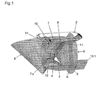
- Fig. 1 shows a spatial representation during the design phase of a stator.
- a cylinder 1, the limiting flow-guiding wall 1.1 of a stator 2 is concentrically cut from an imaginary, conical or funnel-shaped Element 3.
- the element 3 protrudes with its tip 4 into the cylinder 1.
- the here - for reasons of clarity - not shown axes of Element 3 and cylinder 1 coincide.
- the imaginary conical or funnel-shaped Element 3 has an opening angle of the order of magnitude of up to 130 ° can accept.
- the element 3 has a lateral surface 5, which is the basis for a scavenging arranged blade edge 6 of a blade 7 forms.
- An arrow 8 symbolizes the flow direction through the stator 2.
- Another imaginary cone element 9 is free standing in the room next to the cylinder 1 shown, wherein the lateral surface of the cone 9 intersects the cylinder 1. Not here shown axes of cone 9 and cylinder 1 are at a distance and at an angle to each other.
- the flow-guiding surface disposed within the cylinder 1 Guide vane 7 is part of the cylinder 1 cutting lateral surface of the cone 9.
- the cone 9 is located in the flow direction of the arrow 8 right in addition to the stator 2.
- the stator 2 has in this embodiment via fasteners 10 and 10.1, with which it is attached to a later installation location and at which a - not shown here - impeller is arranged with a drive.
- the section line of the cone 9 with the cylinder 1 forms the blade outer edge, with the a vane in the stator 2 is attached to the wall 1.1.
- This blade edge lies on a larger radius of the conical surface of the cone 9, as the free in the Space standing blade inner edge 12, on a smaller radius of the cone 9 is arranged.
- the cutting edge of the conical surface of the cone 9 with the lateral surface of the conical or funnel-shaped element 3, the blade inlet edge 6 forms a Guide vane 7.
- Lines a - b correspond to the cutting lines of the conical surface of the cone 9 with the cylinder 1 and the conical or funnel-shaped element 3 from the illustration of Fig.1.
- the line a corresponds to those blade outer edge 13, with the one vane 7 in the stator 2 attached to the flow-guiding wall 1.1 is.
- a line b forms at the intersection of the cone 9 with the element 3, the blade leading edge 6 of a vane 7 from.
- the line c corresponds to a circular arc on a plane and vertical section to Axis of the cone 9. Their position is determined by a dimension required in the design of the stator free ball passage through the hubless stator determined.
- the line c corresponds the blade inner edge 12 of a vane. 7
- a guide vane 7 determining lines a - e a vane can be cut from a sheet metal blank before or after a forming process become.
- a forming process is done with the help of tapered rollers or other forming techniques performed.
- Such a vane is welded in a cylindrical stator. This results in a well-defined position between the blade outer edge 13 and the flow-guiding wall 1.1 at the appropriate blunt attachment and thus a simple fast attachment, for example by means of welding technology, is possible.
- a stator shell 2 is designed diffuser-shaped, would analogous in Fig. 1 instead of a cylinder 1 a corresponding diffuser-shaped Truncated cone or similar component find application.
- the cutting lines of such diffuser-shaped cylinder replacement with the element 3 and the cone 9 would then the Determine the inside, outside and blade leading edge of the vanes.
- the generator of such a vane is any line in the space that the Condition meets that it lies on the cone surface to be formed.
- This line is particularly well recognizable in the area of the trailing edge when the exit angle the vane is at 90 ° or as the trailing edge when the exit angle exactly 90 °.
- the line d or the blade outlet edge 11 is always vertical on blade inner edge 12.
- the blade leading edge 6 as a free cut curve, which serves as a generatrix of the conical surface of the first cone 3 is no longer obvious, though, as it is compulsory on the conical surface of which lies, with rotation about the cone axis the same conical surface will generate.
- the element 3 is a cone educated. If a different course of the blade leading edge 6 is desired, then the element 3 also have a funnel-shaped course, in the mathematical Meaning no cone.
Landscapes
- Engineering & Computer Science (AREA)
- Mechanical Engineering (AREA)
- General Engineering & Computer Science (AREA)
- Structures Of Non-Positive Displacement Pumps (AREA)
- Rotary Pumps (AREA)
Abstract
Description
- Fig. 1
- eine räumliche Darstellung von begrenzenden Flächen beim Entwurf eines Leitrades und die
- Fig. 2
- eine Abwicklung eines Leitschaufel-Rohlings.
Claims (12)
- Kreiselpumpe axialer oder halbaxialer Bauart, mit einem auf der Druckseite eines Laufrades gelegenen Leitrad (2) , dessen im wesentlichen radial verlaufende Leitschaufeln (7, 7.x) mit einer Schaufelaußenkante (13) an einer strömungsführenden Wand (1.1) angeordnet sind, wobei die Eintrittskanten (6) der Leitschaufeln (7) in Strömungsrichtung (8) zur Laufraddrehachse hin fliehend angeordnet sind und zwischen den Schaufelinnenkanten (12) der Leitschaufeln (7) ein freier nabenloser Durchlass gebildet ist, dadurch gekennzeichnet, dass die Leitschaufeln (7) als Blechformteile gestaltet sind, wobei die Leitschaufel-Rohlinge als Abwicklung einer Kegelmantelfläche ausgebildet sind und die geformten Leitschaufeln (7, 7.x) Ausschnitte dieser Kegelmantelfläche sind.
- Kreiselpumpe nach Anspruch 1, dadurch gekennzeichnet, dass die Leitschaufeln (7, 7.x) als Abwicklung von mehreren, tangential aneinander angrenzender Kegelmantelflächen ausgebildet sind.
- Kreiselpumpe nach Anspruch 1 oder 2, dadurch gekennzeichnet, dass eine auf einem kleineren Radius des Kegels (9) angeordnete Schaufelseitenkante die zur Laufraddrehachse nächst gelegene, freie Schaufelinnenkante (12) der Leitschaufeln (7, 7.x) bildet.
- Kreiselpumpe nach Anspruch 1, 2 oder 3, dadurch gekennzeichnet, dass eine in Richtung zu einem größeren Radius des Kegels (9) angeordnete Schaufelseitenkante eine am Leitradgehäuse (2) befestigte Schaufelaußenkante (13) bildet, wobei die Schaufelaußenkante (13) gebildet ist aus einer Schnittkurve der Kegelmantelfläche mit der strömungsführenden Wand (1.1).
- Kreiselpumpe nach den Ansprüchen 1, 2, 3 oder 4, dadurch gekennzeichnet, dass eine Schaufeleintrittskante (6) als Schnittkurve einer Leitradschaufel (7, 7.x) mit einer um die Laufraddrehachse konzentrisch angeordneten, kegel- oder trichterförmigen Element (3) gebildet ist und dieses Element (3) einen Öffnungswinkel von bis zu 130° aufweist.
- Kreiselpumpe nach Anspruch 5, dadurch gekennzeichnet, dass ein Leitschaufel-Eintrittswinkel ∼ zu abnehmenden Leitradradius hin gleich bleibt oder kleiner wird.
- Kreiselpumpe nach den Ansprüchen 1 bis 6, dadurch gekennzeichnet, dass bei einem Leitradaustrittswinkel von 90° eine Schaufelaustrittskante (11) der Leitschaufeln (7, 7.x) einer Erzeugenden der Mantelfläche des Kegels (9) entspricht.
- Kreiselpumpe nach einem der Ansprüche 1 bis 7, dadurch gekennzeichnet, dass zwischen Schaufeleintrittskante (6) und freier Schaufelinnenkante (12) ein abgerundeter Übergang (3) angeordnet ist.
- Kreiselpumpe nach einem der Ansprüche 1 bis 8, dadurch gekennzeichnet, dass aus einem umgeformten Leitschaufel-Rohling mit größeren Flächeninhalt die Kontur einer zu montierenden Leitschaufel (7, 7.x) kleineren Flächeninhalts entnommen ist.
- Kreiselpumpe nach einem der Ansprüche 1 bis 9, dadurch gekennzeichnet, dass die strömungsführende Wand (1.1) des Leitradgehäuses (2) als ein kegel- oder rohrförmig ausgebildetes Blechformteil gestaltet ist.
- Kreiselpumpe nach einem der Ansprüche 1 bis 10, dadurch gekennzeichnet, dass ein Laufrad axialer oder halbaxialer Bauart vor oder innerhalb des Leitradgehäuses (2) angeordnet ist.
- Kreiselpumpe nach einem der Ansprüche 1 bis 11, dadurch gekennzeichnet, dass die Schaufelaustrittskante 11 senkrecht auf der Schaufelinnenkante 12 steht.
Applications Claiming Priority (2)
| Application Number | Priority Date | Filing Date | Title |
|---|---|---|---|
| DE10346058A DE10346058A1 (de) | 2003-10-04 | 2003-10-04 | Kreiselpumpen-Leitrad |
| DE10346058 | 2003-10-04 |
Publications (3)
| Publication Number | Publication Date |
|---|---|
| EP1520992A2 true EP1520992A2 (de) | 2005-04-06 |
| EP1520992A3 EP1520992A3 (de) | 2005-07-27 |
| EP1520992B1 EP1520992B1 (de) | 2006-06-21 |
Family
ID=34306248
Family Applications (1)
| Application Number | Title | Priority Date | Filing Date |
|---|---|---|---|
| EP04020975A Expired - Lifetime EP1520992B1 (de) | 2003-10-04 | 2004-09-03 | Kreiselpumpen-Leitrad |
Country Status (3)
| Country | Link |
|---|---|
| EP (1) | EP1520992B1 (de) |
| AT (1) | ATE331143T1 (de) |
| DE (2) | DE10346058A1 (de) |
Cited By (1)
| Publication number | Priority date | Publication date | Assignee | Title |
|---|---|---|---|---|
| CN105756956A (zh) * | 2016-04-05 | 2016-07-13 | 镇江江大泵业科技有限公司 | 一种新型切割式潜水排污泵 |
Family Cites Families (4)
| Publication number | Priority date | Publication date | Assignee | Title |
|---|---|---|---|---|
| CH237680A (de) * | 1942-07-21 | 1945-05-15 | Voith Gmbh J M | Aus Blech gebogene Leitschaufel für Axialgebläse. |
| SE384070B (sv) * | 1974-07-23 | 1976-04-12 | Stenberg Flygt Ab | Propellerpump |
| DE3872139D1 (de) * | 1987-09-30 | 1992-07-23 | Winkelmann & Pannhoff Gmbh | Verfahren zur herstellung von foerder und/oder leiteinrichtungen fuer stroemungsmaschinen und nach diesem verfahren hergestelltes radial-laufrad, insbesondere kuehlmittelpumpenrad fuer brennkraftmaschinen. |
| DE4330098A1 (de) * | 1993-09-06 | 1995-03-09 | Klein Schanzlin & Becker Ag | Als Blechformteil ausgebildete Leiteinrichtung |
-
2003
- 2003-10-04 DE DE10346058A patent/DE10346058A1/de not_active Withdrawn
-
2004
- 2004-09-03 AT AT04020975T patent/ATE331143T1/de active
- 2004-09-03 DE DE502004000817T patent/DE502004000817D1/de not_active Expired - Lifetime
- 2004-09-03 EP EP04020975A patent/EP1520992B1/de not_active Expired - Lifetime
Cited By (1)
| Publication number | Priority date | Publication date | Assignee | Title |
|---|---|---|---|---|
| CN105756956A (zh) * | 2016-04-05 | 2016-07-13 | 镇江江大泵业科技有限公司 | 一种新型切割式潜水排污泵 |
Also Published As
| Publication number | Publication date |
|---|---|
| EP1520992A3 (de) | 2005-07-27 |
| ATE331143T1 (de) | 2006-07-15 |
| EP1520992B1 (de) | 2006-06-21 |
| DE10346058A1 (de) | 2005-04-21 |
| DE502004000817D1 (de) | 2006-08-03 |
Similar Documents
| Publication | Publication Date | Title |
|---|---|---|
| DE69101953T2 (de) | Mehrphasige Pump- oder Kompressionsvorrichtung und ihre Anwendung. | |
| DE69203705T2 (de) | Stator zur Einführung von Luft in das Innere einer Turbomaschine und Verfahren zum Montieren einer Schaufel dieses Stators. | |
| EP1749564B1 (de) | Stabilisator zum Vermischen oder Stabilisieren eines Gemisches mittels eines hydrodynamischen Kavitationsfeldes | |
| EP1801422B1 (de) | Ventilator und Ventilatorflügel | |
| EP2927503B1 (de) | Gasturbinenverdichter, Flugtriebwerk und Auslegungsverfahren | |
| EP3702620B1 (de) | Axialventilator mit geräuschreduzierenden lüfterradschaufeln, die bohrungen aufweisen | |
| DE2551614A1 (de) | Axial kurzer axialventilator | |
| EP1632662B1 (de) | Strömungsarbeitsmaschine mit Fluidentnahme | |
| DE2827188A1 (de) | Bohrlochsieb | |
| DE202013101943U1 (de) | Vorrichtung zur Verringerung des Antriebsleistungsbedarfs eines Wasserfahrzeuges | |
| DE69625917T2 (de) | Radiales lüfterrad | |
| DE2653630C2 (de) | Vorrichtung zum Pumpen von Fluiden | |
| AT398813B (de) | Ventilatoreinheit | |
| WO1996013668A1 (de) | Radialverdichter oder radialturbine mit einem leitschaufeln aufweisenden diffusor oder turbinenleitkranz | |
| EP2133574A2 (de) | Räumliches Schutzgitter für Axiallüfter und Verfahren zur Herstellung des Schutzgitters | |
| WO2018138263A1 (de) | Hydrofoil für ein wasserfahrzeug | |
| DE102014219058A1 (de) | Radialverdichterlaufrad und zugehöriger Radialverdichter | |
| DE3142663A1 (de) | "spritzrohr mit flachstrahlduesen" | |
| EP1520992B1 (de) | Kreiselpumpen-Leitrad | |
| DE68915278T2 (de) | Leitschaufel für axialgebläse. | |
| DE3433647C2 (de) | Zerkleinerungsvorrichtung für Abwasseranlagen | |
| DE3107607A1 (de) | Filter mit feststehendem siebeinsatz insbesondere fuer industriewasser | |
| EP2146059B1 (de) | Verwendung eines Siebes, sowie Dampfturbinenanlage | |
| EP2811170A1 (de) | Radiallüfter | |
| DE2112088C2 (de) | Wirbelerzeugende Vorrichtung zum Einbau in ein Wirbelrohr eines Zentrifugalabscheiders |
Legal Events
| Date | Code | Title | Description |
|---|---|---|---|
| PUAI | Public reference made under article 153(3) epc to a published international application that has entered the european phase |
Free format text: ORIGINAL CODE: 0009012 |
|
| AK | Designated contracting states |
Kind code of ref document: A2 Designated state(s): AT BE BG CH CY CZ DE DK EE ES FI FR GB GR HU IE IT LI LU MC NL PL PT RO SE SI SK TR |
|
| AX | Request for extension of the european patent |
Extension state: AL HR LT LV MK |
|
| PUAL | Search report despatched |
Free format text: ORIGINAL CODE: 0009013 |
|
| AK | Designated contracting states |
Kind code of ref document: A3 Designated state(s): AT BE BG CH CY CZ DE DK EE ES FI FR GB GR HU IE IT LI LU MC NL PL PT RO SE SI SK TR |
|
| AX | Request for extension of the european patent |
Extension state: AL HR LT LV MK |
|
| RIC1 | Information provided on ipc code assigned before grant |
Ipc: 7F 04D 29/54 B Ipc: 7F 04D 29/44 A |
|
| 17P | Request for examination filed |
Effective date: 20050618 |
|
| GRAP | Despatch of communication of intention to grant a patent |
Free format text: ORIGINAL CODE: EPIDOSNIGR1 |
|
| AKX | Designation fees paid |
Designated state(s): AT BE BG CH CY CZ DE DK EE ES FI FR GB GR HU IE IT LI LU MC NL PL PT RO SE SI SK TR |
|
| GRAS | Grant fee paid |
Free format text: ORIGINAL CODE: EPIDOSNIGR3 |
|
| GRAA | (expected) grant |
Free format text: ORIGINAL CODE: 0009210 |
|
| AK | Designated contracting states |
Kind code of ref document: B1 Designated state(s): AT BE BG CH CY CZ DE DK EE ES FI FR GB GR HU IE IT LI LU MC NL PL PT RO SE SI SK TR |
|
| PG25 | Lapsed in a contracting state [announced via postgrant information from national office to epo] |
Ref country code: SI Free format text: LAPSE BECAUSE OF FAILURE TO SUBMIT A TRANSLATION OF THE DESCRIPTION OR TO PAY THE FEE WITHIN THE PRESCRIBED TIME-LIMIT Effective date: 20060621 Ref country code: RO Free format text: LAPSE BECAUSE OF FAILURE TO SUBMIT A TRANSLATION OF THE DESCRIPTION OR TO PAY THE FEE WITHIN THE PRESCRIBED TIME-LIMIT Effective date: 20060621 Ref country code: PL Free format text: LAPSE BECAUSE OF FAILURE TO SUBMIT A TRANSLATION OF THE DESCRIPTION OR TO PAY THE FEE WITHIN THE PRESCRIBED TIME-LIMIT Effective date: 20060621 Ref country code: CZ Free format text: LAPSE BECAUSE OF FAILURE TO SUBMIT A TRANSLATION OF THE DESCRIPTION OR TO PAY THE FEE WITHIN THE PRESCRIBED TIME-LIMIT Effective date: 20060621 Ref country code: SK Free format text: LAPSE BECAUSE OF FAILURE TO SUBMIT A TRANSLATION OF THE DESCRIPTION OR TO PAY THE FEE WITHIN THE PRESCRIBED TIME-LIMIT Effective date: 20060621 Ref country code: NL Free format text: LAPSE BECAUSE OF FAILURE TO SUBMIT A TRANSLATION OF THE DESCRIPTION OR TO PAY THE FEE WITHIN THE PRESCRIBED TIME-LIMIT Effective date: 20060621 Ref country code: IE Free format text: LAPSE BECAUSE OF FAILURE TO SUBMIT A TRANSLATION OF THE DESCRIPTION OR TO PAY THE FEE WITHIN THE PRESCRIBED TIME-LIMIT Effective date: 20060621 Ref country code: FI Free format text: LAPSE BECAUSE OF FAILURE TO SUBMIT A TRANSLATION OF THE DESCRIPTION OR TO PAY THE FEE WITHIN THE PRESCRIBED TIME-LIMIT Effective date: 20060621 |
|
| REG | Reference to a national code |
Ref country code: GB Ref legal event code: FG4D Free format text: NOT ENGLISH |
|
| REG | Reference to a national code |
Ref country code: CH Ref legal event code: EP |
|
| REG | Reference to a national code |
Ref country code: IE Ref legal event code: FG4D Free format text: LANGUAGE OF EP DOCUMENT: GERMAN |
|
| REF | Corresponds to: |
Ref document number: 502004000817 Country of ref document: DE Date of ref document: 20060803 Kind code of ref document: P |
|
| PG25 | Lapsed in a contracting state [announced via postgrant information from national office to epo] |
Ref country code: SE Free format text: LAPSE BECAUSE OF FAILURE TO SUBMIT A TRANSLATION OF THE DESCRIPTION OR TO PAY THE FEE WITHIN THE PRESCRIBED TIME-LIMIT Effective date: 20060921 Ref country code: DK Free format text: LAPSE BECAUSE OF FAILURE TO SUBMIT A TRANSLATION OF THE DESCRIPTION OR TO PAY THE FEE WITHIN THE PRESCRIBED TIME-LIMIT Effective date: 20060921 |
|
| PG25 | Lapsed in a contracting state [announced via postgrant information from national office to epo] |
Ref country code: MC Free format text: LAPSE BECAUSE OF NON-PAYMENT OF DUE FEES Effective date: 20060930 |
|
| PG25 | Lapsed in a contracting state [announced via postgrant information from national office to epo] |
Ref country code: ES Free format text: LAPSE BECAUSE OF FAILURE TO SUBMIT A TRANSLATION OF THE DESCRIPTION OR TO PAY THE FEE WITHIN THE PRESCRIBED TIME-LIMIT Effective date: 20061002 |
|
| GBT | Gb: translation of ep patent filed (gb section 77(6)(a)/1977) |
Effective date: 20060924 |
|
| PG25 | Lapsed in a contracting state [announced via postgrant information from national office to epo] |
Ref country code: PT Free format text: LAPSE BECAUSE OF FAILURE TO SUBMIT A TRANSLATION OF THE DESCRIPTION OR TO PAY THE FEE WITHIN THE PRESCRIBED TIME-LIMIT Effective date: 20061121 |
|
| NLV1 | Nl: lapsed or annulled due to failure to fulfill the requirements of art. 29p and 29m of the patents act | ||
| ET | Fr: translation filed | ||
| REG | Reference to a national code |
Ref country code: IE Ref legal event code: FD4D |
|
| PLBE | No opposition filed within time limit |
Free format text: ORIGINAL CODE: 0009261 |
|
| STAA | Information on the status of an ep patent application or granted ep patent |
Free format text: STATUS: NO OPPOSITION FILED WITHIN TIME LIMIT |
|
| 26N | No opposition filed |
Effective date: 20070322 |
|
| PG25 | Lapsed in a contracting state [announced via postgrant information from national office to epo] |
Ref country code: GR Free format text: LAPSE BECAUSE OF FAILURE TO SUBMIT A TRANSLATION OF THE DESCRIPTION OR TO PAY THE FEE WITHIN THE PRESCRIBED TIME-LIMIT Effective date: 20060922 |
|
| PG25 | Lapsed in a contracting state [announced via postgrant information from national office to epo] |
Ref country code: EE Free format text: LAPSE BECAUSE OF FAILURE TO SUBMIT A TRANSLATION OF THE DESCRIPTION OR TO PAY THE FEE WITHIN THE PRESCRIBED TIME-LIMIT Effective date: 20060621 Ref country code: BG Free format text: LAPSE BECAUSE OF FAILURE TO SUBMIT A TRANSLATION OF THE DESCRIPTION OR TO PAY THE FEE WITHIN THE PRESCRIBED TIME-LIMIT Effective date: 20060921 |
|
| PG25 | Lapsed in a contracting state [announced via postgrant information from national office to epo] |
Ref country code: LU Free format text: LAPSE BECAUSE OF NON-PAYMENT OF DUE FEES Effective date: 20060903 Ref country code: HU Free format text: LAPSE BECAUSE OF FAILURE TO SUBMIT A TRANSLATION OF THE DESCRIPTION OR TO PAY THE FEE WITHIN THE PRESCRIBED TIME-LIMIT Effective date: 20061222 Ref country code: TR Free format text: LAPSE BECAUSE OF FAILURE TO SUBMIT A TRANSLATION OF THE DESCRIPTION OR TO PAY THE FEE WITHIN THE PRESCRIBED TIME-LIMIT Effective date: 20060621 |
|
| PG25 | Lapsed in a contracting state [announced via postgrant information from national office to epo] |
Ref country code: CY Free format text: LAPSE BECAUSE OF FAILURE TO SUBMIT A TRANSLATION OF THE DESCRIPTION OR TO PAY THE FEE WITHIN THE PRESCRIBED TIME-LIMIT Effective date: 20060621 |
|
| REG | Reference to a national code |
Ref country code: CH Ref legal event code: PL |
|
| PG25 | Lapsed in a contracting state [announced via postgrant information from national office to epo] |
Ref country code: LI Free format text: LAPSE BECAUSE OF NON-PAYMENT OF DUE FEES Effective date: 20060930 Ref country code: CH Free format text: LAPSE BECAUSE OF NON-PAYMENT OF DUE FEES Effective date: 20060930 |
|
| PG25 | Lapsed in a contracting state [announced via postgrant information from national office to epo] |
Ref country code: CH Free format text: LAPSE BECAUSE OF NON-PAYMENT OF DUE FEES Effective date: 20080930 Ref country code: LI Free format text: LAPSE BECAUSE OF NON-PAYMENT OF DUE FEES Effective date: 20080930 |
|
| PGFP | Annual fee paid to national office [announced via postgrant information from national office to epo] |
Ref country code: GB Payment date: 20120925 Year of fee payment: 9 |
|
| PGFP | Annual fee paid to national office [announced via postgrant information from national office to epo] |
Ref country code: DE Payment date: 20120912 Year of fee payment: 9 Ref country code: IT Payment date: 20120922 Year of fee payment: 9 |
|
| PGFP | Annual fee paid to national office [announced via postgrant information from national office to epo] |
Ref country code: FR Payment date: 20121011 Year of fee payment: 9 Ref country code: BE Payment date: 20121001 Year of fee payment: 9 |
|
| PGFP | Annual fee paid to national office [announced via postgrant information from national office to epo] |
Ref country code: AT Payment date: 20120924 Year of fee payment: 9 |
|
| BERE | Be: lapsed |
Owner name: *KSB A.G. Effective date: 20130930 |
|
| REG | Reference to a national code |
Ref country code: AT Ref legal event code: MM01 Ref document number: 331143 Country of ref document: AT Kind code of ref document: T Effective date: 20130903 |
|
| GBPC | Gb: european patent ceased through non-payment of renewal fee |
Effective date: 20130903 |
|
| REG | Reference to a national code |
Ref country code: DE Ref legal event code: R119 Ref document number: 502004000817 Country of ref document: DE Effective date: 20140401 |
|
| REG | Reference to a national code |
Ref country code: FR Ref legal event code: ST Effective date: 20140530 |
|
| PG25 | Lapsed in a contracting state [announced via postgrant information from national office to epo] |
Ref country code: BE Free format text: LAPSE BECAUSE OF NON-PAYMENT OF DUE FEES Effective date: 20130930 Ref country code: GB Free format text: LAPSE BECAUSE OF NON-PAYMENT OF DUE FEES Effective date: 20130903 |
|
| PG25 | Lapsed in a contracting state [announced via postgrant information from national office to epo] |
Ref country code: FR Free format text: LAPSE BECAUSE OF NON-PAYMENT OF DUE FEES Effective date: 20130930 Ref country code: DE Free format text: LAPSE BECAUSE OF NON-PAYMENT OF DUE FEES Effective date: 20140401 Ref country code: AT Free format text: LAPSE BECAUSE OF NON-PAYMENT OF DUE FEES Effective date: 20130903 Ref country code: IT Free format text: LAPSE BECAUSE OF NON-PAYMENT OF DUE FEES Effective date: 20130903 |