EP1520698B1 - Method of controlling printing on both surfaces of a sheet of print media - Google Patents
Method of controlling printing on both surfaces of a sheet of print media Download PDFInfo
- Publication number
- EP1520698B1 EP1520698B1 EP04105962A EP04105962A EP1520698B1 EP 1520698 B1 EP1520698 B1 EP 1520698B1 EP 04105962 A EP04105962 A EP 04105962A EP 04105962 A EP04105962 A EP 04105962A EP 1520698 B1 EP1520698 B1 EP 1520698B1
- Authority
- EP
- European Patent Office
- Prior art keywords
- page
- printhead
- printer
- bit
- Prior art date
- Legal status (The legal status is an assumption and is not a legal conclusion. Google has not performed a legal analysis and makes no representation as to the accuracy of the status listed.)
- Expired - Lifetime
Links
- 238000007639 printing Methods 0.000 title claims abstract description 146
- 238000000034 method Methods 0.000 title claims description 54
- 239000000872 buffer Substances 0.000 claims description 102
- 230000015654 memory Effects 0.000 claims description 37
- 238000004891 communication Methods 0.000 claims description 14
- 238000012546 transfer Methods 0.000 abstract description 136
- 238000007789 sealing Methods 0.000 abstract description 11
- 238000006073 displacement reaction Methods 0.000 abstract description 7
- 238000001704 evaporation Methods 0.000 abstract description 3
- 230000008020 evaporation Effects 0.000 abstract description 3
- 239000010410 layer Substances 0.000 description 124
- 239000000976 ink Substances 0.000 description 105
- 230000006835 compression Effects 0.000 description 54
- 238000007906 compression Methods 0.000 description 54
- 238000010304 firing Methods 0.000 description 45
- 239000003086 colorant Substances 0.000 description 40
- 230000000875 corresponding effect Effects 0.000 description 29
- 230000008569 process Effects 0.000 description 29
- 230000006870 function Effects 0.000 description 26
- 238000004140 cleaning Methods 0.000 description 25
- 238000009877 rendering Methods 0.000 description 23
- 238000010586 diagram Methods 0.000 description 21
- 238000011068 loading method Methods 0.000 description 21
- 230000007246 mechanism Effects 0.000 description 15
- 229920002451 polyvinyl alcohol Polymers 0.000 description 14
- 230000001276 controlling effect Effects 0.000 description 12
- 238000013461 design Methods 0.000 description 12
- 230000005540 biological transmission Effects 0.000 description 11
- 239000002131 composite material Substances 0.000 description 11
- 230000001360 synchronised effect Effects 0.000 description 10
- 238000004364 calculation method Methods 0.000 description 9
- 239000000463 material Substances 0.000 description 9
- 230000004044 response Effects 0.000 description 8
- 238000012360 testing method Methods 0.000 description 8
- 230000009471 action Effects 0.000 description 7
- 230000006837 decompression Effects 0.000 description 7
- 239000000203 mixture Substances 0.000 description 7
- 238000000465 moulding Methods 0.000 description 7
- 238000009826 distribution Methods 0.000 description 6
- 230000000694 effects Effects 0.000 description 6
- 238000007726 management method Methods 0.000 description 6
- 229910052751 metal Inorganic materials 0.000 description 6
- 239000002184 metal Substances 0.000 description 6
- GXVMAQACUOSFJF-UHFFFAOYSA-N 1,3-dichloro-5-(2-chlorophenyl)benzene Chemical compound ClC1=CC(Cl)=CC(C=2C(=CC=CC=2)Cl)=C1 GXVMAQACUOSFJF-UHFFFAOYSA-N 0.000 description 5
- NRTOMJZYCJJWKI-UHFFFAOYSA-N Titanium nitride Chemical compound [Ti]#N NRTOMJZYCJJWKI-UHFFFAOYSA-N 0.000 description 5
- 230000009977 dual effect Effects 0.000 description 5
- 238000000926 separation method Methods 0.000 description 5
- 230000001419 dependent effect Effects 0.000 description 4
- 230000003993 interaction Effects 0.000 description 4
- 239000007787 solid Substances 0.000 description 4
- RIBGNAJQTOXRDK-UHFFFAOYSA-N 1,3-dichloro-5-(3-chlorophenyl)benzene Chemical compound ClC1=CC=CC(C=2C=C(Cl)C=C(Cl)C=2)=C1 RIBGNAJQTOXRDK-UHFFFAOYSA-N 0.000 description 3
- 230000002745 absorbent Effects 0.000 description 3
- 239000002250 absorbent Substances 0.000 description 3
- 238000013459 approach Methods 0.000 description 3
- 230000000712 assembly Effects 0.000 description 3
- 238000000429 assembly Methods 0.000 description 3
- 230000015572 biosynthetic process Effects 0.000 description 3
- 230000003139 buffering effect Effects 0.000 description 3
- 230000015556 catabolic process Effects 0.000 description 3
- 230000008859 change Effects 0.000 description 3
- 238000006731 degradation reaction Methods 0.000 description 3
- 238000005516 engineering process Methods 0.000 description 3
- 238000003384 imaging method Methods 0.000 description 3
- 238000004519 manufacturing process Methods 0.000 description 3
- 239000011159 matrix material Substances 0.000 description 3
- 230000010076 replication Effects 0.000 description 3
- 238000006748 scratching Methods 0.000 description 3
- 230000002393 scratching effect Effects 0.000 description 3
- 238000003860 storage Methods 0.000 description 3
- 230000002459 sustained effect Effects 0.000 description 3
- 230000036413 temperature sense Effects 0.000 description 3
- 230000000007 visual effect Effects 0.000 description 3
- 238000007792 addition Methods 0.000 description 2
- 238000006243 chemical reaction Methods 0.000 description 2
- 239000002537 cosmetic Substances 0.000 description 2
- 238000009792 diffusion process Methods 0.000 description 2
- 230000007613 environmental effect Effects 0.000 description 2
- 210000003195 fascia Anatomy 0.000 description 2
- 238000011049 filling Methods 0.000 description 2
- 238000009499 grossing Methods 0.000 description 2
- 238000002955 isolation Methods 0.000 description 2
- 230000001404 mediated effect Effects 0.000 description 2
- 230000004048 modification Effects 0.000 description 2
- 238000012986 modification Methods 0.000 description 2
- 230000003287 optical effect Effects 0.000 description 2
- 238000013139 quantization Methods 0.000 description 2
- 230000009467 reduction Effects 0.000 description 2
- 230000035945 sensitivity Effects 0.000 description 2
- 239000000243 solution Substances 0.000 description 2
- FEACDYATMHKJPE-JXHOJRNMSA-N xxxx-3 Chemical compound C1CC(C)CC(OC)C(O)C(C)\C=C(C)\C(OC(N)=O)C(OC)CC\C=C(C)\C(=O)NC2=CC(O)=C(O)C1=C2 FEACDYATMHKJPE-JXHOJRNMSA-N 0.000 description 2
- 238000012935 Averaging Methods 0.000 description 1
- 235000006679 Mentha X verticillata Nutrition 0.000 description 1
- 235000002899 Mentha suaveolens Nutrition 0.000 description 1
- 235000001636 Mentha x rotundifolia Nutrition 0.000 description 1
- 101100063942 Neurospora crassa (strain ATCC 24698 / 74-OR23-1A / CBS 708.71 / DSM 1257 / FGSC 987) dot-1 gene Proteins 0.000 description 1
- 241000316887 Saissetia oleae Species 0.000 description 1
- XUIMIQQOPSSXEZ-UHFFFAOYSA-N Silicon Chemical compound [Si] XUIMIQQOPSSXEZ-UHFFFAOYSA-N 0.000 description 1
- 229910000639 Spring steel Inorganic materials 0.000 description 1
- 230000002411 adverse Effects 0.000 description 1
- 230000008901 benefit Effects 0.000 description 1
- 238000010276 construction Methods 0.000 description 1
- 238000012937 correction Methods 0.000 description 1
- 230000002596 correlated effect Effects 0.000 description 1
- 230000001351 cycling effect Effects 0.000 description 1
- 230000007423 decrease Effects 0.000 description 1
- 230000003247 decreasing effect Effects 0.000 description 1
- 230000001627 detrimental effect Effects 0.000 description 1
- 238000001035 drying Methods 0.000 description 1
- 238000005530 etching Methods 0.000 description 1
- 239000006260 foam Substances 0.000 description 1
- 230000000977 initiatory effect Effects 0.000 description 1
- 238000001746 injection moulding Methods 0.000 description 1
- 239000003550 marker Substances 0.000 description 1
- 238000005259 measurement Methods 0.000 description 1
- 238000002156 mixing Methods 0.000 description 1
- 238000012544 monitoring process Methods 0.000 description 1
- 230000008520 organization Effects 0.000 description 1
- 239000003973 paint Substances 0.000 description 1
- 238000010587 phase diagram Methods 0.000 description 1
- 229920003023 plastic Polymers 0.000 description 1
- 239000004033 plastic Substances 0.000 description 1
- 239000002243 precursor Substances 0.000 description 1
- 238000011084 recovery Methods 0.000 description 1
- 239000004065 semiconductor Substances 0.000 description 1
- 229910052710 silicon Inorganic materials 0.000 description 1
- 239000010703 silicon Substances 0.000 description 1
- 239000002356 single layer Substances 0.000 description 1
- 230000009466 transformation Effects 0.000 description 1
- 238000011144 upstream manufacturing Methods 0.000 description 1
- 230000003936 working memory Effects 0.000 description 1
Images


Classifications
-
- B—PERFORMING OPERATIONS; TRANSPORTING
- B41—PRINTING; LINING MACHINES; TYPEWRITERS; STAMPS
- B41J—TYPEWRITERS; SELECTIVE PRINTING MECHANISMS, i.e. MECHANISMS PRINTING OTHERWISE THAN FROM A FORME; CORRECTION OF TYPOGRAPHICAL ERRORS
- B41J3/00—Typewriters or selective printing or marking mechanisms characterised by the purpose for which they are constructed
- B41J3/44—Typewriters or selective printing mechanisms having dual functions or combined with, or coupled to, apparatus performing other functions
- B41J3/445—Printers integrated in other types of apparatus, e.g. printers integrated in cameras
-
- B—PERFORMING OPERATIONS; TRANSPORTING
- B41—PRINTING; LINING MACHINES; TYPEWRITERS; STAMPS
- B41J—TYPEWRITERS; SELECTIVE PRINTING MECHANISMS, i.e. MECHANISMS PRINTING OTHERWISE THAN FROM A FORME; CORRECTION OF TYPOGRAPHICAL ERRORS
- B41J11/00—Devices or arrangements of selective printing mechanisms, e.g. ink-jet printers or thermal printers, for supporting or handling copy material in sheet or web form
- B41J11/0095—Detecting means for copy material, e.g. for detecting or sensing presence of copy material or its leading or trailing end
-
- B—PERFORMING OPERATIONS; TRANSPORTING
- B41—PRINTING; LINING MACHINES; TYPEWRITERS; STAMPS
- B41J—TYPEWRITERS; SELECTIVE PRINTING MECHANISMS, i.e. MECHANISMS PRINTING OTHERWISE THAN FROM A FORME; CORRECTION OF TYPOGRAPHICAL ERRORS
- B41J11/00—Devices or arrangements of selective printing mechanisms, e.g. ink-jet printers or thermal printers, for supporting or handling copy material in sheet or web form
- B41J11/36—Blanking or long feeds; Feeding to a particular line, e.g. by rotation of platen or feed roller
- B41J11/42—Controlling printing material conveyance for accurate alignment of the printing material with the printhead; Print registering
-
- B—PERFORMING OPERATIONS; TRANSPORTING
- B41—PRINTING; LINING MACHINES; TYPEWRITERS; STAMPS
- B41J—TYPEWRITERS; SELECTIVE PRINTING MECHANISMS, i.e. MECHANISMS PRINTING OTHERWISE THAN FROM A FORME; CORRECTION OF TYPOGRAPHICAL ERRORS
- B41J13/00—Devices or arrangements of selective printing mechanisms, e.g. ink-jet printers or thermal printers, specially adapted for supporting or handling copy material in short lengths, e.g. sheets
- B41J13/02—Rollers
- B41J13/03—Rollers driven, e.g. feed rollers separate from platen
-
- B—PERFORMING OPERATIONS; TRANSPORTING
- B41—PRINTING; LINING MACHINES; TYPEWRITERS; STAMPS
- B41J—TYPEWRITERS; SELECTIVE PRINTING MECHANISMS, i.e. MECHANISMS PRINTING OTHERWISE THAN FROM A FORME; CORRECTION OF TYPOGRAPHICAL ERRORS
- B41J13/00—Devices or arrangements of selective printing mechanisms, e.g. ink-jet printers or thermal printers, specially adapted for supporting or handling copy material in short lengths, e.g. sheets
- B41J13/02—Rollers
- B41J13/076—Construction of rollers; Bearings therefor
-
- B—PERFORMING OPERATIONS; TRANSPORTING
- B41—PRINTING; LINING MACHINES; TYPEWRITERS; STAMPS
- B41J—TYPEWRITERS; SELECTIVE PRINTING MECHANISMS, i.e. MECHANISMS PRINTING OTHERWISE THAN FROM A FORME; CORRECTION OF TYPOGRAPHICAL ERRORS
- B41J13/00—Devices or arrangements of selective printing mechanisms, e.g. ink-jet printers or thermal printers, specially adapted for supporting or handling copy material in short lengths, e.g. sheets
- B41J13/10—Sheet holders, retainers, movable guides, or stationary guides
- B41J13/103—Sheet holders, retainers, movable guides, or stationary guides for the sheet feeding section
-
- B—PERFORMING OPERATIONS; TRANSPORTING
- B41—PRINTING; LINING MACHINES; TYPEWRITERS; STAMPS
- B41J—TYPEWRITERS; SELECTIVE PRINTING MECHANISMS, i.e. MECHANISMS PRINTING OTHERWISE THAN FROM A FORME; CORRECTION OF TYPOGRAPHICAL ERRORS
- B41J2/00—Typewriters or selective printing mechanisms characterised by the printing or marking process for which they are designed
- B41J2/005—Typewriters or selective printing mechanisms characterised by the printing or marking process for which they are designed characterised by bringing liquid or particles selectively into contact with a printing material
- B41J2/01—Ink jet
- B41J2/135—Nozzles
- B41J2/145—Arrangement thereof
- B41J2/155—Arrangement thereof for line printing
-
- B—PERFORMING OPERATIONS; TRANSPORTING
- B41—PRINTING; LINING MACHINES; TYPEWRITERS; STAMPS
- B41J—TYPEWRITERS; SELECTIVE PRINTING MECHANISMS, i.e. MECHANISMS PRINTING OTHERWISE THAN FROM A FORME; CORRECTION OF TYPOGRAPHICAL ERRORS
- B41J2/00—Typewriters or selective printing mechanisms characterised by the printing or marking process for which they are designed
- B41J2/005—Typewriters or selective printing mechanisms characterised by the printing or marking process for which they are designed characterised by bringing liquid or particles selectively into contact with a printing material
- B41J2/01—Ink jet
- B41J2/135—Nozzles
- B41J2/165—Prevention or detection of nozzle clogging, e.g. cleaning, capping or moistening for nozzles
- B41J2/16505—Caps, spittoons or covers for cleaning or preventing drying out
- B41J2/16508—Caps, spittoons or covers for cleaning or preventing drying out connected with the printer frame
-
- B—PERFORMING OPERATIONS; TRANSPORTING
- B41—PRINTING; LINING MACHINES; TYPEWRITERS; STAMPS
- B41J—TYPEWRITERS; SELECTIVE PRINTING MECHANISMS, i.e. MECHANISMS PRINTING OTHERWISE THAN FROM A FORME; CORRECTION OF TYPOGRAPHICAL ERRORS
- B41J29/00—Details of, or accessories for, typewriters or selective printing mechanisms not otherwise provided for
- B41J29/02—Framework
- B41J29/023—Framework with reduced dimensions
-
- B—PERFORMING OPERATIONS; TRANSPORTING
- B41—PRINTING; LINING MACHINES; TYPEWRITERS; STAMPS
- B41J—TYPEWRITERS; SELECTIVE PRINTING MECHANISMS, i.e. MECHANISMS PRINTING OTHERWISE THAN FROM A FORME; CORRECTION OF TYPOGRAPHICAL ERRORS
- B41J29/00—Details of, or accessories for, typewriters or selective printing mechanisms not otherwise provided for
- B41J29/17—Cleaning arrangements
-
- B—PERFORMING OPERATIONS; TRANSPORTING
- B41—PRINTING; LINING MACHINES; TYPEWRITERS; STAMPS
- B41J—TYPEWRITERS; SELECTIVE PRINTING MECHANISMS, i.e. MECHANISMS PRINTING OTHERWISE THAN FROM A FORME; CORRECTION OF TYPOGRAPHICAL ERRORS
- B41J29/00—Details of, or accessories for, typewriters or selective printing mechanisms not otherwise provided for
- B41J29/38—Drives, motors, controls or automatic cut-off devices for the entire printing mechanism
-
- B—PERFORMING OPERATIONS; TRANSPORTING
- B41—PRINTING; LINING MACHINES; TYPEWRITERS; STAMPS
- B41J—TYPEWRITERS; SELECTIVE PRINTING MECHANISMS, i.e. MECHANISMS PRINTING OTHERWISE THAN FROM A FORME; CORRECTION OF TYPOGRAPHICAL ERRORS
- B41J3/00—Typewriters or selective printing or marking mechanisms characterised by the purpose for which they are constructed
- B41J3/60—Typewriters or selective printing or marking mechanisms characterised by the purpose for which they are constructed for printing on both faces of the printing material
-
- G—PHYSICS
- G06—COMPUTING; CALCULATING OR COUNTING
- G06K—GRAPHICAL DATA READING; PRESENTATION OF DATA; RECORD CARRIERS; HANDLING RECORD CARRIERS
- G06K15/00—Arrangements for producing a permanent visual presentation of the output data, e.g. computer output printers
- G06K15/02—Arrangements for producing a permanent visual presentation of the output data, e.g. computer output printers using printers
- G06K15/16—Means for paper feeding or form feeding
Definitions
- the present invention relates to a printer. More particularly, the invention relates to a high speed printer.
- the printer system is intended for use with various types of original equipment to be incorporated therein, either as a rack-mountable module or as an integral part of such a system.
- Japanese patent publication number 05-261979 discloses an inkjet printer that uses a pair of opposed synchronized transfer rollers. Ink droplets are discharged from a first inkjet printhead onto a first transfer roller and ink droplets are discharged from a second inkjet printhead onto a second transfer roller. Print media is passed between the rollers and the rollers thus transfer a printed image onto the print media. Applicant has found that a particular problem is the difficulty in achieving print synchronization. The Applicant has thus conceived the present invention to address this problem.
- the method may include synchronising printhead interfaces of both print controllers by means of a shared line synchronisation signal generated by the first print controller which is a master print controller.
- the method may include transmitting data relating to the pages to be printed from a host system to the master print controller by means of a host communications link, the master print controller determining whether or not said data are to be routed to the second print controller which is a slave print controller.
- the method may include receiving said data in its entirety in a memory of the master print controller before forwarding it to the slave print controller.
- the method may include selecting the master print controller to print the rear surface of the print media to ensure that the master print controller always has a page buffer available for a page description destined for the slave print controller.
- the method may include, periodically, transmitting predetermined data from the slave print controller to the master print controller.
- printer system which includes:
- page width printhead is to be understood as a printhead having a printing zone that prints one line at a time on a page, the line being parallel either to a longer edge or a shorter edge of the page.
- the line is printed as a whole as the page moves past the printhead and the printhead is stationary, i.e. it does not raster.
- a print media slot may be defined between the front panel and the carrier through which print media are ejected after printing of images on the print media.
- the carrier may include a chassis which is supported on a guide means in the housing.
- the receptacle for the supply of print media may then be a platen carried on the chassis.
- the receptacle for the supply of ink may be a receiving formation in which an ink cartridge is removably received.
- the receiving formation may include a locking arrangement for releasably locking the ink cartridge in position relative to the carrier and the print engine.
- a second print engine may be arranged in the housing, in opposed relationship to the print engine arranged on the carrier when the carrier is in its retracted position, for effecting printing on both surfaces of the print media.
- An indicating means may be contained in the front panel for indicating when printer consumables, being the supply of print media and the supply of ink, require replenishment.
- the indicating means may be in the form of a visual annunciator, such as one or more light emitting diodes.
- the specification also describes a print engine for a printer, the print engine including:
- the ink-ejecting means of the printhead may be a microelectromechanical device having a plurality of inkjet nozzles.
- the sealing means may be an elastomeric seal surrounding the ink-ejecting means.
- the sealing means may comprise a plurality of nested ribs surrounding a semi-conductor device defining the inkjet nozzles.
- the transfer means may include a transfer roller rotatably mounted adjacent to the printhead so that ink ejected by the printhead is deposited on a surface of the transfer roller.
- a transfer roller rotatably mounted adjacent to the printhead so that ink ejected by the printhead is deposited on a surface of the transfer roller.
- at least a surface of the transfer roller is of a wear resistant material which is resistant to pitting, scoring or scratching.
- at least the surface of the transfer roller may be of titanium nitride.
- the displacement means may include an electromagnetically operable device.
- the electromagnetically operable device may be a solenoid which, to draw the printhead away from the transfer means, requires a first, higher current and to hold the printhead in spaced relationship relative to the transfer means requires a second, lower current.
- the print engine may include an urging means for urging a sheet of print media into contact with the surface of the transfer means.
- the urging means may either be a pinch roller or, where two print engines are provided for effecting double-sided printing, a transfer roller of an opposed, aligned print engine.
- the print engine may also include a cleaning station for cleaning the surface of the transfer means, the cleaning station being arranged intermediate the urging means and the printhead.
- the cleaning station may include a cleaning element of an absorbent, resiliently flexible material, such as a sponge, and a wiper of a resiliently flexible material, the wiper being arranged intermediate the cleaning element and the printhead.
- the wiper may be in the form of a strip of rubber.
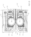
- the specification also describes a digital printing system for printing on both surfaces of a sheet of print media, the printing system including:
- the second print engine may be pivotally mounted with respect to the first print engine, the second print engine including a biasing means, in the form of a spring, for biasing its transfer roller into abutment with the transfer roller of the first print engine.
- a biasing means in the form of a spring
- One of the transfer rollers of both transfer rollers may act as an urging means for urging the sheet of print media past the transfer rollers.
- At least a surface of the transfer roller of each print engine may be of a wear resistant material which is resistant to pitting, scratching or scoring.
- the material may be titanium nitride.
- Each print engine may include a page width printhead with the transfer roller being of a similar length to the printhead.
- the printhead of each print engine may include an ink-ejecting means and a sealing means surrounding the ink-ejecting means.
- the ink-ejecting means of the printhead may be a microelectromechanical device having a plurality of inkjet nozzles.
- the sealing means may be an elastomeric seal surrounding the ink-ejecting means.
- each print engine When the printhead of each print engine is inoperative, it may bear against its associated transfer roller such that the sealing means seals the ink-ejecting means to inhibit evaporation of ink from the ink-ejecting means, each print engine including a displacement means for withdrawing the printhead from the transfer roller when printing is to be effected.
- the displacement means may include an electromagnetically operable device.
- the electromagnetically operable device may be a solenoid which, to draw the printhead away from the transfer roller to enable printing to be effected, requires a first, higher current, and to hold the printhead in spaced relationship relative to the transfer means requires a second, lower current.
- Each print engine may include a cleaning station, arranged upstream of the printhead, for cleaning the surface of the transfer roller.
- the cleaning station may include a cleaning element of an absorbent, resiliently flexible material such as a sponge, and a wiper of a resiliently flexible material arranged downstream of the cleaning element.
- the wiper may be of rubber.
- Each print engine may provide for process color output.
- the print engines may be operable substantially simultaneously to effect substantially simultaneous printing on both surfaces of the print media passing between the print engines.
- controller for controlling printing on both surfaces of a sheet of print media, the controller including:
- the first print controller is, preferably, a master print controller with the second print controller being a slave print controller operable under command of the master print controller on receipt of signals via the first communications link.
- the first communications link may be a bi-directional link enabling the transmission of data from the slave print controller to the master print controller.
- the master print controller may obtain ink consumption information from the slave print controller via the first communications link.
- the master print controller uses this to update the remaining ink volume in an ink cartridge.
- the master print controller and slave print controller may also exchange error events and host-initiated printer reset commands via the first communications link.
- the master print controller may have the second communications link connected to it to present a unified view to the host system to mask the presence of the slave print controller.
- the master print controller may print described pages on a rear surface of the print media with the slave print controller printing on a front surface of the print media so that the master print controller always has a page buffer available for a page description destined for the slave print controller.
- Print synchronization may be achieved by the master print controller controlling a printing operation of the slave print controller.
- Printhead interfaces of both print controllers may be synchronized to a shared line synchronization signal generated by one of the print controllers.
- the method may include synchronizing printhead interfaces of both print controllers by means of a shared line synchronization signal generated by the first print controller which is a master print controller. Further, the method may include transmitting data relating to the pages to be printed from a host system to the master print controller by means of a host communications link, the master print controller determining whether or not said data are to be routed to the second print controller which is a slave print controller.
- the method may also include receiving said data in its entirety in a memory of the master print controller before forwarding it to the slave print controller.
- the method may include selecting the master print controller to print the rear surface of the print media to ensure that the master print controller always has a page buffer available for a page description destined for the slave print controller.
- the method may include, periodically, transmitting predetermined data from the slave print controller to the master print controller.
- the specification describes a print engine for a printer, the print engine including:
- the printhead may be a microelectromechanical inkjet printhead.
- the transfer roller may be a hollow right circular cylinder which defines the passage through it.
- At least a surface of the transfer roller may be of a wear resistant material which is resistant to pitting, scratching or scoring.
- the material may be titanium nitride.
- the drive means may include a motor.
- the motor is, preferably, a stepper motor.
- a reduction gearbox may be mounted on an output shaft of the motor. To reduce space, at least a part of a gear train of the gearbox may be a worm gear train.
- the printer in accordance with the invention, is a high-performance color printer which combines photographic-quality image reproduction with magazine-quality text reproduction. It utilizes an 8" page-width microelectromechanical inkjet printhead which produces 1600 dots per inch (dpi) bi- level CMYK (Cyan, Magenta, Yellow, blacK).
- CMYK Cyan, Magenta, Yellow, blacK
- the printhead technology shall be referred to as "Memjet”
- the printer shall be referred to as "CePrint”.
- CePrint is conceived as an original equipment manufacture (OEM) part designed for inclusion primarily in consumer electronics (CE) devices. Intended markets include televisions, VCRs, PhotoCD players, DVD players, Hi- fi systems, Web/Internet terminals, computer monitors, and vehicle consoles. As will be described in greater detail below, it features a low-profile front panel and provides user access to paper and ink via an ejecting tray. It operates in a horizontal orientation under domestic environmental conditions.
- CePrint exists in single- and double- sided versions.
- the single- sided version prints 30 full-color A4 or Letter pages per minute.
- the double-sided version prints 60 full-color pages per minute (i.e. 30 sheets per minute).
- CePrint supports both paper sizes, it is configured at time of manufacture for a specific paper size.
- CePrint reproduces black text and graphics directly using bi- level black, and continuous-tone (contone) images and graphics using dithered bi-level CMYK.
- CePrint supports a black resolution of 800 dpi, and a contone resolution of 267 pixels per inch (ppi).
- CePrint is embedded in a CE device, and communicates with the CE device (host) processor via a relatively low-speed (1.5MBytes/s) connection.
- CePrint relies on the host processor to render each page to the level of contone pixels and black dots.
- the host processor compresses each rendered page to less than 3MB for sub-two-second delivery to the printer.
- CePrint decompresses and prints the page line by line at the speed of its micro-electromechanical inkjet (Mcmjet) printhead.
- CePrint contains sufficient buffer memory for two compressed pages (6MB), allowing it to print one page while receiving the next, but does not contain sufficient buffer memory for even a single uncompressed page (119MB).
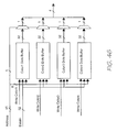
- the double-sided version of CePrint contains two printheads which operate in parallel. These printheads are fed by separate data paths, each of which replicates the logic found in the single- sided version of CePrint.
- the double- sided version has a correspondingly faster connection to the host processor (3MB/s).
- Table 1 gives a summary product specification of the single-sided and double-sided versions of the CePrint unit.
- Table 1 gives a summary product specification of the single-sided and double-sided versions of the CePrint unit.
- Table 1 gives a summary product specification of the single-sided and double-sided versions of the CePrint unit.
- Table 1 gives a summary product specification of the single-sided and double-sided versions of the CePrint unit.
- Table 1. CePrint Specification single-sided version double-sided version dot pitch 1600 dpi paper standard A4 / Letter paper tray capacity 150 sheets print speed 30 pages per minute 60 pages per minute, 30 sheets per minute warm-up time nil first print time 2-6 seconds subsequent prints 2 seconds / sheet color model 32-bit CMYK process color printable area full page (full edge bleed) printhead page width Memjet with 54,400 nozzles dual printheads print method self-cleaning transfer roller, titanium nitride (TiN) coated dual transfer rollers size (h x w x d) 40mm x
- a Memjet printhead produces 1600 dpi bi-level CMYK. On low-diffusion paper, each ejected drop forms an almost perfectly circular 22.5mm diameter dot. Dots are easily produced in isolation, allowing dispersed-dot dithering to be exploited to its fullest. Since the Memjet printhead is page-width and operates with a constant paper velocity, the four color planes are printed in perfect registration, allowing ideal dot-on-dot printing. Since there is consequently no spatial interaction between color planes, the same dither matrix is used for each color plane.
- a page layout may contain a mixture of images, graphics and text. Continuous-tone (contone) images and graphics are reproduced using a stochastic dispersed-dot dither. Unlike a clustered-dot (or amplitude-modulated) dither, a dispersed-dot (or frequency-modulated) dither reproduces high spatial frequencies (i.e. image detail) almost to the limits of the dot resolution, while simultaneously reproducing lower spatial frequencies to their full color depth, when spatially integrated by the eye.
- a stochastic dither matrix is carefully designed to be free of objectionable low- frequency patterns when tiled across the image. As such its size typically exceeds the minimum size required to support a number of intensity levels (i.e.
- CePrint uses a dither volume of size 64x64x3x8 bits.
- the volume provides an extra degree of freedom during the design of the dither by allowing a dot to change states multiple times through the intensity range, rather than just once as in a conventional dither matrix.
- CePrint prints A4 and Letter pages with full edge bleed.
- Corresponding page image sizes are set out in Table 2 for various spatial resolutions and color depths used in the following discussion. Note that the size of an A4 page exceeds the size of a Letter page, although the Letter page is wider. Page buffer requirements are therefore based on A4, while line buffer requirements are based on Letter. Table 2.
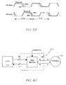
- the act of interrupting a Memjet-based printer during the printing of a page produces a visible discontinuity, so it is advantageous for the printer to receive the entire page before commencing printing, to eliminate the possibility of buffer underrun. Furthermore, if the transmission of the page from the host to the printer takes significant time in relation to the time it takes to print the page, then it is advantageous to provide two page buffers in the printer so that one page can be printed while the next is being received. If the transmission time of a page is less than its 2-second printing time, then double-buffering allows the full 30 pages/minute page rate of CePrint to be achieved.
- Figure 6 illustrates the sustained printing rate achievable with double-buffering in the printer, assuming 2-second page rendering and 2-second page transmission.
- the speed of this connection is 1-2MB/s (i.e. 2MB/s for parallel port, 1.5MB/s for USB, and 1MB/s for 10Base-T Ethernet).
- 2-second page transmission i.e. equal to the printing time
- this imposes a limit of 2-4MB on the size of the page image, i.e. a limit similar to that imposed by the size of the page buffer.
- the double- sided version requires a connection of twice that speed.
- Page rendering can be split between the host processor and printer in various ways.
- Some printers support a full page description language (PDL) such as Postscript, and contain correspondingly sophisticated renderers.
- PDL page description language
- Other printers provide special support only for rendering text, to achieve high text resolution. This usually includes support for built-in or downloadable fonts.
- an embedded renderer reduces the rendering burden on the host processor and reduces the amount of data transmitted from the host processor to the printer.
- These printers are more complex than they might be, and are often unable to provide full support for the graphics system of the host, through which application programs construct, render and print pages. They fail to exploit the possibly high performance of the host processor.
- CePrint relies on the host processor to render pages, i.e. contone images and graphics to the pixel level, and black text and graphics to the dot level.
- CePrint contains only a simple rendering engine which dithers the contone data and combines the results with any foreground bi- level black text and graphics. This strategy keeps the printer simple, and independent of any page description language or graphics system. It fully exploits the high performance expected in the host processor of a multimedia CE device.
- the downside of this strategy is the potentially large amount of data which must be transmitted from the host processor to the printer. We therefore use compression to reduce the page image size to the 3MB required to allow a sustained printing rate of 30 pages/minute.
- An 8.3" x 11.7" A4 page has a bi-level CMYK page image size of 119MBytes at 1600 dpi, and a contone CMYK pagesize of 59.3MB at 400 ppi.
- JPEG JPEG compression
- JPEG is inherently lossy, for compression ratios of 10:1 or less the loss is usually negligible.
- a contone resolution 267 ppi. This yields a contone CMYK pagesize of 25.5MB, a corresponding compression ratio of 8.5:1 to fit within the 3MB/page limit, and a contone to bi-level ratio of 1:6 in each dimension.
- a full page of black text (and/or graphics) rasterized at printer resolution (1600 dpi) yields a bi- level image of 29.6MB. Since rasterizing text at 1600 dpi places a heavy burden on the host processor for a small gain in quality, we choose to rasterize text at 800 dpi. This yields a bi- level image of 7.4MB, requiring a lossless compression ratio of less than 2.5:1 to fit within the 3MB/page limit. We achieve this using a two-dimensional bi-level compression scheme similar to the compression scheme used in Group 4 Facsimile.
- any combination of the two fits within the 3MB limit. If text lies on top of a background image, then the worst case is a compressed page image size approaching 6MB (depending on the actual text compression ratio). This fits within the printer's page buffer memory, but prevents double-buffering of pages in the printer, thereby reducing the printer's page rate by two-thirds, i.e. to 10 pages/minute.
- the host processor renders contone images and graphics to the pixel level, and black text and graphics to the dot level. These are compressed by different means and transmitted together to the printer.
- the printer contains two 3MB page buffers - one for the page being received from the host, and one for the page being printed.
- the printer expands the compressed page as it is being printed. This expansion consists of decompressing the 267 ppi contone CMYK image data, halftoning the resulting contone pixels to 1600 dpi bi-level CMYK dots, decompressing the 800 dpi bi- level black text data, and compositing the resulting bi-level black text dots over the corresponding bi-level CMYK image dots.
- CePrint is conceived as an OEM part designed for inclusion primarily in consumer electronics (CE) devices. Intended markets include televisions, VCRs, PhotoCD players, DVD players, Hi-fi systems, Web/Internet terminals, computer monitors, and vehicle consoles. It features a low-profile front panel and provides user access to paper and ink via an ejecting tray. It operates in a horizontal orientation under domestic environmental conditions.
- CePrint contains an ultra-compact print mechanism which yields an overall product height of 40mm for the single-sided version and 60mm for the double-sided version.
- CePrint is styled to be accommodated into all of the target market products and has minimum overall dimensions of 40mm high x 272mm wide x 416 mm deep.
- the only cosmetic part of the product is the front fascia and front tray plastics. These can be re-styled by a manufacturer if they wish to blend CePrint with a certain piece of equipment.
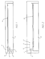
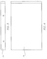
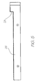
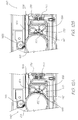
- FIGS 1 and 2 Front views of the two versions of CePrint or the printer are illustrated in Figures 1 and 2, respectively, of the drawings and are designated generally by the reference numeral 10. It is to be noted that, mechanically, both versions are the same, apart from the greater height of the double-sided version to accommodate a second print engine instead of a pinch roller. This will be described in greater detail below. Side and plan views of the single-sided version of CePrint are illustrated in Figures 3 and 4 respectively. The side view of of the double-sided version of CePrint is illustrated in Figure 5.
- CePrint 10 is a motorized A4/Letter paper tray with a removable ink cartridge and a Memjet printhead mechanism. It includes a front panel 12 housing a paper eject button 14, a power LED 16, an out-of-ink LED 18 and an out-of-paper LED 20. A paper tray 22 is slidably arranged relative to the front panel 12. When the paper tray 22 is in its "home” position, a paper output slot 24 is defined between the front panel 12 and the paper tray 22.
- the front panel 12 fronts a housing 26 containing the working parts of the printer 10.
- the housing 26 in the case of the double-sided version is stepped, at 28, towards the front panel 12 ( Figures 1 and 2) to accommodate the second print engine.
- the housing 26 covers a metal chassis 30 ( Figure 8), fascias, the (molded) paper tray 22, an ink cartridge 32 ( Figure 10), three motors, a flex PCB 34 ( Figure 8A), a rigid PCB 36 ( Figure 8) and various injection moldings and smaller parts to achieve a cost effective high volume product.
- the printer 10 is simple to operate, only requiring user interaction when paper or ink need replenishing as indicated by the front-panel LEDs 20 or 18, respectively.
- the paper handling mechanisms are similar to current printer applications and are therefore considered reliable.
- the tray 22 has a sensor which retracts the tray if the tray 22 is pushed. If the tray 22 jams on the way in, this is also sensed and the tray 22 is re-ejected. This allows the user to be lazy in operating the tray 22 by just pushing it to close and protects the unit from damage should the tray 22 get knocked while in the out position. It also caters for children sticking fingers in the tray 22 while closing.
- Ink is replaced by inserting a new cartridge 32 into the paper tray 22 ( Figure 8) and securing it by a cam lock lever mechanism.
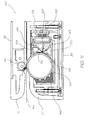
- the chassis 30 includes base metalwork 38 on which front roller wheels 40 of the paper tray 22 are slidable.
- a bracket 42 accommodates motors 44, 46 and 48 and gears 50 and 52 for ejecting the paper tray 22 and driving a paper pick-up roller 54.
- the flex PCB 34 ( Figure 8A) runs from the main PCB 36 via the motors 44, 46 and 48 to a contact molding 60 and a lightpipe area 62.
- An optical sensor on the flex PCB 34 allows the tray ejector motor 46 to retract the tray 22 independently of the eject button 14 if the tray 22 is pushed when in the out position by sensing a hole in a gear wheel 64 ( Figure 9). Similarly, the tray 22 is ejected if there is any stoppage during retraction.
- the contact molding 60 has a foam pad 66 that the flex PCB 34 is fixed onto and provides data and power contacts to the printhead and bus bars during printing.
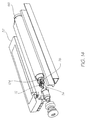
- a transfer roller 68 (Figure 11) has two end caps 69 (Figure 8A) that run in low friction bearing assemblies 70.
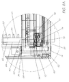
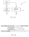
- One of the end caps 69 has an internal gear that acts on a small gear 72 ( Figure 14) which transfers power through a reduction gear 74 to a worm drive. This is reduced further via another gear to a motor worm drive 76 mounted on an output shaft of a stepper motor 124 arranged within the transfer roller 68.
- This solution for a motor drive assembly that is housed inside the transfer roller 68 saves space for future designs and mounts onto a small chassis 78 ( Figure 8A) that is attached to ink connector moldings 80, 82.
- An ink connector 84 has four pins 86 with an ejector plate 88 and springs 90 that interfaces with the ink cartridge 32 (Figure 10).
- the ink cartridge 32 is accessed via a cam lock lever and spring 92 ( Figure 8).
- the ink is conducted through molded channels into a flexible four-channel hose connector 94 that interfaces with a printhead cartridge end cap 96.
- the other end of the printhead cartridge has a different flexible sealing connector 98 ( Figure 8) on the end cap to allow ink to be drawn through the cartridge during assembly and effectively charge the unit and ink connector with ink in a sealed environment.
- the printhead and ink connector assemblies are mounted directly into the paper tray 22.
- the paper tray 22 has several standard paper handling components, namely a metal base channel 100 ( Figure 8) with low friction pads 102, sprung by two compression springs 104 and two metal paper guides 106 with arms 108 secured by rivets.
- the paper is aligned to one side of the tray 22 by a spring steel clip 110.
- the tray 22 is normally configured to take A4 paper, but Letter size paper is accommodated by relocating one of the paper guide assemblies 106 and clipping a plate into the paper tray 22 to provide a rear stop.
- the paper tray 22 can accommodate up to 150 sheets.
- the metal base channel 100 is pushed down and is latched using a tray lock molding 112 and a return spring 114.
- the tray lock molding 112 is unlatched by hitting a metal return 116 in the base metalwork 38 ( Figure 9).
- the printer 10 is now ready to print.
- the paper pick-up roller 54 is driven by a small drive gear 118 that meshes with another drive gear 50 and a normal motor 44.
- the roller 54 is located to the base metalwork 38 ( Figure 9) by two heat staked retainer moldings 120 ( Figure 8).
- a small molding on the end of the pick-up roller 54 acts with a sensor on the flex PCB 34 to accurately position the pick-up roller 54 in a parked position so that paper and tray 22 can be withdrawn without touching it when ejecting.
- This accurate positioning also allows the roller 54 to feed the sheet to the transfer roller 68 ( Figure 10) with a fixed number of revolutions.
- An optical sensor 122 mounted into the housing 26 finds the start of each sheet and engages a transfer motor 124 ( Figure 14), so there is no problem if for example a sheet has moved forward of the roller during any strange operations.
- the main PCB 36 is mounted onto the base metalwork 38 via standard PCB standoffs 126 and is fitted with a data connector 128 and a DC connector 130.
- the front panel 12 is mounted onto the base metalwork 38 using snap details and a top metal cover 132 completes the overall product with RFI/EMI integrity via four fixings 134.
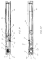
- the print engine is shown in greater detail in Figure 1 and is designated generally by the reference numeral 140.
- the Memjet printhead assembly is, in turn, designated by the reference numeral 142. This represents one of the four possible ways to deploy the Memjet printhead 143 in conjunction with the ink cartridge 32 in a product such as CePrint 10:
- the Memjet printhead 143 prints onto the titanium nitride (TiN) coated transfer roller 68 which rotates in an anticlockwise direction to transfer the image onto a sheet of paper 144.
- the paper 144 is pressed against the transfer roller 68 by a spring-loaded rubber coated pinch roller 145 in the case of the single-sided version.
- the paper 144 is pressed against one of the transfer rollers 68 under the action of the opposite transfer roller 68.
- the transfer roller 68 continues past a cleaning sponge 146 and finally a rubber wiper 148.
- the sponge 146 and the wiper 148 form a cleaning station for cleaning the surface of the transfer roller 68.
- the printhead assembly 142 While operational, the printhead assembly 142 is held off the transfer roller 68 by a solenoid 150 as shown in Figure 12B. When not operational, the printhead assembly 142 is parked against the transfer roller 68 as shown in Figure 12A. The printhead's integral elastomeric seal 152 seals the printhead assembly 142 and prevents the Memjet printhead 143 from drying out.
- the relationship between the ink cartridge 32, printhead assembly 142 and the transfer roller 68 is shown in greater detail in Figures 15 and 16 of the drawings.
- the ink cartridge has four reservoirs 154, 156, 158 and 160 for cyan, magenta, yellow and black ink respectively.
- Each reservoir 154-160 is in flow communication with a corresponding reservoir 164-170 in the printhead assembly 142.
- These reservoirs supply ink to a Memjet printhead chip 143 ( Figure 16) via an ink filter 174.
- the elastomeric capping seal 152 is arranged on both sides of the printhead chip 143 to assist in sealing when the printhead assembly 142 is parked against the transfer roller 68.
- Power is supplied to the solenoid via busbars 176.
- This section describes the printer control protocol used between a host and CePrint 10. It includes control and status handling as well as the actual page description.
- the printer control protocol defines the format and meaning of messages exchanged by the host processor and the printer 10.
- the control protocol is defined independently of the transport protocol between the host processor and the printer 10, since the transport protocol depends on the exact nature of the connection.
- Each message consists of a 16-bit message code, followed by message-specific data which may be of fixed or variable size.
- Table 3 defines command messages sent by the host processor to the printer 10.
- Printer command messages command message description message code reset printer 1 Resets the printer to an idle state (i.e. ready and not printing). get printer status 2 Gets the current printer status.
- start document 3 Starts a new document.
- start page 4 Starts the description of a new output page.
- page band 5 Describes a band of the current output page.
- end page 6 Ends the description of the current output page.
- end document 7 Ends the current document.
- the reset printer command can be used to reset the printer to clear an error condition, and to abort printing.
- the start document command is used to indicate the start of a new document. This resets the printer's page count, which is used in the double-sided version to identify odd and even pages.
- the end document command is simply used to indicate the end of the document.
- the description of an output page consists of a page header which describes the size and resolution of the page, followed by one or more page bands which describe the actual page content.
- the page header is transmitted to the printer in the start page command.
- Each page band is transmitted to the printer in a page band command.
- the last page band is followed by an end page command.
- the page description is described in detail in Table 4.2.
- Table 4 defines response messages sent by the printer to the host processor. Table 4.
- Printer response messages response message message code description printer status 8 Contains the current printer status(as defined in Table 7).
- page error 9 Contains the most recent page error code(as defined in Table 8).
- a printer status message is normally sent in response to a get printer status command.
- the nature of the connection between the host processor and the printer may allow the printer to send unsolicited status messages to the host processor. Unsolicited status messages allow timely reporting of printer exceptions to the host processor, and thereby to the user, without requiring the host processor to poll the printer on a frequent basis.
- a page error message is sent in response to each start page, page band and end page command.
- Table 5 defines the format of the 16-bit printer status contained in the printer status message. Table 5.
- Printer status format field bit description ready 0 The printer is ready to receive a page. printing I The printer is printing. error 2 The printer is in an error state. paper tray missing 3 The paper tray is missing. paper tray empty 4 The paper tray is empty. ink cartridge missing 5 The ink cartridge is missing. ink cartridge empty 6 The ink cartridge is empty. ink cartridge error 7 The ink cartridge is in an error state. (reserved) 8-15 Reserved for future use.
- Table 6 defines page error codes which may be returned in a page error message. Table 6. Page error codes error code value description no error 0 No error. bad signature I The signature is not recognized. bad version 2 The version is not supported. bad parameter 3 A parameter is incorrect.
- CePrint 10 reproduces black at full dot resolution (1600 dpi), but reproduces contone color at a somewhat lower resolution using halftoning.
- the page description is therefore divided into a black layer and a contone layer.
- the black layer is defined to composite over the contone layer.
- the black layer consists of a bitmap containing a 1-bit opacity for each pixel.
- This black layer matte has a resolution which is an integer factor of the printer's dot resolution.
- the highest supported resolution is 1600 dpi, i.e. the printer's full dot resolution.
- the contone layer consists of a bitmap containing a 32-bit CMYK color for each pixel.
- This contone image has a resolution which is an integer factor of the printer's dot resolution.
- the highest supported resolution is 267 ppi, i.e. one-sixth the printer's dot resolution.
- the contone resolution is also typically an integer factor of the black resolution, to simplify calculations in the printer driver. This is not a requirement, however.
- the black layer and the contone layer are both in compressed form for efficient transmission over the low-speed connection to the printer.
- CePrint prints with full edge bleed using an 8.5" printhead. It imposes no margins and so has a printable page area which corresponds to the size of its paper (A4 or Letter).
- the target page size is constrained by the printable page area, less the explicit (target) left and top margins specified in the page description.
- each page description is complete and self-contained. There is no data transmitted to the printer separately from the page description to which the page description refers.
- the page description consists of a page header which describes the size and resolution of the page, followed by one or more page bands which describe the actual page content.
- Table 7 shows the format of the page header.
- Page header format field format description signature 16-bit integer Page header format signature. version 16-bit integer Page header format version number. structure size 16-bit integer Size of page header.
- target resolution (dpi) 16-bit integer Resolution of target page. This is always 1600 for CePrint.
- target page width 16-bit integer Width of target page, in dots.
- target page height 16-bit integer Height of target page, in dots.
- target left margin 16-bit integer Width of target left margin, in dots.
- target top margin 16-bit integer Height of target top margin, in dots.
- black scale factor 16-bit integer Scale factor from black resolution to target resolution (must be 2 or greater).
- the page header contains a signature and version which allow the printer to identify the page header format. If the signature and/or version are missing or incompatible with the printer, then the printer can reject the page.
- the page header defines the resolution and size of the target page.
- the black and contone layers are clipped to the target page if necessary. This happens whenever the black or contone scale factors are not factors of the target page width or height.
- the target left and top margins define the positioning of the target page within the printable page area.
- the black layer parameters define the pixel size of the black layer, and its integer scale factor to the target resolution.
- the contone layer parameters define the pixel size of the contone layer, and its integer scale factor to the target resolution.
- Table 8 shows the format of the page band header.
- Page band header format field format description signature 16-bit integer Page band header format signature. version 16-bit integer Page band header format version number. structure size 16-bit integer Size of page band header. black band height 16-bit integer Height of black band, in black pixels. black band data size 32-bit integer Size of black band data, in bytes. contone band height 16-bit integer Height of contone band, in contone pixels. contone band data size 32-bit integer Size of contone band data, in bytes.
- the black layer parameters define the height of the black band, and the size of its compressed band data.
- the variable-size black band data follows the fixed-size parts of the page band header.
- the contone layer parameters define the height of the contone band, and the size of its compressed page data.
- the variable-size contone band data follows the variable-size black band data.
- Table 9 shows the format of the variable-size compressed band data which follows the page band header.
- Page band data format field format description black band data EDRL bytestream Compressed bi-level black band data.
- contone band data JPEG bytestream Compressed contone CMYK band data.
- variable-size black band data and the variable-size contone band data are aligned to 8-byte boundaries.
- the size of the required padding is included in the size of the fixed-size part of the page band header structure and the variable-size black band data.
- the entire page description has a target size of less than 3MB, and a maximum size of 6MB, in accordance with page buffer memory in the printer.
- the following sections describe the format of the compressed black layer and the compressed contone layer.
- the Group 3 Facsimile compression algorithm losslessly compresses bi-level data for transmission over slow and noisy telephone lines.
- the bi-level data represents scanned black text and graphics on a white background, and the algorithm is tuned for this class of images (it is explicitly not tuned, for example, for halftoned bi- level images).
- the 1D Group 3 algorithm runlength-encodes each scanline and then Huffman-encodes the resulting runlengths. Runlengths in the range 0 to 63 are coded with terminating codes. Runlengths in the range 64 to 2623 are coded with make-up codes, each representing a multiple of 64, followed by a terminating code. Runlengths exceeding 2623 are coded with multiple make-up codes followed by a terminating code.
- the Huffman tables are fixed, but are separately tuned for black and white runs (except for make-up codes above 1728, which are common).
- the 2D Group 3 algorithm encodes a scanline as a set of short edge deltas (0, ⁇ 1, ⁇ 2, ⁇ 3) with reference to the previous scanline.
- the delta symbols are entropy-encoded (so that the zero delta symbol is only one bit long etc.)
- Edges within a 2D-encoded line which can't be delta-encoded are runlength-encoded, and are identified by a prefix. 1D- and 2D-encoded lines are marked differently. 1D-encoded lines are generated at regular intervals, whether actually required or not, to ensure that the decoder can recover from line noise with minimal image degradation.
- 2D Group 3 achieves compression ratios of up to 6:1.
- the Group 4 Facsimile algorithm losslessly compresses bi-level data for transmission over error-free communications lines (i.e. the lines are truly error- free, or error-correction is done at a lower protocol level).
- the Group 4 algorithm is based on the 2D Group 3 algorithm, with the essential modification that since transmission is assumed to be error-free, 1D-encoded lines are no longer generated at regular intervals as an aid to error-recovery.
- Group 4 achieves compression ratios ranging from 20:1 to 60:1 for the CCITT set of test images.
- the design goals and performance of the Group 4 compression algorithm qualify it as a compression algorithm for the bi- level black layer.
- its Huffman tables are tuned to a lower scanning resolution (100-400 dpi), and it encodes runlengths exceeding 2623 awkwardly.
- 800 dpi our maximum runlength is currently 6400.
- a Group 4 decoder core might be available for use in the printer controller chip (Section 7), it might not handle runlengths exceeding those normally encountered in 400 dpi facsimile applications, and so would require modification.
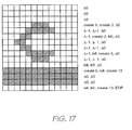
- the edge delta and runlength (EDRL) compression format is based loosely on the Group 4 compression format and its precursors.
- EDRL uses three kinds of symbols, appropriately entropy-coded. These are create edge, kill edge, and edge delta. Each line is coded with reference to its predecessor. The predecessor of the first line is defined to a line of white. Each line is defined to start off white. If a line actually starts of black (the less likely situation), then it must define a black edge at offset zero. Each line must define an edge at its left-hand end, i.e. at offset page width.
- An edge can be coded with reference to an edge in the previous line if there is an edge within the maximum delta range with the same sense (white-to-black or black-to-white). This uses one of the edge delta codes. The shorter and likelier deltas have the shorter codes.
- the maximum delta range ( ⁇ 2) is chosen to match the distribution of deltas for typical glyph edges. This distribution is mostly independent of point size. A typical example is given in Table 10. Table 10. Edge delta distribution for 10 point Times at 800 dpi
- An edge can also be coded using the length of the run from the previous edge in the same line. This uses one of the create edge codes for short (7-bit) and long (13-bit) runlengths. For simplicity, and unlike Group 4, runlengths are not entropy-coded. In order to keep edge deltas implicitly synchronized with edges in the previous line, each unused edge in the previous line is 'killed' when passed in the current line. This uses the kill edge code. The end-of-page code signals the end of the page to the decoder.
- runlengths are specifically chosen to support 800 dpi A4/Letter pages. Longer runlengths could be supported without significant impact on compression performance. For example, if supporting 1600 dpi compression, the runlengths should be at least 8-bit and 14-bit respectively. A general-purpose choice might be 8-bit and 16-bit, thus supporting up to 40" wide 1600 dpi pages.
- Figure 17 shows a simple encoding example. Note that the common situation of an all-white line following another all-white line is encoded using a single bit ( ⁇ 0), and an all-black line following another all-black line is encoded using two bits ( ⁇ 0, ⁇ 0).
- the following is a simple algorithm for producing the EDRL encoding of a line with reference to its predecessor.
- Table 12 shows the compression performance of Group 4 and EDRL on the CCITT test documents used to select the Group 4 algorithm. Each document represents a single page scanned at 400 dpi. Group 4's superior performance is due to its entropy-coded runlengths, tuned to 400 dpi features. Table 12. Group 4 and EDRL compression performance on standard CCITTT documents at 400 dpi CCITT document number Group 4 compression ratio EDRL compression ratio 1 29.1 21.6 2 49.9 41.3 3 17.9 14.1 4 7.3 5.5 5 15.8 12.4 6 31.0 25.5 7 7.4 5.3 8 26.7 23.4
- Magazine text is typically typeset in a typeface with serifs (such as Times) at a point size of 10. At this size an A4/Letter page holds up to 14,000 characters, though a typical magazine page holds only about 7,000 characters. Text is seldom typeset at a point size smaller than 5. At 800 dpi, text cannot be meaningfully rendered at a point size lower than 2 using a standard typeface. Table 13 illustrates the legibility of various point sizes. Table 13. Text at different point sizes point size sample text (in Times) 2 The quick brown fox jumps over the lazy dog. 3 The quick brown fox jumps over the lazy dog. 4 The quick brown fox jumps over the lazy dog. 5 The quick brown fox jumps over the lazy dog. 6 The quick brown fox jumps over the lazy dog. 7 The quick brown fox jumps over the lazy dog 8 The quick brown fox jumps over the lazy dog. 9 The quick brown fox jumps over the lazy dog. 10 The quick brown fox jumps over the lazy dog.
- Table 14 shows Group 4 and EDRL compression performance on pages of text of varying point sizes, rendered at 800 dpi. Note that EDRL achieves the required compression ratio of 2.5 for an entire page of text typeset at a point size of 3. The distribution of characters on the test pages is based on English-language statistics. Table 14.
- EDRL slightly outperforms Group 4, simply because Group 4's runlength codes are tuned to 400 dpi.
- the JPEG compression algorithm lossily compresses a contone image at a specified quality level. It introduces imperceptible image degradation at compression ratios below 5:1, and negligible image degradation at compression ratios below 10:1.
- JPEG typically first transforms the image into a color space which separates luminance and chrominance into separate color channels. This allows the chrominance channels to be subsampled without appreciable loss because of the human visual system's relatively greater sensitivity to luminance than chrominance. After this first step, each color channel is compressed separately.
- the image is divided into 8x8 pixel blocks. Each block is then transformed into the frequency domain via a discrete cosine transform (DCT).
- DCT discrete cosine transform
- This transformation has the effect of concentrating image energy in relatively lower- frequency coefficients, which allows higher-frequency coefficients to be more crudely quantized.
- This quantization is the principal source of compression in JPEG. Further compression is achieved by ordering coefficients by frequency to maximize the likelihood of adjacent zero coefficients, and then runlength-encoding runs of zeroes. Finally, the runlengths and non-zero frequency coefficients are entropy coded. Decompression is the inverse process of compression.
- the CMYK contone layer is compressed to an interleaved color JPEG bytestream.
- the interleaving is required for space-efficient decompression in the printer, but may restrict the decoder to two sets of Huffman tables rather than four (i.e. one per color channel). If luminance and chrominance are separated, then the luminance channels can share one set of tables, and the chrominance channels the other set.
- CMY is converted to YCrCb and Cr and Cb are duly subsampled.
- K is treated as a luminance channel and is not subsampled.
- the JPEG bytestream is complete and self-contained. It contains all data required for decompression, including quantization and Huffman tables.
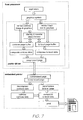
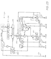
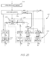
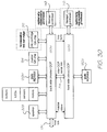
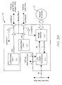
- a printer controller 178 ( Figure 18) consists of the CePrint central processor (CCP) chip 180, a 64MBit RDRAM 182, and a master QA chip 184.
- CCP CePrint central processor
- the CCP 180 contains a general-purpose processor 181 and a set of purpose-specific functional units controlled by the processor via a processor bus 186. Only three functional units are non-standard - an EDRL expander 188, a halftoner/compositor 190, and a printhead interface 192 which controls the Memjet printhead 143.
- Page expansion and printing proceeds as follows.
- a page description is received from the host via a host interface 194 and is stored in main memory 182.
- 6MB of main memory 182 is dedicated to page storage. This can hold two pages each not exceeding 3MB, or one page up to 6MB. If the host generates pages not exceeding 3MB, then the printer operates in streaming mode - i.e. it prints one page while receiving the next. If the host generates pages exceeding 3MB, then the printer operates in single-page mode - i.e. it receives each page and prints it before receiving the next. If the host generates pages exceeding 6MB then they are rejected by the printer. In practice the printer driver prevents this from happening.
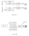
- a page consists of two parts - the bi- level black layer, and the contone layer. These are compressed in distinct formats - the bi- level black layer in EDRL format, the contone layer in JPEG format.
- the first stage of page expansion consists of decompressing the two layers in parallel.
- the bi- level layer is decompressed by the EDRL expander unit 188, the contone layer by a JPEG decoder 196.
- the second stage of page expansion consists of halftoning the contone CMYK data to bi-level CMYK, and then compositing the bi- level black layer over the bi-level CMYK layer.
- the halftoning and compositing is carried out by the halftoner/compositor unit 190.
- the composited bi- level CMYK image is printed via the printhead interface unit 192, which controls the Memjet printhead 143.
- the Memjet printhead 143 prints at high speed, the paper 144 must move past the printhead 143 at a constant velocity. If the paper 144 is stopped because data cannot be fed to the printhead 143 fast enough, then visible printing irregularities will occur. It is therefore important to transfer bi- level CMYK data to the printhead interface 192 at the required rate.
- a fully-expanded 1600 dpi bi-level CMYK page has an image size of 119MB. Because it is impractical to store an expanded page in printer memory, each page is expanded in real time during printing. Thus the various stages of page expansion and printing are pipelined.
- the page expansion and printing data flow is described in Table 15. The aggregate traffic to/from main memory via an interface 198 of 182MB/s is well within the capabilities of current technologies such as Rambus. Table 15.
- Each stage communicates with the next via a shared FIFO in main memory 182.
- Each FIFO is organized into lines, and the minimum size (in lines) of each FIFO is designed to accommodate the output window (in lines) of the producer and the input window (in lines) of the consumer.
- Inter-stage main memory buffers are described in Table 16. The aggregate buffer space usage of 6.3MB leaves 1.7MB free for program code and scratch memory (out of the 8MB available). Table 16.
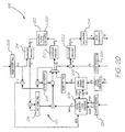
- the overall data flow, including FIFOs, is illustrated in Figure 19.
- Contone page decompression is carried out by the JPEG decoder 196.
- Bi- level page decompression is carried out by the EDRL expander 188.
- Halftoning and compositing is carried out by the halftoner/compositor unit190.
- Each functional unit contains one or more on-chip input and/or output FIFOs.
- Each FIFO is allocated a separate channel in a multi-channel DMA controller 200.
- the DMA controller 200 handles single-address rather than double-address transfers, and so provides a separate request/acknowledge interface for each channel.
- Each functional unit stalls gracefully whenever an input FIFO is exhausted or an output FIFO is filled.
- the processor 181 programs each DMA transfer.
- the DMA controller 200 generates the address for each word of the transfer on request from the functional unit connected to the channel.
- the functional unit latches the word onto or off the data bus 186 when its request is acknowledged by the DMA controller 200.
- the DMA controller 200 interrupts the processor 181 when the transfer is complete, thus allowing the processor 181 to program another transfer on the same channel in a timely fashion.
- processor 181 will program another transfer on a channel as soon as the corresponding main memory FIFO is available (i.e. non-empty for a read, non-full for a write).
- the granularity of channel servicing implemented in the DMA controller 200 depends somewhat on the latency of main memory 182.
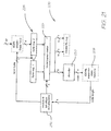
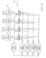
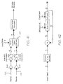
- the EDRL expander unit (EEU) 188 is shown in greater detail in Figure 20.
- the unit 188 decompresses an EDRL-compressed bi- level image.
- the input to the EEU 188 is an EDRL bitstream.
- the output from the EEU is a set of bi- level image lines, scaled horizontally from the resolution of the expanded bi-level image by an integer scale factor to 1600 dpi.
- the EEU 188 proceeds until it detects an end-of-page code in the EDRL bitstream, or until it is explicitly stopped via its control register.
- the EEU 188 relies on an explicit page width to decode the bitstream. This must be written to a page width register 202 prior to starting the EEU 188.
- the scaling of the expanded bi- level image relies on an explicit scale factor. This must be written to a scale factor register 204 prior to starting the EEU 188. Table 17. EDRL expander control and configuration registers register width description start 1 Start the EEU. stop 1 Stop the EEU. page width 13 Page width used during decoding to detect end-of line. scale factor 4 Scale factor used during scaling of expanded image.
- the EDRL compression format is described in Section 6.2.3.2. It represents a bi-level image in terms of its edges. Each edge in each line is coded relative to an edge in the previous line, or relative to the previous edge in the same line. No matter how it is coded, each edge is ultimately decoded to its distance from the previous edge in the same line. This distance, or runlength, is then decoded to the string of one bits or zero bits which represent the corresponding part of the image.
- the decompression algorithm is defined in Section 6.2.3.2.
- the EEU 188 consists of a bitstream decoder 206, a state machine 208, edge calculation logic 210, two runlength decoders 212, and a runlength (re)encoder 214.
- the bitstream decoder 206 decodes an entropy-coded codeword from the bitstream and passes it to the state machine 208.
- the state machine 208 returns the size of the codeword to the bitstream decoder 206, which allows the decoder 206 to advance to the next codeword.
- the state machine 208 uses the bitstream decoder 206 to extract the corresponding runlength from the bitstream.
- the state machine 208 controls the edge calculation logic 210 and runlength decoding/encoding as defined in Table 19.
- the edge calculation logic 210 is quite simple.
- the current edge offset in the previous (reference) and current (coding) lines are maintained in a reference edge register 216 and edge register 218 respectively.
- the runlength associated with a create edge code is output directly to the runlength decoder 212.1, and is added to the current edge.
- a delta code is translated into a runlength by adding the associated delta to the reference edge and subtracting the current edge.
- the generated runlength is output to the runlength decoder 212.1, and is added to the current edge.
- the next runlength is extracted from the runlength encoder 214 and added to the reference edge.
- a kill edge code simply causes the current reference edge to be skipped. Again the next runlength is extracted from the runlength encoder 214 and added to the reference edge.
- the edge calculation logic 210 Each time the edge calculation logic 210 generates a runlength representing an edge, it is passed to the runlength decoder 212.1. While the runlength decoder 212.1 decodes the run it generates a stall signal to the state machine 208. Since the runlength decoder 212 is slower than the edge calculation logic 210, there is not much point in decoupling it.
- the expanded line accumulates in a line buffer 220 large enough to hold an 8.5" 800 dpi line (850 bytes).
- the previously expanded line is also buffered in a buffer 222. It acts as a reference for the decoding of the current line.
- the previous line is re-encoded as runlengths on demand. This is less expensive than buffering the decoded runlengths of the previous line, since the worst case is one 13-bit runlength for each pixel (20KB at 1600 dpi).
- the runlength encoder 214 encodes the run it generates a stall signal to the state machine 208.
- the runlength encoder 214 uses the page width to detect end-online.
- the (current) line buffer 220 and the previous line buffer 222 are concatenated and managed as a single FIFO to simplify the runlength encoder 214.
- the second runlength decoder 212.2 decodes the output runlength to a line buffer 224 large enough to hold an 8.5" 1600 dpi line (1700 bytes).
- the runlength passed to this output runlength decoder 212.2 is multiplied by the scale factor from the register 204, so this decoder 212.2 produces 1600 dpi lines.
- the line is output scale factor times through the output pixel FIFO. This achieves the required vertical scaling by simple line replication.
- the EEU 188 could be designed with edge smoothing integrated into its image scaling. A simple smoothing scheme based on template- matching can be very effective. This would require a multi-line buffer between the low-resolution runlength decoder and the smooth scaling unit, but would eliminate the high-resolution runlength decoder.
- the EDRL stream decoder 206 ( Figure 21) decodes entropy-coded EDRL codewords in the input bitstream. It uses a two-byte input buffer 226 viewed through a 16-bit barrel shifter 228 whose left (most significant) edge is always aligned to a codeword boundary in the bitstream. A decoder 230 connected to the barrel shifter 228 decodes a codeword according to Table 18, and supplies the state machine 208 with the corresponding code. Table 18.
- the state machine 208 in turn outputs the length of the code. This is added, modulo-8, by an accumulator 232 to the current codeword bit offset to yield the next codeword bit offset.
- the bit offset in turn controls the barrel shifter 228. If the codeword bit offset wraps, then the carry bit controls the latching of the next byte from the input FIFO. At this time byte 2 is latched to byte 1, and the FIFO output is latched to byte 2. It takes two cycles of length 8 to fill the input buffer. This is handled by starting states in the state machine 208.
- the EDRL expander state machine 208 controls the edge calculation and runlength expansion logic in response to codes supplied by the EDRL stream decoder 206. It supplies the EDRL stream decoder 206 with the length of the current codeword and supplies the edge calculation logic 210 with the delta value associated with the current delta code.
- the state machine 206 also responds to start and stop control signals from a control register 234 ( Figure 20), and the end-of-line (EOL) signal from the edge calculation logic 210.
- the state machine 208 also controls the multi-cycle fetch of the runlength associated with a create edge code. Table 19.
- EDRL expander state machine input signal input code current state next state code len delta actions start - stopped starting 8 - - - - starting idle 8 - - stop - - stopped 0 - reset RL decoders and FIFOs EOL - - EOL 1 0 - reset RL encoder; reset RL decoders; reset ref. edge and edge - - EOL 1 idle RL encoder ⁇ ref. RL; ref. edge + ref. RL ⁇ ref. edge - ⁇ 0 idle idle 1 0 edge - ref. edge + delta ⁇ RL; edge + RL ⁇ edge; RL ⁇ RL decoder; RL encoder ⁇ ref. RL; ref. edge + ref. RL ⁇ ref.
- the runlength decoder 212 expands a runlength into a sequence of zero bits or one bits of the corresponding length in the output stream.
- the first run in a line is assumed to be white (color 0).
- Each run is assumed to be of the opposite color to its predecessor. If the first run is actually black (color 1), then it must be preceded by a zero-length white run.
- the runlength decoder 212 keeps track of the current color internally.
- the runlength decoder 212 appends a maximum of 8 bits to the output stream every clock. Runlengths are typically not an integer multiple of 8, and so runs other than the first in an image are typically not byte-aligned.
- the runlength decoder 212 maintains, in a byte space register 236 ( Figure 22), the number of bits available in the byte currently being built. This is initialized to 8 at the beginning of decoding, and on the output of every byte.
- the decoder 212 starts outputting a run of bits as soon as the next run line 248 latches a non-zero value into a runlength register 238.
- the decoder 212 effectively stalls when the runlength register 238 goes to zero.
- a number of bits of the current color are shifted into an output byte register 240 each clock.
- the current color is maintained in a 1-bit color register 242.
- the number of bits actually output is limited by the number of bits left in the runlength, and by the number of spare bits left in the output byte.
- the number of bits output is subtracted from the runlength and the byte space. When the runlength goes to zero it has been completely decoded, although the trailing bits of the run may still be in the output byte register 240, pending output. When the byte space goes to zero the output byte is full and is appended to the output stream.
- a 16-bit barrel shifter 244, the output byte register 240 and the color register 242 together implement an 8-bit shift register which can be shifted multiple bit positions every clock, with the color as the serial input.
- An external reset line 246 is used to reset the runlength decoder 212 at the start of a line.
- An external next run line 248 is used to request the decoding of a new runlength. It is accompanied by a runlength on an external runlength line 250. The next run line 248 should not be set on the same clock as the reset line 246. Because next run inverts the current color, the reset of the color sets it to one, not zero.
- An external flush line 252 is used to flush the last byte of the run, if incomplete. It can be used on a line-by- line basis to yield byte-aligned lines, or on an image basis to yield a byte-aligned image.
- An external ready line 254 indicates whether the runlength decoder 212 is ready to decode a runlength. It can be used to stall the external logic.
- the runlength encoder 214 detects a run of zero or one bits in the input stream.
- the first run in a line is assumed to be white (color 0).
- Each run is assumed to be of the opposite color to its predecessor. If the first run is actually black (color 1), then the runlength encoder 214 generates a zero-length white run at the start of the line.
- the runlength decoder keeps track of the current color internally.
- the runlength encoder 214 reads a maximum of 8 bits from the input stream every clock. It uses a two-byte input buffer 256 ( Figure 23) viewed through a 16-bit barrel shifter 258 whose left (most significant) edge is always aligned to the current position in the bitstream. An encoder 260 connected to the barrel shifter 258 encodes an 8-bit (partial) runlength according to Table 20. The 8-bit runlength encoder 260 uses the current color to recognize runs of the appropriate color.
- the 8-bit runlength generated by the 8-bit runlength encoder 260 is added to the value in a runlength register 262.
- the 8-bit runlength encoder 260 recognizes the end of the current run it generates an end-of-run signal which is latched by a ready register 264.
- the output of the ready register 264 indicates that the encoder 214 has completed encoding the current runlength, accumulated in the runlength register 262.
- the output of the ready register 264 is also used to stall the 8-bit runlength encoder 260.
- the 8-bit runlength encoder 260 outputs a zero-length run and a zero end-of-run signal, effectively stalling the entire runlength encoder 214. Table 20.
- the output of the 8-bit runlength encoder 260 is limited by the remaining page width.
- the actual 8-bit runlength is subtracted from the remaining page width, and is added to a modulo-8 bit position accumulator 266 used to control the barrel shifter 258 and clock the byte stream input.
- An external reset line 268 is used to reset the runlength encoder 214 at the start of a line. It resets the current color and latches a page width signal on line 270 into a page width register 272.
- An external next run line 274 is used to request another runlength from the runlength encoder 214. It inverts the current color, and resets the runlength register 262 and ready register 264.
- An external flush line 276 is used to flush the last byte of the run, if incomplete. It can be used on a line-by-line basis to process byte-aligned lines, or on an image basis to process a byte-aligned image.
- An external ready line 278 indicates that the runlength encoder 214 is ready to encode a runlength, and that the current runlength is available on a runlength line 280. It can be used to stall the external logic.
- the EEU 188 has an output rate of 124M 1-bit black pixels/s.
- the core logic generates one runlength every clock.
- the runlength decoders 212 and the runlength encoder 214 generate/consume up to 8 pixels (bits) per clock.
- One runlength decoder 212.1 and the runlength encoder 214 operate at quarter resolution (800 dpi).
- the other runlength decoder 212.2 operates at full resolution (1600 dpi).
- a worst-case bi-level image consisting of a full page of 3 point text converts to approximately 6M runlengths at 800 dpi (the rendering resolution). At 1600 dpi (the horizontal output resolution) this gives an average runlength of about 20. Consequently about 40% of 8-pixel output bytes span two runs and so require two clocks instead of one.
- Output lines are replicated vertically to achieve a vertical resolution of 1600 dpi. When a line is being replicated rather than generated it has a perfect efficiency of 8 pixels per clock, thus the overhead is halved to 20%.
- the full-resolution runlength decoder in the output stage of the EEU 188 is the slowest component in the EEU 188.
- the minimum clock speed of the EEU 188 is therefore dictated by the output pixel rate of the EEU (124Mpixels/s), divided by the width of the runlength decoder (8), adjusted for its worst-case overhead (20%). This gives a minimum speed of about 22MHz.
- the JPEG decoder 196 ( Figure 24) decompresses a JPEG-compressed CMYK contone image.
- the input to the JPEG decoder 196 is a JPEG bitstream.
- the output from the JPEG decoder 196 is a set of contone CMYK image lines.
- the JPEG decoder 196 When decompressing, the JPEG decoder 196 writes its output in the form of 8x8 pixel blocks. These are sometimes converted to full-width lines via an page width x 8 strip buffer closely coupled with the codec. This would require a 67KB buffer. We instead use 8 parallel pixel FIFOs 282 with shared bus access and 8 corresponding DMA channels, as shown in Figure 24.
- the JPEG decoder 196 has an output rate of 3.5M 32-bit CMYK pixels/s.
- the required clock speed of the decoder depends on the design of the decoder.
- the halftoner/compositor unit (HCU) 190 ( Figure 25) combines the functions of halftoning the contone CMYK layer to bi- level CMYK, and compositing the black layer over the halftoned contone layer.
- the input to the HCU 190 is an expanded 267 ppi CMYK contone layer, and an expanded 1600 dpi black layer.
- the output from the HCU 190 is a set of 1600 dpi bi-level CMYK image lines.
- the HCU 190 proceeds until it detects an end-of-page condition, or until it is explicitly stopped via its control register 284.
- the HCU 190 generates a page of dots of a specified width and length.
- the width and length must be written to page width and page length registers of the control registers 284 prior to starting the HCU 190.
- the page width corresponds to the width of the printhead.
- the page length corresponds to the length of the target page.
- the HCU 190 generates target page data between specified left and right margins relative to the page width.
- the positions of the left and right margins must be written to left margin and right margin registers of the control registers 284 prior to starting the HCU 190.
- the distance from the left margin to the right margin corresponds to the target page width.
- the HCU 190 consumes black and contone data according to specified black and contone page widths. These page widths must be written to black page width and contone page width registers of the control registers 284 prior to starting the HCU 190 .
- the HCU 190 clips black and contone data to the target page width. This allows the black and contone page widths to exceed the target page width without requiring any special end-of- line logic at the input FIFO level.
- the HCU 190 scales contone data to printer resolution both horizontally and vertically based on a specified scale factor. This scale factor must be written to a contone scale factor register of the control registers 284 prior to starting the HCU 190.
- Halftoner/compositor control and configuration registers register width description start 1 Start the HCU. stop 1 Stop the HCU. page width 14 Page width of printed page, in dots. This is the number of dots which have to be generated for each line. left margin 14 Position of left margin, in dots. right margin 14 Position of right margin, in dots. page length 15 Page length of printed page, in dots. This is the number of lines which have to be generated for each page. black page width 14 Page width of black layer, in dots. Used to detect the end of a black line. contone page width 14 Page width of contone layer, in dots. Used to detect the end of a contone line. contone scale factor 4 Scale factor used to scale contone data to bi-level resolution.
- the consumer of the data produced by the HCU 190 is the printhead interface 192.
- the printhead interface 192 requires bi-level CMYK image data in planar format, i.e. with the color planes separated. Further, it also requires that even and odd pixels are separated.
- the output stage of the HCU 190 therefore uses 8 parallel pixel FIFOs 286, one each for even cyan, odd cyan, even magenta, odd magenta, even yellow, odd yellow, even black, and odd black.
- An input contone CMYK FIFO 288 is a full 9KB line buffer.
- the line is used contone scale factor times to effect vertical up-scaling via line replication. FIFO write address wrapping is disabled until the start of the last use of the line.
- An alternative is to read the line from main memory contone scale factor times, increasing memory traffic by 44MB/s, but avoiding the need for the on-chip 9KB line buffer.
- a multi-threshold dither unit 290 is shown in Figure 27 of the drawings.
- a general 256-layer dither volume provides great flexibility in dither cell design, by decoupling different intensity levels.
- General dither volumes can be large - a 64x64x256 dither volume, for example, has a size of 128KB. They are also inefficient to access since each color component requires the retrieval of a different bit from the volume. In practice, there is no need to fully decouple each layer of the dither volume.
- Each dot column of the volume can be implemented as a fixed set of thresholds rather than 256 separate bits. Using three 8-bit thresholds, for example, only consumes 24 bits.
- n thresholds define n +1 intensity intervals, within which the corresponding dither cell location is alternately not set or set.
- the contone pixel value being dithered uniquely selects one of the n + 1 intervals, and this determines the value of the corresponding output dot.
- the three thresholds form a convenient 24-bit value which can be retrieved from the dither cell ROM in one cycle. If dither cell registration is desired between color planes, then the same triple-threshold value can be retrieved once and used to dither each color component. If dither cell registration is not desired, then the dither cell can be split into four subcells and stored in four separately addressable ROMs from which four different triple-threshold values can be retrieved in parallel in one cycle. Using the addressing scheme shown below, the four color planes share the same dither cell at vertical and/or horizontal offsets of 32 dots from each other.
- Each triple-threshold unit 292 converts a triple-threshold value and an intensity value into an interval and thence a one or zero bit.
- the triple-thresholding rules are shown in Table 22. The corresponding logic is shown in Figure 28. Table 22. Triple-thresholding rules interval output V ⁇ T 1 0 T 1 ⁇ V ⁇ T 2 1 T 2 ⁇ V ⁇ T 3 0 T 3 ⁇ V 1
- a composite unit 294 of the HCU 190 composites a black layer dot over a halftoned CMYK layer dot. If the black layer opacity is one, then the halftoned CMY is set to zero.
- a clock enable generator 296 of the HCU 190 generates enable signals for clocking the contone CMYK pixel input, the black dot input, and the CMYK dot output.
- the contone pixel input buffer is used as both a line buffer and a FIFO.
- Each line is read once and then used contone scale factor times.
- FIFO write address wrapping is disabled until the start of the final replicated use of the line, at which time the clock enable generator 296 generates a contone line advance enable signal which enables wrapping.
- the clock enable generator 296 also generates an even signal which is used to select the even or odd set of output dot FIFOs, and a margin signal which is used to generate white dots when the current dot position is in the left or right margin of the page.
- the clock enable generator 296 uses a set of counters.
- the internal logic of the counters is defined in Table 24.
- the logic of the clock enable signals is defined in Table 25.
- the HCU 190 has an output rate of 124M 4-bit CMYK pixels/s. Since it generates one pixel per clock, it must be clocked at at least 124MHz.
- CePrint 10 uses an 8.5" CMYK Memjet printhead 143, as described in Section 9.
- the printhead consists of 17 segments arranged in 2 segment groups.
- the first segment group contains 9 segments, and the second group contains 8 segments.
- the printhead interface 192 is a standard Memjet printhead interface, as described in Section 10, configured with the following operating parameters:
- CePrint 10 prints an 8.3" x 11.7" page in 2 seconds.
- the printhead 143 must therefore print 18,720 lines (11.7" x 1600 dpi) in 2 seconds, which yields a line time of about 107 ⁇ s.
- a single Print Cycle and a single Load Cycle must both complete within this time.
- the paper 144 must advance by about 16 ⁇ m in the same time.
- the Memjet printhead 143 can print an entire line in 100 ⁇ s. Since all segments fire at the same time 544 nozzles are fired simultaneously with each firing pulse. This leaves 7 ⁇ s for other tasks between each line.
- the printhead interface 192 has a nominal pixel rate of 124M 4-bit CMYK pixels/s. However, because it is only active for 100 ⁇ s out of every 107 ⁇ s, it must be clocked at at least 140MHz. This can be increased to 144MHz to make it an integer multiple of the printhead speed.
- the processor 181 runs the control program which synchronizes the other functional units during page reception, expansion and printing. It also runs the device drivers for the various external interfaces, and responds to user actions through the user interface.
- the DMA controller 200 supports single-address transfers on 29 channels (see Table 26). It generates vectored interrupts to the processor 181 on transfer completion. Table 26. DMA channel usage functional unit input channels output channels host interface - 1 inter-CCP interface 1 1 EDRL expander 1 1 JPEG decoder 1 8 halftoner/compositor 2 8 speaker interface 1 - printhead interface 4 - 10 19 29
- a program ROM 298 holds the CCP 180 control program which is loaded into main memory 182 during system boot.
- the Rambus interface 198 provides the high-speed interface to the external 8MB (64Mbit) Rambus DRAM (RDRAM) 182.
- the host interface 194 provides a connection to the host processor with a speed of at least 1.5MB/s (or 3MB/s for the double-sided version of CePrint).
- a speaker interface 300 ( Figure 29) contains a small FIFO 302 used for DMA-mediated transfers of sound clips from main memory 182, an 8-bit digital-to-analog converter (DAC) 304 which converts each 8-bit sample value to a voltage, and an amplifier 306 which feeds an external speaker 308 ( Figure 18).
- DAC digital-to-analog converter
- the speaker interface 300 is clocked at the frequency of the sound clips.
- the processor 181 outputs a sound clip to the speaker 308 simply by programming the DMA channel of the speaker interface 300.
- a parallel interface 309 provides I/O on a number of parallel external signal lines. It allows the processor 181 to sense or control the devices listed in Table 27. Table 27.
- Parallel Interface devices parallel interface devices power button power LED out-of paper LED out-of-ink LED media sensor paper pick-up roller position sensor paper tray drive position sensor paper pick-up motor paper tray ejector motor transfer roller stepper motor
- a serial interface 310 provides two standard low-speed serial ports. One port is used to connect to the master QA chip 184. The other is used to connect to a QA chip 312 in the ink cartridge. The processor- mediated protocol between the two is used to authenticate the ink cartridge. The processor 181 can then retrieve ink characteristics from the QA chip 312, as well as the remaining volume of each ink. The processor 181 uses the ink characteristics to properly configure the Memjet printhead 143. It uses the remaining ink volumes, updated on a page-by-page basis with ink consumption information accumulated by the printhead interface 192, to ensure that it never allows the printhead 143 to be damaged by running dry.
- the QA chip 312 in the ink cartridge 32 contains information required for maintaining the best possible print quality, and is implemented using an authentication chip.
- the 256 bits of data in the authentication chip are allocated as follows: Table 28. Ink cartridge's 256 bits (16 entries of 16-bits) M[n] access width description 0 RO a 16 Basic header, flags etc. 1 RO 16 Serial number. 2 RO 16 Batch number. 3 RO 16 Reserved for future expansion. Must be 0. 4 RO 16 Cyan ink properties. 5 RO 16 Magenta ink properties. 6 RO 16 Yellow ink properties. 7 RO 16 Black ink properties. 8-9 DO b 32 Cyan ink remaining, in nanolitres. 10-11 DO 32 Magenta ink remaining, in nanolitres. 12-13 DO 32 Yellow ink remaining, in nanolitres. 14-15 DO 32 Black ink remaining, in nanolitres. a read only (RO) b decrement only
- the processor 181 Before each page is printed, the processor 181 must check the amount of ink remaining to ensure there is enough for an entire worst-case page. Once the page has been printed, the processor 181 multiplies the total number of drops of each color (obtained from the printhead interface 192) by the drop volume. The amount of printed ink is subtracted from the amount of ink remaining. The unit of measurement for ink remaining is nanolitres, so 32 bits can represent over 4 liters of ink. The amount of ink used for a page must be rounded up to the nearest nanolitre (i.e. approximately 1000 printed dots).
- An inter-CCP interface 314 provides a bi-directional high-speed serial communications link to a second CCP, and is used in multi-CCP configurations such as the double-sided version of the printer which contains two CCPs.
- the link has a minimum speed of 30MB/s, to support timely distribution of page data, and may be implemented using a technology such as IEEE 1394 or Rambus.
- JTAG Joint Test Action Group
- BIST Busilt In Self Test
- An overhead of 10% in chip area is assumed for overall chip testing circuitry.
- the double-sided version of CePrint contains two complete print engines or printing units 140 - one for the front of the paper, one for the back.
- Each printing unit 140 consists of a printer controller 178, a printhead assembly 142 containing a Memjet printhead 143, and a transfer roller 68. Both printing units 140 share the same ink supply.
- the back side, or lower, printing unit 140 acts as the master unit. It is responsible for global printer functions, such as communicating with the host, handling the ink cartridge 32, handling the user interface, and controlling the paper transport.
- the front side, or upper, printing unit 140 acts as a slave unit. It obtains pages from the host processor via the master unit, and is synchronized by the master unit during printing.
- Both printer controllers 178 consist of a CePrint central processor (CCP) 180 and a local 8MB RDRAM 182.
- CCP CePrint central processor
- the external interfaces of the master unit are used in the same way as in the single-sided version of CePrint, but only the memory interface 198 and the printhead interface 192 of the slave unit are used.
- An external master/slave pin on the CCP 180 selects the mode of operation.
- the master CCP 180M ( Figure 30) presents a unified view of the printer 10 to the host processor. It hides the presence of the slave CCP 180S.
- Pages are transmitted from the host processor to the printer 10 in page order.
- the first page of a document is always a front side page, and front side and back side pages are always interleaved.
- odd-numbered pages are front side pages, and even-numbered pages are back side pages.
- the host To print in single-sided mode on either the front side or back side of the paper, the host must send appropriate blank pages to the printer 10.
- the printer 10 expects a page description for every page.
- the master CCP 180M When the master CCP 180M receives a page command from the host processor relating to an odd-numbered page it routes the command to the slave CCP 180S via the inter-CCP serial link 314. To avoid imposing undue restrictions on the host link and its protocol, each command is received in its entirety and stored in the master's local memory 182M before being forwarded to the memory 182S of the slave. This introduces only a small delay because the inter-CCP link 314 is fast. To ensure that the master CCP 180M always has a page buffer available for a page destined for the slave, the master is deliberately made the back side CCP, so that it receives the front side odd-numbered page before it receives the matching back side even-numbered page.
- the master CCP 180M initiates actual printing. This consists of starting the page expansion and printing processes in the master CCP 180M, and initiating the same processes in the slave CCP 180S via a command sent over the inter-CCP serial link 314.
- the printhead interfaces 192 of both CCPs are synchronized to a common line synchronization signal.
- the synchronization signal is generated by the master CCP 180M.
- the master CCP 180M starts the line synchronization generator unit (LSGU) of the printhead interface 192 (Section 10.2).
- the master CCP 180M obtains the status of the slave CCP 180S LLFU via a poll sent over the inter-CCP serial link 314.
- the master 180M After the printing of a page, or more frequently, the master 180M obtains ink consumption information from the slave 180S over the inter-CCP link 314. It uses this to update the remaining ink volume in the ink cartridge 32, as described in Section 7.5.4.1.
- the master and slave CCPs 180M, 180S also exchange error events and host-initiated printer reset commands over the inter-CCP link 314.
- the Memjet printhead 143 is a drop-on-demand 1600 dpi inkjet printer that produces bi- level dots in up to 4 colors to produce a printed page of a particular width. Since the printhead prints dots at 1600 dpi, each dot is approximately 22.5mm in diameter, and spaced 15.875mm apart. Because the printing is bi- level, the input image should be dithered or error-diffused for best results.
- Memjet printhead for a particular application is page-width. This enables the printhead 143 to be stationary and allows the paper 144 to move past the printhead 143.
- Figure 31 illustrates a typical configuration.
- the Memjet printhead 143 is composed of a number of identical 1/2 inch Memjet segments.
- the segment is therefore the basic building block for constructing the printhead 143.
- This section examines the structure of a single segment, the basic building block for constructing the Memjet printhead 143.
- the nozzles within a single segment are grouped for reasons of physical stability as well as minimization of power consumption during printing. In terms of physical stability, a total of 10 nozzles share the same ink reservoir. In terms of power consumption, groupings are made to enable a low-speed and a high-speed printing mode. Memjet segments support two printing speeds to allow speed/power consumption trade-offs to be made in different product configurations.
- CMYK complementary metal-oxide-semiconductor
- CMY complementary metal-oxide-semiconductor
- CMYK complementary metal-oxide-semiconductor
- CMY complementary metal-oxide-semiconductor
- the power consumption in the low-speed mode is half that of the high-speed mode. Note, however, that the energy consumed to print a page is the same in both cases.
- a single pod consists of 10 nozzles sharing a common ink reservoir. 5 nozzles are in one row, and 5 are in another. Each nozzle produces dots 22.5mm in diameter spaced on a 15.875mm grid to print at 1600 dpi.
- Figure 32 shows the arrangement of a single pod, with the nozzles numbered according to the order in which they must be fired.
- FIG. 33 shows the same pod with the nozzles numbered according to the order in which they must be loaded.
- the nozzles within a pod are therefore logically separated by the width of 1 dot. The exact distance between the nozzles will depend on the properties of the Memjet firing mechanism.
- the printhead 143 is designed with staggered nozzles designed to match the flow of paper.
- One pod of each color are grouped together into a chromapod.
- the number of pods in a chromapod will depend on the particular application. In a monochrome printing system (such as one that prints only black), there is only a single color and hence a single pod. Photo printing application printheads require 3 colors (cyan, magenta, yellow), so Memjet segments used for these applications will have 3 pods per chromapod (one pod of each color).
- the expected maximum number of pods in a chromapod is 4, as used in a CMYK (cyan, magenta, yellow, black) printing system (such as a desktop printer). This maximum of 4 colors is not imposed by any physical constraints - it is merely an expected maximum from the expected applications (of course, as the number of colors increases the cost of the segment increases and the number of these larger segments that can be produced from a single silicon wafer decreases).
- a chromapod represents different color components of the same horizontal set of 10 dots on different lines.
- the exact distance between different color pods depends on the Memjet operating parameters, and may vary from one Memjet design to another. The distance is considered to be a constant number of dot-widths, and must therefore be taken into account when printing: the dots printed by the cyan nozzles will be for different lines than those printed by the magenta, yellow or black nozzles.
- the printing algorithm must allow for a variable distance up to about 8 dot-widths between colors.
- Figure 34 illustrates a single chromapod for a CMYK printing application.
- chromapods Five chromapods are organized into a single podgroup. A podgroup therefore contains 50 nozzles for each color. The arrangement is shown in Figure 35, with chromapods numbered 0-4 and using a CMYK chromapod as the example. Note that the distance between adjacent chromapods is exaggerated for clarity.
- phasegroup Two podgroups are organized into a single phasegroup.
- the phasegroup is so named because groups of nozzles within a phasegroup are fired simultaneously during a given firing phase (this is explained in more detail below).
- the formation of a phasegroup from 2 podgroups is entirely for the purposes of low-speed and high-speed printing via 2 PodgroupEnable lines.
- Figure 36 illustrates the composition of a phasegroup. The distance between adjacent podgroups is exaggerated for clarity.
- PhasegroupA and PhasegroupB Two phasegroups (PhasegroupA and PhasegroupB) are organized into a single firegroup, with 4 firegroups in each segment. Firegroups are so named because they all fire the same nozzles simultaneously.
- Two enable lines, AEnable and BEnable, allow the firing of PhasegroupA nozzles and PhasegroupB nozzles independently as different firing phases. The arrangement is shown in Figure 37. The distance between adjacent groupings is exaggerated for clarity.
- Table 29 is a summary of the nozzle groupings in a segment assuming a CMYK chromapod. Table 29.
- Nozzle Groupings for a single segment Name of Grouping Composition Replication Ratio Nozzle Count Nozzle Base unit 1:1 1 Pod Nozzles per pod 10:1 10 Chromapod Pods per chromapod C:1 10C Podgroup Chromapods per podgroup 5:1 50C Phasegroup Podgroups per phasegroup 2:1 100C Firegroup Phasegroups per firegroup 2:1 200C Segment Firegroups per segment 4:1 800C
- the value of C determines the total number of nozzles.
- a single segment contains a total of 800C nozzles, where C is the number of colors in the segment.
- a Print Cycle involves the firing of up to all of these nozzles, dependent on the information to be printed.
- a Load Cycle involves the loading up of the segment with the information to be printed during the subsequent Print Cycle.
- Each nozzle has an associated NozzleEnable bit that determines whether or not the nozzle will fire during the Print Cycle.
- the NozzleEnable bits (one per nozzle) are loaded via a set of shift registers.
- each 800-deep shift register is comprised of two 400-deep shift registers: one for the upper nozzles, and one for the lower nozzles. Alternate bits are shifted into the alternate internal registers. As far as the external interface is concerned however, there is a single 800 deep shift register.
- the Load Cycle is concerned with loading the segment's shift registers with the next Print Cycle's NozzleEnable bits.
- Each segment has C inputs directly related to the C shift registers (where C is the number of colors in the segment). These inputs are named ColorNData, where N is 1 to C (for example, a 4 color segment would have 4 inputs labeled Color1Data , Color2Data, Color3Data and Color4Data).
- a single pulse on the SRClock line transfers C bits into the appropriate shift registers. Alternate pulses transfer bits to the lower and upper nozzles respectively. A total of 800 pulses are required for the complete transfer of data. Once all 800C bits have been transferred, a single pulse on the PTransfer line causes the parallel transfer of data from the shift registers to the appropriate NozzleEnable bits.
- Data can be clocked into a segment at a maximum rate of 20 MHz, which will load the entire 800C bits of data in 40 ⁇ s.
- a single Memjet printhead segment contains 800 nozzles. To fire them all at once would consume too much power and be problematic in terms of ink refill and nozzle interference. This problem is made more apparent when we consider that a Memjet printhead is composed of multiple 1/2 inch segments, each with 800 nozzles. Consequently two firing modes are defined: a low- speed printing mode and a high-speed printing mode:
- the nozzles to be fired in a given firing pulse are determined by
- the duration of the firing pulse is given by the AEnable and BEnable lines, which fire the PhasegroupA and PhasegroupB nozzles from all firegroups respectively.
- the typical duration of a firing pulse is 1.3 - 1.8 ms.
- the duration of a pulse depends on the viscosity of the ink (dependent on temperature and ink characteristics) and the amount of power available to the printhead 143. See Section 9.1.3 for details on feedback from the printhead 143 in order to compensate for temperature change.
- the AEnable and BEnable are separate lines in order that the firing pulses can overlap.
- the 200 phases of a low-speed Print Cycle consist of 100 A phases and 100 B phases, effectively giving 100 sets of Phase A and Phase B.
- the 100 phases of a high-speed print cycle consist of 50 A phases and 50 B phases, effectively giving 50 phases of phase A and phase B.
- Figure 38 shows the AEnable and BEnable lines during a typical Print Cycle. In a high- speed print there are 50 2ms cycles, while in a low-speed print there are 100 2 ⁇ s cycles.
- the firing order is:
- a nozzle When a nozzle fires, it takes approximately 100 ⁇ s to refill. The nozzle cannot be fired before this refill time has elapsed. This limits the fastest printing speed to 100 ⁇ s per line. In the high-speed print mode, the time to print a line is 100 ⁇ s, so the time between firing a nozzle from one line to the next matches the refill time. The low-speed print mode is slower than this, so is also acceptable.
- the firing of a nozzle also causes acoustic perturbations for a limited time within the common ink reservoir of that nozzle's pod.
- the perturbations can interfere with the firing of another nozzle within the same pod. Consequently, the firing of nozzles within a pod should be offset from each other as long as possible.
- the resonant frequency of the ink channel is 2.5MHz.
- the low-speed mode allows 50 resonant cycles for the acoustic pulse to dampen
- the high-speed mode allows 25 resonant cycles. Consequently any acoustic interference is minimal in both cases.
- a segment produces several lines of feedback.
- the feedback lines are used to adjust the timing of the firing pulses. Since multiple segments are collected together into a printhead, it is effective to share the feedback lines as a tri-state bus, with only one of the segments placing the feedback information on the feedback lines.
- a pulse on the segment's SenseSegSelect line ANDed with data on Color1Data selects if the particular segment will provide the feedback.
- the feedback sense lines will come from that segment until the next SenseSegSelect pulse.
- the feedback sense lines are as follows:
- the printing process has a strong tendency to stay at the equilibrium temperature.
- the equilibrium temperature must be met before printing any dots. This is accomplished via a preheat cycle.
- the Preheat cycle involves a single Load Cycle to all nozzles of a segment with 1s (i.e. setting all nozzles to fire), and a number of short firing pulses to each nozzle.
- the duration of the pulse must be insufficient to fire the drops, but enough to heat up the ink. Altogether about 200 pulses for each nozzle are required, cycling through in the same sequence as a standard Print Cycle.
- Tsense Feedback during the Preheat mode is provided by Tsense, and continues until equilibrium temperature is reached (about 30°C above ambient).
- the duration of the Preheat mode is around 50 milliseconds, and depends on the ink composition.
- Preheat is performed before each print job. This does not affect performance as it is done while the data is being transferred to the printer.
- a cleaning cycle can be undertaken before each print job.
- Each nozzle is fired a number of times into an absorbent sponge.
- the cleaning cycle involves a single Load Cycle to all nozzles of a segment with 1s (i.e. setting all nozzles to fire), and a number of firing pulses to each nozzle.
- the nozzles are cleaned via the same nozzle firing sequence as a standard Print Cycle. The number of times that each nozzle is fired depends upon the ink composition and the time that the printer has been idle. As with preheat, the cleaning cycle has no effect on printer performance.
- Each segment has the following connections to the bond pads: Table 31. Segment Interface Connections Name Lines Description Chromapod Select 3 Select which chromapod will fire (0-4) NozzleSelect 4 Select which nozzle from the pod will fire (0-9) PodgroupEnable 2 Enable the podgroups to fire (choice of: 01, 10, 11) AEnable 1 Firing pulse for podgroup A BEnable 1 Firing pulse for podgroup B ColorNData C Input to shift registers (1 bit for each of C colors in the segment) SRClock 1 A pulse on SRClock (ShiftRegisterClock) loads C bits from ColorData into the C shift registers. PTransfer 1 Parallel transfer of data from the shift registers to the internal NozzleEnable bits (one per nozzle).
- a Memjet printhead is composed of a number of identical 1/2 inch printhead segments. These 1/2 inch segments are manufactured together or placed together after manufacture to produce a printhead of the desired length. Each 1/2 inch segments prints 800 1600 dpi bi-level dots in up to 4 colors over a different part of the page to produce the final image. Although each segment produces 800 dots of the final image, each dot is represented by a combination of colored inks.
- a 4-inch printhead for example, consists of 8 segments, typically manufactured as a monolithic printhead.
- each of the segments prints bi- level cyan, magenta, yellow and black dots over a different part of the page to produce the final image.
- An 8-inch printhead can be constructed from two 4-inch printheads or from a single 8- inch printhead consisting of 16 segments. Regardless of the construction mechanism, the effective printhead is still 8 inches in length.
- a 2-inch printhead has a similar arrangement, but only uses 4 segments. Likewise, a full-bleed A4/Letter printer uses 17 segments for an effective 8.5 inch printing area.
- segment N is responsible for printing dots 800N to 800N+799.
- each group of segments is small enough to be loaded simultaneously, and share an SRClock.
- an 8- inch printhead can have 2 segment groups, each segment group containing 8 segments.
- 32 ColorData lines can be shared for both groups, with 2 SRClock lines, one per segment group.
- segment groups When the number of segment groups is not easily divisible, it is still convenient to group the segments.
- One example is a 8.5 inch printer for producing A4/Letter pages.
- G is the number of segment groups, and L is the largest number of segments in a group, the printhead requires LC ColorData lines and G SRClock lines. Regardless of G, only a single PTransfer line is required - it can be shared across all segments.
- any printing process must produce the data in the correct sequence for the printhead.
- the first SRClock1 pulse will transfer the ColorData bits for the next Print Cycle's dot 0, 800, 1600, and 2400.
- the first SRClock2 pulse will transfer the ColorData bits for the next Print Cycle's dot 3200, 4000, 4800, and 5600.
- the second SRClock1 pulse will transfer the ColorData bits for the next Print Cycle's dot 1, 801, 1601, and 2401.
- the second SRClock2 pulse will transfer the ColorData bits for the next Print Cycle's dot 3201, 4001, 4801 and 5601.
- a segment produces several lines of feedback, as defined in Section 9.1.3.
- the feedback lines are used to adjust the timing of the firing pulses. Since multiple segments are collected together into a printhead, it is effective to share the feedback lines as a tri-state bus, with only one of the segments placing the feedback information on the feedback lines at a time.
- the groupings of segments for loading data can be used for selecting the segment for feedback.
- G SRClock lines a single line is shared between segments of the same segment group
- G SenseSegSelect lines shared in the same way.
- the segment of that group whose ColorlData bit is set will start to place data on the shared feedback lines.
- the segment previously active in terms of feedback must also be disabled by having a 0 on its Color1Data bit, and this segment may be in a different segment group. Therefore when there is more than one segment group. changing the feedback segment requires two steps: disabling the old segment, and enabling the new segment.
- This section assumes that the printhead 143 has been constructed from a number of segments as described in the previous sections. It assumes that for data loading purposes, the segments have been grouped into G segment groups, with L segments in the largest segment group. It assumes there are C colors in the printhead. It assumes that the firing mechanism for the printhead 143 is that all segments fire simultaneously, and only one segment at a time places feedback information on a common tri-state bus. Assuming all these things, Table 33 lists the external connections that are available from a printhead: Table 33.
- SenseSegSelect G A pulse on SenseSegSelect N ANDed with data on ColorlData[n] selects the sense lines for segment n in segment group N.
- Tsense I Temperature sense Vsense 1 Voltage sense Rsense 1 Resistivity sense Wsense 1 Width sense Logic GND 1 Logic ground Logic PWR 1 Logic power V- Bus bars Actuator Ground V+ Actuator Power TOTAL 18+2G+CL
- the printhead interface (PHI) 192 is the means by which the processor 181 loads the Memjet printhead 143 with the dots to be printed, and controls the actual dot printing process.
- the PHI 192 contains:
- the units within the PHI 192 are controlled by a number of registers that are programmed by the processor 181.
- the processor 181 is responsible for setting up the appropriate parameters in the DMA controller 200 for the transfers from memory to the LLFU. This includes loading white (all 0's) into appropriate colors during the start and end of a page so that the page has clean edges.
- the PHI 192 is capable of dealing with a variety of printhead lengths and formats. In terms of broad operating customizations, the PHI 192 is parameterized as follows: Table 34. Basic Printing Parameters Name Description Range MaxColors No of Colors in printhead 1-4 SegmentsPerXfer No of segments written to per transfer. Is equal to the number of segments in the largest segment group 1-9 SegmentGroups No of segment groups in printhead 1-4
- the internal structure of the PHI allows for a maximum of 4 colors, 9 segments per transfer, and 4 transfers. Transferring 4 colors to 9 segments is 36 bits per transfer, and 4 transfers to 9 segments equates to a maximum printed line length of 18 inches. The total number of dots per line printed by an 18-inch 4 color printhead is 115,200 (18 x 1600 x 4).
- Table 35 Example Settings for Basic Printing Parameters Printer Length Printer Type Max Colors Segments Per Xfer Segment Groups Bits Per Xfer Comments 4-inch CMY Photo 3 8 1 24 8-inch CMYK A4/Letter 4 8 2 32 8.5 inch CMYK A4/Letter full bleed 4 9 2 36 Last xfer not fully used 12 inch CMYK A4 long / A3 short 4 8 3 32 16 inch CMYK 4 8 4 32 17 inch CMYK A3 long full bleed 4 9 4 36 Last xfer not fully used 18 inch CMYK 4 9 4 36
- the PHI 192 there are two LSGUs 316, 318.
- the first LSGU 316 produces LineSync0, which is used to control the Memjet Interface 320 in all synchronized chips.
- the second LSGU 318 produces LineSync1 which is used to pulse the paper drive stepper motor.
- the Master/Slave pin on the chip allows multiple chips to be connected together for side-by-side printing, front/back printing etc. via a Master/Slave relationship.
- the chip When the Master/Slave pin is attached to VDD, the chip is considered to be the Master, and LineSync pulses generated by the two LineSyncGen units 316, 318 are enabled onto the two tri-state LineSync common lines (LineSync0 and LineSync1, shared by all the chips).
- the Master/Slave pin is attached to GND, the chip is considered to be the Slave, and LineSync pulses generated by the two LineSyncGen units 316, 318 are not enabled onto the common LineSync lines. In this way, the Master chip's LineSync pulses are used by all PHIs 192 on all the connected chips.
- the LineSyncGen units (LSGU) 316, 318 are responsible for generating the synchronization pulses required for printing a page. Each LSGU 316, 318 produces an external LineSync signal to enable line synchronization.
- the generator inside the LGSU 316, 318 generates a LineSync pulse when told to 'go', and then every so many cycles until told to stop.
- the LineSync pulse defines the start of the next line.
- the exact number of cycles between LineSync pulses is determined by the CyclesBetweenPulses register, one per generator. It must be at least long enough to allow one line to print (100 ⁇ s or 200 ms depending on whether the speed is low or high) and another line to load, but can be longer as desired (for example, to accommodate special requirements of paper transport circuitry). If the CyclesBetweenPulses register is set to a number less than a line print time, the page will not print properly since each LineSync pulse will arrive before the particular line has finished printing.
- the following interface registers are contained in each LSGU 316, 318: Table 36.
- the LineSync pulse is not used directly from the LGSU 316, 318.
- the LineSync pulse is enabled onto a tri-state LineSync line only if the Master/Slave pin is set to Master. Consequently the LineSync pulse is only used in the form as generated by the Master chip (pulses generated by Slave chips are ignored).
- the Memjet interface (MJI) 320 transfers data to the Memjet printhead 143, and controls the nozzle firing sequences during a print.
- the MJI 320 is simply a State Machine (see Figure 40) which follows the printhead loading and firing order described in Section 9.2.1, Section 9.2.2, and includes the functionality of the Preheat Cycle and Cleaning Cycle as described in Section 9.1.4 and Section 9.1.5. Both high-speed and low-speed printing modes are available, although the MJI 320 always fires a given nozzle from all segments in a printhead simultaneously (there is no separate firing of nozzles from one segment and then others). Dot counts for each color are also kept by the MJI 320.
- the MJI loads data into the printhead from a choice of 2 data sources:
- the MJI 320 knows how many lines it has to print for the page. When the MJI 320 is told to 'go', it waits for a LineSync pulse before it starts the first line. Once it has finished loading/printing a line, it waits until the next LineSync pulse before starting the next line. The MJI 320 stops once the specified number of lines has been loaded/printed, and ignores any further LineSync pulses.
- the MJI 320 is therefore directly connected to the LLFU 322, LineSync0 (shared between all synchronized chips), and the external Memjet printhead 143.
- the MJI 320 accepts 36 bits of data from the LLFU 322. Of these 36 bits, only the bits corresponding to the number of segments and number of colors will be valid. For example, if there are only 2 colors and 9 segments, bits 0-1 will be valid for segment 0, bits 2-3 will be invalid, bits 4-5 will be valid for segment 1, bits 6-7 will be invalid etc.
- the state machine does not care which bits are valid and which bits are not valid - it merely passes the bits out to the printhead 143.
- the data lines and control signals coming out of the MJI 320 can be wired appropriately to the pinouts of the chip, using as few pins as required by the application range of the chip (see Section 10.3.1 for more information).
- the MJI 320 has a number of connections to the printhead 143, including a maximum of 4 colors, clocked in to a maximum of 9 segments per transfer to a maximum of 4 segment groups.
- the lines coming from the MJI 320 can be directly connected to pins on the chip, although not all lines will always be pins. For example, if the chip is specifically designed for only connecting to 8 inch CMYK printers, only 32 bits of data need to be transferred each transfer pulse. Consequently 32 pins of data out (8 pins per color), and not 36 pins are required. In the same way, only 2 SRClock pulses are required, so only 2 pins instead of 4 pins are required to cater for the different SRClocks. And so on.
- Table 37 lists the maximum connections from the MJI 320, many of which are always connected to pins on the chip. Where the number of pins is variable, a footnote explains what the number of pins depends upon. The sense of input and output is with respect to the MJI 320. The names correspond to the pin connections on the printhead 143. Table 37. Memjet Interface Connections Name #Pins I/O Description Chromapod Select 3 O Select which chromapod will fire (0-4) NozzleSelect 4 O Select which nozzle from the pod will fire (0-9) PodgroupEnable 2 O Enable the podgroups to fire (choice of: 01, 10, 11) AEnable 1 O Firing pulse for podgroup A.
- Color1 Data[0-8] 9 a O Output to Color1Data shift register of segments 0-8 Color2Data[0-8] 9 b
- Color3Data[0-8] 9 c O Output to Color3Data shift register of segments 0-8
- Color4Data[0-8] 9 d O Output to Color4Data shift register of segments 0-8 SRClock[1-4] 4e
- SRClock[N] (ShiftRegisterClock) loads the current values from Color1Data[0-8], Color2Data[0-8], Color3Data[0-8] and Color4Data[0-8] into the segment group N on the printhead.
- PTransfer 1 Parallel transfer of data from the shift registers to the printhead's internal NozzleEnable bits (one per nozzle).
- SenseSegSelect[1-4] 4 f O A pulse on SenseSegSelect[N] ANDed with data on Color 1 Data[n] enables the sense lines for segment n in segment group N of the printhead.
- Tsense 1 I Temperature sense Vsense 1 I Voltage sense Rsense 1 I Resistivity sense Wsense 1 I Width sense TOTAL 52 a
- 9 lines are available from the MJ1, the number of pins coming from the chip will only reflect the actual number of segments in a segment group.
- the pins for Color1Data are mandatory, since each printhead must print in at least 1 color.
- the duration of firing pulses on the AEnable and BEnable lines depend on the viscosity of the ink (which is dependant on temperature and ink characteristics) and the amount of power available to the printhead 143.
- the typical pulse duration range is 1.3 to 1.8 ⁇ s.
- the MJI 320 therefore contains a programmable pulse duration table 324 ( Figure 41), indexed by feedback from the printhead 143.
- the table 324 of pulse durations allows the use of a lower cost power supply, and aids in maintaining more accurate drop ejection.
- the Pulse Duration table 324 has 256 entries, and is indexed by the current Vsense and Tsense settings on lines 326 and 328, respectively.
- the upper 4-bits of address come from Vsense, and the lower 4-bits of address come from Tsense.
- Each entry is 8 bits, and represents a fixed point value in the range of 0-4ms. The process of generating the AEnable and BEnable lines is shown in Figure 41.
- the 256-byte table 324 is written by the processor 181 before printing the first page.
- the table 324 may be updated in between pages if desired.
- Each 8-bit pulse duration entry in the table 324 combines:
- the MJI 320 maintains a count of the number of dots of each color fired from the printhead 143.
- the dot count for each color is a 32-bit value, individually cleared under processor control. At 32-bits length, each dot count can hold a maximum coverage dot count of 17 8-inch x 12-inch pages, although in typical usage, the dot count will be read and cleared after each page or half-page.
- the dot counts are used by the processor 181 to update the QA chip 312 (see Section 7.5.4) in order to predict when the ink cartridge 32 runs out of ink.
- the processor 181 knows the volume of ink in the cartridge 32 for each of the colors from the QA chip 312. Counting the number of drops eliminates the need for ink sensors, and prevents the ink channels from running dry. An updated drop count is written to the QA chip 312 after each page. A new page will not be printed unless there is enough ink left, and allows the user to change the ink without getting a dud half-printed page which must be reprinted.
- the layout of the dot counter for Color1 is shown in Figure 42.
- the remaining 3 dot counters (Color1DotCount, Color2DotCount, and Color3DotCount) are identical in structure.
- the processor 181 communicates with the MJI 320 via a register set.
- the registers allow the processor 181 to parameterize a print as well as receive feedback about print progress.
- the following registers are contained in the MJI 320: Table 38.
- Memjet Interface Registers Register Name Description Print Parameters SegmentsPerXfer The number of segments to write to each transfer. This also equals the number of cycles to wait between each transfer (before generating the next Advance pulse). Each transfer has MaxColors x SegmentsPerXfer valid bits. SegmentGroups The number of segment groups in the printhead. This equals the number of times that SegmentsPerXfer cycles must elapse before a single dot has been written to each segment of the printhead. The MJI does this 800 times to completely transfer all the data for the line to the printhead. PrintSpeed Whether to print at low or high speed (determines the value on the PodgroupEnable lines during the print).
- SenseSelect A write to this register with any value clears the FeedbackValid bit of the Status register, and the remaining action depends on the values in the LoadingDots and PrintingDots status bits. If either of the status bits are set, the Feedback bit is cleared and nothing more is done. If both status bits are clear, a pulse is given simultaneously on all 4 SenseSegSelect lines with all ColorData bits 0. This stops any existing feedback. Depending on the two low-order bits written to SenseSelect register, a pulse is given on SenseSegSelect1, SenseSegSelect2, SenseSegSelect3, or SenseSegSelect4 line, with the Color1Data bits set according to the SenseSegment register.
- the values are placed in the Tsense, Vsense, Rsense, and Wsense registers, and the Feedback bit of the Status register is set. Go A write of 1 to this bit starts the LoadDots / PrintDots cycles, which commences with a wait for the first LincSync pulse.
- a total of NumLines lines are printed, each line being loaded/printed after the receipt of a LineSync pulse.
- the loading of each line consists of SegmentGroups 36-bit transfers. As each line is printed, LinesRemaining decrements, and TransfersRemaining is reloaded with SegmentGroups again.
- the status register contains print status information.
- the MJI's Status Register is a 16-bit register with bit interpretations as follows: Table 39. MJI Status Register Name Bits Description LoadingDots 1 If set, the MJI is currently loading dots, with the number of dots remaining to be transferred in TransfersRemaining. If clear, the MJI is not currently loading dots PrintingDots 1 If set, the MJI is currently printing dots. If clear, the MJI is not currently printing dots. PrintingA 1 This bit is set while there is a pulse on the AEnable line PrintingB 1 This bit is set while there is a pulse on the BEnable line FeedbackValid 1 This bit is set while the feedback values Tsense, Vsense, Rsense, and Wsense are valid. Reserved 3 - PrintingChromapod 4 This holds the current chromapod being fired while the PrintingDots status bit is set. PrintingNozzles 4 This holds the current nozzle being fired while the PrintingDots status bit is set.
- the following pseudocode illustrates the logic required to load a printhead for a single line. Note that loading commences only after the LineSync pulse anives. This is to ensure the data for the line has been prepared by the LLFU 322 and is valid for the first transfer to the printhead 143.
- the LSGU 316, 318 must also be programmed to send LineSync pulses at the correct frequency.
- the line loader/format unit (LLFU) 322 loads the dots for a given print line into local buffer storage and formats them into the order required for the Memjet printhead 143. It is responsible for supplying the pre-calculated nozzleEnable bits to the Memjet interface 320 for the eventual printing of the page.
- the printing uses a double buffering scheme for preparing and accessing the dot-bit information. While one line is being loaded into the first buffer, the pre-loaded line in the second buffer is being read in Memjet dot order. Once the entire line has been transferred from the second buffer to the printhead 143 via the Memjet interface 320, the reading and writing processes swap buffers. The first buffer is now read and the second buffer is loaded up with the new line of data. This is repeated throughout the printing process, as can be seen in the conceptual overview of Figure 43.
- the size for both Buffer 0 (330 - Figure 44) and Buffer 1 (332) is 28.128 KBytes. While this design allows for a maximum print length of 18 inches, it is trivial to reduce the buffer size to target a specific application.
- a multiplexor 338 chooses between the two 4-bit outputs of Buffer 0 and Buffer 1, and sends the result to a 9-entry by 4-bit shift register 340. After a maximum of 9 read cycles (the number depends on the number of segments written to per transfer), and whenever an Advance pulse comes from the MJI 320, the current 36-bit value from the shift register 340 is gated into a 36-bit Transfer register 342, where it can be used by the MJI 320.
- a single line in an L -inch C -color printhead consists of 1600L C -color dots.
- a single print-line consists of 1600LC bits.
- the LLFU 322 is capable of addressing a maximum line size of 18 inches in 4 colors, which equates to 108,800 bits (14 KBytes) per line. These bits must be supplied to the MJI 320 in the correct order for being sent on to the printhead 143. See Section 9.2.1 for more information concerning the Load Cycle dot loading order, but in summary, 2LC bits are transferred to the printhead 143 in SegmentGroups transfers, with a maximum of 36 bits per transfer. Each transfer to a particular segment of the printhead 143 must load all colors simultaneously.
- Each of the two buffers 330, 332 is broken into 4 sub-buffers, 1 per color.
- the size of each sub-buffer is 3600 bytes, enough to hold 18-inches of single color dots at 1600 dpi.
- the memory is accessed 32-bits at a time, so there are 900 addresses for each buffer (requiring 10 bits of address).
- the amount of memory actually used is directly related to the printhead length. If the printhead is 18 inches, there are 1800 bytes of even dots followed by 1800 bytes of odd dots, with no unused space. If the printhead is 12 inches, there are 1200 bytes of even dots followed by 1200 odd dots, and 1200 bytes unused.
- the address decoding circuitry is such that in a given cycle, a single 32-bit access can be made to all 4 sub-buffers - either a read from all 4 or a write to one of the 4. Only one bit of the 32-bits read from each color buffer is selected, for a total of 4 output bits.
- the process is shown in Figure 46. 15 bits of address allow the reading of a particular bit by means of 10-bits of address being used to select 32 bits, and 5-bits of address choose 1-bit from those 32. Since all color buffers share this logic, a single 15-bit address gives a total of 4 bits out, one per color.
- Each buffer has its own WriteEnable line, to allow a single 32-bit value to be written to a particular color buffer in a given cycle.
- the 32-bits of DataIn are shared, since only one buffer will actually clock the data in.
- the LineSync pulse to start the next line must arrive at the MJI 320 at least 2SegmentsPerXfer cycles after the LLFU 322 so that the initial Transfer value is valid and the next 32-bit value is ready to be loaded into the Transfer register 342.
- the final transfer may not be fully utilized. This occurs when the number of segments per transfer does not divide evenly into the actual number of segments in the printhead. An example of this is the 8.5 inch printhead, which has 17 segments. Transferring 9 segments each time means that only 8 of the last 9 segments will be valid. Nonetheless, the timing requires the entire 9th segment value to be generated (even though it is not used). The actual address is therefore a don't care state since the data is not used.
- CurrReadBuffer value must be toggled by the processor.
- the write process is also straightforward. 4 DMA request lines are output to the DMA controller 200. As requests are satisfied by the return DMA Acknowledge lines, the appropriate 8-bit destination address is selected (the lower 5 bits of the 15-bit output address are don't care values) and the acknowledge signal is passed to the correct buffer's WriteEnable control line (the Current Write Buffer is CurrentReadBuffer). The 10-bit destination address is selected from the 4 current addresses, one address per color. As DMA requests are satisfied the appropriate destination address is incremented, and the corresponding TransfersRemaining counter is decremented. The DMA request line is only set when the number of transfers remaining for that color is non-zero.
- the following interface registers are contained in the LLFU 322: Table 40.
- Current Read Buffer The current buffer being read from. When Buffer0 is being read, Buffer1 is written to and vice versa. Should be toggled with each AdvanceLine pulse from the MJI. Go Bits 0 and 1 control the starting of lhe read and write processes respectively. A non-zero write to the appropriate bit starts the process. Stop Bits 0 and 1 control the stopping of the read and write processes respectively. A non-zero write to the appropriate bit stops the process.
- Stall This read-only status bit comes from the LLFU's Stall flag.
- the Stall bit is valid when the write Go bit is set.
- a Stall value of 1 means that the LLFU is waiting for the ADVANCE pulse from the MJI to continue.
- the processor can safely start the LSGU for the first line once the Stall bit is set.
- ColorXfersRemaining[1-4] The number of 32-bit transfers remaining to be read into the specific Color[N] buffer.
- the processor 181 programs and starts the LLFU 322 in read mode to ensure that the first line of the page is transferred to the buffer.
- the processor 181 can switch LLFU buffers 330, 332, and program the MJI 320.
- the processor 181 then starts the LLFU 322 in read/write mode and starts the MJI 320.
- the processor 181 should then wait a sufficient period of time to ensure that other connected printer controllers have also started their LLFUs and MJIs (if there are no other connected printer controllers, the processor 181 must wait until the Stall bit of the LLFU 322 is set, a duration of 2 SegmentsPerXfer cycles).
- the processor 181 can then program the LGSU 316, 318 to start the synchronized print. As interrupts arrive from the DMA controllers 200, the processor 181 can reprogram the DMA channels, swap LLFU buffers 330, 332, and restart the LLFU 322 in read/write mode. Once the LLFU 332 has effectively filled its pipeline, it will stall until the next Advance pulse from the MJI 320. The MJI 320 does not have to be touched during the print.
- processor 181 wants to make any changes to the MJI 320 or LLFU 322 registers during an inter- line period it should ensure that the current line has finished printing/loading by polling the status bits of the MJI 320 and the Go bits of the LLFU 322.
- the printer driver is closely coupled with the host graphics system, so that the printer driver can provide device-specific handling for different graphics and imaging operations, in particular compositing operations and text operations.
- the host provides support for color management, so that device-independent color can be converted to CePrint-specific CMYK color in a standard way, based on a user-selected CePrint-specific ICC (International Color Consortium) color profile.
- CePrint-specific ICC International Color Consortium
- the color profile is normally selected implicitly by the user when the user specifies the output medium in the printer (i.e. plain paper, coated paper, transparency, etc.).
- the page description sent to the printer 10 always contains device-specific CMYK color.
- the host graphics system renders images and graphics to a nominal resolution specified by the printer driver, but that it allows the printer driver to take control of rendering text.
- the graphics system provides sufficient information to the printer driver to allow it to render and position text at a higher resolution than the nominal device resolution.
- the printer's page description contains a 267 ppi contone layer and an 800 dpi black layer.
- the black layer is conceptually above the contone layer, i.e. the black layer is composited over the contone layer by the printer.
- the printer driver therefore maintains a page buffer which correspondingly contains a medium-resolution contone layer and a high-resolution black layer.
- the graphics systems renders and composites objects into the page buffer bottom-up - i.e. later objects obscure earlier objects. This works naturally when there is only a single layer, but not when there are two layers which will be composited later. It is therefore necessary to detect when an object being placed on the contone layer obscures something on the black layer.
- the obscured black pixels are composited with the contone layer and removed from the black layer.
- the obscuring object is then laid down on the contone layer, possibly interacting with the black pixels in some way. If the compositing mode of the obscuring object is such that no interaction with the background is possible, then the black pixels can simply be discarded without being composited with the contone layer. In practice, of course, there is little interaction between the contone layer and the black layer.
- the printer driver specifies a nominal page resolution of 267 ppi to the graphics system. Where possible the printer driver relies on the graphics system to render image and graphics objects to the pixel level at 267 ppi, with the exception of black text.
- the printer driver fields all text rendering requests, detects and renders black text at 800 dpi, but returns non-black text rendering requests to the graphics system for rendering at 267 ppi.
- the graphics system and the printer driver manipulate color in device-independent RGB, deferring conversion to device-specific CMYK until the page is complete and ready to be sent to the printer. This reduces page buffer requirements and makes compositing more rational. Compositing in CMYK color space is not ideal.
- each rendered object uses 24-bit contone RGB, and has an explicit (or implicitly opaque) opacity channel.
- the printer driver maintains the two-layer page buffer in three parts.
- the first part is the medium-resolution (267 ppi) contone layer. This consists of a 24-bit RGB bitmap.
- the second part is a medium-resolution black layer. This consists of an 8-bit opacity bitmap.
- the third part is a high-resolution (800 dpi) black layer. This consists of a 1-bit opacity bitmap.
- the medium- resolution black layer is a subsampled version of the high-resolution opacity layer. In practice, assuming the low resolution is an integer factor n of the high resolution (e.g .
- each low-resolution opacity value is obtained by averaging the corresponding n x n high-resolution opacity values. This corresponds to box- filtered subsampling.
- the subsampling of the black pixels effectively antialiases edges in the high-resolution black layer, thereby reducing ringing artifacts when the contone layer is subsequently JPEG-compressed and decompressed.
- variable description resolution format n medium to high resolution scale factor - - C BgM background contone layer color medium 8-bit color component C ObM contone object color medium 8-bit color component a ObM contone object opacity medium 8-bit opacity a FgM medium-resolution foreground black layer opacity medium 8-bit opacity a FgH foreground black layer opacity high 1-bit opacity a TxH black object opacity high 1-bit opacity
- the object opacity is simply ored with the black layer opacity (Rule 1), and the corresponding part of the medium-resolution black layer is re-computed from the high-resolution black layer (Rule 2).
- the contone object obscures the black layer, even if not fully opaquely, the affected black layer pixels are pushed from the black layer to the contone layer, i.e. composited with the contone layer (Rule 3) and removed from the black layer (Rule 4 and Rule 5). The contone object is then composited with the contone layer (Rule 6).
- the printer driver converts the contone layer to CePrint-specific CMYK with the help of color management functions provided by the graphics system.
- the printer driver then compresses and packages the black layer and the contone layer into a CePrint page description as described in Section 6.2.
- This page description is delivered to the printer 10 via the standard spooler.
- the black layer is manipulated as a set of 1-bit opacity values, but is delivered to the printer 10 as a set of 1-bit black values. Although these two interpretations are different, they share the same representation, and so no data conversion is required.
- the forward discrete cosine transform is the costliest part of JPEG compression.
- the forward DCT of each 8x8 block requires 12 integer multiplications and 32 integer additions.
- an integer multiplication requires 10 cycles, and an integer addition requires 2 cycles. This equates to a total cost per block of 184 cycles.
- the 26.4MB contone layer consists of 432,538 JPEG blocks, giving an overall forward DCT cost of about 80Mcycles. At 150MHz this equates to about 0.5 seconds, which is 25% of the 2 second rendering time allowed per page.
- a CE-oriented processor may have DSP support, in which case the presence of single-cycle multiplication makes the JPEG compression time negligible.
- the printer control protocol supports the transmission of the page to the printer 10 as a series of bands. If the graphics system also supports banded output, then this allows the printer driver to reduce its memory requirements by rendering the image one band at a time. Note, however, that rendering one band at a time can be more expensive than rendering the whole page at once, since objects which span multiple bands have to be handled multiple times.
- banded rendering can be used to reduce memory requirements in the printer driver, buffers for two bands are still required.
- One buffer is required for the band being transmitted to the printer 10; another buffer is required for the band being rendered.
- a single buffer may suffice if the connection between the host processor and printer is sufficiently fast.
- the band being transmitted to the printer may also be stored on disk, if a disk drive is present in the system, and only loaded into memory block-by-block during transmission.
- a printer In the Windows 9x/NT/CE printing system, a printer is a graphics device, and an application communicates with it via the graphics device interface (GDI).
- the printer driver graphics DLL dynamic link library
- the spooler handles the delivery of pages to the printer, and may reside on a different machine to the application requesting printing. It delivers pages to the printer via a port monitor which handles the physical connection to the printer.
- the optional language monitor is the part of the printer driver which imposes additional protocol on communication with the printer, and in particular decodes status responses from the printer on behalf of the spooler.
- the printer driver user interface DLL implements the user interface for editing printer-specific properties and reporting printer-specific events.
- the printer driver language monitor and user interface DLL must implement the implement the relevant aspects of the printer control protocol described in Section 6. The remainder of this section describes the design of the printer driver graphics DLL. It should be read in conjunction with the appropriate Windows 9x/NT/CE DDK documentation.
- GDI provides functions which allow an application to draw on a device surface, i.e. typically an abstraction of a display screen or a printed page.
- the device surface is conceptually a color bitmap.
- the application can draw on the surface in a device-independent way, i.e. independently of the resolution and color characteristics of the device.
- the application has random access to the entire device surface. This means that if a memory-limited printer device requires banded output, then GDI must buffer the entire page's GDI commands and replay them windowed into each band in turn. Although this provides the application with great flexibility, it can adversely affect performance.
- GDI supports color management, whereby device- independent colors provided by the application are transparently translated into device-dependent colors according to a standard ICC (International Color Consortium) color profile of the device.
- ICC International Color Consortium
- GDI supports line and spline outline graphics (paths), images, and text.
- Outline graphics including outline font glyphs, can be stroked and filled with bit-mapped brush patterns.
- Graphics and images can be geometrically transformed and composited with the contents of the device surface. While Windows 95/NT4 provides only boolean compositing operators, Windows 98/NT5 provides proper alpha-blending.
- a raster printer can, in theory, utilize standard printer driver components under Windows 9x/NT/CE, and this can make the job of developing a printer driver trivial. This relies on being able to model the device surface as a single bitmap. The problem with this is that text and images must be rendered at the same resolution. This either compromises text resolution, or generates too much output data, compromising performance. As described earlier, CePrint's approach is to render black text and images at different resolutions, to optimize the reproduction of each. The printer driver is therefore implemented according to the generic design described in Section 11.
- the driver therefore maintains a two-layer three-part page buffer as described in Section 11.2, and this means that the printer driver must take over managing the device surface, which in turn means that it must mediate all GDI access to the device surface.
- a graphics driver must support a number of standard functions, including the following: Table 42. Standard graphics driver interface functions function description DrvEnableDriver Initial entry point into the driver graphics DLL. Returns addresses of functions supported by the driver.
- DrvEnablePDEV Creates a logical representation of a physical device with which the driver can associate a drawing surface.
- DrvEnableSurface Creates a surface to be drawn on, associated with a given PDEV.
- DrvEnablePDEV indicates to GDI, via the flGraphicsCaps member of the returned DEVINFO structure, the graphics rendering capabilities of the driver. This is discussed further below.
- DrvEnableSurface creates a device surface consisting of two conceptual layers and three parts: the 267 ppi contone layer 24-bit RGB color, the 267 ppi black layer 8-bit opacity, and the 800 dpi black layer 1-bit opacity.
- the virtual device surface which encapsulates these two layers has a nominal resolution of 267 ppi, so this is the resolution at which GDI operations take place.
- the size of the page buffer can be reduced arbitrarily by rendering the page one band at a time, as described in Section 12.3.4.
- a printer-specific graphics driver must also support the following functions: Table 43. Required printer driver functions function description DrvStartDoc Performs any start-of-document handling DrvStartPage Handles the start of a new page. DrvSendPage Sends the current page to the printer via the spooler. DrvEndDoc Performs any end-of-document handling.
- DrvStartDoc sends the start document command to the printer, and DrvEndDoc sends the end document command.
- DrvStartPage sends the start page command with the page header to the printer.
- DrvSendPage converts the contone layer from RGB to CMYK using GDI-provided color management functions, compresses both the contone and black layers, and sends the compressed page as a single band to the printer (in a page band command).
- Managing the device surface and mediating GDI access to it means that the printer driver must support the following additional functions: Table 44.
- Required graphics driver functions for a device-managed surface function description DrvCopyBits Translates between device-managed raster surfaces and GDI-managed standard- format bitmaps.
- DrvStrokePath Strokes a path.
- the printer driver is obliged to hook the aforementioned functions, it can punt function calls which apply to the contone layer back to the corresponding GDI implementations of the functions, since the contone layer is a standard- format bitmap. For every DrvXxx function there is a corresponding EngXxx function provided by GDI.
- DrvStrokePath supports both straight-line and Bézier-spline curve segments, and single-pixel-wide lines and geometric-wide lines.
- the first step is to avoid the complexity of Bézier- spline curve segments and geometric-wide lines altogether by clearing the corresponding capability flags (GCAPS_BEZIERS and GCAPS_GEOMETRICWIDE) in the flGraphicsCaps member of the driver's DEVINFO structure. This causes GDI to reformulate such calls as sets of simpler calls to DrvPaint.
- GDI gives a driver the opportunity to accelerate high-level capabilities, but simulates any capabilities not provided by the driver.
- the line style is determined by a styling array in the specified line attributes (LINEATTRS).
- the styling array specifies how the line alternates between being opaque and transparent along its length, and so supports various dashed line effects etc.
- DrvTextOut things are also more complicated. Firstly, the opaque background, if any, is handled like any other fill on the contone layer (see DrvPaint). If the foreground brush is not black, or the mix mode is not effectively opaque, or the font is not scalable, or the font indicates outline stroking, then the call is punted to EngTextOut, to be applied to the contone layer. Before the call is punted, however, the driver determines the geometry of each glyph by obtaining its bitmap (via FONTOBJ_cGetGlyphs), and makes the usual obscuration check against the black layer.
- the driver should disallow complex text operations. This includes disallowing outline stroking (by clearing the GCAPS_VECTOR_FONT capability flag), and disallowing complex mix modes (by clearing the GCAPS_ARBMIXTXT capability flag). If the foreground brush is black and opaque, and the font is scalable and not stroked, then the glyphs are rendered on the black layer. In this case the driver determines the geometry of each glyph by obtaining its outline (again via FONTOBJ_cGetGlyphs, but as a PATHOBJ). The driver then renders each glyph from its outline at 800 dpi and writes it to the black layer. Although the outline geometry uses device coordinates (i.e. at 267 ppi), the coordinates are in fixed point format with plenty of fractional precision for higher-resolution rendering.
- the driver must set the GCAPS_HIGHRESTEXT flag in the DEVINFO to request that glyph positions (again in 267 ppi device coordinates) be supplied by GDI in high-precision fixed-point format, to allow accurate positioning at 800 dpi.
- the driver must also provide an implementation of the DrvGetGlyphMode function, so that it can indicate to GDI that glyphs should be cached as outlines rather than bitmaps. Ideally the driver should cache rendered glyph bitmaps for efficiency, memory allowing. Only glyphs below a certain point size should be cached.
- the printer control protocol supports banded output by breaking the page description into a page header and a number of page bands.
- GDI supports banded output to a printer to cater for printer drivers and printers which have limited internal buffer memory.
- GDI can handle banded output without application involvement. GDI simply records all the graphics operations performed by the application in a metafile, and then replays the entire metafile to the printer driver for each band in the page. The printer driver must clip the graphics operations to the current band, as usual. Banded output can be more efficient if the application takes note of the RC_BANDING bit in the driver's raster capabilities (returned by GetDeviceCaps when called with the RASTERCAPS index) and only performs graphics operations relevant to each band.
- the printer driver must enable banding by calling EngMarkBandingSurface in DrvEnableSurface. It must also support the following additional functions: Table 45. Required printer driver functions function description DrvStartBanding Prepares the driver for banding and returns the origin of the first band. DrvNextBand Sends the current band to the printer and returns the origin of the next band, if any.
- DrvNextBand converts the contone layer from RGB to CMYK using GDI-provided color management functions, compresses both the contone and black layers, and sends the compressed page band to the printer (in a page band command).
- EngWritePrinter uses EngWritePrinter to send the band data to the printer via the spooler.
Landscapes
- Engineering & Computer Science (AREA)
- General Engineering & Computer Science (AREA)
- Physics & Mathematics (AREA)
- General Physics & Mathematics (AREA)
- Theoretical Computer Science (AREA)
- Ink Jet (AREA)
- Accessory Devices And Overall Control Thereof (AREA)
- Dot-Matrix Printers And Others (AREA)
- Record Information Processing For Printing (AREA)
- Printers Characterized By Their Purpose (AREA)
- Common Mechanisms (AREA)
- Devices For Checking Fares Or Tickets At Control Points (AREA)
- Particle Formation And Scattering Control In Inkjet Printers (AREA)
- Counters In Electrophotography And Two-Sided Copying (AREA)
- Lining Or Joining Of Plastics Or The Like (AREA)
- Application Of Or Painting With Fluid Materials (AREA)
- Fuel Cell (AREA)
- Inking, Control Or Cleaning Of Printing Machines (AREA)
- Handling Of Cut Paper (AREA)
- Wet Developing In Electrophotography (AREA)
- Electrostatic Charge, Transfer And Separation In Electrography (AREA)
- Printers Or Recording Devices Using Electromagnetic And Radiation Means (AREA)
Applications Claiming Priority (9)
| Application Number | Priority Date | Filing Date | Title |
|---|---|---|---|
| AUPP7738A AUPP773898A0 (en) | 1998-12-16 | 1998-12-16 | An image creation method and apparatus(CEP01) |
| AUPP773898 | 1998-12-16 | ||
| AUPP773798 | 1998-12-16 | ||
| AUPP7737A AUPP773798A0 (en) | 1998-12-16 | 1998-12-16 | An image creation method and apparatus(CEP02) |
| AUPP996299 | 1999-04-23 | ||
| AUPP9961A AUPP996199A0 (en) | 1999-04-23 | 1999-04-23 | An image creation method and apparatus (cepo4) |
| AUPP996199 | 1999-04-23 | ||
| AUPP9962A AUPP996299A0 (en) | 1999-04-23 | 1999-04-23 | An image creation method and apparatus (cepo3) |
| EP99957742A EP1150844B1 (en) | 1998-12-16 | 1999-11-18 | A printer for incorporation into consumer electronic (ce) systems with limited access |
Related Parent Applications (1)
| Application Number | Title | Priority Date | Filing Date |
|---|---|---|---|
| EP99957742A Division EP1150844B1 (en) | 1998-12-16 | 1999-11-18 | A printer for incorporation into consumer electronic (ce) systems with limited access |
Publications (3)
| Publication Number | Publication Date |
|---|---|
| EP1520698A2 EP1520698A2 (en) | 2005-04-06 |
| EP1520698A3 EP1520698A3 (en) | 2005-04-27 |
| EP1520698B1 true EP1520698B1 (en) | 2006-08-09 |
Family
ID=27424481
Family Applications (6)
| Application Number | Title | Priority Date | Filing Date |
|---|---|---|---|
| EP04105965A Expired - Lifetime EP1520699B1 (en) | 1998-12-16 | 1999-11-18 | Digital printing system for printing on both surfaces of a sheet of print media |
| EP99957742A Expired - Lifetime EP1150844B1 (en) | 1998-12-16 | 1999-11-18 | A printer for incorporation into consumer electronic (ce) systems with limited access |
| EP04105966A Expired - Lifetime EP1520700B1 (en) | 1998-12-16 | 1999-11-18 | Print engine including means for inhibiting ink evaporation |
| EP04105963A Expired - Lifetime EP1535738B1 (en) | 1998-12-16 | 1999-11-18 | Controller system for controlling printing on both surfaces of a sheet of print media |
| EP04105961A Expired - Lifetime EP1520697B1 (en) | 1998-12-16 | 1999-11-18 | Print engine including transfer roller |
| EP04105962A Expired - Lifetime EP1520698B1 (en) | 1998-12-16 | 1999-11-18 | Method of controlling printing on both surfaces of a sheet of print media |
Family Applications Before (5)
| Application Number | Title | Priority Date | Filing Date |
|---|---|---|---|
| EP04105965A Expired - Lifetime EP1520699B1 (en) | 1998-12-16 | 1999-11-18 | Digital printing system for printing on both surfaces of a sheet of print media |
| EP99957742A Expired - Lifetime EP1150844B1 (en) | 1998-12-16 | 1999-11-18 | A printer for incorporation into consumer electronic (ce) systems with limited access |
| EP04105966A Expired - Lifetime EP1520700B1 (en) | 1998-12-16 | 1999-11-18 | Print engine including means for inhibiting ink evaporation |
| EP04105963A Expired - Lifetime EP1535738B1 (en) | 1998-12-16 | 1999-11-18 | Controller system for controlling printing on both surfaces of a sheet of print media |
| EP04105961A Expired - Lifetime EP1520697B1 (en) | 1998-12-16 | 1999-11-18 | Print engine including transfer roller |
Country Status (9)
| Country | Link |
|---|---|
| EP (6) | EP1520699B1 (ja) |
| JP (1) | JP4714344B2 (ja) |
| KR (6) | KR100576620B1 (ja) |
| CN (2) | CN1146498C (ja) |
| AT (6) | ATE334827T1 (ja) |
| CA (1) | CA2355188C (ja) |
| DE (6) | DE69931192D1 (ja) |
| HK (1) | HK1043344A1 (ja) |
| WO (1) | WO2000035675A1 (ja) |
Families Citing this family (29)
| Publication number | Priority date | Publication date | Assignee | Title |
|---|---|---|---|---|
| US6631986B2 (en) | 1998-12-16 | 2003-10-14 | Silverbrook Research Pty Ltd | Printer transport roller with internal drive motor |
| US6977751B1 (en) | 2000-06-30 | 2005-12-20 | Silverbrook Research Pty Ltd | Print engine/controller to work in multiples and a printhead driven by multiple print engine/controllers |
| IL166422A0 (en) * | 2000-06-30 | 2006-01-15 | Silverbrook Res Pty Ltd | Print engine/controller with half-toner/compositor |
| US6612240B1 (en) | 2000-09-15 | 2003-09-02 | Silverbrook Research Pty Ltd | Drying of an image on print media in a modular commercial printer |
| JP3552694B2 (ja) * | 2000-10-17 | 2004-08-11 | セイコーエプソン株式会社 | インクジェット式記録装置 |
| AUPR224200A0 (en) | 2000-12-21 | 2001-01-25 | Silverbrook Research Pty. Ltd. | An apparatus (ap16) |
| AUPR256601A0 (en) * | 2001-01-17 | 2001-02-08 | Silverbrook Research Pty. Ltd. | An apparatus (AP29) |
| AUPS047702A0 (en) * | 2002-02-13 | 2002-03-07 | Silverbrook Research Pty. Ltd. | Methods and systems (ap68) |
| AUPS049802A0 (en) * | 2002-02-13 | 2002-03-07 | Silverbrook Research Pty. Ltd. | Methods and systems (ap62) |
| WO2003068509A1 (en) * | 2002-02-13 | 2003-08-21 | Silverbrook Research Pty Ltd | Printer for conveyance with wireless data port |
| US7306320B2 (en) | 2003-11-12 | 2007-12-11 | Silverbrook Research Pty Ltd | High speed digital printer unit |
| US8549170B2 (en) | 2003-12-19 | 2013-10-01 | Nvidia Corporation | Retransmission system and method for a transport offload engine |
| US8176545B1 (en) | 2003-12-19 | 2012-05-08 | Nvidia Corporation | Integrated policy checking system and method |
| US8065439B1 (en) | 2003-12-19 | 2011-11-22 | Nvidia Corporation | System and method for using metadata in the context of a transport offload engine |
| US7731327B2 (en) | 2004-01-21 | 2010-06-08 | Silverbrook Research Pty Ltd | Desktop printer with cartridge incorporating printhead integrated circuit |
| US7448734B2 (en) * | 2004-01-21 | 2008-11-11 | Silverbrook Research Pty Ltd | Inkjet printer cartridge with pagewidth printhead |
| US7698413B1 (en) | 2004-04-12 | 2010-04-13 | Nvidia Corporation | Method and apparatus for accessing and maintaining socket control information for high speed network connections |
| US7957379B2 (en) | 2004-10-19 | 2011-06-07 | Nvidia Corporation | System and method for processing RX packets in high speed network applications using an RX FIFO buffer |
| CN101486272B (zh) * | 2008-01-15 | 2013-01-30 | 珠海纳思达电子科技有限公司 | 打印头芯片保护器及其墨盒与控制方法 |
| KR100984487B1 (ko) * | 2008-05-30 | 2010-09-30 | (주)근도테크놀러지 | 이미지의 양면 중첩 인쇄 장치 및 방법 |
| JP2011201017A (ja) * | 2010-03-24 | 2011-10-13 | Seiko Epson Corp | プリンター |
| CN102103476B (zh) * | 2011-03-01 | 2015-12-16 | 山东新北洋信息技术股份有限公司 | 双面打印系统及其控制方法 |
| CN102511975B (zh) * | 2012-01-10 | 2014-12-17 | 邓健 | 一种在成品鞋上立体打印图案的方法 |
| TWI459008B (zh) * | 2012-05-30 | 2014-11-01 | Ind Tech Res Inst | 三維記憶體與其內建自我測試電路 |
| JP5854105B2 (ja) * | 2014-10-14 | 2016-02-09 | セイコーエプソン株式会社 | プリンター |
| WO2018182582A1 (en) * | 2017-03-28 | 2018-10-04 | Hewlett-Packard Development Company, L.P. | Printer system |
| JP6882099B2 (ja) * | 2017-06-30 | 2021-06-02 | キヤノン株式会社 | 画像処理装置、画像処理方法及びプログラム |
| WO2019209249A1 (en) | 2018-04-23 | 2019-10-31 | Hewlett-Packard Development Company, L.P. | Image generation on a transparent or semitransparent substrate |
| CN109228699A (zh) * | 2018-09-18 | 2019-01-18 | 深圳市思乐数据技术有限公司 | 一种打印控制装置及打印机、阅读器 |
Family Cites Families (30)
| Publication number | Priority date | Publication date | Assignee | Title |
|---|---|---|---|---|
| DE3583378D1 (de) * | 1984-10-02 | 1991-08-08 | Fujitsu Ltd | Drucker mit einer von der vorderseite einfuehrbare papiervorschubeinrichtung. |
| JPS6273968A (ja) * | 1985-09-27 | 1987-04-04 | Kawaguchiko Seimitsu Kk | 印字装置における可動部材の駆動機構 |
| JP2590486B2 (ja) * | 1987-08-26 | 1997-03-12 | アイシン精機株式会社 | プリンタ装置 |
| US5020926A (en) * | 1990-06-08 | 1991-06-04 | Sejus Corporation | Printer mounting arrangement |
| US5248207A (en) * | 1990-08-27 | 1993-09-28 | Minolta Camera Kabushiki Kaisha | Thermal printer provided with detachable head unit having built-in thermal head unit |
| JPH05162887A (ja) * | 1991-12-17 | 1993-06-29 | Matsushita Electric Ind Co Ltd | 駆動装置内蔵ローラー |
| JPH05221105A (ja) * | 1992-02-18 | 1993-08-31 | Sony Corp | プリンタ |
| JPH05261911A (ja) * | 1992-03-19 | 1993-10-12 | Seiko Epson Corp | 両面印刷インクジェットプリンタ |
| JPH05261979A (ja) * | 1992-03-19 | 1993-10-12 | Seiko Epson Corp | 両面印刷インクジェットプリンタ |
| JP3114776B2 (ja) * | 1992-06-23 | 2000-12-04 | セイコーエプソン株式会社 | インクジェット式ライン記録ヘッドを用いたプリンタ |
| JP3285973B2 (ja) * | 1992-12-03 | 2002-05-27 | 株式会社リコー | 給紙装置 |
| JP3535885B2 (ja) * | 1992-12-16 | 2004-06-07 | セイコーエプソン株式会社 | インクジェット式記録装置 |
| JPH06286106A (ja) * | 1993-04-05 | 1994-10-11 | Matsushita Electric Ind Co Ltd | パターン印刷法とそれに用いるパターン印刷機 |
| US5677719A (en) * | 1993-09-27 | 1997-10-14 | Compaq Computer Corporation | Multiple print head ink jet printer |
| US5682191A (en) * | 1994-01-24 | 1997-10-28 | Iris Graphics Inc. | Ink jet printing apparatus having modular components |
| US5606349A (en) * | 1994-03-04 | 1997-02-25 | Diagraph Corporation | Ink jet system with serial data printheads |
| JPH07256175A (ja) * | 1994-03-25 | 1995-10-09 | Hitachi Techno Eng Co Ltd | 塗布装置 |
| JPH07323615A (ja) * | 1994-05-31 | 1995-12-12 | Canon Inc | 記録装置 |
| JP2765485B2 (ja) * | 1994-08-19 | 1998-06-18 | 日本電気株式会社 | プリンタ装置 |
| JPH08149239A (ja) * | 1994-11-16 | 1996-06-07 | Canon Inc | 報知装置および方法 |
| US5610640A (en) * | 1995-02-10 | 1997-03-11 | Xerox Corporation | Maintenance apparatus using translation forces to move cap member for ink jet printheads |
| US5797077A (en) * | 1996-04-04 | 1998-08-18 | Fuji Xerox Co., Ltd. | Double-sided images forming apparatus and method using the same |
| JP3873327B2 (ja) * | 1996-08-19 | 2007-01-24 | ブラザー工業株式会社 | インクカートリッジを交換可能なインクジェットプリンタ |
| US5777650A (en) * | 1996-11-06 | 1998-07-07 | Tektronix, Inc. | Pressure roller |
| US6027195A (en) * | 1996-11-12 | 2000-02-22 | Varis Corporation | System and method for synchronizing the piezoelectric clock sources of a plurality of ink jet printheads |
| US5765475A (en) * | 1996-12-18 | 1998-06-16 | Pitney Bowes Inc. | Hybrid printing postage printer |
| JPH10315569A (ja) * | 1997-05-21 | 1998-12-02 | Saikaraa Syst Kk | 印刷装置 |
| JP3584159B2 (ja) * | 1997-05-23 | 2004-11-04 | キヤノン株式会社 | 記録装置 |
| US6203139B1 (en) * | 1997-12-05 | 2001-03-20 | Hewlett-Packard Company | Carriage random vibration |
| JPH11179928A (ja) * | 1997-12-22 | 1999-07-06 | Minolta Co Ltd | インクジェット記録装置 |
-
1999
- 1999-11-18 DE DE69931192T patent/DE69931192D1/de not_active Expired - Lifetime
- 1999-11-18 JP JP2000587964A patent/JP4714344B2/ja not_active Expired - Fee Related
- 1999-11-18 KR KR1020047018669A patent/KR100576620B1/ko not_active IP Right Cessation
- 1999-11-18 AT AT04105963T patent/ATE334827T1/de not_active IP Right Cessation
- 1999-11-18 EP EP04105965A patent/EP1520699B1/en not_active Expired - Lifetime
- 1999-11-18 CA CA002355188A patent/CA2355188C/en not_active Expired - Fee Related
- 1999-11-18 DE DE69932755T patent/DE69932755D1/de not_active Expired - Lifetime
- 1999-11-18 AT AT04105966T patent/ATE335611T1/de not_active IP Right Cessation
- 1999-11-18 AT AT04105961T patent/ATE337913T1/de not_active IP Right Cessation
- 1999-11-18 KR KR1020047018667A patent/KR100576628B1/ko not_active IP Right Cessation
- 1999-11-18 KR KR1020047018666A patent/KR100576690B1/ko not_active IP Right Cessation
- 1999-11-18 EP EP99957742A patent/EP1150844B1/en not_active Expired - Lifetime
- 1999-11-18 CN CNB998144851A patent/CN1146498C/zh not_active Expired - Fee Related
- 1999-11-18 EP EP04105966A patent/EP1520700B1/en not_active Expired - Lifetime
- 1999-11-18 KR KR1020047018670A patent/KR100576655B1/ko not_active IP Right Cessation
- 1999-11-18 DE DE69932652T patent/DE69932652T2/de not_active Expired - Lifetime
- 1999-11-18 EP EP04105963A patent/EP1535738B1/en not_active Expired - Lifetime
- 1999-11-18 KR KR1020017007555A patent/KR100576676B1/ko not_active IP Right Cessation
- 1999-11-18 DE DE69932756T patent/DE69932756D1/de not_active Expired - Lifetime
- 1999-11-18 EP EP04105961A patent/EP1520697B1/en not_active Expired - Lifetime
- 1999-11-18 KR KR1020047018668A patent/KR100577076B1/ko not_active IP Right Cessation
- 1999-11-18 CN CNB2004100076153A patent/CN1305681C/zh not_active Expired - Fee Related
- 1999-11-18 AT AT99957742T patent/ATE324981T1/de not_active IP Right Cessation
- 1999-11-18 DE DE69933068T patent/DE69933068D1/de not_active Expired - Lifetime
- 1999-11-18 EP EP04105962A patent/EP1520698B1/en not_active Expired - Lifetime
- 1999-11-18 AT AT04105965T patent/ATE337914T1/de not_active IP Right Cessation
- 1999-11-18 WO PCT/AU1999/001023 patent/WO2000035675A1/en active IP Right Grant
- 1999-11-18 DE DE69933066T patent/DE69933066D1/de not_active Expired - Lifetime
- 1999-11-18 AT AT04105962T patent/ATE335610T1/de not_active IP Right Cessation
-
2002
- 2002-07-08 HK HK02105069.3A patent/HK1043344A1/zh unknown
Also Published As
Similar Documents
| Publication | Publication Date | Title |
|---|---|---|
| US7891803B2 (en) | Double-sided printer having opposed print engines | |
| US7484840B2 (en) | Transfer roller assembly for a compact printer | |
| EP1520698B1 (en) | Method of controlling printing on both surfaces of a sheet of print media | |
| AU2003248307B2 (en) | A printer for incorporation into consumer electronic (CE) systems with limited access | |
| AU2004233541B2 (en) | A printer for double sided printing | |
| CA2598265C (en) | Print engine having sealingly engageable printhead and print transfer means | |
| AU2005203473B2 (en) | Inkjet printer for installation within consumer electronic (CE) systems | |
| AU2004233545B2 (en) | A printer for consumer electronics systems | |
| AU2005202930B2 (en) | Consumer electronic device comprising inkjet printer system | |
| AU771998B2 (en) | A printer for incorporation into consumer electronic (CE) systems with limited access |
Legal Events
| Date | Code | Title | Description |
|---|---|---|---|
| PUAI | Public reference made under article 153(3) epc to a published international application that has entered the european phase |
Free format text: ORIGINAL CODE: 0009012 |
|
| PUAL | Search report despatched |
Free format text: ORIGINAL CODE: 0009013 |
|
| 17P | Request for examination filed |
Effective date: 20041122 |
|
| AC | Divisional application: reference to earlier application |
Ref document number: 1150844 Country of ref document: EP Kind code of ref document: P |
|
| AK | Designated contracting states |
Kind code of ref document: A2 Designated state(s): AT BE CH CY DE DK ES FI FR GB GR IE IT LI LU MC NL PT SE |
|
| AK | Designated contracting states |
Kind code of ref document: A3 Designated state(s): AT BE CH CY DE DK ES FI FR GB GR IE IT LI LU MC NL PT SE |
|
| RIC1 | Information provided on ipc code assigned before grant |
Ipc: 7B 41J 3/42 B Ipc: 7B 41J 2/175 B Ipc: 7B 41J 29/393 B Ipc: 7B 41J 2/155 B Ipc: 7B 41J 3/60 B Ipc: 7B 41J 29/02 B Ipc: 7B 41J 2/00 A |
|
| AKX | Designation fees paid |
Designated state(s): AT BE CH CY DE DK ES FI FR GB GR IE IT LI LU MC NL PT SE |
|
| GRAP | Despatch of communication of intention to grant a patent |
Free format text: ORIGINAL CODE: EPIDOSNIGR1 |
|
| GRAS | Grant fee paid |
Free format text: ORIGINAL CODE: EPIDOSNIGR3 |
|
| GRAA | (expected) grant |
Free format text: ORIGINAL CODE: 0009210 |
|
| AC | Divisional application: reference to earlier application |
Ref document number: 1150844 Country of ref document: EP Kind code of ref document: P |
|
| AK | Designated contracting states |
Kind code of ref document: B1 Designated state(s): AT BE CH CY DE DK ES FI FR GB GR IE IT LI LU MC NL PT SE |
|
| PG25 | Lapsed in a contracting state [announced via postgrant information from national office to epo] |
Ref country code: BE Free format text: LAPSE BECAUSE OF FAILURE TO SUBMIT A TRANSLATION OF THE DESCRIPTION OR TO PAY THE FEE WITHIN THE PRESCRIBED TIME-LIMIT Effective date: 20060809 Ref country code: IT Free format text: LAPSE BECAUSE OF FAILURE TO SUBMIT A TRANSLATION OF THE DESCRIPTION OR TO PAY THE FEE WITHIN THE PRESCRIBED TIME-LIMIT;WARNING: LAPSES OF ITALIAN PATENTS WITH EFFECTIVE DATE BEFORE 2007 MAY HAVE OCCURRED AT ANY TIME BEFORE 2007. THE CORRECT EFFECTIVE DATE MAY BE DIFFERENT FROM THE ONE RECORDED. Effective date: 20060809 Ref country code: AT Free format text: LAPSE BECAUSE OF FAILURE TO SUBMIT A TRANSLATION OF THE DESCRIPTION OR TO PAY THE FEE WITHIN THE PRESCRIBED TIME-LIMIT Effective date: 20060809 Ref country code: FI Free format text: LAPSE BECAUSE OF FAILURE TO SUBMIT A TRANSLATION OF THE DESCRIPTION OR TO PAY THE FEE WITHIN THE PRESCRIBED TIME-LIMIT Effective date: 20060809 Ref country code: NL Free format text: LAPSE BECAUSE OF FAILURE TO SUBMIT A TRANSLATION OF THE DESCRIPTION OR TO PAY THE FEE WITHIN THE PRESCRIBED TIME-LIMIT Effective date: 20060809 Ref country code: CH Free format text: LAPSE BECAUSE OF FAILURE TO SUBMIT A TRANSLATION OF THE DESCRIPTION OR TO PAY THE FEE WITHIN THE PRESCRIBED TIME-LIMIT Effective date: 20060809 Ref country code: LI Free format text: LAPSE BECAUSE OF FAILURE TO SUBMIT A TRANSLATION OF THE DESCRIPTION OR TO PAY THE FEE WITHIN THE PRESCRIBED TIME-LIMIT Effective date: 20060809 |
|
| REG | Reference to a national code |
Ref country code: GB Ref legal event code: FG4D |
|
| REG | Reference to a national code |
Ref country code: CH Ref legal event code: EP |
|
| REG | Reference to a national code |
Ref country code: IE Ref legal event code: FG4D |
|
| REF | Corresponds to: |
Ref document number: 69932755 Country of ref document: DE Date of ref document: 20060921 Kind code of ref document: P |
|
| PG25 | Lapsed in a contracting state [announced via postgrant information from national office to epo] |
Ref country code: SE Free format text: LAPSE BECAUSE OF FAILURE TO SUBMIT A TRANSLATION OF THE DESCRIPTION OR TO PAY THE FEE WITHIN THE PRESCRIBED TIME-LIMIT Effective date: 20061109 Ref country code: DK Free format text: LAPSE BECAUSE OF FAILURE TO SUBMIT A TRANSLATION OF THE DESCRIPTION OR TO PAY THE FEE WITHIN THE PRESCRIBED TIME-LIMIT Effective date: 20061109 |
|
| PG25 | Lapsed in a contracting state [announced via postgrant information from national office to epo] |
Ref country code: DE Free format text: LAPSE BECAUSE OF FAILURE TO SUBMIT A TRANSLATION OF THE DESCRIPTION OR TO PAY THE FEE WITHIN THE PRESCRIBED TIME-LIMIT Effective date: 20061110 |
|
| PG25 | Lapsed in a contracting state [announced via postgrant information from national office to epo] |
Ref country code: ES Free format text: LAPSE BECAUSE OF FAILURE TO SUBMIT A TRANSLATION OF THE DESCRIPTION OR TO PAY THE FEE WITHIN THE PRESCRIBED TIME-LIMIT Effective date: 20061120 |
|
| PG25 | Lapsed in a contracting state [announced via postgrant information from national office to epo] |
Ref country code: MC Free format text: LAPSE BECAUSE OF NON-PAYMENT OF DUE FEES Effective date: 20061130 |
|
| PG25 | Lapsed in a contracting state [announced via postgrant information from national office to epo] |
Ref country code: PT Free format text: LAPSE BECAUSE OF FAILURE TO SUBMIT A TRANSLATION OF THE DESCRIPTION OR TO PAY THE FEE WITHIN THE PRESCRIBED TIME-LIMIT Effective date: 20070109 |
|
| NLV1 | Nl: lapsed or annulled due to failure to fulfill the requirements of art. 29p and 29m of the patents act | ||
| REG | Reference to a national code |
Ref country code: CH Ref legal event code: PL |
|
| EN | Fr: translation not filed | ||
| PLBE | No opposition filed within time limit |
Free format text: ORIGINAL CODE: 0009261 |
|
| STAA | Information on the status of an ep patent application or granted ep patent |
Free format text: STATUS: NO OPPOSITION FILED WITHIN TIME LIMIT |
|
| 26N | No opposition filed |
Effective date: 20070510 |
|
| PG25 | Lapsed in a contracting state [announced via postgrant information from national office to epo] |
Ref country code: FR Free format text: LAPSE BECAUSE OF FAILURE TO SUBMIT A TRANSLATION OF THE DESCRIPTION OR TO PAY THE FEE WITHIN THE PRESCRIBED TIME-LIMIT Effective date: 20070511 Ref country code: GR Free format text: LAPSE BECAUSE OF FAILURE TO SUBMIT A TRANSLATION OF THE DESCRIPTION OR TO PAY THE FEE WITHIN THE PRESCRIBED TIME-LIMIT Effective date: 20061110 |
|
| PG25 | Lapsed in a contracting state [announced via postgrant information from national office to epo] |
Ref country code: LU Free format text: LAPSE BECAUSE OF NON-PAYMENT OF DUE FEES Effective date: 20061118 |
|
| PG25 | Lapsed in a contracting state [announced via postgrant information from national office to epo] |
Ref country code: FR Free format text: LAPSE BECAUSE OF FAILURE TO SUBMIT A TRANSLATION OF THE DESCRIPTION OR TO PAY THE FEE WITHIN THE PRESCRIBED TIME-LIMIT Effective date: 20060809 Ref country code: CY Free format text: LAPSE BECAUSE OF FAILURE TO SUBMIT A TRANSLATION OF THE DESCRIPTION OR TO PAY THE FEE WITHIN THE PRESCRIBED TIME-LIMIT Effective date: 20060809 |
|
| PGFP | Annual fee paid to national office [announced via postgrant information from national office to epo] |
Ref country code: IE Payment date: 20131125 Year of fee payment: 15 |
|
| REG | Reference to a national code |
Ref country code: GB Ref legal event code: 732E Free format text: REGISTERED BETWEEN 20140619 AND 20140625 |
|
| REG | Reference to a national code |
Ref country code: IE Ref legal event code: MM4A |
|
| PG25 | Lapsed in a contracting state [announced via postgrant information from national office to epo] |
Ref country code: IE Free format text: LAPSE BECAUSE OF NON-PAYMENT OF DUE FEES Effective date: 20141118 |
|
| PGFP | Annual fee paid to national office [announced via postgrant information from national office to epo] |
Ref country code: GB Payment date: 20151127 Year of fee payment: 17 |
|
| GBPC | Gb: european patent ceased through non-payment of renewal fee |
Effective date: 20161118 |
|
| PG25 | Lapsed in a contracting state [announced via postgrant information from national office to epo] |
Ref country code: GB Free format text: LAPSE BECAUSE OF NON-PAYMENT OF DUE FEES Effective date: 20161118 |