EP1520637A1 - Verfahren zur Herstellung eines Gabelstücks für ein Gelenkwellengelenk sowie ein nach diesem Verfahren hergestelltes Gabelstück - Google Patents
Verfahren zur Herstellung eines Gabelstücks für ein Gelenkwellengelenk sowie ein nach diesem Verfahren hergestelltes Gabelstück Download PDFInfo
- Publication number
- EP1520637A1 EP1520637A1 EP04020596A EP04020596A EP1520637A1 EP 1520637 A1 EP1520637 A1 EP 1520637A1 EP 04020596 A EP04020596 A EP 04020596A EP 04020596 A EP04020596 A EP 04020596A EP 1520637 A1 EP1520637 A1 EP 1520637A1
- Authority
- EP
- European Patent Office
- Prior art keywords
- fork
- tube
- arms
- piece
- fork arms
- Prior art date
- Legal status (The legal status is an assumption and is not a legal conclusion. Google has not performed a legal analysis and makes no representation as to the accuracy of the status listed.)
- Withdrawn
Links
- 238000000034 method Methods 0.000 title claims abstract description 18
- 238000004519 manufacturing process Methods 0.000 title claims abstract description 16
- 238000005520 cutting process Methods 0.000 claims abstract description 8
- 238000000926 separation method Methods 0.000 claims description 8
- 239000000463 material Substances 0.000 claims description 7
- 238000012545 processing Methods 0.000 claims description 6
- 238000003698 laser cutting Methods 0.000 claims description 5
- 238000003801 milling Methods 0.000 claims description 4
- 229910000831 Steel Inorganic materials 0.000 abstract description 5
- 239000010959 steel Substances 0.000 abstract description 5
- 238000003754 machining Methods 0.000 description 4
- 238000011161 development Methods 0.000 description 3
- 230000018109 developmental process Effects 0.000 description 3
- 238000005242 forging Methods 0.000 description 3
- 238000007373 indentation Methods 0.000 description 3
- XAGFODPZIPBFFR-UHFFFAOYSA-N aluminium Chemical compound [Al] XAGFODPZIPBFFR-UHFFFAOYSA-N 0.000 description 2
- 229910052782 aluminium Inorganic materials 0.000 description 2
- 238000005452 bending Methods 0.000 description 2
- 238000010438 heat treatment Methods 0.000 description 2
- 238000003466 welding Methods 0.000 description 2
- 241000239290 Araneae Species 0.000 description 1
- 238000009825 accumulation Methods 0.000 description 1
- 239000000956 alloy Substances 0.000 description 1
- 229910045601 alloy Inorganic materials 0.000 description 1
- 230000005540 biological transmission Effects 0.000 description 1
- 230000008878 coupling Effects 0.000 description 1
- 238000010168 coupling process Methods 0.000 description 1
- 238000005859 coupling reaction Methods 0.000 description 1
- 238000005553 drilling Methods 0.000 description 1
- 238000002156 mixing Methods 0.000 description 1
- 238000012805 post-processing Methods 0.000 description 1
- 238000003672 processing method Methods 0.000 description 1
- 238000005482 strain hardening Methods 0.000 description 1
- 239000002699 waste material Substances 0.000 description 1
Images


Classifications
-
- B—PERFORMING OPERATIONS; TRANSPORTING
- B21—MECHANICAL METAL-WORKING WITHOUT ESSENTIALLY REMOVING MATERIAL; PUNCHING METAL
- B21D—WORKING OR PROCESSING OF SHEET METAL OR METAL TUBES, RODS OR PROFILES WITHOUT ESSENTIALLY REMOVING MATERIAL; PUNCHING METAL
- B21D26/00—Shaping without cutting otherwise than using rigid devices or tools or yieldable or resilient pads, i.e. applying fluid pressure or magnetic forces
- B21D26/02—Shaping without cutting otherwise than using rigid devices or tools or yieldable or resilient pads, i.e. applying fluid pressure or magnetic forces by applying fluid pressure
- B21D26/033—Deforming tubular bodies
-
- B—PERFORMING OPERATIONS; TRANSPORTING
- B23—MACHINE TOOLS; METAL-WORKING NOT OTHERWISE PROVIDED FOR
- B23P—METAL-WORKING NOT OTHERWISE PROVIDED FOR; COMBINED OPERATIONS; UNIVERSAL MACHINE TOOLS
- B23P15/00—Making specific metal objects by operations not covered by a single other subclass or a group in this subclass
-
- F—MECHANICAL ENGINEERING; LIGHTING; HEATING; WEAPONS; BLASTING
- F16—ENGINEERING ELEMENTS AND UNITS; GENERAL MEASURES FOR PRODUCING AND MAINTAINING EFFECTIVE FUNCTIONING OF MACHINES OR INSTALLATIONS; THERMAL INSULATION IN GENERAL
- F16D—COUPLINGS FOR TRANSMITTING ROTATION; CLUTCHES; BRAKES
- F16D3/00—Yielding couplings, i.e. with means permitting movement between the connected parts during the drive
- F16D3/16—Universal joints in which flexibility is produced by means of pivots or sliding or rolling connecting parts
- F16D3/26—Hooke's joints or other joints with an equivalent intermediate member to which each coupling part is pivotally or slidably connected
- F16D3/38—Hooke's joints or other joints with an equivalent intermediate member to which each coupling part is pivotally or slidably connected with a single intermediate member with trunnions or bearings arranged on two axes perpendicular to one another
- F16D3/382—Hooke's joints or other joints with an equivalent intermediate member to which each coupling part is pivotally or slidably connected with a single intermediate member with trunnions or bearings arranged on two axes perpendicular to one another constructional details of other than the intermediate member
- F16D3/387—Fork construction; Mounting of fork on shaft; Adapting shaft for mounting of fork
Definitions
- the present invention relates to a method for producing a fork for a cardan joint according to the features of claim 1 and also a fork piece produced according to this method according to claim 11.
- the gearbox output is via a cardan shaft connected to the rear axle.
- a cardan shaft connected to the rear axle.
- Between the propeller shaft and the gearbox and between the propeller shaft and the Schuachsgetriebe is usually each provided a universal joint.
- Cardan joints point two 90 ° twisted to each other arranged fork pieces. Such a fork is for example in DE 101 06 158 A1.
- Sheet steel bent fork pieces in turn are great for the transmission Torques not suitable. Moreover, with conventional Bending techniques more complex fork piece contours are not produced.
- the object of the invention is an efficient method for producing fork pieces and to provide a fork produced by this method, the is optimized in terms of its mechanical properties.
- the basic principle of the invention is a fork piece through Hydroforming to produce from a tube.
- the tube is inserted into a hydroforming.
- an internal pressure is applied to the tube, whereby the tube at least in an area where later fork arms of the fork arise should be expanded.
- the fork arms become produced.
- the fork arms are made by "separating" Pipe material along the outer contours of the fork arms as well as by separating tubing in an area between the two is to be produced fork arms.
- two fork pieces can be produced simultaneously become. Namely, after expanding the tube, the tube may be so in two parts are separated, that by the separation process two fork pieces result.
- the two fork pieces are rotated by 90 ° from each other expanded tube. To put it simply, grab the before separating the two fork pieces, the arms of a fork in an area between the the two fork arms of the other fork piece is, and vice versa. Consequently can be cut out of a widened piece of pipe two fork pieces be, with only a very small component blending occurs.
- the "separation" of pipe material from the expanded pipe or the separation the two fork pieces can by various known separation methods carried out, for example by laser cutting, by a machining, such as milling, sawing or by other separation methods.
- Cardan joints or cardan joints consist of two such fork pieces, which in known manner are connected to each other via articulated crosses and bearings.
- articulated crosses and bearings For the Assembly of the articulated crosses and bearings must be in the area of the free ends of the Fork arms are each made a hole for receiving a pivot bearing. Because in these holes for receiving a spider, the two holes must be aligned with each other. Needle bearings can be used as spherical plain bearings.
- the holes can during the expansion of the tube, i. during hydroforming be punched in hydroforming. alternative These holes can only after the expansion of the tube in one separate operation punched, drilled, spindled, milled or other Be made way.
- the fork piece after its production remains on the tube.
- the tube can then be used as a cardan shaft be used.
- the fork is an integral part of Propeller shaft; It is thus integrally connected to the propeller shaft.
- the fork piece of the pipe be separated.
- the separated fork piece can then be known per se Connection method, e.g. Welding, bolting, etc. with one Cardan shaft tube or be connected to another component.
- fork pieces For the production of fork pieces can steel pipes, aluminum pipes or Tubes made of suitable alloys are used.
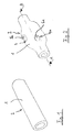
- Figure 1 shows a tube blank 1, in a first processing step in a Hydroforming (not shown) inserted and in one area 2 is widened. In the area to be expanded 2 arise in subsequent Processing steps two fork pieces, each with two fork arms.
- FIG. 2 shows the tube 1 after expansion.
- the outer contour of the tube 1 is also symmetrical in the widened area 2.
- FIG. 3 shows a section through the tube 1 of FIG. 2 along the section line A - B. From the sectional view of Fig. 3 it can be seen that the tube 1 in the Hydroforming in the holes 5 a, 5 b "retracted” is.
- the in the "collecting" arising bookings 7, 8 are for reasons of strength advantageous. Due to the indentations in the region of the holes 5a, 5b, in which later the joint bearings are used, namely results in a high "Traganteil", i. a high strength.
- the indentations 7, 8 allow a Material and thus a weight saving.
- a corresponding indentation 9 can also be seen in the area of the hole 6b.
- the holes 5a, 5b and 6a, 6b may expand upon expansion of the tube, i. immediately during hydroforming in hydroforming be punched.
- the holes 5a, 5b, 6a, 6b may also be prepared in a subsequent operation. This can e.g. by a Machining such as drilling, milling, spindling done or by Laser cutting or other suitable processing methods.
- each of the fork pieces 10, 11 each has two fork arms 12, 13 and 14, 15, in which the holes 5a, 5b or 6a, 6b are provided.
- the fork pieces before "cutting" out of the pipe - or more generally, before the cutting process - rotated by 90 ° to each other.
- the fork arms 12, 13 of the Fork 10 engage the fork arms 12, 13 of the Fork 10 in a range between the two fork arms 14, 15th the fork piece 11 is located, and vice versa. That way, the two can Fork arms 10, 11 from the expanded tube 1 almost waste-free or with only be made very low waste.
- the fork arms are "cut out” of the expanded tube 1.
- the term “cut” is extremely broad. This does not only apply Cutting method per se, such as Laser cutting, but in general Separation method, e.g. Milling.
- the fork pieces are machined by machining.
- the outer contour of the fork piece 11 are deburred and the holes 5a, 5b and 6a, 6b post-processed.
- a splined shaft 16 produced, which is a positive rotational coupling of the Fork 11 with a shaft or other component, the one corresponding external teeth has enabled.
- Figures 6-8 show the manufacture of two fork pieces, each integral are connected to a propeller shaft.
- An output pipe 1 is first through Hydroforming expanded in a range 2. Simultaneously with the Expand or in a subsequent separate step, the holes 5a, 5b and 6a, 6b produced.
- the two fork pieces 10, 11 e.g. by laser cutting from the widened region 2 of the tube 1 "Cut out".
- the fork pieces 10, 11 are not here of the respective Pipe pieces separated, but remain on pipe sections, which as Cardan shafts 18, 19 can be used.
- the fork pieces 10, 11 are so integrally connected to the respective propeller shaft 18, 19.
- end 19 of the propeller shaft 18 can then, for example, an attachment 20 are welded, which is shown in FIG. 8 is shown.
Landscapes
- Engineering & Computer Science (AREA)
- Mechanical Engineering (AREA)
- General Engineering & Computer Science (AREA)
- Physics & Mathematics (AREA)
- Fluid Mechanics (AREA)
- Forklifts And Lifting Vehicles (AREA)
- Shafts, Cranks, Connecting Bars, And Related Bearings (AREA)
Abstract
Description
- Figuren 1 - 5
- einzelne Schritte bei der Herstellung eines Gabelstücks gemäß der Erfindung; und
- Figuren 6 - 8
- einzelne Herstellschritte bei der Herstellung eines einstückig mit einer Gelenkwelle verbundenen Gabelstücks.
Claims (11)
- Verfahren zur Herstellung mindestens eines Gabelstücks (10, 11) eines Gelenkwellengelenks, wobei das Gabelstück (10, 11) zwei Gabelarme (12, 13; 14, 15) aufweist und durch folgende Bearbeitungsschritte aus einem Rohr (1) hergestellt wird:Einbringen des Rohrs (1) in einen Innenhochdruckumformwerkzeug,Aufbringen eines Innendrucks in dem Rohr (1),Aufweiten des Rohrs (1) in einem Bereich (2), in dem die Gabelarme (12, 13; 14, 15) entstehen sollen,Herstellen der Gabelarme (12, 13; 14, 15) durch Abtrennen von Rohrmaterial entlang von Außenkonturen der herzustellenden Gabelarme (12, 13; 14, 15) und Abtrennen von Rohrmaterial in einem Rohrbereich zwischen den herzustellenden Gabelarmen (12, 13; 14, 15).
- Verfahren nach Anspruch 1, wobei das Rohr (1) nach dem Aufweiten derart in zwei Teile getrennt wird, dass sich durch den Trennvorgang zwei Gabelstücke (10, 11) ergeben, die um 90° gegeneinander verdreht aus dem aufgeweiteten Rohr (1) hervorgehen, wobei vor dem Trennen der beiden Gabelstücke (10, 11) das eine Gabelstück (10) mit seinen beiden Gabelarmen (12, 13) in einen Bereich eingreift, der zwischen den beiden Gabelarmen (14, 15) des anderen Gabelstücks (11) liegt, und umgekehrt.
- Verfahren nach Anspruch 1 oder 2, wobei das Abtrennen durch Laserschneiden erfolgt.
- Verfahren nach Anspruch 1 oder 2, wobei das Abtrennen durch spanende Bearbeitung erfolgt.
- Verfahren nach Anspruch 1 oder 2, wobei das Abtrennen durch eine Fräsbearbeitung erfolgt.
- Verfahren nach einem der Ansprüche 1 bis 6, wobei in jedem der Gabelarme (12, 13; 14, 15) im Bereich des freien Endes des jeweiligen Gabelarms (12, 13; 14, 15) jeweils ein Loch (5a, 5b; 6a, 6b) zur Aufnahme eines Gelenklagers hergestellt wird, wobei die Löcher der beiden Gabelarme (12, 13; 14, 15) miteinander fluchten.
- Verfahren nach Anspruch 6, wobei die Löcher (5a, 5b; 6a, 6b) beim Innenhochdruckaufweiten des Rohrs (1) gestanzt werden.
- Verfahren nach Anspruch 6, wobei die Löcher (5a, 5b; 6a, 6b) nach dem Aufweiten des Rohrs (1) gebohrt werden.
- Verfahren nach einem der Ansprüche 1 bis 8, wobei das Gabelstück (10, 11) nach seiner Herstellung an dem Rohr (1) verbleibt und eine Gelenkwelle (18, 19) bildet.
- Verfahren nach einem der Ansprüche 1 bis 8, wobei das Gabelstück (10, 11) nach seiner Herstellung von dem Rohr (1) abgetrennt wird.
- Gabelstück (10, 11), das nach einem der in den Patentansprüchen 1 bis 10 beschriebenen Verfahren hergestellt ist.
Applications Claiming Priority (2)
| Application Number | Priority Date | Filing Date | Title |
|---|---|---|---|
| DE10345291 | 2003-09-30 | ||
| DE2003145291 DE10345291A1 (de) | 2003-09-30 | 2003-09-30 | Verfahren zur Herstellung eines Gabelstücks für ein Gelenkwellengelenk sowie ein nach diesem Verfahren hergestelltes Gabelstück |
Publications (1)
| Publication Number | Publication Date |
|---|---|
| EP1520637A1 true EP1520637A1 (de) | 2005-04-06 |
Family
ID=34306145
Family Applications (1)
| Application Number | Title | Priority Date | Filing Date |
|---|---|---|---|
| EP04020596A Withdrawn EP1520637A1 (de) | 2003-09-30 | 2004-08-31 | Verfahren zur Herstellung eines Gabelstücks für ein Gelenkwellengelenk sowie ein nach diesem Verfahren hergestelltes Gabelstück |
Country Status (2)
| Country | Link |
|---|---|
| EP (1) | EP1520637A1 (de) |
| DE (1) | DE10345291A1 (de) |
Cited By (5)
| Publication number | Priority date | Publication date | Assignee | Title |
|---|---|---|---|---|
| AT503062B1 (de) * | 2005-12-30 | 2013-06-15 | Stiwa Holding Gmbh | Verfahren zur Herstellung eines Kreuzgelenkes für eine Gelenkwelle |
| CN107520310A (zh) * | 2017-09-22 | 2017-12-29 | 太仓久信精密模具股份有限公司 | 滑动叉预成形体、滑动叉及二者的成形方法 |
| WO2019099757A1 (en) * | 2017-11-16 | 2019-05-23 | Dana Automotive Systems Group, Llc | Tube yokes and method of forming tube yokes |
| CN112091545A (zh) * | 2020-03-05 | 2020-12-18 | 上海威克迈龙川汽车发动机零件有限公司 | 一种不锈钢燃油高压油管及其制造工艺 |
| CN112496674A (zh) * | 2020-10-30 | 2021-03-16 | 无锡市腾达万向轴有限公司 | 一种万向节叉加工方法 |
Families Citing this family (1)
| Publication number | Priority date | Publication date | Assignee | Title |
|---|---|---|---|---|
| DE102007017029A1 (de) * | 2007-04-11 | 2008-10-16 | Daimler Ag | Innenhochdruckumformteil sowie Verfahren und Vorrichtung zu dessen Herstellung |
Citations (4)
| Publication number | Priority date | Publication date | Assignee | Title |
|---|---|---|---|---|
| US5673929A (en) * | 1995-03-31 | 1997-10-07 | Mascotech Tublular Products, Inc. | Process of hydroforming tubular suspension and frame components for vehicles |
| DE19713411A1 (de) * | 1997-04-01 | 1998-10-08 | Benteler Werke Ag | Verfahren zur Herstellung eines doppelwandigen Abgaskrümmers |
| US6105413A (en) * | 1994-12-29 | 2000-08-22 | Dana Corporation | Method of forming a one piece steering shaft member |
| DE10106158A1 (de) * | 2001-02-10 | 2002-10-10 | Bayerische Motoren Werke Ag | Spannvorrichtung für ein Gabelstück |
Family Cites Families (1)
| Publication number | Priority date | Publication date | Assignee | Title |
|---|---|---|---|---|
| US7080436B2 (en) * | 2001-10-18 | 2006-07-25 | Torque-Traction Technologies, Llc | Method of manufacturing an axially collapsible driveshaft |
-
2003
- 2003-09-30 DE DE2003145291 patent/DE10345291A1/de not_active Withdrawn
-
2004
- 2004-08-31 EP EP04020596A patent/EP1520637A1/de not_active Withdrawn
Patent Citations (4)
| Publication number | Priority date | Publication date | Assignee | Title |
|---|---|---|---|---|
| US6105413A (en) * | 1994-12-29 | 2000-08-22 | Dana Corporation | Method of forming a one piece steering shaft member |
| US5673929A (en) * | 1995-03-31 | 1997-10-07 | Mascotech Tublular Products, Inc. | Process of hydroforming tubular suspension and frame components for vehicles |
| DE19713411A1 (de) * | 1997-04-01 | 1998-10-08 | Benteler Werke Ag | Verfahren zur Herstellung eines doppelwandigen Abgaskrümmers |
| DE10106158A1 (de) * | 2001-02-10 | 2002-10-10 | Bayerische Motoren Werke Ag | Spannvorrichtung für ein Gabelstück |
Cited By (6)
| Publication number | Priority date | Publication date | Assignee | Title |
|---|---|---|---|---|
| AT503062B1 (de) * | 2005-12-30 | 2013-06-15 | Stiwa Holding Gmbh | Verfahren zur Herstellung eines Kreuzgelenkes für eine Gelenkwelle |
| AT13094U1 (de) * | 2005-12-30 | 2013-06-15 | Stiwa Holding Gmbh | Kreuzgelenk für eine gelenkwelle sowie verfahren zur herstellung derselben |
| CN107520310A (zh) * | 2017-09-22 | 2017-12-29 | 太仓久信精密模具股份有限公司 | 滑动叉预成形体、滑动叉及二者的成形方法 |
| WO2019099757A1 (en) * | 2017-11-16 | 2019-05-23 | Dana Automotive Systems Group, Llc | Tube yokes and method of forming tube yokes |
| CN112091545A (zh) * | 2020-03-05 | 2020-12-18 | 上海威克迈龙川汽车发动机零件有限公司 | 一种不锈钢燃油高压油管及其制造工艺 |
| CN112496674A (zh) * | 2020-10-30 | 2021-03-16 | 无锡市腾达万向轴有限公司 | 一种万向节叉加工方法 |
Also Published As
| Publication number | Publication date |
|---|---|
| DE10345291A1 (de) | 2005-04-21 |
Similar Documents
| Publication | Publication Date | Title |
|---|---|---|
| DE69531225T2 (de) | Herstellungsverfahren für eine Antriebswelle | |
| EP2467231B1 (de) | Verfahren zur herstellung eines einen abschnitt einer lenkspindel bildenden lenkspindelteils | |
| DE102013226929B4 (de) | Verfahren zur umformenden Herstellung einer Hohlwelle | |
| DE112006000619B4 (de) | Verfahren zum Herstellen einer Lenkungszahnstange | |
| EP4217619B1 (de) | Verfahren zur herstellung eines bauteiles eines gleitlagers, sowie bauteil, gleitlager und getriebe einer windkraftanlage | |
| EP1989011B1 (de) | Verfahren zur herstellung eines lenkspindelteils und lenkspindel mit einem solchen lenkspindelteil | |
| EP0328007B1 (de) | Gebaute Getriebewelle | |
| DE10020762A1 (de) | Verfahren zur Herstellung einer Hohlwelle zum Einsatz bei einer Gleitverbindung | |
| DE102004001141B4 (de) | Verfahren zur Herstellung von Wellenzapfen und zur Herstellung einer gebauten Welle | |
| DE102014104610B4 (de) | Verfahren zur Herstellung einer Schaltgabel | |
| EP1520637A1 (de) | Verfahren zur Herstellung eines Gabelstücks für ein Gelenkwellengelenk sowie ein nach diesem Verfahren hergestelltes Gabelstück | |
| DE10208116B4 (de) | Verfahren und Vorrichtung zur Bearbeitung eines Gleitlagers | |
| WO2002055232A1 (de) | Verfahren zur herstellung eines kugelgelenkgehäuses | |
| EP1000677B1 (de) | Verfahren zur Herstellung eines Bauteils mittels Innenhochdruck-Umformen | |
| DE10249768B3 (de) | Verfahren zur Herstellung eines Spurstangengehäuses | |
| EP0374389B1 (de) | Verfahren zur Vorbehandlung von Bauteilen einer gebauten Nockenwelle | |
| DE102005007143B4 (de) | Hohlwelle mit darauf durch Innenhochdruckumformen befestigten Funktionselementen und Verfahren zu deren Herstellung | |
| DE102013008658A1 (de) | Antriebselement mit einem Kegelrad für einen Kraftwagen sowie Verfahren zum Herstellen eines solchen Antriebselements | |
| DE102007025768B4 (de) | Verfahren zum Herstellen eines Bauteils aus Metall, insbesondere für ein Kopflagergehäuse eines Federbeines, sowie derartiges Bauteil | |
| EP3699442B1 (de) | Welle | |
| DE102011115954A1 (de) | Verfahren zum Herstellen einer Welle | |
| DE19901425C2 (de) | Verfahren zur Herstellung eines rohrförmigen Zahnstangenwerkstückes, insbesondere für Zahnstangenlenkungen von Kraftfahrzeugen | |
| DE102023131044B4 (de) | Verfahren zur Herstellung einer lastübertragenden Welle | |
| DE2702179A1 (de) | Profilhuelse und verfahren zu deren herstellung | |
| EP2205370B1 (de) | Verfahren und vorrichtung zur herstellung eines hohlkörpers und hohlkörper |
Legal Events
| Date | Code | Title | Description |
|---|---|---|---|
| PUAI | Public reference made under article 153(3) epc to a published international application that has entered the european phase |
Free format text: ORIGINAL CODE: 0009012 |
|
| AK | Designated contracting states |
Kind code of ref document: A1 Designated state(s): AT BE BG CH CY CZ DE DK EE ES FI FR GB GR HU IE IT LI LU MC NL PL PT RO SE SI SK TR |
|
| AX | Request for extension of the european patent |
Extension state: AL HR LT LV MK |
|
| 17P | Request for examination filed |
Effective date: 20050419 |
|
| AKX | Designation fees paid |
Designated state(s): DE FR GB IT |
|
| 17Q | First examination report despatched |
Effective date: 20070312 |
|
| STAA | Information on the status of an ep patent application or granted ep patent |
Free format text: STATUS: THE APPLICATION IS DEEMED TO BE WITHDRAWN |
|
| 18D | Application deemed to be withdrawn |
Effective date: 20070724 |