EP1520534A1 - Intrument destine a la mise en place de vis d'interference dans le domaine de la ligamentoplastie - Google Patents
Intrument destine a la mise en place de vis d'interference dans le domaine de la ligamentoplastie Download PDFInfo
- Publication number
- EP1520534A1 EP1520534A1 EP04021515A EP04021515A EP1520534A1 EP 1520534 A1 EP1520534 A1 EP 1520534A1 EP 04021515 A EP04021515 A EP 04021515A EP 04021515 A EP04021515 A EP 04021515A EP 1520534 A1 EP1520534 A1 EP 1520534A1
- Authority
- EP
- European Patent Office
- Prior art keywords
- instrument
- drilling
- screw
- tap
- instrument according
- Prior art date
- Legal status (The legal status is an assumption and is not a legal conclusion. Google has not performed a legal analysis and makes no representation as to the accuracy of the status listed.)
- Granted
Links
- 210000003041 ligament Anatomy 0.000 title claims abstract description 24
- 238000002360 preparation method Methods 0.000 title claims description 3
- 238000001356 surgical procedure Methods 0.000 title description 2
- 210000000988 bone and bone Anatomy 0.000 title 1
- 238000005553 drilling Methods 0.000 claims abstract description 19
- 239000000463 material Substances 0.000 claims description 5
- 238000000034 method Methods 0.000 description 5
- 238000009434 installation Methods 0.000 description 2
- 210000002435 tendon Anatomy 0.000 description 2
- 210000000689 upper leg Anatomy 0.000 description 2
- 230000037182 bone density Effects 0.000 description 1
- 230000001054 cortical effect Effects 0.000 description 1
- 238000002316 cosmetic surgery Methods 0.000 description 1
- 230000000694 effects Effects 0.000 description 1
- 230000000763 evoking effect Effects 0.000 description 1
- 239000004459 forage Substances 0.000 description 1
- 238000003780 insertion Methods 0.000 description 1
- 230000037431 insertion Effects 0.000 description 1
- 238000002955 isolation Methods 0.000 description 1
- 210000003127 knee Anatomy 0.000 description 1
- 238000010079 rubber tapping Methods 0.000 description 1
Images


Classifications
-
- B—PERFORMING OPERATIONS; TRANSPORTING
- B23—MACHINE TOOLS; METAL-WORKING NOT OTHERWISE PROVIDED FOR
- B23G—THREAD CUTTING; WORKING OF SCREWS, BOLT HEADS, OR NUTS, IN CONJUNCTION THEREWITH
- B23G5/00—Thread-cutting tools; Die-heads
- B23G5/02—Thread-cutting tools; Die-heads without means for adjustment
- B23G5/06—Taps
-
- A—HUMAN NECESSITIES
- A61—MEDICAL OR VETERINARY SCIENCE; HYGIENE
- A61B—DIAGNOSIS; SURGERY; IDENTIFICATION
- A61B17/00—Surgical instruments, devices or methods
- A61B17/16—Instruments for performing osteoclasis; Drills or chisels for bones; Trepans
- A61B17/1655—Instruments for performing osteoclasis; Drills or chisels for bones; Trepans for tapping
-
- A—HUMAN NECESSITIES
- A61—MEDICAL OR VETERINARY SCIENCE; HYGIENE
- A61B—DIAGNOSIS; SURGERY; IDENTIFICATION
- A61B17/00—Surgical instruments, devices or methods
- A61B17/16—Instruments for performing osteoclasis; Drills or chisels for bones; Trepans
- A61B17/17—Guides or aligning means for drills, mills, pins or wires
- A61B17/1714—Guides or aligning means for drills, mills, pins or wires for applying tendons or ligaments
-
- A—HUMAN NECESSITIES
- A61—MEDICAL OR VETERINARY SCIENCE; HYGIENE
- A61B—DIAGNOSIS; SURGERY; IDENTIFICATION
- A61B17/00—Surgical instruments, devices or methods
- A61B17/16—Instruments for performing osteoclasis; Drills or chisels for bones; Trepans
- A61B17/17—Guides or aligning means for drills, mills, pins or wires
- A61B17/1739—Guides or aligning means for drills, mills, pins or wires specially adapted for particular parts of the body
- A61B17/1764—Guides or aligning means for drills, mills, pins or wires specially adapted for particular parts of the body for the knee
Definitions
- the present invention relates to an instrument intended for the installation of interference screws in the field of ligamentoplasty.
- Such an instrument is indispensable for fixing technique applicable for the reconstruction of intra-articular ligaments but can also be used for fixing and reconstruction of tendons and extra-articular ligaments.
- the interference screws being made of material resorbable or not, more or less fragile, it exists taps adapted to the thread of the screw for to facilitate the insertion of this one.
- the establishment of the interference screw in the tunnel formed by a femoral blind hole or in a tibial blind hole is delicate.
- the difficulty lies mainly in the fact that when screwing the interference screw, this causes a rotation by drive of the ligament or tendon in the tunnel that is uneven, in function of the diameters of all components in presence and the operated side (right femur or femur left).
- the expected accuracy in this type of operation is of the order of half millimeter or millimeter, but that in case of graft rotation the positioning error can to be around 3 to 5 mm.
- the instrument consists of a tap that has to prepare the future path of the screw interference in order to decrease the torque of rubbing, but by no means this known tap prevents the phenomena of slippage grafts, causing their rotation, as evoked above.
- the present invention aims to remedy to the various disadvantages known in the art previous and above mentioned.
- an instrument intended for the installation of interference screws in the field of intra-articular ligamentoplasty or extra-articular characterized in what the lateral part of its part auger apt preparing the location of the screw interference, has on at least one of its generators, a longitudinal recess open towards outside, forming a guide for drilling in the articulation of a tunnel substantially hemicylindrical whose position for a secant drilling with the location with the screw is determined by the time position of said instrument, so as to prepare in a first step the location of the interference screw and in a second time, by drilling secant the tunnel intended to receive a ligament or graft, so to avoid the rotation of the latter by drive, when screwing the screw interference, while allowing the immobilisation in place of said ligament by the screw.
- Such an instrument according to the invention allows to avoid, that at the time of the screwing proper the interference screw, this one can lead to in its thread the ligament (s) or graft (s).
- the present invention also relates to characteristics that will emerge during the description which will follow, and which will have to be considered in isolation or in all their possible technical combinations.
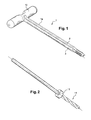
- the instrument 1 designated globally on the figures, object of the invention, is characterized in that that the lateral part la of its part auger apt preparing the location of the screw 7, has on at least one of its generators, a longitudinal recess 2, 3 open towards the outside, forming a guide intended piercing in the articulation 4 of a tunnel 5; 6 substantially hemicylindrical whose position in view of a secant piercing with the location with the screw 7 is determined by the time position of said instrument 1, so as to prepare in a first time the location of the interference screw 7 and in a second step, by piercing secant the tunnel 5, 6 for receiving a ligament or graft 8, 9, to avoid the rotation of this last training, when screwing the screw of interference 7, while allowing the immobilization in place of said ligament 8, 9 by the screw 7.
- instrument 1 has two of its generators diametrically opposed, two longitudinal recesses 2, 3 open towards outside, forming guides for drilling two substantially hemicylindrical tunnels 5, 6, their relative position being determined by a first time position of the instrument 1 when a first hole and a second position time of the same instrument 1 during a second piercing, so as to determine the location and the realization of said tunnels 5, 6 for the purpose of subsequent placement of two ligaments 8, 9, according to selected locations and their immobilization with a single screw interference 7.
- the distance from its tunnels is defined by the time position of the instrument during drilling.
- the instrument 1 is constituted by a tap, surmounted by a removable handle 10 in which opens the recesses 2, 3 in the form of two holes 2a, 3a of the diameter of the tunnels 5, 6 to realize later in the articulation 4, a such a handle 10 allowing both the rotational actuation of the tap 1 according to a predetermined depth and commitment of a tool 11 in each of the holes 2a, 3a in order to to make said tunnels 5, 6 according to angularly spaced locations, also of predetermined manner.
- the holes 2a, 3a are made in the handle 10 of the tap 1 to equal distance from the center of it, hence the interference screw 7 to put in place later.
- the diameters of the holes 2a, 3a made in the handle 10 of the tap 1 and the diameter of Hemicylindrical recesses 2, 3 which prolong them are of values adapted to the case to be treated and possibly different.
- the tap may be of diameter and of variable length, depending on the case treat.
- tunnel drilling hemi-cylindrical 5, 6 is achieved using a drilling tool 11, wick or dilator, comprising a stop end of drilling 12 and / or a graduation.
- the interference screw 7 is made in a resorbable or non-absorbable material.
- the upper part of the handle also include indications 12 indicating for example a round of tap corresponds to a 2.5mm depression.
- the longitudinal recesses 2, 3 and the holes above them 2a, 3a are drilled in the tap body for the purpose of ergonomics optimized.
- Tap 1 as described above may have variable diameters with holes for grafts of different diameters.
- a 7mm diameter tap will be equipped with two holes intended for housing grafts of diameters 4mm - 5mm.
Landscapes
- Health & Medical Sciences (AREA)
- Life Sciences & Earth Sciences (AREA)
- Surgery (AREA)
- Orthopedic Medicine & Surgery (AREA)
- Engineering & Computer Science (AREA)
- Heart & Thoracic Surgery (AREA)
- Molecular Biology (AREA)
- Oral & Maxillofacial Surgery (AREA)
- Dentistry (AREA)
- Biomedical Technology (AREA)
- Veterinary Medicine (AREA)
- Medical Informatics (AREA)
- Nuclear Medicine, Radiotherapy & Molecular Imaging (AREA)
- Animal Behavior & Ethology (AREA)
- General Health & Medical Sciences (AREA)
- Public Health (AREA)
- Mechanical Engineering (AREA)
- Rheumatology (AREA)
- Surgical Instruments (AREA)
- Prostheses (AREA)
Abstract
Description
- de visser le taraud 1 dans un trou borgne préalablement réalisé dans l'articulation 4, en creusant le filet de la vis d'interférence 7,
- une fois le taraud 1 introduit dans le condyle, il est possible d'engager un outil de forage pouvant être en butée ou graduée, afin de préparer les tunnels 5, 6 des ligaments 8, 9 correspondants aux faisceaux fémoraux.
Claims (9)
- Instrument (1) destiné à la mise en place de vis d'interférence (7) dans le domaine de la ligamentoplastie intra-articulaires ou extra-articulaires, caractérisé en ce que la partie latérale (la) de sa partie foreuse apte à la préparation de l'emplacement de la vis d'interférence (7), comporte sur au moins l'une de ses génératrices, un évidement longitudinal (2, 3) ouvert vers l'extérieur, formant un guide destiné au perçage dans l'articulation (4) d'un tunnel (5, 6) sensiblement hémicylindrique dont la position en vue d'un perçage sécant avec l'emplacement avec la vis (7) est déterminé par la position horaire dudit instrument (1), de manière à préparer dans un premier temps l'emplacement de la vis d'interférence (7) et dans un deuxième temps, par perçage sécant le tunnel (5, 6) destiné à recevoir un ligament ou greffon (8, 9), afin d'éviter la rotation de ce dernier par entraínement, lors du vissage de la vis d'interférence (7), tout en autorisant l'immobilisation en place dudit ligament (8, 9) par la vis (7).
- Instrument selon la revendication 1, caractérisé en ce qu'il comporte sur deux de ses génératrices diamétralement opposées, deux évidements longitudinaux (2, 3) ouverts vers l'extérieur, formant des guides destinés au perçage de deux tunnels (5, 6) sensiblement hémicylindriques, leur position relative étant déterminée par une première position horaire de l'instrument (1) lors d'un premier perçage et par une deuxième position horaire du même instrument (1) lors d'un second perçage, de manière à déterminer l'emplacement et la réalisation desdits tunnels (5, 6) en vue de la mise en place ultérieure de deux ligaments (8, 9), selon des emplacements choisis et de leur immobilisation à l'aide d'une seule vis d'interférence (7).
- Instrument selon l'une des revendications 1 ou 2, caractérisé en ce qu'il constitué par un taraud (1) surmonté par une poignée amovible (10) dans laquelle débouche les évidements (2, 3) sous forme de deux trous (2a, 3a) du diamètre des tunnels (5, 6) à réaliser ultérieurement dans l'articulation (4), une telle poignée (10) permettant à la fois l'actionnement en rotation du taraud (1) selon une profondeur prédéterminée et l'engagement d'un outil de forage (11) dans chacun des trous (2a, 3a) afin de réaliser lesdits tunnels (5, 6) selon des emplacements espacés angulairement, également de manière prédéterminée.
- Instrument selon la revendication 3, caractérisé en ce que les trous (2a, 3a) sont réalisés dans la poignée (10) du taraud (1) à égale distance du centre de celui-ci, d'où de la vis d'interférence (7) à mettre en place ultérieurement.
- Instrument selon l'une des revendications 3 ou 4, caractérisé en ce que le diamètre des trous (2a, 3a) réalisés dans la poignée (10) du taraud (1) et le diamètre des évidements hémicylindrique (2, 3) qui les prolongent sont de valeurs adaptées au cas à traiter et éventuellement différentes.
- Instrument selon l'une des revendications 1 à 5, caractérisé en ce que le taraud (1) qui le constitue est de diamètre et de longueur variables en fonction du cas à traiter.
- Instrument selon l'une des revendications 1 à 6, caractérisé en ce que le perçage du tunnel hémicylindrique (5, 6) est réalisé à l'aide d'un outil de forage (11), mèche ou dilatateur, comportant une butée de fin de forage (12) et/ou une graduation.
- Instrument selon l'une des revendications 1 à 7, caractérisé en ce que la vis d'interférence (7) est réalisée en un matériau résorbable.
- Instrument selon l'une des revendications 1 à 7, caractérisé en ce que la vis d'interférence (7) est réalisée en un matériau non résorbable.
Applications Claiming Priority (2)
| Application Number | Priority Date | Filing Date | Title |
|---|---|---|---|
| FR0311643A FR2860418B1 (fr) | 2003-10-02 | 2003-10-02 | Instrument destine a la mise en place de vis d'interference dans le domaine de la ligamentoplastie |
| FR0311643 | 2003-10-02 |
Publications (2)
| Publication Number | Publication Date |
|---|---|
| EP1520534A1 true EP1520534A1 (fr) | 2005-04-06 |
| EP1520534B1 EP1520534B1 (fr) | 2006-09-06 |
Family
ID=34307426
Family Applications (1)
| Application Number | Title | Priority Date | Filing Date |
|---|---|---|---|
| EP04021515A Expired - Lifetime EP1520534B1 (fr) | 2003-10-02 | 2004-09-10 | Intrument destine a la mise en place de vis d'interference dans le domaine de la ligamentoplastie |
Country Status (5)
| Country | Link |
|---|---|
| EP (1) | EP1520534B1 (fr) |
| AT (1) | ATE338515T1 (fr) |
| DE (1) | DE602004002255T2 (fr) |
| ES (1) | ES2273137T3 (fr) |
| FR (1) | FR2860418B1 (fr) |
Cited By (3)
| Publication number | Priority date | Publication date | Assignee | Title |
|---|---|---|---|---|
| FR2938745A1 (fr) * | 2008-09-12 | 2010-05-28 | Tettra Marketing Llp | Taraud pour la mise en place d'une cage d'un dispositif de fixation pour ligamentoplastie |
| CN103006312A (zh) * | 2010-09-03 | 2013-04-03 | 张强 | 微创骨折螺钉置入开口器 |
| CN103315804A (zh) * | 2013-06-09 | 2013-09-25 | 无锡市华牧机械有限公司 | 一种骨科专用丝锥 |
Families Citing this family (1)
| Publication number | Priority date | Publication date | Assignee | Title |
|---|---|---|---|---|
| GB2443795B (en) * | 2006-10-06 | 2011-04-13 | Dalmatic As | Leads for use in orthopaedic surgery |
Citations (4)
| Publication number | Priority date | Publication date | Assignee | Title |
|---|---|---|---|---|
| US5234430A (en) * | 1991-12-18 | 1993-08-10 | Huebner Randall J | Orthopedic fixation screw and method |
| FR2735008A1 (fr) * | 1995-06-07 | 1996-12-13 | Jbs Sa | Ensemble pour preparation d'arthrodese intervertebrale |
| US5643269A (en) * | 1990-08-24 | 1997-07-01 | Haerle; Anton | Externally threaded bodies for use as taps or screws |
| US20030018337A1 (en) * | 2001-07-17 | 2003-01-23 | Davis Reginald J. | Bone drill and tap combination |
-
2003
- 2003-10-02 FR FR0311643A patent/FR2860418B1/fr not_active Expired - Fee Related
-
2004
- 2004-09-10 ES ES04021515T patent/ES2273137T3/es not_active Expired - Lifetime
- 2004-09-10 AT AT04021515T patent/ATE338515T1/de not_active IP Right Cessation
- 2004-09-10 EP EP04021515A patent/EP1520534B1/fr not_active Expired - Lifetime
- 2004-09-10 DE DE602004002255T patent/DE602004002255T2/de not_active Expired - Lifetime
Patent Citations (4)
| Publication number | Priority date | Publication date | Assignee | Title |
|---|---|---|---|---|
| US5643269A (en) * | 1990-08-24 | 1997-07-01 | Haerle; Anton | Externally threaded bodies for use as taps or screws |
| US5234430A (en) * | 1991-12-18 | 1993-08-10 | Huebner Randall J | Orthopedic fixation screw and method |
| FR2735008A1 (fr) * | 1995-06-07 | 1996-12-13 | Jbs Sa | Ensemble pour preparation d'arthrodese intervertebrale |
| US20030018337A1 (en) * | 2001-07-17 | 2003-01-23 | Davis Reginald J. | Bone drill and tap combination |
Cited By (3)
| Publication number | Priority date | Publication date | Assignee | Title |
|---|---|---|---|---|
| FR2938745A1 (fr) * | 2008-09-12 | 2010-05-28 | Tettra Marketing Llp | Taraud pour la mise en place d'une cage d'un dispositif de fixation pour ligamentoplastie |
| CN103006312A (zh) * | 2010-09-03 | 2013-04-03 | 张强 | 微创骨折螺钉置入开口器 |
| CN103315804A (zh) * | 2013-06-09 | 2013-09-25 | 无锡市华牧机械有限公司 | 一种骨科专用丝锥 |
Also Published As
| Publication number | Publication date |
|---|---|
| ATE338515T1 (de) | 2006-09-15 |
| FR2860418A1 (fr) | 2005-04-08 |
| FR2860418B1 (fr) | 2005-12-16 |
| DE602004002255T2 (de) | 2007-04-05 |
| EP1520534B1 (fr) | 2006-09-06 |
| ES2273137T3 (es) | 2007-05-01 |
| DE602004002255D1 (de) | 2006-10-19 |
Similar Documents
| Publication | Publication Date | Title |
|---|---|---|
| EP1074230B1 (fr) | Implant malléolaire pour prothèse partielle ou totale de cheville et matériel ancillaire de pose d'un tel implant | |
| EP0856293B1 (fr) | Dispositif de vis à tête filetée destiné à pernettre la fixation de petits fragments d'os | |
| EP0599752B1 (fr) | Dispositif d'ostéosynthèse pour fractures trochantérienne ou trochantéro-diaphysaire | |
| EP0983755B1 (fr) | Implant pour pied plat | |
| FR2649604A1 (fr) | Instrument ancillaire chirurgical de reperage de l'entree et de la direction du tunnel d'insertion femorale d'un neo-ligament dans des conditions d'isometrie totale | |
| EP0814730A1 (fr) | Ancre chirurgicale pour ligaments | |
| EP2398404B1 (fr) | Dispositif pour faciliter la mise en place de vis dans les tissus osseux et instrumentation en faisant application, en particulier pour realiser l'osteosynthese de fragments d'os | |
| FR2699065A1 (fr) | Vis autocompressive pour le traitement des fractures épiphysaires et/ou ostéo-chondrales. | |
| FR2572648A1 (fr) | Dispositif a vis de serrage de hanche pour reduction de fracture du femur | |
| CH627935A5 (fr) | Ensemble de pieces pour la mise en oeuvre d'un procede d'osteosynthese. | |
| FR2750031A1 (fr) | Dispositif d'ancrage osseux pour fil de suture et instrument permettant la mise en place de ce dispositif | |
| FR2459650A1 (fr) | Dispositif intramedullaire de compression pour fracture des os | |
| CA2460427A1 (fr) | Dispositif de mise en place d'un biomateriau | |
| FR2560764A1 (fr) | Davier pour la reduction de fracture | |
| EP1520534B1 (fr) | Intrument destine a la mise en place de vis d'interference dans le domaine de la ligamentoplastie | |
| FR2879915A1 (fr) | Vis d'interference et tournevis adapte | |
| CA2283683A1 (fr) | Implant pour dispositif d'osteosynthese et outil de montage d'un tel implant | |
| FR2804598A1 (fr) | Dispositif de fixation d'un implant ou d'un transplant formant ligament prothetique sur un os | |
| FR2683716A1 (fr) | Greffon renforce pour ligamentoplastie du genou. | |
| EP4719267A1 (fr) | Système de fixation et kit de fixation pour ligamentoplastie | |
| EP3222378A1 (fr) | Coupe-tubes avec calibreur et alésoir/ébavureur des bords du tube coupé | |
| FR2924596A1 (fr) | Dispositif de fixation pour ligamentoplastie. | |
| FR2787699A1 (fr) | Dispositif d'aide au percage d'avant-trous dans au moins un os pour la pose d'une agrafe | |
| WO1994000079A1 (fr) | Instrumentation ancillaire pour la ligamentoplastie coraco-claviculaire | |
| WO2011010065A1 (fr) | Instrumentation et méthode chirurgicale de préparation du fémur pour la mise en place d'un transplant double faisceau destiné à reconstruire un ligament croisé antérieur |
Legal Events
| Date | Code | Title | Description |
|---|---|---|---|
| PUAI | Public reference made under article 153(3) epc to a published international application that has entered the european phase |
Free format text: ORIGINAL CODE: 0009012 |
|
| AK | Designated contracting states |
Kind code of ref document: A1 Designated state(s): AT BE BG CH CY CZ DE DK EE ES FI FR GB GR HU IE IT LI LU MC NL PL PT RO SE SI SK TR |
|
| AX | Request for extension of the european patent |
Extension state: AL HR LT LV MK |
|
| 17P | Request for examination filed |
Effective date: 20050608 |
|
| AKX | Designation fees paid |
Designated state(s): AT BE BG CH CY CZ DE DK EE ES FI FR GB GR HU IE IT LI LU MC NL PL PT RO SE SI SK TR |
|
| GRAP | Despatch of communication of intention to grant a patent |
Free format text: ORIGINAL CODE: EPIDOSNIGR1 |
|
| GRAS | Grant fee paid |
Free format text: ORIGINAL CODE: EPIDOSNIGR3 |
|
| GRAA | (expected) grant |
Free format text: ORIGINAL CODE: 0009210 |
|
| AK | Designated contracting states |
Kind code of ref document: B1 Designated state(s): AT BE BG CH CY CZ DE DK EE ES FI FR GB GR HU IE IT LI LU MC NL PL PT RO SE SI SK TR |
|
| PG25 | Lapsed in a contracting state [announced via postgrant information from national office to epo] |
Ref country code: FI Free format text: LAPSE BECAUSE OF FAILURE TO SUBMIT A TRANSLATION OF THE DESCRIPTION OR TO PAY THE FEE WITHIN THE PRESCRIBED TIME-LIMIT Effective date: 20060906 Ref country code: PL Free format text: LAPSE BECAUSE OF FAILURE TO SUBMIT A TRANSLATION OF THE DESCRIPTION OR TO PAY THE FEE WITHIN THE PRESCRIBED TIME-LIMIT Effective date: 20060906 Ref country code: IE Free format text: LAPSE BECAUSE OF FAILURE TO SUBMIT A TRANSLATION OF THE DESCRIPTION OR TO PAY THE FEE WITHIN THE PRESCRIBED TIME-LIMIT Effective date: 20060906 Ref country code: SK Free format text: LAPSE BECAUSE OF FAILURE TO SUBMIT A TRANSLATION OF THE DESCRIPTION OR TO PAY THE FEE WITHIN THE PRESCRIBED TIME-LIMIT Effective date: 20060906 Ref country code: SI Free format text: LAPSE BECAUSE OF FAILURE TO SUBMIT A TRANSLATION OF THE DESCRIPTION OR TO PAY THE FEE WITHIN THE PRESCRIBED TIME-LIMIT Effective date: 20060906 Ref country code: CZ Free format text: LAPSE BECAUSE OF FAILURE TO SUBMIT A TRANSLATION OF THE DESCRIPTION OR TO PAY THE FEE WITHIN THE PRESCRIBED TIME-LIMIT Effective date: 20060906 Ref country code: RO Free format text: LAPSE BECAUSE OF FAILURE TO SUBMIT A TRANSLATION OF THE DESCRIPTION OR TO PAY THE FEE WITHIN THE PRESCRIBED TIME-LIMIT Effective date: 20060906 Ref country code: AT Free format text: LAPSE BECAUSE OF FAILURE TO SUBMIT A TRANSLATION OF THE DESCRIPTION OR TO PAY THE FEE WITHIN THE PRESCRIBED TIME-LIMIT Effective date: 20060906 |
|
| REG | Reference to a national code |
Ref country code: GB Ref legal event code: FG4D Free format text: NOT ENGLISH |
|
| REG | Reference to a national code |
Ref country code: CH Ref legal event code: EP |
|
| PG25 | Lapsed in a contracting state [announced via postgrant information from national office to epo] |
Ref country code: MC Free format text: LAPSE BECAUSE OF NON-PAYMENT OF DUE FEES Effective date: 20060930 |
|
| REG | Reference to a national code |
Ref country code: IE Ref legal event code: FG4D Free format text: LANGUAGE OF EP DOCUMENT: FRENCH |
|
| REF | Corresponds to: |
Ref document number: 602004002255 Country of ref document: DE Date of ref document: 20061019 Kind code of ref document: P |
|
| PG25 | Lapsed in a contracting state [announced via postgrant information from national office to epo] |
Ref country code: SE Free format text: LAPSE BECAUSE OF FAILURE TO SUBMIT A TRANSLATION OF THE DESCRIPTION OR TO PAY THE FEE WITHIN THE PRESCRIBED TIME-LIMIT Effective date: 20061206 Ref country code: BG Free format text: LAPSE BECAUSE OF FAILURE TO SUBMIT A TRANSLATION OF THE DESCRIPTION OR TO PAY THE FEE WITHIN THE PRESCRIBED TIME-LIMIT Effective date: 20061206 Ref country code: DK Free format text: LAPSE BECAUSE OF FAILURE TO SUBMIT A TRANSLATION OF THE DESCRIPTION OR TO PAY THE FEE WITHIN THE PRESCRIBED TIME-LIMIT Effective date: 20061206 |
|
| GBT | Gb: translation of ep patent filed (gb section 77(6)(a)/1977) |
Effective date: 20061120 |
|
| REG | Reference to a national code |
Ref country code: CH Ref legal event code: NV Representative=s name: WILLIAM BLANC & CIE CONSEILS EN PROPRIETE INDUSTRI |
|
| PG25 | Lapsed in a contracting state [announced via postgrant information from national office to epo] |
Ref country code: PT Free format text: LAPSE BECAUSE OF FAILURE TO SUBMIT A TRANSLATION OF THE DESCRIPTION OR TO PAY THE FEE WITHIN THE PRESCRIBED TIME-LIMIT Effective date: 20070219 |
|
| REG | Reference to a national code |
Ref country code: IE Ref legal event code: FD4D |
|
| REG | Reference to a national code |
Ref country code: ES Ref legal event code: FG2A Ref document number: 2273137 Country of ref document: ES Kind code of ref document: T3 |
|
| PLBE | No opposition filed within time limit |
Free format text: ORIGINAL CODE: 0009261 |
|
| STAA | Information on the status of an ep patent application or granted ep patent |
Free format text: STATUS: NO OPPOSITION FILED WITHIN TIME LIMIT |
|
| 26N | No opposition filed |
Effective date: 20070607 |
|
| PG25 | Lapsed in a contracting state [announced via postgrant information from national office to epo] |
Ref country code: GR Free format text: LAPSE BECAUSE OF FAILURE TO SUBMIT A TRANSLATION OF THE DESCRIPTION OR TO PAY THE FEE WITHIN THE PRESCRIBED TIME-LIMIT Effective date: 20061207 |
|
| PG25 | Lapsed in a contracting state [announced via postgrant information from national office to epo] |
Ref country code: EE Free format text: LAPSE BECAUSE OF FAILURE TO SUBMIT A TRANSLATION OF THE DESCRIPTION OR TO PAY THE FEE WITHIN THE PRESCRIBED TIME-LIMIT Effective date: 20060906 |
|
| PG25 | Lapsed in a contracting state [announced via postgrant information from national office to epo] |
Ref country code: HU Free format text: LAPSE BECAUSE OF FAILURE TO SUBMIT A TRANSLATION OF THE DESCRIPTION OR TO PAY THE FEE WITHIN THE PRESCRIBED TIME-LIMIT Effective date: 20070307 Ref country code: LU Free format text: LAPSE BECAUSE OF NON-PAYMENT OF DUE FEES Effective date: 20060910 Ref country code: TR Free format text: LAPSE BECAUSE OF FAILURE TO SUBMIT A TRANSLATION OF THE DESCRIPTION OR TO PAY THE FEE WITHIN THE PRESCRIBED TIME-LIMIT Effective date: 20060906 |
|
| REG | Reference to a national code |
Ref country code: CH Ref legal event code: PFA Owner name: DESARNAUD, MICHEL Free format text: CENTERPULSE FRANCE SA#127, RUE RENE JACOT, TECHNOLAND#25460 ETUPES CEDEX (FR) $ DESARNAUD, MICHEL#7, RUE BEGUE-DAVID#31400 TOULOUSE (FR) -TRANSFER TO- DESARNAUD, MICHEL#7, RUE BEGUE-DAVID#31400 TOULOUSE (FR) $ ZIMMER FRANCE SAS#127, AVENUE RENE JACOT BP 34#25461 ETUPES CEDEX (FR) |
|
| PG25 | Lapsed in a contracting state [announced via postgrant information from national office to epo] |
Ref country code: CY Free format text: LAPSE BECAUSE OF FAILURE TO SUBMIT A TRANSLATION OF THE DESCRIPTION OR TO PAY THE FEE WITHIN THE PRESCRIBED TIME-LIMIT Effective date: 20060906 |
|
| NLT1 | Nl: modifications of names registered in virtue of documents presented to the patent office pursuant to art. 16 a, paragraph 1 |
Owner name: MICHEL DESARNAUD Owner name: ZIMMER FRANCE |
|
| REG | Reference to a national code |
Ref country code: FR Ref legal event code: CJ Ref country code: FR Ref legal event code: CD |
|
| REG | Reference to a national code |
Ref country code: CH Ref legal event code: PFA Owner name: DESARNAUD, MICHEL Free format text: DESARNAUD, MICHEL#7, RUE BEGUE-DAVID#31400 TOULOUSE (FR) $ ZIMMER FRANCE SAS#127, AVENUE RENE JACOT BP 34#25461 ETUPES CEDEX (FR) -TRANSFER TO- DESARNAUD, MICHEL#7, RUE BEGUE-DAVID#31400 TOULOUSE (FR) $ ZIMMER FRANCE SAS#127, AVENUE RENE JACOT BP 34#25461 ETUPES CEDEX (FR) |
|
| REG | Reference to a national code |
Ref country code: CH Ref legal event code: PCAR Free format text: NOVAGRAAF SWITZERLAND SA;CHEMIN DE L'ECHO 3;1213 ONEX (CH) |
|
| REG | Reference to a national code |
Ref country code: FR Ref legal event code: PLFP Year of fee payment: 12 |
|
| REG | Reference to a national code |
Ref country code: FR Ref legal event code: PLFP Year of fee payment: 13 |
|
| REG | Reference to a national code |
Ref country code: FR Ref legal event code: PLFP Year of fee payment: 14 |
|
| PGFP | Annual fee paid to national office [announced via postgrant information from national office to epo] |
Ref country code: BE Payment date: 20170724 Year of fee payment: 14 Ref country code: NL Payment date: 20170919 Year of fee payment: 14 |
|
| PGFP | Annual fee paid to national office [announced via postgrant information from national office to epo] |
Ref country code: ES Payment date: 20171002 Year of fee payment: 14 |
|
| REG | Reference to a national code |
Ref country code: FR Ref legal event code: PLFP Year of fee payment: 15 |
|
| REG | Reference to a national code |
Ref country code: NL Ref legal event code: MM Effective date: 20181001 |
|
| REG | Reference to a national code |
Ref country code: BE Ref legal event code: MM Effective date: 20180930 |
|
| PG25 | Lapsed in a contracting state [announced via postgrant information from national office to epo] |
Ref country code: NL Free format text: LAPSE BECAUSE OF NON-PAYMENT OF DUE FEES Effective date: 20181001 |
|
| PG25 | Lapsed in a contracting state [announced via postgrant information from national office to epo] |
Ref country code: BE Free format text: LAPSE BECAUSE OF NON-PAYMENT OF DUE FEES Effective date: 20180930 |
|
| REG | Reference to a national code |
Ref country code: ES Ref legal event code: FD2A Effective date: 20191030 |
|
| PGFP | Annual fee paid to national office [announced via postgrant information from national office to epo] |
Ref country code: IT Payment date: 20190712 Year of fee payment: 16 Ref country code: FR Payment date: 20190809 Year of fee payment: 16 |
|
| PG25 | Lapsed in a contracting state [announced via postgrant information from national office to epo] |
Ref country code: ES Free format text: LAPSE BECAUSE OF NON-PAYMENT OF DUE FEES Effective date: 20180911 |
|
| PG25 | Lapsed in a contracting state [announced via postgrant information from national office to epo] |
Ref country code: FR Free format text: LAPSE BECAUSE OF NON-PAYMENT OF DUE FEES Effective date: 20200930 |
|
| PGFP | Annual fee paid to national office [announced via postgrant information from national office to epo] |
Ref country code: GB Payment date: 20210810 Year of fee payment: 18 Ref country code: DE Payment date: 20210813 Year of fee payment: 18 Ref country code: CH Payment date: 20210816 Year of fee payment: 18 |
|
| PG25 | Lapsed in a contracting state [announced via postgrant information from national office to epo] |
Ref country code: IT Free format text: LAPSE BECAUSE OF NON-PAYMENT OF DUE FEES Effective date: 20200910 |
|
| REG | Reference to a national code |
Ref country code: DE Ref legal event code: R119 Ref document number: 602004002255 Country of ref document: DE |
|
| REG | Reference to a national code |
Ref country code: CH Ref legal event code: PL |
|
| GBPC | Gb: european patent ceased through non-payment of renewal fee |
Effective date: 20220910 |
|
| PG25 | Lapsed in a contracting state [announced via postgrant information from national office to epo] |
Ref country code: LI Free format text: LAPSE BECAUSE OF NON-PAYMENT OF DUE FEES Effective date: 20220930 Ref country code: DE Free format text: LAPSE BECAUSE OF NON-PAYMENT OF DUE FEES Effective date: 20230401 Ref country code: CH Free format text: LAPSE BECAUSE OF NON-PAYMENT OF DUE FEES Effective date: 20220930 |
|
| PG25 | Lapsed in a contracting state [announced via postgrant information from national office to epo] |
Ref country code: GB Free format text: LAPSE BECAUSE OF NON-PAYMENT OF DUE FEES Effective date: 20220910 |