EP1520477B1 - Stuffing device for stuffed food products - Google Patents
Stuffing device for stuffed food products Download PDFInfo
- Publication number
- EP1520477B1 EP1520477B1 EP20030405863 EP03405863A EP1520477B1 EP 1520477 B1 EP1520477 B1 EP 1520477B1 EP 20030405863 EP20030405863 EP 20030405863 EP 03405863 A EP03405863 A EP 03405863A EP 1520477 B1 EP1520477 B1 EP 1520477B1
- Authority
- EP
- European Patent Office
- Prior art keywords
- piston
- filling
- movement
- cylinder
- outlet
- Prior art date
- Legal status (The legal status is an assumption and is not a legal conclusion. Google has not performed a legal analysis and makes no representation as to the accuracy of the status listed.)
- Expired - Lifetime
Links
- 235000013305 food Nutrition 0.000 title claims description 21
- 230000033001 locomotion Effects 0.000 claims description 87
- 239000000126 substance Substances 0.000 claims 4
- 238000007599 discharging Methods 0.000 claims 2
- 235000015173 baked goods and baking mixes Nutrition 0.000 description 7
- 238000006073 displacement reaction Methods 0.000 description 5
- 238000004519 manufacturing process Methods 0.000 description 5
- 230000005540 biological transmission Effects 0.000 description 3
- 230000005484 gravity Effects 0.000 description 2
- 239000007788 liquid Substances 0.000 description 2
- 230000001105 regulatory effect Effects 0.000 description 2
- 235000002595 Solanum tuberosum Nutrition 0.000 description 1
- 244000061456 Solanum tuberosum Species 0.000 description 1
- 230000000903 blocking effect Effects 0.000 description 1
- 238000005352 clarification Methods 0.000 description 1
- 210000001520 comb Anatomy 0.000 description 1
- 239000006071 cream Substances 0.000 description 1
- 230000002950 deficient Effects 0.000 description 1
- 230000000694 effects Effects 0.000 description 1
- 235000013601 eggs Nutrition 0.000 description 1
- 235000019197 fats Nutrition 0.000 description 1
- 239000000945 filler Substances 0.000 description 1
- 235000013312 flour Nutrition 0.000 description 1
- 238000004898 kneading Methods 0.000 description 1
- 235000013372 meat Nutrition 0.000 description 1
- 239000000203 mixture Substances 0.000 description 1
- 230000003287 optical effect Effects 0.000 description 1
- 235000012015 potatoes Nutrition 0.000 description 1
- 230000002028 premature Effects 0.000 description 1
- 239000007787 solid Substances 0.000 description 1
- 235000013311 vegetables Nutrition 0.000 description 1
Images
Classifications
-
- A—HUMAN NECESSITIES
- A21—BAKING; EDIBLE DOUGHS
- A21C—MACHINES OR EQUIPMENT FOR MAKING OR PROCESSING DOUGHS; HANDLING BAKED ARTICLES MADE FROM DOUGH
- A21C9/00—Other apparatus for handling dough or dough pieces
- A21C9/06—Apparatus for filling pieces of dough such as doughnuts
Landscapes
- Life Sciences & Earth Sciences (AREA)
- Engineering & Computer Science (AREA)
- Food Science & Technology (AREA)
- Manufacturing And Processing Devices For Dough (AREA)
- Confectionery (AREA)
Description
Die Erfindung betrifft eine Vorrichtung mit zumindest einem Ausgang zum Aufbringen einer Füllung auf eine teigartige Lebensmittelmasse, insbesondere einen Teig, sowie je einem Ausstosszylinder und einem Ausstosselement für den zumindest einen Ausgang, wobei die Füllung mit dem Ausstosselement aus dem Ausstosszylinder ausstoss- und durch den zumindest einen Ausgang auf die Lebensmittelmasse aufbringbar ist.The invention relates to a device having at least one output for applying a filling to a dough-like food mass, in particular a dough, and each an ejection cylinder and an ejection element for the at least one output, wherein the filling expelled with the ejection element from the ejection cylinder and by the at least an output on the food mass can be applied.
Gefüllte Lebensmittel, insbesondere gefüllte Backwaren erfreuen sich grosser Beliebtheit. Zum Füllen solcher Lebensmittel gibt es verschiedene Systeme. Bekannt sind beispielsweise Kolbensysteme, bei welchen die Füllung in einen Zylinder befördert und mit einem Kolben aus dem Zylinder ausgestossen und dabei auf ein Teigstück auf-oder darin eingebracht wird. Ein derartiges System ist beispielsweise in der FR 2 716 078 beschrieben. Dieses System umfasst einen Trichter (6) zum Einfüllen der Füllung. Am unteren Ende des Trichters befindet sich ein Kanal (5), durch welchen hindurch die Füllung in eine Kammer (3) gelangt. Diese Kammer ist auf einer Seite mit einer Öffnung versehen, durch welche die Füllung mit einem Kolben (7) heraus gepresst wird.Stuffed foods, in particular filled baked goods are very popular. There are various systems for filling such foods. Piston systems, for example, are known in which the filling is conveyed into a cylinder and ejected out of the cylinder with a piston and thereby introduced onto or into a dough piece. Such a system is described, for example, in
Bei einem anderen System zum Füllen solcher Backwaren wird die Füllung mit Hilfe einer sogenannten Schnecke aus dem Zylinder ausgestossen. Solche Systeme sind ähnlich aufgebaut wie Kolbensysteme. Anstatt eines Kolbens, der eine Hin- und Herbewegung ausführt und auf diese Weise die Füllung aus dem Zylinder ausstösst, ist in dem Zylinder jedoch eine Schneckenschraube vorgesehen, welche mittels einer Rotationsbewegung die Füllung aus dem Zylinder ausstösst.In another system for filling such baked goods, the filling is expelled from the cylinder with the aid of a so-called screw. Such systems are similar to piston systems. Instead of a piston that performs a reciprocating motion and in this way empties the filling from the cylinder, however, a worm screw is provided in the cylinder, which ejects the filling from the cylinder by means of a rotational movement.
Ein Nachteil der Kolbensysteme besteht darin, dass damit im Gegensatz zu den Schneckensystemen die Füllung nicht kontinuierlich ausgegeben werden kann. Durch eine hohe Frequenz des Kolbens lässt sich lediglich ein quasi-kontinuierlicher Füllungsstreifen ausgeben, wobei die Geschwindigkeit und Fördermenge im Vergleich mit den Schneckensystemen jedoch gering ist.A disadvantage of the piston systems is that, in contrast to the screw systems, the filling can not be dispensed continuously. Due to the high frequency of the piston, only a quasi-continuous filling strip can be dispensed, although the speed and delivery rate are low in comparison with the screw systems.
Umgekehrt ist es bei den Schneckensystemen nur schwer möglich, einzelne FüllungsTupfen auf den Teig aufzubringen. Zwar lässt sich durch jeweils eine kurzzeitige Drehung und anschliessendes Stoppen der Schnecke eine kleine Füllungsmenge ausgeben. Aber verglichen mit den Kolbensystemen, die das Aufbringen einzelner Tupfen mit hoher Frequenz ermöglichen, ist die erreichbare Frequenz bei den Schneckensystemen eher gering.Conversely, it is difficult for the screw systems to apply individual filling dots on the dough. Although it is possible to spend a small amount of filling by a short-term rotation and then stopping the screw. But compared to the piston systems, which allow the application of individual dots with high frequency, the achievable frequency in the screw systems is rather low.
Beide Systeme sind folglich auf bestimmte Anwendungen spezialisiert. Wenn man eine Füllung sowohl kontinuierlich mit hoher Geschwindigkeit als auch als einzelne Tupfen mit hoher Frequenz ausgeben will, müssen mehrere Systeme angeschafft werden.Both systems are therefore specialized in specific applications. If you want to spend a filling both continuously at high speed and as a single speckle with high frequency, several systems must be purchased.
Um die Produktionsmenge gefüllter Backwaren zu erhöhen, umfassen derartige Füllmaschinen typischerweise mehrere Ausgänge, mit welchen die Füllung gleichzeitig auf mehrere parallele Teigbahnen aufgebracht werden kann. Allerdings besteht auch hier die Einschränkung, dass die Füllung auf sämtliche Bahnen entweder mit Kolben- oder mit Schneckensystemen aufgebracht werden kann.To increase the production volume of filled baked goods, such filling machines typically include a plurality of outlets with which the filling can be applied simultaneously to a plurality of parallel dough sheets. However, there is also the restriction here that the filling can be applied to all webs either with piston or with screw systems.
Aufgabe der Erfindung ist es, eine dem eingangs genannten technischen Gebiet zugehörende Vorrichtung zu schaffen, welche die Probleme beim Stand der Technik vermeidet und insbesondere eine Möglichkeit bietet, eine Füllung sowohl kontinuierlich und mit hoher Geschwindigkeit, als auch als einzelne Tupfen mit hoher Frequenz auf eine teigartige Lebensmittelmasse aufzubringen.The object of the invention is to provide a device according to the aforementioned technical field, which avoids the problems of the prior art and in particular offers a possibility, a filling both continuously and at high speed, as well as a single speckle with a high frequency on a to apply dough-like food mass.
Die Lösung der Aufgabe ist durch die Merkmale des Anspruchs 1 definiert. Die Vorrichtung zum Aufbringen der Füllung auf eine teigartige Lebensmittelmasse weist zumindest einen Ausgang auf, wobei jeder Ausgang einen Ausstosszylinder und ein Ausstosselement umfasst. Die Füllung wird mit dem Ausstosselement aus dem Ausstosszylinder ausgestossen und durch den zumindest einen Ausgang auf die Lebensmittelmasse aufgebracht. Gemäss der Erfindung umfasst jedes Ausstosselement entweder einen Kolben oder eine Schnecke, wobei ein Ausstosselement mit einem Kolben durch ein Ausstosselement mit einer Schnecke auswechselbar ist. Umgekehrt ist erfindungsgemäss natürlich auch ein Ausstosselement mit einer Schnecke durch eines mit einem Kolben auswechselbar. Das Ausstossen der Füllung erfolgt bei einem Kolben durch eine Vorwärts- und Rückwärtsbewegung des Kolbens im Ausstosszylinder und bei einer Schnecke durch eine Rotationsbewegung der Schnecke im Ausstosszylinder.The solution of the problem is defined by the features of
Indem die Ausstosselemente auswechselbar sind, kann für jeden Ausgang gewählt werden, ob zum Ausstossen der Füllung ein Kolben oder eine Schnecke verwendet werden soll. Damit ist es möglich, die Vorteile beider Systeme in einer Vorrichtung zu vereinen und die Nachteile beider Systeme zu vermeiden. D. h. mit einer einzigen Vorrichtung können praktisch sämtliche Anforderung an die herzustellenden Backwaren erfüllt werden. Werden bei sämtlichen oder einzelnen Ausgängen kontinuierliche Füllungsstreifen benötigt, können die entsprechenden Ausgänge einfach mit Schnecken ausgestattet werden. Werden bei sämtlichen oder einzelnen Ausgängen hingegen einzelne Füllungstupfen benötigt, können diese Ausgänge einfach mit Kolben ausgestattet werden. Die Erfindung erlaubt somit nicht nur, je nach Anforderung Kolben oder Schnecken zum Ausstossen der Füllung einzusetzen, sie ermöglicht darüber hinaus auch die gleichzeitige Verwendung von Schnecken und Kolben bei verschiedenen Ausgängen der Vorrichtung.By replacing the ejection elements, you can choose for each outlet whether a piston or a screw should be used to eject the filling. This makes it possible to combine the advantages of both systems in one device and to avoid the disadvantages of both systems. Ie. With a single device, virtually all requirements for the baked goods to be produced can be met. If continuous fill strips are required on all or individual outputs, the corresponding outputs can be easily fitted with screws. If, however, individual filling dots are required for all or individual outputs, these outputs can simply be equipped with pistons. Thus, not only does the invention allow pistons or screws to be used to eject the filling as required, but it also allows the simultaneous use of screws and pistons at different outputs of the device.
Weiter kann beim Umstellen einer Produktionslinie von einem Produkt auf ein anderes Produkt unter Umständen viel Zeit eingespart werden, da nämlich nicht mehr die ganze Füllvorrichtung ausgebaut und eine neue eingesetzt werden muss. Es reicht, wenn die notwendigen Ausstosselemente ausgewechselt werden. Die Produktionslinien sind folglich schneller wieder betriebsbereit und die Standzeiten der Produktionslinien können reduziert und die Produktivität gesteigert werden.Furthermore, when changing over a production line from one product to another product, it may be possible to save a lot of time since it is no longer necessary to remove the entire filling device and to insert a new one. It is enough if the necessary ejection elements are replaced. As a result, the production lines are ready for use more quickly and the downtime of the production lines can be reduced and productivity increased.
Bei der teigartigen Lebensmittelmasse handelt es sich um eine typischerweise mehr oder weniger feste, aber formbare Masse aus beliebigen Lebensmitteln. Unter dem Begriff teigartige Lebensmittelmasse wird jedoch insbesondere ein Teig verstanden, der durch Verkneten von beispielsweise Mehl, Griess, Kartoffeln, Fett, Eiern, Quark, Zucker und Ähnlichem mit Flüssigkeiten hergestellt wird. Nachfolgend wird daher für den allgemeineren Begriff teigartige Lebensmittelmasse jeweils der kürzere Begriff Teig verwendet.The dough-like food mass is a typically more or less solid, but malleable mass of any food. However, the term dough-like food mass is understood in particular to be a dough which is prepared by kneading, for example, flour, semolina, potatoes, fat, eggs, quark, sugar and the like with liquids. Below, therefore, the shorter term dough is used for the more general term dough-like food mass.
Bei der Füllung handelt es sich um eine beliebige, mehr oder weniger flüssige oder zähflüssige Masse aus Lebensmitteln. Die Lebensmittel werden hierbei typischerweise kleingeschnitten, zerhackt oder püriert. Die Zusammensetzung einer Füllung kann praktisch beliebig gewählt werden. Sie kann beispielsweise Fleisch, Gemüse oder auch gesüsste Lebensmittel enthalten. Auch Pasten oder Cremes eignen sich als Füllung.The filling is any, more or less liquid or viscous mass of food. The food is typically chopped, chopped or mashed. The composition of a filling can be chosen practically arbitrarily. It may contain, for example, meat, vegetables or sweetened foods. Pastes or creams are also suitable as a filling.
Das Füllen des Teiges kann je nach der Art und der Form des Lebensmittels anders erfolgen. Die Füllung kann z. B. einfach auf ein mehr oder weniger flaches Stück Teig aufgebracht werden, welches danach weiter verarbeitet, beispielsweise gewickelt, werden kann. Bei anderen Lebensmitteln wird die Füllung z. B. direkt in die Teigmasse hinein eingespritzt. Bei Backwaren kann das Füllen zudem sowohl vor, als auch nach dem Backen erfolgen. Der Einfachheit halber wird daher nachfolgend der Ausdruck "aufbringen einer Füllung auf einen Teig" verwendet, der unabhängig von der konkreten Art und dem Zeitpunkt des Füllens sämtliche Füllvorgänge umfassen soll.The filling of the dough may be done differently depending on the type and shape of the food. The filling can z. B. can be easily applied to a more or less flat piece of dough, which then further processed, for example, wound, can be. For other foods, the filling is z. B. injected directly into the dough. For bakery products, filling can also be done both before and after baking. For the sake of simplicity, therefore, the term "applying a filling to a dough" will be used below, which is intended to include all filling operations regardless of the specific nature and timing of filling.
Grundsätzlich könnte jeder Kolben bzw. jede Schnecke mit einem eigenen Antrieb zur Erzeugung der jeweiligen Ausstossbewegung ausgerüstet werden. Mit Vorteil umfasst die Vorrichtung allerdings zumindest einen Antrieb zur Erzeugung einer Antriebsbewegung sowie je zumindest ein Getriebe pro Ausgang zur Umwandlung der Antriebsbewegung in die für das Ausstosselement dieses Ausgangs notwendige Ausstossbewegung. Bei einem Kolben wandelt das entsprechende Getriebe die Antriebsbewegung in eine Vorwärts- und Rückwärtsbewegung des Kolbens und bei einer Schnecke in eine Rotationsbewegung um.In principle, each piston or each screw could be equipped with its own drive for generating the respective ejection movement. However, the device advantageously comprises at least one drive for generating a drive movement and at least one transmission per output for converting the drive movement into the ejection movement necessary for the ejection element of this output. In a piston, the corresponding gear converts the drive movement in a forward and backward movement of the piston and a worm in a rotational movement.
Bei einer bevorzugten Ausführungsform der Erfindung umfasst diese zwei separate Antriebe. Ein pneumatischer Antrieb erzeugt die Vorwärts- und Rückwärtsbewegung der eingesetzten Kolben und ein motorischer Antrieb erzeugt die Rotationsbewegung der eingesetzten Schnecken. Hierbei werden die Antriebsbewegungen durch entsprechende Mehrfachgetriebe in die Ausstossbewegungen der einzelnen Kolben bzw. Schnecken umgewandelt.In a preferred embodiment of the invention, this comprises two separate drives. A pneumatic drive generates the forward and backward movement of the piston used and a motor drive generates the rotational movement of the screws used. Here, the drive movements are converted by appropriate multiple transmission in the ejection movements of the individual pistons or screws.
Selbstverständlich ist es aber auch möglich, sowohl für die Kolben als auch für die Schnecken andere Antriebe wie beispielsweise einen hydraulischen, pneumatischen oder motorischen Antrieb zu verwenden. Gegebenenfalls werden einfach entsprechende Getriebe zwischen Antrieb und Kolben bzw. Schnecken geschaltet.Of course, it is also possible for both the piston and the worm other drives such as a hydraulic, pneumatic or to use motor drive. If necessary, appropriate gearboxes are simply connected between the drive and the piston or screws.
Bei unterschiedlichen Backwaren kann es notwendig sein, dass die Füllmenge, d. h. die Menge der Füllung, die bei einem Ausgang der Füllvorrichtung ausgestossen werden soll, unterschiedlich gross sein soll. Zum Variieren der Füllmenge gibt es mehrere Möglichkeiten.For different bakery products it may be necessary that the filling quantity, ie. H. the amount of filling that should be ejected at an output of the filling device, should be different in size. There are several possibilities for varying the filling quantity.
Beim Ausstossen der Füllung mit einer Schnecke kann die Füllmenge z. B. durch Variieren der Winkelgeschwindigkeit der Rotationsbewegung der Schnecke verändert werden. Je schneller sich die Schnecke dreht, desto grösser ist die Füllmenge, die pro Zeiteinheit auf den Teig aufgebracht wird.When ejecting the filling with a screw, the capacity z. B. be changed by varying the angular velocity of the rotational movement of the screw. The faster the screw turns, the greater the amount of filling that is applied to the dough per unit of time.
Weiter kann die Füllmenge bei einem Schneckensystem auch durch die Form der Schnecke beeinflusst werden. Weist die Schnecke beispielsweise eine kleine Steigung auf, ist die Füllmenge kleiner als bei einer Schnecke mit grosser Steigung.Furthermore, the filling quantity in a screw system can also be influenced by the shape of the screw. If, for example, the auger has a small incline, the filling quantity is smaller than with a screw with a large incline.
Bei mit Kolben bestückten Ausgängen sieht es folgendermassen aus: Bei der Hin- und Herbewegung des Kolbens im Ausstosszylinder gibt es zwei Umkehrpunkte. Im vorderen Umkehrpunkt geht der Kolben von der Vorwärtsbewegung über in die Rückwärtsbewegung. Umgekehrt geht der Kolben im hinteren Umkehrpunkt von der Rückwärts- in die Vorwärtsbewegung über. Bei der Rückwärtsbewegung des Kolbens wird der Ausstosszylinder durch eine Befüllungsöffnung im Ausstosszylinder mit der Füllung befüllt. Bei der Vorwärtsbewegung wiederum wird die Füllung im Ausstosszylinder durch den Kolben aus dem Ausstosszylinder ausgestossen.When equipped with pistons outputs it looks like this: When reciprocating the piston in the ejection cylinder there are two reversal points. At the front turning point, the piston moves from the forward movement into the backward movement. Conversely, at the rear reversal point, the piston changes from the reverse to the forward movement. During the backward movement of the piston, the ejection cylinder is filled with the filling through a filling opening in the ejection cylinder. During the forward movement in turn, the filling in the ejection cylinder is expelled by the piston from the ejection cylinder.
Die Füllmenge lässt sich in diesem Fall einstellen, indem beispielsweise die Frequenz, mit welcher der Kolben die Vorwärts- und Rückwärtsbewegung ausführt, verändert wird. Damit bleibt zwar die Füllmenge pro Hub konstant, aber die Anzahl Hübe pro Zeiteinheit steigt und damit auch die Füllmenge pro Zeiteinheit.The filling amount can be adjusted in this case, for example, by the frequency with which the piston performs the forward and backward movement, is changed. Although the filling quantity per stroke remains constant, the number of strokes per unit of time increases, and so does the filling quantity per unit of time.
Weiter kann auch die Füllmenge pro Hub eingestellt werden. Dies geschieht vorzugsweise, indem die Position des vorderen und gleichzeitig auch die des hinteren Umkehrpunktes relativ zur Befüllungsöffnung im Ausstosszylinder variiert wird. D. h. beide Umkehrpunkte werden gleichzeitig, um die gleiche Distanz und in die gleiche Richtung verschoben, was quasi einer Verschiebung der Nullposition der Kolbenbewegung relativ zum Ausstosszylinder bzw. relativ zur Befüllungsöffnung entspricht. Werden die beiden Umkehrpunkte beispielsweise in Richtung der Rückwärtsbewegung des Kolbens verschoben, stösst der Kolben pro Hub weniger Füllung aus.Furthermore, the filling quantity per stroke can also be set. This is preferably done by the position of the front and at the same time also the rear reversal point is varied relative to the filling opening in the ejection cylinder. Ie. both reversal points are simultaneously displaced by the same distance and in the same direction, which corresponds to a displacement of the zero position of the piston movement relative to the ejection cylinder or relative to the filling opening. If the two reversal points are displaced, for example, in the direction of the rearward movement of the piston, the piston discharges less filling per stroke.
Bei der Einstellung der Füllmenge gilt es jedoch zu beachten, dass unabhängig davon, ob die Füllung mit einem Kolben oder einer Schnecke auf den Teig aufgebracht wird, die Geschwindigkeit, mit welcher sich der Teig relativ zu den Ausgängen der Füllvorrichtung bewegt, ebenfalls einen Einfluss auf die Füllungsmenge pro Teigfläche hat. Ebenso kann die Konsistenz der Füllung einen Einfluss auf die Füllmenge haben.When adjusting the capacity, however, it should be noted that regardless of whether the filling is applied to the dough with a plunger or a screw, the speed at which the dough moves relative to the outlets of the filler also has an effect has the filling amount per dough surface. Likewise, the consistency of the filling can have an influence on the filling quantity.
Durch das Variieren der oben genannten Parameter kann sich zudem auch das Ausstossverhalten der Füllung ändern, was unter Umständen ebenfalls einen Einfluss auf die Füllmenge haben kann.By varying the above-mentioned parameters, the discharge behavior of the filling can also change, which under certain circumstances can also have an influence on the filling quantity.
Bei einer bevorzugten Ausführungsform der Erfindung ist die Vorrichtung derart ausgebildet, dass die beiden Umkehrpunkte nicht nur gemeinsam verschoben werden können, sondern dass die Position des hinteren Umkehrpunktes und/oder die Position des vorderen Umkehrpunktes unabhängig von der Position des jeweils anderen Umkehrpunktes einstellbar ist.In a preferred embodiment of the invention, the device is designed such that the two reversal points can not only be moved together, but that the position of the rear reversal point and / or the position of the front reversal point is independent of the position of the other reversal point adjustable.
Einerseits ist es bei kleinen Füllmengen beispielsweise nämlich nicht notwendig, dass der Kolben die Rückwärtsbewegung vollständig ausführt, damit der Ausstosszylinder durch die Befüllungsöffnung ausreichend befüllt werden kann. Entsprechend kann die Rückwärtsbewegung durch Verschieben des hinteren Umkehrpunktes in Richtung des vorderen Umkehrpunktes vorzeitig abgebrochen werden. Dies wiederum erlaubt es, die Frequenz, mit welcher sich der Kolben im Ausstosszylinder hin- und herbewegt, noch weiter zu erhöhen.On the one hand, it is not necessary for small quantities, for example, that the piston completely executes the backward movement, so that the ejection cylinder can be sufficiently filled by the filling opening. Accordingly, the backward movement can be prematurely terminated by shifting the rear reversing point toward the front reversing point. This in turn makes it possible to further increase the frequency with which the piston reciprocates in the ejection cylinder.
Andererseits ist es durch Variieren des vorderen Umkehrpunktes möglich, die Füllmenge einzustellen. Können die beiden Umkehrpunkte unabhängig voneinander reguliert werden, können folglich die Füllmenge wie auch die Hubfrequenz unabhängig voneinander optimal auf die jeweilige Anwendung eingestellt werden.On the other hand, by varying the front turning point, it is possible to adjust the filling amount. Can the two reversal points be regulated independently of each other, Consequently, the filling quantity as well as the stroke frequency can be set independently of each other optimally to the respective application.
Die soeben beschriebenen Möglichkeiten zum Verschieben des vorderen bzw. hinteren Umkehrpunktes gelten insbesondere für Füllvorrichtungen, welche ausschliesslich Kolben als Ausstosselemente verwenden.The possibilities just described for displacing the front or rear reversal point apply in particular to filling devices which exclusively use pistons as ejection elements.
Die Vorrichtung ist hierfür derart ausgebildet, dass die Position eines der beiden Umkehrpunkte jeweils unabhängig von der Position des anderen Umkehrpunktes einstellbar ist. Durch Verschieben des vorderen Umkehrpunktes kann z. B. die Füllmenge pro Hub variiert werden. Durch Verschieben des hinteren Umkehrpunktes wiederum kann eingestellt werden, an welchem Ort die Rückwärtsbewegung des Kolbens abgebrochen und die Vorwärtsbewegung eingeleitet werden soll. Dies erlaubt es, die Frequenz, mit welcher sich der Kolben im Ausstosszylinder hin- und herbewegt, weiter zu erhöhen.The device is designed for this purpose such that the position of one of the two reversal points is in each case independently of the position of the other reversal point adjustable. By moving the front reversal point z. B. the filling quantity per stroke can be varied. By shifting the rear turning point in turn can be adjusted at which point the backward movement of the piston to be stopped and the forward movement to be initiated. This makes it possible to further increase the frequency with which the piston reciprocates in the ejection cylinder.
Die Vorrichtung bietet folglich die Möglichkeit, sowohl die Füllmenge pro Hub als auch die Hubfrequenz des Kolbens im Ausstosszylinder unabhängig voneinander einzustellen.The device consequently offers the possibility of setting both the filling quantity per stroke and the stroke frequency of the piston in the ejection cylinder independently of one another.
Die Füllvorrichtung ist vorzugsweise derart ausgebildet, dass die Position des vorderen Umkehrpunktes unter Beibehaltung der Position des hinteren Umkehrpunktes variiert werden kann. Durch die Variierung des vorderen Umkehrpunktes kann wie bereits erwähnt die Füllmenge pro Hub des Kolbens eingestellt werden. Bleibt hierbei die Position des hinteren Umkehrpunktes unverändert, verändert sich gleichzeitig der Weg des Kolbens und damit die Hubfrequenz. D. h. wird der vordere Umkehrpunkt in Richtung des hinteren Umkehrpunktes verschoben, wird die Füllmenge verkleinert und gleichzeitig wird der Kolbenweg kleiner und damit die Hubfrequenz gleichzeitig grösser. Wird der vordere Umkehrpunkt hingegen nach vorn vom hinteren Umkehrpunkt weg verschoben, wird die Füllmenge grösser und die Hubfrequenz gleichzeitig kleiner.The filling device is preferably designed such that the position of the front reversal point can be varied while maintaining the position of the rear reversal point. By varying the front reversal point, as already mentioned, the filling quantity per stroke of the piston can be adjusted. If the position of the rear reversal point remains unchanged, the path of the piston and thus the stroke frequency changes at the same time. Ie. if the front reversal point is moved in the direction of the rear reversal point, the filling amount is reduced and at the same time becomes the Piston travel smaller and thus the stroke frequency at the same time greater. On the other hand, if the front turning point is moved forwards from the rear turning point, the filling quantity becomes larger and the stroke frequency becomes smaller at the same time.
Um die Position des hinteren Umkehrpunktes festzulegen, umfasst die Füllvorrichtung vorzugsweise einen Umschalter, mit welchem die Bewegungsrichtung des Kolbens umgeschaltet werden kann, wenn der Kolben bei seiner Rückwärtsbewegung eine bestimmte Position erreicht hat.In order to determine the position of the rear reversal point, the filling device preferably comprises a switch with which the direction of movement of the piston can be switched, when the piston has reached a certain position during its backward movement.
Die Verschiebung des hinteren Umkehrpunktes könnte jedoch nicht nur mittels einer Positionsbestimmung des Kolbens erfolgen, sondern beispielsweise auch durch eine geeignete zeitliche Steuerung des entsprechenden Antriebes realisiert werden.However, the displacement of the rear reversal point could not only be done by means of a position determination of the piston, but also be realized for example by a suitable timing of the corresponding drive.
Auch die Bestimmung der Position des Kolbens ist auf vielfältige Art und Weise möglich. Optische, mechanische oder elektrische/elektronische oder auch magnetische Sensoren eignen sich hierfür.The determination of the position of the piston is possible in many ways. Optical, mechanical or electrical / electronic or magnetic sensors are suitable for this purpose.
Bei einer vorteilhaften weil kostengünstigen Ausführungsform der Erfindung erfolgt die Positionsbestimmung mechanisch durch einen Anschlag, der derart mit dem Kolben gekoppelt ist, dass der Umschalter durch den Anschlag aktiviert wird, wenn der Kolben bei seiner Rückwärtsbewegung die gewünschte, eingestellte Position erreicht hat. Hierbei kann, falls gewünscht, die für die jeweilige Anwendung optimale Umkehrposition eingestellt werden, indem entweder der Anschlag oder der Umschalter verschoben wird.In an advantageous because inexpensive embodiment of the invention, the position determination is mechanically by a stop which is coupled to the piston such that the switch is activated by the stop when the piston has reached the desired, set position in its backward movement. In this case, if desired, the optimum reversing position for the respective application can be set by shifting either the stop or the changeover switch.
Grundsätzlich ist es möglich, sowohl den Anschlag wie auch den Umschalter beliebig zu positionieren. Die Vorrichtung ist allerdings insbesondere derart ausgebildet, dass der Umschalter in Bezug auf den Ausstosszylinder räumlich fixiert und der Anschlag bewegungsmässig mit dem Kolben gekoppelt ist. Dadurch bewegt sich der Anschlag quasi gemeinsam mit dem Kolben hin und her und aktiviert bei der Rückwärtsbewegung des Kolbens jeweils im richtigen Moment den Umschalter.In principle, it is possible to position both the stop and the switch as desired. However, the device is in particular designed such that the switch spatially fixed with respect to the ejection cylinder and the stop is coupled in terms of movement with the piston. As a result, the stop moves quasi together with the piston back and forth and activated during the backward movement of the piston at the right moment, the switch.
Bei einer vorteilhaften Ausführungsform der Erfindung wird zum Antreiben der Kolben bevorzugt ein pneumatischer Antrieb mit einem Antriebszylinder, einem Antriebskolben und einer mit dem Antriebskolben verbundenen Antriebskolbenstange eingesetzt. Die Antriebskolbenstange ihrerseits ist drehbar mit einem Hebel verbunden, der an einer Drehachse befestigt ist. Die Hin- und Herbewegung der Kolbenstange wird von diesem Hebel auf die Drehachse übertragen, welche dadurch abwechselnd in die eine und die andere Richtung rotiert. Über weitere Hebel, welche ebenfalls an der Drehachse befestigt sind, werden dann die einzelnen Kolben angetrieben. Dadurch kann der Aufwand zum Umsetzen der Antriebsbewegung in die Hin- und Herbewegung der Kolben minimiert werden. Der Anschlag ist in diesem Fall in Bezug auf die Antriebskolbenstange räumlich fixiert, d.h. insbesondere an der Kolbenstange oder an dem Hebel, welcher die Antriebsbewegung auf die Drehachse überträgt, befestigt.In an advantageous embodiment of the invention, a pneumatic drive with a drive cylinder, a drive piston and a drive piston rod connected to the drive piston is preferably used to drive the pistons. The Drive piston rod in turn is rotatably connected to a lever which is fixed to a rotation axis. The reciprocating motion of the piston rod is transmitted from this lever to the axis of rotation, which thereby rotates alternately in one direction and the other direction. About other levers, which are also attached to the axis of rotation, then the individual pistons are driven. As a result, the effort to convert the drive movement into the reciprocating motion of the pistons can be minimized. The stop is spatially fixed in this case with respect to the drive piston rod, ie in particular attached to the piston rod or to the lever which transmits the drive movement to the axis of rotation.
Zwar wäre auch bei solchen Füllvorrichtungen ein motorischer Antrieb möglich, aber der Aufwand zum Umwandeln der Rotationsbewegung des Motors in die Hin- und Herbewegung der Kolben wäre grösser.Although a motor drive would be possible with such filling devices, but the effort to convert the rotational movement of the motor in the reciprocating motion of the piston would be greater.
Um hier nun die Position des vorderen Umkehrpunktes zu verschieben, muss lediglich der Antriebszylinder in Bezug auf den Ausstosszylinder verschoben werden. Wird beispielsweise der Antriebszylinder in Bewegungsrichtung des Antriebskolbens verschoben, ändert sich damit quasi die Nullposition des Antriebskolbens bzw. des Kolbens im Ausstosszylinder und damit auch die Füllmenge sowie die Ausstossfrequenz.In order to shift the position of the front reversal point here, only the drive cylinder has to be moved in relation to the ejection cylinder. If, for example, the drive cylinder is displaced in the direction of movement of the drive piston, this virtually changes the zero position of the drive piston or the piston in the ejection cylinder and thus also the filling quantity and the ejection frequency.
Unabhängig davon, ob die Füllung mit einem Kolben oder einer Schnecke ausgestossen wird, kann bei einer weiteren Ausführungsform der Erfindung zum Einstellen der Füllmenge vorzugsweise auch der Querschnitt eines Ausstosszylinders variiert werden. Bei Ausstosszylindern mit kreisförmigem Querschnitt können z. B. unterschiedliche Radien vorgesehen sein. Allgemein ausgedrückt heisst das, dass zum Variieren der Füllmenge unabhängig von der Form des Querschnitts des Ausstosszylinders eine Fläche des Querschnitts verändert werden kann.Regardless of whether the filling is ejected with a piston or a screw, in a further embodiment of the invention for adjusting the filling amount, preferably also the cross section of an ejection cylinder can be varied. For ejection cylinders with a circular cross-section z. B. different radii can be provided. Generally speaking, this means that for varying the filling amount, regardless of the shape of the cross section of the ejection cylinder, a surface of the cross section can be changed.
Die Füllvorrichtung umfasst zusätzlich zu dem zumindest einen Ausgang mit Ausstosszylinder und Ausstosselement auch weitere Elemente. Sie verfügt vorzugsweise über einen Vorratsbehälter zum Bereitstellen der Füllung. Dieser befindet sich typischerweise oberhalb der Ausstosszylinder, wobei die Füllung durch eine Öffnung im Boden des Vorratsbehälters in die Ausstosszylinder der Ausgänge beförderbar ist. Je nach Art und Konsistenz der Füllung bzw. je nach verwendetem Ausstosselement reicht hierzu die auf die Füllung wirkende Schwerkraft aus. Zum Befüllen der Ausstosszylinder kann im Vorratsbehälter allerdings auch eine Einzugsvorrichtung vorgesehen sein, welche die Füllung zur Bodenöffnung des Vorratsbehälters befördert und die Ausstosszylinder zwangsbefüllt.The filling device comprises in addition to the at least one output with ejection cylinder and ejection element also further elements. It preferably has a reservoir for providing the filling. This is typically located above the ejection cylinder, the filling being conveyable through an opening in the bottom of the reservoir into the ejection cylinders of the outlets. Depending on the type and Consistency of the filling or depending on the used Ausstosselement sufficient for this purpose, the force acting on the filling gravity. For filling the ejection cylinder, however, a feed device may be provided in the reservoir, which conveys the filling to the bottom opening of the reservoir and forcibly fills the ejection cylinder.
Weiter verfügt die Füllvorrichtung vorzugsweise über eine Transportvorrichtung, um den zu füllenden Teig an den Ausgängen der Füllvorrichtung vorbei zu transportieren. Die Transportvorrichtung ist typischerweise so angeordnet, dass der Teig unter den Ausgängen der Füllvorrichtung vorbeigeführt wird.Furthermore, the filling device preferably has a transport device in order to transport the dough to be filled past the outlets of the filling device. The transport device is typically arranged so that the dough is guided past the outlets of the filling device.
Obwohl die Anzahl der Ausgänge der Füllvorrichtung im Prinzip frei wählbar ist, umfasst die Füllvorrichtung bei einer bevorzugten Ausführungsform der Erfindung wenigstens zwei und höchstens zwanzig Ausgänge mit je einem Ausstosszylinder und einem Ausstosselement pro Ausgang. Die dadurch entstehenden Füllmöglichkeiten sowie die Ausmasse der Füllvorrichtung eignen sich gut, um in bestehende Produktionslinien integriert werden zu können.Although the number of outlets of the filling device is in principle freely selectable, in a preferred embodiment of the invention the filling device comprises at least two and at most twenty outlets, each with one ejection cylinder and one ejection element per outlet. The resulting filling capabilities and the dimensions of the filling device are well suited to be integrated into existing production lines.
Die Füllvorrichtung ist typischerweise derart ausgebildet, dass wie bereits beschrieben einfach ein Kolben durch eine Schnecke oder eine Schnecke durch einen Kolben ausgewechselt werden kann. Hierbei wird der Ausstosszylinder typischerweise nicht ersetzt und verbleibt in der Vorrichtung. Bei einer weiteren vorteilhaften Ausbildung der Erfindung sind der Ausstosszylinder und das zugehörige Ausstosselement als Modul ausgebildet, welches derart beschaffen ist, dass es als Ganzes durch ein entsprechendes Modul mit einem anderen Ausstosselement ausgewechselt werden kann. Selbstverständlich kann ein Modul auch durch ein entsprechendes Modul mit demselben Ausstosselement ausgewechselt werden. Dies ist beispielsweise hilfreich, wenn ein Modul defekt ist und durch ein neues ersetzt werden soll.The filling device is typically designed such that, as already described, simply a piston can be replaced by a worm or a worm by a piston. In this case, the ejection cylinder is typically not replaced and remains in the device. In a further advantageous embodiment of the invention, the ejection cylinder and the associated ejection element are formed as a module, which is such that it can be replaced as a whole by a corresponding module with another ejection element. Of course, a module can also be replaced by a corresponding module with the same ejection element. This is helpful, for example, if a module is defective and should be replaced by a new one.
Neben dem Ausstosszylinder könnten auch weitere Elemente wie z.B. der zugehörige Ausgang, ein passendes Getriebe für das Ausstosselement oder gar ein entsprechender Antrieb in das Modul integriert werden.In addition to the ejection cylinder and other elements such as the associated output, a matching gear for the ejection element or even a corresponding drive could be integrated into the module.
Aus der nachfolgenden Detailbeschreibung und der Gesamtheit der Patentansprüche ergeben sich weitere vorteilhafte Ausführungsformen und Merkmalskombinationen der Erfindung.From the following detailed description and the totality of the claims, further advantageous embodiments and feature combinations of the invention result.
Die zur Erläuterung des Ausführungsbeispiels verwendeten Zeichnungen zeigen:
- Fig. 1
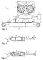
- Eine schematische Darstellung einer erfindungsgemässen Füllvorrichtung in einer Seitenansicht;
- Fig. 2
- eine schematische Darstellung eines Ausstosszylinders mit einem Kolben als Ausstosselement;
- Fig. 3
- eine schematische Darstellung eines Ausstosszylinders mit einer Schnecke als Ausstosselement;
- Fig. 4
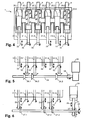
- eine schematische Darstellung der geöffneten Füllvorrichtung aus Fig. 1 von oben;
- Fig. 5
- eine schematische Darstellung des Antriebs der Schnecken zum Ausstossen der Füllung mittels einer Rotationsbewegung von oben;
- Fig. 6
- eine schematische Darstellung des Antriebs der Kolben zum Ausstossen der Füllung mittels einer Vorwärts- und Rückwärtsbewegung von oben;
- Fig. 7
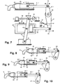
- eine schematische Darstellung des Antriebs aus Fig. 6 von der Seite,
- Fig. 8
- eine schematische Darstellung der Bewegung des Kolbens aus Fig. 6,
- Fig. 9
- eine schematische Darstellung der Verschiebung des vorderen und hinteren Umkehrpunktes sowie
- Fig. 10
- eine schematische Darstellung der Verschiebung nur des vorderen Umkehrpunktes.
- Fig. 1
- A schematic representation of a filling device according to the invention in a side view;
- Fig. 2
- a schematic representation of a discharge cylinder with a piston as Ausstosselement;
- Fig. 3
- a schematic representation of a discharge cylinder with a screw as Ausstosselement;
- Fig. 4
- a schematic representation of the opened filling device of Figure 1 from above.
- Fig. 5
- a schematic representation of the drive of the screw for ejecting the filling by means of a rotational movement from above;
- Fig. 6
- a schematic representation of the drive of the piston for ejecting the filling by means of a forward and backward movement from above;
- Fig. 7
- 1 is a schematic representation of the drive of FIG. 6 from the side,
- Fig. 8
- a schematic representation of the movement of the piston of Fig. 6,
- Fig. 9
- a schematic representation of the displacement of the front and rear reversal point and
- Fig. 10
- a schematic representation of the displacement of only the front reversal point.
Grundsätzlich sind in den Figuren gleiche Teile mit gleichen Bezugszeichen versehen.Basically, the same parts are provided with the same reference numerals in the figures.
In Figur 1 ist schematisch eine erfindungsgemässe Füllvorrichtung 1 zum Aufbringen einer Füllung auf einen Teig dargestellt. Die Füllvorrichtung 1 umfasst einen Trichter 2, in welchen die aufzubringende Füllung eingefüllt wird. Aufgrund der Schwerkraft oder mit Hilfe von zwei rotierenden Einzugswalzen 3 wird die Füllung im Trichter 2 nach unten befördert, wo sie durch eine Öffnung 4 aus dem Trichter 2 ausgestossen wird. Damit die Füllung effizienter zur Öffnung 4 befördert wird, sind die Einzugswalzen 3 mit exzentrisch mitrotierenden Lamellen 3.1 versehen. Die Rotationsrichtung der Einzugswalzen ist durch die Pfeile 3.2 und die Förderrichtung der Füllung durch die Pfeile 3.3 angedeutet. Anstelle von Lamellen 3.1 können die Einzugswalzen auch mit geeigneten Erhebungen wie z. B. Noppen oder Kämmen bzw. mit geeigneten Vertiefungen wie z. B. Löchern oder Nuten versehen werden.FIG. 1 schematically shows a
Direkt unterhalb des Trichters 2 ist ein Zylindergehäuse 5 positioniert, welches einen nicht sichtbaren, im Wesentlichen kreiszylinderförmigen Hohlraum aufweist, der nachfolgend als Ausstosszylinder bezeichnet wird. Die aus dem Trichter 2 ausgestossene Füllung wird durch eine im Zylindergehäuse 5 vorhandene Befüllungsöffnung 6, welche sich direkt unterhalb der Öffnung 4 des Trichters befindet, in den Ausstosszylinder befördert.Directly below the
Mit einem Ausstosselement 7, welches durch einen geeigneten Antrieb 8 angetrieben wird, wird die Füllung aus dem Ausstosszylinder ausgestossen und via einen Ausgang 9 in Richtung des Pfeiles 10 auf die Teigstücke 11 aufgebracht. Die Teigstücke 11 werden hierfür mittels einer Transportvorrichtung 12 unter dem Ausgang 9 der Füllvorrichtung 1 mit einer bestimmten Geschwindigkeit vorbeigeführt. In dem dargestellten Beispiel umfasst die Transportvorrichtung 12 zwei Rollen 13 sowie ein um die Rollen 13 herumgeführtes und um diese umlaufendes Förderband 14. Die Bewegungsrichtung des Förderbandes 14 ist durch die Pfeile 15 angedeutet. Der Antrieb der Transportvorrichtung 12 sowie die Zuführung der Teigstücke 11 auf das Förderband 14 wie auch die weitere Verarbeitung der gefüllten Teigstücke 11 ist nicht dargestellt.With an
Bei dem zu füllenden Teig kann es sich nicht nur wie dargestellt um einzelne Teigstücke 11, sondern auch um ein kontinuierliches Teigband handeln.The dough to be filled may be not only
Je nachdem, wie das Ausstosselement 7 ausgebildet ist und angetrieben wird, kann die Füllung wie dargestellt als Tupfen 16 oder auch als kontinuierlicher Füllungsstreifen auf dem Teig aufgebracht werden.Depending on how the
Zur Klarstellung ist anzumerken, dass in Figur 1 darstellungsbedingt zwar lediglich ein Ausgang 9 mit dem zugehörigen Ausstosszylinder sowie dem zugehörigen Ausstosselement 7 sichtbar ist, dass eine erfindungsgemässe Füllvorrichtung typischerweise jedoch mehrere Ausgänge 9 mit zugehörigem Ausstosszylinder und Ausstosselement 7 umfasst. Zum Ausstossen der Füllung kann nun in jedem Ausstosszylinder wahlweise entweder ein Kolben oder eine Schnecke verwendet werden, wobei ein Kolben jederzeit durch eine Schnecke bzw. eine Schnecke jederzeit durch einen Kolben ausgewechselt werden kann. Das Ausstossen der Füllung mit einem Kolben bzw. einer Schnecke ist in den Figuren 2 und 3 dargestellt.For clarification, it should be noted that although only one
Figur 2 zeigt ein Zylindergehäuse 5 mit einem Kolben 20 als Ausstosselement 7 im Ausstosszylinder 23. Der Kolben 20 wird im Ausstosszylinder 23 mittels eines Pleuels 21 in eine Vorwärts- und Rückwärtsbewegung versetzt, welche durch den Doppelpfeil 22 angedeutet ist. Der Pleuel 21 wird seinerseits durch den Antrieb 8 angetrieben, wobei zur Erzeugung der Vorwärts- und Rückwärtsbewegung gegebenenfalls ein entsprechendes, nicht dargestelltes Getriebe zwischengeschaltet werden kann.FIG. 2 shows a
Das Ausstossen der im Ausstosszylinder 23 vorhandenen Füllung erfolgt während der Vorwärtsbewegung des Kolbens 20 in Richtung des Ausgangs 9, wobei die Befüllungsöffnung 6 durch den Kolben 20 verschlossen wird. Dadurch kann der Kolben im vorderen Bereich des Ausstosszylinders 23 einen Druck auf die Füllung aufbauen und diese aus dem Ausstosszylinder ausstossen und durch den Ausgang 9 auf den Teig aufbringen. Während der Rückwärtsbewegung des Kolbens im Ausstosszylinder 23 wird der Ausstosszylinder 23 im Bereich des Ausgangs 9 verschlossen, wodurch sich ein Vakuum aufbaut. Wenn der Kolben 20 die Befüllungsöffnung 6 bei seiner Rückwärtsbewegung wieder freigibt, wird aufgrund des Vakuums im Ausstosszylinder 23 Füllung aus dem Trichter 2 angesogen. Dann kann das Ausstossen der Füllung erneut beginnen.The discharge of the filling present in the
Das Verschliessen des Ausstosszylinders 23 während der Rückwärtsbewegung des Kolbens 20 kann beispielsweise mit einer Klappe, einem Schlitzventil, einer Kugel oder einer beliebigen anderen Schliessvorrichtung erfolgen.The closing of the
Figur 3 zeigt ein Zylindergehäuse 5 mit einer Schnecke 30. Solche Schnecken werden auch als Förderschnecken oder Schneckenförderer bezeichnet. Die Schnecke 30 wird durch die Welle 31 in eine durch den Pfeil 32 angedeutete Rotationsbewegung versetzt. Die Welle 31 wird durch den Antrieb 8 angetrieben, wobei zur Erzeugung der Rotationsbewegung gegebenenfalls ein entsprechendes, nicht dargestelltes Getriebe zwischengeschaltet werden kann.FIG. 3 shows a
Das Ausstossen der im Ausstosszylinder 23 vorhandenen Füllung erfolgt hierbei durch die Schnecke, welche die Füllung während ihrer Rotation in Richtung des Ausgangs 8 befördert und so aus dem Ausstosszylinder 23 ausstösst.The ejection of the filling present in the
In Figur 4 ist schematisch eine erfindungsgemässe Füllvorrichtung mit sechs Ausgängen 9 sowie sechs zugehörigen Ausstosszylindern 23.1, 23.2, 23.3, 23.4, 23.5, 23.6 dargestellt. Die Ausstosszylinder 23.1, 23.4 und 23.5 sind beispielhaft mit einem Kolben 20.1, 20.2 und 20.3 und zugehörigen Pleueln 21.1, 21.2 und 21.3 bestückt. Die Ausstosszylinder 23.2, 23.3 und 23.6 sind beispielhaft mit einer Schnecke 30.1, 30.2 und 30.3 sowie zugehörigen Wellen 31.1, 31.2 und 31.3 bestückt.FIG. 4 schematically shows a filling device according to the invention with six
Wird einer oder werden mehrere der Ausgänge 9 nicht zum Aufbringen einer Füllung benötigt, können sie natürlich auch ausser Betrieb gesetzt werden. Dies geschieht beispielsweise, indem das eingesetzte Ausstosselement blockiert wird, damit es die Ausstossbewegung nicht ausführt. Es ist aber auch möglich, kein Ausstosselement in den jeweiligen Ausstosszylinder einzusetzen und die Befüllungsöffnung oder die Ausstossöffnung des Ausstosszylinders mit anderen, beliebigen Mitteln zu verschliessen. Prinzipiell könnte anstelle eines Ausstosszylinders auch eine andere Vorrichtung, beispielsweise ein modifizierter Ausstosszylinder, welcher überhaupt keine Befüllungsöffnung besitzt, eingesetzt werden.If one or more of the
Figur 5 zeigt, wie die Rotationsbewegung der Wellen 31.1, 31.2 und 31.3 und damit auch jene der Schnecken 30.1, 30.2 und 30.3 erzeugt wird. Ein Motor 33 versetzt eine Antriebswelle 34 in eine durch den Pfeil 35 angedeutete Rotationsbewegung. Diese wird durch jeweils ein Zahnradgetriebe 36.1, 36.2, 36.3, beispielsweise je zwei senkrecht zueinander stehende Kegelzahnräder, auf die Wellen 31.1, 31.2 und 31.3 übertragen.Figure 5 shows how the rotational movement of the shafts 31.1, 31.2 and 31.3 and thus also those of the screws 30.1, 30.2 and 30.3 is generated. A
Die Figuren 6 und 7 zeigen, wie die Vorwärts- und Rückwärtsbewegung der Pleuel 21.1, 21.2 und 21.3 und damit auch jene der Kolben 20.1, 20.2 und 20.3 erzeugt wird. Mit Hilfe eines Pneumatikzylinders 24 wird eine Kolbenstange 25 in eine Vorwärts- und Rückwärtsbewegung versetzt, welche durch die Doppelpfeile 26 angedeutet ist. Diese Vorwärts- und Rückwärtsbewegung wird über einen Hebel 27 auf eine Rotationsachse 28 übertragen, deren wechselnde Rotationsbewegung durch den Doppelpfeil 29 angedeutet ist. Mit je einem weiteren, an der Rotationsachse 28 befestigten Hebel 27.1, 27.2 und 27.3 wird die wechselnde Rotationsbewegung der Rotationsachse 28 schliesslich wieder in eine Vorwärts- und Rückwärtsbewegung der Pleuel 21.1, 21.2 und 21.3 umgewandelt.Figures 6 and 7 show how the forward and backward movement of the connecting rods 21.1, 21.2 and 21.3 and thus also those of the pistons 20.1, 20.2 and 20.3 is generated. With the aid of a
In Figur 7 sind weitere Aspekte dargestellt. So kann bei einem Kolbensystem beispielsweise die Füllmenge reguliert werden. Hierfür ist der gesamte Pneumatikzylinder 24 mit Hilfe eines Hebels 41, an welchem der Pneumatikzylinder 24 um eine Achse 43 drehbar aufgehängt ist, relativ zur Rotationsachse 28 hin- und her verschiebbar. Der Hebel 41 ist an seinem unteren Ende um eine relativ zur Rotationsachse 28 feste Achse 42 drehbar gelagert. An seinem oberen Ende ist der Hebel 41 via einen Bolzen 40 mit einer Spindel 44 derart verbunden, dass das obere Ende des Hebels 41 durch Drehen der Spindel 44 hin-und herbewegt werden kann. Durch die Verbindung des Pneumatikzylinders 24 mit dem Hebel 41 kann dieser folglich mittels Drehen der Spindel 44 relativ zur Rotationsachse 28 verschoben werden. Die Drehung der Spindel 44 und die Verschiebung des Hebels 41 bzw. des Pneumatikzylinders 24 ist durch die Doppelpfeile 45 angedeutet.FIG. 7 shows further aspects. For example, in a piston system, the capacity can be regulated. For this purpose, the entire
Bei der Rückwärtsbewegung des Kolbens 20.1 im Ausstosszylinder 23.1 wird die Befüllungsöffnung 6 (zumindest teilweise) freigegeben und die Füllung wird wie weiter oben beschrieben durch das entstehende Vakuum in den Ausstosszylinder 23.1 befördert. Hierbei ist zu beachten, dass der in Fig. 7 dargestellte Anschlag 50 sowie der Schalter 51 nicht in Betrieb sind. Dadurch kann der Kolben 20.1 im Ausstosszylinder 23.1 seine Rückwärtsbewegung vollständig ausführen.During the backward movement of the piston 20.1 in the ejection cylinder 23.1, the filling
Figur 8 zeigt die Grundstellung des Hebels 27.1, bei welcher sich der Kolben 20.1 im hinteren Umkehrpunkt 47 befindet und die Befüllungsöffnung 6 zum grössten Teil freigibt. Beim Ausstossen der Füllung bewegt sich der Kolben nach vorn in Richtung des Ausgangs 9. Die Füllmenge 49 wird nun bestimmt durch das Volumen, dass das vordere Ende des Kolbens 20.1 im Ausstosszylinder 23.1 ab dem vorderen Rand 6.1 der Befüllungsöffnung 6 bis zum vorderen Umkehrpunkt 46 überstreicht. Gestrichelt sind in Fig. 8 zudem die Positionen des Kolbens 20.1, des Pleuels 21.1 und des Hebels 27.1 eingezeichnet, wenn sich der Kolben 20.1 in seinem vorderen Umkehrpunkt 46 befindet. Da sich der Kolben 20.1 in seiner Grundstellung ziemlich weit rechts befindet, ist das überstrichene Volumen und damit die Füllmenge 49 klein.FIG. 8 shows the basic position of the
Ist nun, wie in Fig. 9 dargestellt, der Pneumatikzylinder 24 nach rechts verschoben, wandern der vordere Umkehrpunkt 46 und der hintere Umkehrpunkt 47 gemeinsam nach vorn in Richtung des Ausgangs 9. Dadurch wird das Volumen, das der Kolben ab dem vorderen Rand 6.1 der Befüllungsöffnung 6 bis zum vorderen Umkehrpunkt 46 überstreicht, und damit auch die Füllmenge 49, vergrössert. Hingegen bleibt dabei der Hub des Kolbens 20.1, also die Distanz zwischen den beiden Umkehrpunkten 46 und 47, im Wesentlichen konstant.Now, as shown in Fig. 9, the
Ein weiterer Aspekt, der in Figur 7 sowie in Figur 10 dargestellt ist, betrifft die Erhöhung der Anzahl Hübe pro Zeiteinheit. Am Hebel 27 ist ein Anschlag 50 und ein Schalter 51 ortsfest in Bezug auf den Ausstosszylinder 23.1, beispielsweise am Rahmen der Füllvorrichtung, befestigt. D.h. in der Darstellung in Fig. 10 sind im Gegensatz zur Darstellung in Fig. 8 der Anschlag 50 sowie der Schalter 51 in Betrieb. Wird nun der Schalter 51 während der Rückwärtsbewegung der Kolbenstange 25 und damit des Hebels 27 bzw. des Kolbens 20.1 im Ausstosszylinder 23.1 durch den Anschlag 50 betätigt, was durch den Doppelpfeil 48 angedeutet ist, wird der Pneumatikzylinder 24 umgehend derart angesteuert, dass sich die Kolbenstange 25 und damit auch der Kolben 20.1 wieder vorwärts bewegen. D. h. der Kolben 20.1 im Ausstosszylinder 23.1 kann seine Rückwärtsbewegung nicht vollständig ausführen, sondern wechselt unabhängig von der Position des vorderen Umkehrpunktes jeweils vorzeitig wieder zur Vorwärtsbewegung. Die Positionen des Anschlags 50 bzw. des Schalters 51 sind nun derart gewählt, dass bei der Rückwärtsbewegung des Kolbens 20.1 der Anschlag 50 den Schalter 51 auslöst, sobald der Kolben 20.1 den gewünschten hinteren Umkehrpunkt 47, der beispielsweise etwa in der Mitte der Befüllungsöffnung 6 liegt, erreicht hat.A further aspect, which is shown in FIG. 7 and in FIG. 10, concerns the increase in the number of strokes per unit of time. On the
Da hierbei wie bereits erwähnt die Rückwärtsbewegung des Kolbens 20.1 weniger weit ausgeführt wird, beginnt der Ausstosszyklus früher. Folglich ist die Anzahl der Hübe pro Zeiteinheit, d. h. die Ausstossfrequenz, mit welcher der Kolben die Füllung aus dem Ausstosszylinder 23.1 ausstösst, höher.Since, as already mentioned, the backward movement of the piston 20.1 is carried out less far, the ejection cycle starts earlier. Consequently, the number of strokes per unit time, i. H. the ejection frequency at which the piston discharges the filling from the ejection cylinder 23.1, higher.
Indem nun die Position des Pneumatikzylinders 24 mit Hilfe der Spindel 44 verändert wird, was durch den Doppelpfeil 45 angedeutet ist, kann die Position des vorderen Umkehrpunktes 46 eingestellt werden. Hierbei bleibt die Position des hinteren Umkehrpunktes 47 unverändert, denn diese wird allein durch die Anordnung des Schalters 51 und des Anschlags 50 bestimmt. Je weiter also der Pneumatikzylinder 24 gemäss der Darstellung in Figur 7 nach links verschoben wird, desto weiter rechts befindet sich der vordere Umkehrpunkt 46, desto geringer ist somit die Füllmenge 49 und desto kleiner wird gleichzeitig der Hub des Kolbens 20.1 und damit desto grösser die Ausstossfrequenz.By now the position of the
Selbstverständlich können die Positionen von Anschlag 50 und Schalter 51 auch vertauscht oder sowohl der Anschlag 50 als auch der Schalter 51 an anderen Orten positioniert werden. So könnte der Anschlag beispielsweise ortsfest in Bezug auf den Ausstosszylinder 23.1 oder an einem beliebigen anderen Ort wie beispielsweise am Pleuel 21.1, am Hebel 27.1 oder auch an der Achse 28 befestigt sein, wobei der Schalter derart positioniert werden muss, dass er vom Anschlag 50 im richtigen Moment betätigt werden kann. Natürlich ist es auch möglich, die Positionsbestimmung des Kolbens 20.1 mit beliebigen anderen Sensoren durchzuführen, damit die Rückwärtsbewegung des Kolbens 20.1 an einem bestimmten Punkt gestoppt und dessen Vorwärtsbewegung eingeleitet werden kann.Of course, the positions of
Zusammenfassend ist festzustellen, dass es die Erfindung erlaubt, in einer einzigen Füllvorrichtung die Füllung sowohl mittels Kolben als auch mittels Schnecken auf den Teig aufzubringen. Bei einem bestimmten Ausgang kann also je nach Wunsch zeitlich hintereinander mit einem Kolben oder einer Schnecke gefüllt werden. Und bei mehreren Ausgängen ist es daher erforderlichenfalls möglich, einen oder mehrere Ausgänge mit einem Kolben und gleichzeitig einen oder mehrere Ausgänge mit einer Schnecke zu betreiben.In summary, it should be noted that the invention allows the filling to be applied to the dough in a single filling device both by means of pistons and by means of screws. For a specific output, it is therefore possible to fill it in chronological succession with a piston or a screw, as desired. And with multiple outputs it is therefore possible, if necessary, to operate one or more outputs with one piston and at the same time one or more outputs with one screw.
Bei reinen Kolbensystemen ist zudem festzustellen, dass durch das vorzeitige Abbrechen der Rückwärtsbewegung der Kolben eine Erhöhung der Hubfrequenz erreicht werden kann. Dadurch ist es möglich, die gewünschten Backwaren schneller und somit günstiger herzustellen.In the case of pure piston systems, it should also be noted that an increase in the stroke frequency can be achieved by the premature termination of the backward movement of the pistons. This makes it possible to produce the desired baked goods faster and thus cheaper.
Claims (10)
- Device (1) with at least one outlet (9) for applying a stuffing to a dough-like food substance, in particular a dough, as well as a discharge cylinder (23.1-23.6) and a discharge element (20.1-20.3, 30.1-30.3) in each case for the at least one outlet, wherein the stuffing can be discharged from the discharge cylinder by the discharge element and applied to the food substance through the at least one outlet, characterised in that the discharge element of the at least one outlet comprises a piston (20.1-20.3) for discharging the stuffing through a forward and return movement (22) of the piston in the discharge cylinder or a worm (30.1-30.3) for discharging the stuffing through a rotational movement (32) of the worm, wherein a discharge element with a piston can be replaced by a discharge element with a worm and vice versa.
- Device according to Claim 1, characterised in that it comprises at least one drive (8) for producing a drive movement (35, 26) and at least one gear unit (36.1-36.3, 27, 27.1-27.3) in each case for each outlet for converting the drive movement into the forward and return movement of a piston or into the rotational movement of a worm.
- Device according to Claim 2, characterised in that it comprises a pneumatic drive (24) for producing the forward and return movement of a piston and a motor drive (33) for producing the rotational movement of a worm.
- Device according to any one of Claims 1 to 3, characterised in that an angular velocity of the rotational movement of a worm and/or a form of the worm can be varied.
- Device according to any one of Claims 1 to 4, characterised in that it is formed such that a piston (20.1) in the discharge cylinder (23.1) changes from the forward movement to the return movement at a front reversal point and from the return movement to the forward movement at a rear reversal point, wherein the discharge cylinder can be filled with the stuffing through a filling opening (6) during the return movement of the piston, and the stuffing can be discharged by the discharge cylinder during the forward movement of the piston, and that a frequency of the forward and return movement of the piston and/or a position of the front and at the same time of the rear reversal point relative to the filling opening can be varied.
- Device according to Claim 5, characterised in that a position of the rear reversal point and/or a position of the front reversal point can be set independently of the position of the respective other reversal point.
- Device according to any one of Claims 1 to 6, characterised in that a cross section of the discharge cylinder can be varied.
- Device according to any one of Claims 1 to 7, characterised in that it comprises a storage container (2) for the stuffing as well as a transport device (12) for transporting the food substance (11), wherein the stuffing can be conveyed out of the storage container, in particular by means of a feed device (3), into the discharge cylinder of the at least one outlet (9), and the food substance can be transported by the transport device past the at least one outlet, in particular below the at least one outlet.
- Device according to any one of Claims 1 to 8, characterised in that it comprises at least two and at most twenty outlets and a discharge cylinder and a discharge element in each case for each outlet.
- Device according to any one of Claims 1 to 9, characterised in that a discharge cylinder (23.1-23.6) is formed together with the corresponding discharge element (7) as a module such that the module, with the discharge element, can be replaced by a corresponding module with another discharge element.
Priority Applications (1)
| Application Number | Priority Date | Filing Date | Title |
|---|---|---|---|
| EP20030405863 EP1520477B1 (en) | 2003-10-02 | 2003-12-04 | Stuffing device for stuffed food products |
Applications Claiming Priority (3)
| Application Number | Priority Date | Filing Date | Title |
|---|---|---|---|
| EP03405711 | 2003-10-02 | ||
| EP03405711 | 2003-10-02 | ||
| EP20030405863 EP1520477B1 (en) | 2003-10-02 | 2003-12-04 | Stuffing device for stuffed food products |
Publications (2)
| Publication Number | Publication Date |
|---|---|
| EP1520477A1 EP1520477A1 (en) | 2005-04-06 |
| EP1520477B1 true EP1520477B1 (en) | 2007-01-03 |
Family
ID=37681359
Family Applications (1)
| Application Number | Title | Priority Date | Filing Date |
|---|---|---|---|
| EP20030405863 Expired - Lifetime EP1520477B1 (en) | 2003-10-02 | 2003-12-04 | Stuffing device for stuffed food products |
Country Status (3)
| Country | Link |
|---|---|
| EP (1) | EP1520477B1 (en) |
| DE (1) | DE50306201D1 (en) |
| ES (1) | ES2279086T3 (en) |
Family Cites Families (4)
| Publication number | Priority date | Publication date | Assignee | Title |
|---|---|---|---|---|
| JPS63164835A (en) * | 1986-12-26 | 1988-07-08 | レオン自動機株式会社 | Quantitative feeder |
| DE8715463U1 (en) * | 1987-11-21 | 1989-03-16 | Heinrich Doepke Maschinenfabrik, 2980 Norden, De | |
| US5517904A (en) * | 1994-02-14 | 1996-05-21 | The Pillsbury Company | Food product depositor |
| FR2814646B1 (en) * | 2000-10-03 | 2003-05-16 | Jacques Barde | METHOD AND DEVICE FOR TOPPING ONE OR MORE SANDWICHES |
-
2003
- 2003-12-04 EP EP20030405863 patent/EP1520477B1/en not_active Expired - Lifetime
- 2003-12-04 ES ES03405863T patent/ES2279086T3/en not_active Expired - Lifetime
- 2003-12-04 DE DE50306201T patent/DE50306201D1/en not_active Expired - Lifetime
Also Published As
| Publication number | Publication date |
|---|---|
| EP1520477A1 (en) | 2005-04-06 |
| DE50306201D1 (en) | 2007-02-15 |
| ES2279086T3 (en) | 2007-08-16 |
Similar Documents
| Publication | Publication Date | Title |
|---|---|---|
| DE2303436C2 (en) | Molding machine | |
| DE1604331C2 (en) | Device for dispensing and controlled depositing of precisely dosed amounts of a plasticized plastic | |
| DD241189A5 (en) | METHOD FOR INJECTING VISCOUS LIQUID IN BREAD OR CONFECTIONERY | |
| DD249847A5 (en) | DEVICE FOR QUANTITATIVE EXTRUDING OF FOODS | |
| AT391401B (en) | DEVICE FOR PORTIONING Dough | |
| DE19915259A1 (en) | Powder dispensing device comprises conveyor for e containers, feed chamber for powder and ceramic filler wheel | |
| DE102008055813B3 (en) | Device and method for dosing confectionery masses | |
| EP0403813B1 (en) | Method and apparatus for the dosed filling of liquid and pasty products, especially of foodstuffs or the like | |
| DE1812291B2 (en) | DEVICE FOR THE FORMATION OF TOBACCO PORTIONS OF LARGETY EQUAL WEIGHT | |
| EP1520477B1 (en) | Stuffing device for stuffed food products | |
| DE3630077C2 (en) | ||
| DE2556168C2 (en) | Baler for pressing old material | |
| DE2461892A1 (en) | Piston feeder for supply of dough - giving portions of consistant weight and volume | |
| DE60038688T2 (en) | SYSTEM FOR MACHINING PARTICULAR PRODUCTS | |
| DE3617413C2 (en) | ||
| DE3911246C2 (en) | ||
| DE3317608C1 (en) | Dry apportioner | |
| AT405007B (en) | LEAF CELL PUMP FOR PORTIONING A PASTE AND COMPRESSIBLE MASS AND METHOD FOR THEIR OPERATION | |
| DE3422521A1 (en) | DEVICE FOR VOLUMETRIC DELIVERY OF SCHUETTGUT | |
| DE2315977A1 (en) | Extruding machine for measured dough portions - with pressure exerted adjustable to suit texture of matl. | |
| DE1432969A1 (en) | Device for dividing dough or the like. | |
| DE3837674C1 (en) | ||
| DE1132464B (en) | Device for introducing sausage mass or similar material into tubular structures, e.g. B. in Daerme | |
| EP0594705B1 (en) | Device for shaping portions of dough | |
| DE803860C (en) | Dosing and filling device for butter molding and packaging machines |
Legal Events
| Date | Code | Title | Description |
|---|---|---|---|
| PUAI | Public reference made under article 153(3) epc to a published international application that has entered the european phase |
Free format text: ORIGINAL CODE: 0009012 |
|
| AK | Designated contracting states |
Kind code of ref document: A1 Designated state(s): AT BE BG CH CY CZ DE DK EE ES FI FR GB GR HU IE IT LI LU MC NL PT RO SE SI SK TR |
|
| AX | Request for extension of the european patent |
Extension state: AL LT LV MK |
|
| 17P | Request for examination filed |
Effective date: 20050811 |
|
| AKX | Designation fees paid |
Designated state(s): CH DE ES FI IT LI NL |
|
| GRAP | Despatch of communication of intention to grant a patent |
Free format text: ORIGINAL CODE: EPIDOSNIGR1 |
|
| GRAS | Grant fee paid |
Free format text: ORIGINAL CODE: EPIDOSNIGR3 |
|
| GRAA | (expected) grant |
Free format text: ORIGINAL CODE: 0009210 |
|
| AK | Designated contracting states |
Kind code of ref document: B1 Designated state(s): CH DE ES FI IT LI NL |
|
| REF | Corresponds to: |
Ref document number: 50306201 Country of ref document: DE Date of ref document: 20070215 Kind code of ref document: P |
|
| REG | Reference to a national code |
Ref country code: ES Ref legal event code: FG2A Ref document number: 2279086 Country of ref document: ES Kind code of ref document: T3 |
|
| PLBE | No opposition filed within time limit |
Free format text: ORIGINAL CODE: 0009261 |
|
| STAA | Information on the status of an ep patent application or granted ep patent |
Free format text: STATUS: NO OPPOSITION FILED WITHIN TIME LIMIT |
|
| 26N | No opposition filed |
Effective date: 20071005 |
|
| PG25 | Lapsed in a contracting state [announced via postgrant information from national office to epo] |
Ref country code: IT Free format text: LAPSE BECAUSE OF NON-PAYMENT OF DUE FEES Effective date: 20071204 |
|
| PGRI | Patent reinstated in contracting state [announced from national office to epo] |
Ref country code: IT Effective date: 20110616 |
|
| REG | Reference to a national code |
Ref country code: CH Ref legal event code: PCAR Free format text: NEW ADDRESS: EIGERSTRASSE 2 POSTFACH, 3000 BERN 14 (CH) |
|
| PGFP | Annual fee paid to national office [announced via postgrant information from national office to epo] |
Ref country code: FI Payment date: 20191220 Year of fee payment: 17 Ref country code: NL Payment date: 20191224 Year of fee payment: 17 |
|
| PGFP | Annual fee paid to national office [announced via postgrant information from national office to epo] |
Ref country code: CH Payment date: 20191218 Year of fee payment: 17 |
|
| PGFP | Annual fee paid to national office [announced via postgrant information from national office to epo] |
Ref country code: ES Payment date: 20200103 Year of fee payment: 17 Ref country code: IT Payment date: 20191220 Year of fee payment: 17 Ref country code: DE Payment date: 20200124 Year of fee payment: 17 |
|
| REG | Reference to a national code |
Ref country code: CH Ref legal event code: PFA Owner name: SEEWER AG, CH Free format text: FORMER OWNER: SEEWER AG, CH |
|
| REG | Reference to a national code |
Ref country code: DE Ref legal event code: R119 Ref document number: 50306201 Country of ref document: DE |
|
| REG | Reference to a national code |
Ref country code: FI Ref legal event code: MAE |
|
| PG25 | Lapsed in a contracting state [announced via postgrant information from national office to epo] |
Ref country code: FI Free format text: LAPSE BECAUSE OF NON-PAYMENT OF DUE FEES Effective date: 20201204 |
|
| REG | Reference to a national code |
Ref country code: CH Ref legal event code: PL |
|
| REG | Reference to a national code |
Ref country code: NL Ref legal event code: MM Effective date: 20210101 |
|
| PG25 | Lapsed in a contracting state [announced via postgrant information from national office to epo] |
Ref country code: NL Free format text: LAPSE BECAUSE OF NON-PAYMENT OF DUE FEES Effective date: 20210101 |
|
| PG25 | Lapsed in a contracting state [announced via postgrant information from national office to epo] |
Ref country code: IT Free format text: LAPSE BECAUSE OF NON-PAYMENT OF DUE FEES Effective date: 20201204 |
|
| PG25 | Lapsed in a contracting state [announced via postgrant information from national office to epo] |
Ref country code: LI Free format text: LAPSE BECAUSE OF NON-PAYMENT OF DUE FEES Effective date: 20201231 Ref country code: DE Free format text: LAPSE BECAUSE OF NON-PAYMENT OF DUE FEES Effective date: 20210701 Ref country code: CH Free format text: LAPSE BECAUSE OF NON-PAYMENT OF DUE FEES Effective date: 20201231 |
|
| REG | Reference to a national code |
Ref country code: ES Ref legal event code: FD2A Effective date: 20220207 |
|
| PG25 | Lapsed in a contracting state [announced via postgrant information from national office to epo] |
Ref country code: ES Free format text: LAPSE BECAUSE OF NON-PAYMENT OF DUE FEES Effective date: 20201205 |